EP2584677B1 - Drehwinkelgeber für einen Elektromotor, Elektromotor und Verfahren zum Herstellen eines solchen Drehwinkelgebers - Google Patents
Drehwinkelgeber für einen Elektromotor, Elektromotor und Verfahren zum Herstellen eines solchen Drehwinkelgebers Download PDFInfo
- Publication number
- EP2584677B1 EP2584677B1 EP12188691.5A EP12188691A EP2584677B1 EP 2584677 B1 EP2584677 B1 EP 2584677B1 EP 12188691 A EP12188691 A EP 12188691A EP 2584677 B1 EP2584677 B1 EP 2584677B1
- Authority
- EP
- European Patent Office
- Prior art keywords
- housing
- rotary encoder
- encoder
- circuit arrangement
- electric motor
- Prior art date
- Legal status (The legal status is an assumption and is not a legal conclusion. Google has not performed a legal analysis and makes no representation as to the accuracy of the status listed.)
- Not-in-force
Links
- 238000004519 manufacturing process Methods 0.000 title claims description 11
- 238000003780 insertion Methods 0.000 claims description 32
- 230000037431 insertion Effects 0.000 claims description 32
- 238000000034 method Methods 0.000 claims description 7
- 229920002994 synthetic fiber Polymers 0.000 claims 1
- 238000003466 welding Methods 0.000 description 3
- 238000011156 evaluation Methods 0.000 description 2
- 238000010438 heat treatment Methods 0.000 description 2
- 238000002347 injection Methods 0.000 description 2
- 239000007924 injection Substances 0.000 description 2
- 230000008646 thermal stress Effects 0.000 description 2
- 238000004804 winding Methods 0.000 description 2
- 230000004888 barrier function Effects 0.000 description 1
- 238000001746 injection moulding Methods 0.000 description 1
- 230000007257 malfunction Effects 0.000 description 1
- 238000013021 overheating Methods 0.000 description 1
- 238000000275 quality assurance Methods 0.000 description 1
Images
Classifications
-
- H—ELECTRICITY
- H02—GENERATION; CONVERSION OR DISTRIBUTION OF ELECTRIC POWER
- H02K—DYNAMO-ELECTRIC MACHINES
- H02K11/00—Structural association of dynamo-electric machines with electric components or with devices for shielding, monitoring or protection
- H02K11/20—Structural association of dynamo-electric machines with electric components or with devices for shielding, monitoring or protection for measuring, monitoring, testing, protecting or switching
- H02K11/21—Devices for sensing speed or position, or actuated thereby
Definitions
- the invention relates to a rotary encoder for an electric motor, wherein the rotary encoder has a donor element with a donor disc, which is adapted to be rotatably connected to a shaft of the electric motor and to be arranged concentrically with the shaft, and a fixed in a housing of the rotary encoder with a sensor arranged to detect a position of the encoder disc.
- the invention also relates to an electric motor with such a rotary encoder and a method for producing such a rotary encoder.
- Such a rotary encoder is known from the market.
- the circuit arrangement of the known rotary encoder is in the Housing of the rotary encoder eimate and welded to the housing.
- the housing When manufacturing this rotary encoder, the housing must be heated where it is to be welded to the circuitry. The heating takes a relatively long time, which leads to the fact that the welding of the circuit arrangement on the housing takes comparatively much time. The time required for the welding leads to relatively high production costs of the rotary encoder.
- the circuit arrangement is thermally stressed during welding.
- the thermal load of the circuit arrangement can lead to a failure rate of the circuit arrangement being increased or an operating time of the circuit arrangement being shortened.
- the increased failure rate or the shortened operating time can at best be difficult to recognize during the manufacture of the rotary encoder by quality assurance measures, because overheating of the circuit due to the thermal load often only after some operating time leads to a malfunction of the circuit.
- the object of the present invention is to provide a rotary encoder, which can be produced inexpensively and also has a lower failure rate and / or a longer service life.
- a rotary encoder according to claim 1 an electric motor according to claim 10 and a method for producing a rotary encoder according to claim 11 is proposed.
- a rotary encoder of the type mentioned is provided, which is characterized in that the housing has at least one locking element which engages the circuit arrangement and thereby fixed in the housing.
- the locking element allows a quick mounting of the circuit arrangement in the housing, without heating parts of the housing or the circuit arrangement have to. Therefore, the rotary encoder can be manufactured inexpensively without increasing the failure rate of the circuit due to thermal stress.
- the housing has at least one guide pin which extends along an insertion direction for insertion of the circuit arrangement into the housing and projects into a guide hole of the circuit arrangement fastened in the housing.
- the guide pin and the guide hole provide a guiding function such that the circuitry is properly positioned relative to the housing upon insertion into the housing and that it maintains its position within the housing, particularly in a direction orthogonal to the insertion direction.
- a simple insertion of the circuit arrangement into the housing with a relatively low insertion force is achieved if the latching element has an insertion bevel, which is inclined obliquely away from the contact surface with respect to an axis parallel to the insertion direction.
- the locking element has a retaining bevel, which is inclined relative to the axis parallel to the insertion direction to the contact surface obliquely, wherein the retaining bevel rests against the housing mounted in the circuit arrangement. Due to the retaining bevels, the circuit arrangement can then safely mounted in the housing are when dimensions of the circuit are subjected to manufacturing tolerances.
- a good hold of the circuit arrangement in the housing and a particularly simple assembly of the circuit arrangement are made possible if the latching element is elastically deformable at least in one area.
- the locking element is formed in a side wall of the housing, wherein the side wall adjacent to the housing bottom and with respect to this, preferably at right angles, is inclined.
- the latching element is arranged on the housing bottom and protrudes along the insertion direction of this.
- the housing together with the latching element and / or the guide pin is formed as a single component, preferably as an injection molded part made of plastic. In this way, the rotary encoder can be produced easily.
- an electric motor is provided with a rotary encoder, wherein the rotary encoder has a donor element with a donor disc which is rotatably connected to a shaft of the electric motor and arranged concentrically with the shaft, and a fixed in a housing of the rotary encoder circuit arrangement with a sensor adapted to detect a position of the encoder disk, and wherein the rotary encoder is a rotary encoder according to the invention described herein.
- a method of manufacturing a rotary encoder for a Electric motor wherein the rotary encoder has a donor element with a donor disc which is adapted to be rotatably connected to a shaft of the electric motor, and according to the method, a circuit arrangement with a sensor which is adapted to detect a position of the encoder disc in one Housing of the rotary encoder is mounted, and wherein the circuit arrangement is fixed in the housing such that at least one locking element engages the circuit arrangement and thereby fixed in the housing.
- circuit arrangement is inserted along an insertion direction into the housing until the latching element acts on the circuit arrangement in order to fix it in the housing.
- circuit arrangement is inserted into the housing until it rests against a contact surface of the housing, preferably a housing bottom.
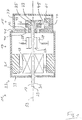
- FIG. 1 shows an electric motor 11 with a motor section 13 and a rotary encoder 15.
- the electric motor 11 shown here is a permanent magnet DC motor with a arranged on a shaft 17 rotor winding 19 and an inner side of a cylindrical housing portion 21 of a motor housing 23 of the electric motor
- the invention can also be used in conjunction with other types of electric motors.
- a collector 27 is arranged on the shaft 17, press against the contact surfaces, for example, as coals 28, formed brushes of the electric motor 11.
- the electric motor may also be brushless or otherwise formed.
- a drive section 31 of the shaft 17 is provided, which projects out of the motor housing 23 of the electric motor 11.
- the driving portion 31 may be connected to a driven part of a device in which the electric motor 11 is installed.
- a gear or the like may be arranged on the drive section 31.
- the drive section 31 can also be connected to a further shaft.
- the rotary encoder 15 is arranged at a second end 33 of the shaft 17 opposite the drive-side first end 29, the rotary encoder 15 is arranged.
- a portion of the shaft 17 at the second end 33 forms a donor portion 35 of the shaft 17, which protrudes from the motor housing 23 and in a Encoder housing 37 of the rotary encoder 15 protrudes.
- the drive section 31 projects out of the motor housing 23 from an opening in a second motor housing section 39.
- the encoder section 35 projects out of a first encoder opening 40 of the motor housing 23, which is located on a third motor housing section 41 of the motor housing 23.
- the first motor housing section 21 forms a cylinder jacket of the cylindrical housing 23, and the second motor housing section 39 and the third motor housing section 41 form opposite cover surfaces of the overall cylindrical housing 23.
- the shaft 17 also projects through a second encoder opening 42 of the encoder housing 37.
- the encoder housing is fastened to the motor housing 23 in such a way that the first encoder opening 40 and the second encoder opening 42 preferably lie next to one another congruently.
- the rotary encoder 15 has a transmitter element 43 with a preferably circular disk-shaped encoder disk 45, which is rotatably connected to the shaft 17. Furthermore, the rotary encoder 15 includes a sensor 47, which may be arranged to detect a position of the encoder disc 45.
- the encoder disk 45 has a hole pattern preferably arranged along a circular path concentric with the shaft 17, and the sensor 47 includes one or more fork light barriers arranged to detect individual holes of the hole pattern.
- the rotary encoder 15 may also have a donor disk, which is optically or magnetically or reflexively scanned or otherwise mechanically scanned.
- the rotary encoder 15 may be formed, for example, as an incremental encoder. With the help of a Evaluation device, the rotary encoder 15 for detecting an amount and / or the direction and / or the rotational speed of rotation of the shaft 17 may be provided.
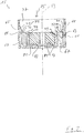
- FIG. 2 shows the encoder housing 37 and a circuit 61 of the rotary encoder 15 in detail.
- the shaft 17 and the encoder element 43 are not shown.
- a common longitudinal axis 53 of the encoder housing 37, the circuit 61, the shaft 17 and the transmitter element 43 are shown.
- the in FIG. 1 shown sensor 47 is part of the circuit 61.
- the circuit 61 may be an electronic circuit, which is arranged together with the sensor 47 in a circuit housing 63.
- the circuit arrangement 61 can have a plug connector with which the circuit arrangement 61 can be connected to an evaluation device for evaluating the rotary movements of the shaft 17 or the sensor element 43 detected by means of the circuit arrangement 61.
- the encoder housing 37 has latching elements 65 which act on the circuit arrangement 61, in particular on the circuit housing 63, in order to fix the circuit arrangement in the encoder housing 37.
- latching elements 65 act on the circuit arrangement 61, in particular on the circuit housing 63, in order to fix the circuit arrangement in the encoder housing 37.
- a pair of diametrically opposite to the longitudinal axis 53 opposite locking elements 65 is provided. Deviating from this, two or more such pairs of locking elements 65 may be provided. In addition, it is also conceivable to arrange an odd number of locking elements 65. For example, only one latching element 65 or three latching elements 65 can be provided.
- the encoder housing 37 is preferably designed as a plastic part produced by injection molding.
- the latching elements 65 are formed in a relative to a housing bottom 67 inclined side wall 69 of the encoder housing 37.
- the Side wall 69 may extend parallel to the longitudinal axis 53, and the housing bottom 67 may be arranged orthogonal to the longitudinal axis 53, so that the housing bottom 67 and the housing wall 69 are arranged at right angles to each other.
- At least one of the locking elements 65 has an insertion bevel 71 and a retaining bevel 73, which are arranged next to one another, so that an edge 74 is created between the insertion bevel 71 and the retaining bevel 73.
- the insertion bevel 71 and the retaining bevel 73 are inclined against each other.
- the insertion bevel is tilted obliquely away from the housing bottom 67 relative to an axis parallel to an insertion direction (arrow 75).
- the insertion direction 75 can, for example, run along the longitudinal axis 53, so that the axis parallel to the insertion direction can correspond to the longitudinal axis 53.
- the retaining bevel 73 is inclined obliquely to the housing bottom 67 relative to the axis parallel to the insertion direction 75, in particular with respect to the longitudinal axis 53.
- the retaining bevel 73 has a greater angle of inclination relative to the longitudinal axis 53 than the insertion bevel 71. That is, the insertion bevel 71 extends in the direction of insertion 75 flatter than the retaining bevel 73.
- each guide pin 77 extends within a guide hole 79 of the circuit 61 mounted in the encoder housing 37.
- the guide pins 77 may be integrally formed with the encoder housing 37.
- the number of guide pins 77 can be varied as desired. It can, for example, as in FIG. 2 shown, a pair of diametrically opposed guide pins 77 may be provided. There may be several such pairs of guide pins 77 be provided and / or there may be an odd number of guide pins 77.
- the housing bottom 67 has at least one contact surface 81 against which the circuit arrangement 61 bears against the housing bottom 67.
- the abutment surface 81 or the abutment surfaces 81 may or may be formed by elevations 83 on the housing bottom 67, which project into the interior of the encoder housing 37.
- the circuit 61 In order to install the circuit 61 in the encoder housing 37, the circuit 61 in the insertion direction 75 (in the illustration of FIG. 2 from above) inserted into the encoder housing 37.
- the locking elements 65 are elastically deformable.
- the circuit arrangement 61 passes through the insertion bevel 71, the insertion bevel 71 or the corresponding catch element 65 moves laterally, that is to say orthogonal to the longitudinal axis 53, to the outside, so that the circuit arrangement 61 can be moved past the latching elements 65.
- the circuit 61 is moved in the direction of insertion 75 until it rests against the contact surfaces 81.
- the latching elements 65 or the surfaces 71, 73 again move back at least slightly, so that the retaining bevel 73 of each latching element 65 bears against the circuit arrangement 61.
- the retaining bevel 73 causes the latching element 65 to abut the circuit arrangement 61 even if dimensions of the circuit arrangement 61, for example a height of the circuit arrangement or a width of the circuit arrangement 61, for example due to manufacturing tolerances, deviate from predetermined dimensions.
- the circuit arrangement 61 is clamped between the latching elements 65 and the contact surfaces 81.
- the guide pins 77 and the corresponding guide holes 79 ensure that a position of the circuit arrangement in the lateral direction, that is orthogonal to the longitudinal axis 53, is set sufficiently precisely.
- the guide pins 77 are not present. Therefore, in this embodiment, the circuit 61 need not have guide holes 79.
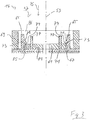
- FIG. 3 shows a further embodiment of the rotary encoder 15.
- the locking elements 65 are not formed in the side wall 69, but are arranged on the housing bottom 67 and protrude from the latter along the insertion direction 75 and / or along the longitudinal axis 53 from the housing bottom 67.
- the housing bottom 67 is configured as a base plate of the encoder housing 37, which may be arranged on the third motor housing portion 41.
- the side wall 69 is not formed integrally with the housing bottom but as part of a housing cover 86 of the encoder housing 37.
- the locking elements 65 have the same basic structure as in FIG. 2 shown latching elements 65 with the two slopes 71, 73.
- the latching elements 65 may form a single injection molded part with the housing bottom 67 and the guide pins 77.
- the insertion bevel 71 and the support slope 73 of the longitudinal axis 53 faces, so that the locking elements 65 cooperate with an at least substantially tangentially extending edge 85 of the circuit 61.
- the edge 85 may be bent and / or have a section with a straight course. Accordingly, the edge 74 extends between the two bevels 71, 73 at least approximately parallel to the edge 85 and / or at least approximately tangentially with respect to the longitudinal axis 53.
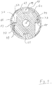
- the latching elements 65 cooperate with a further edge 87 of the circuit arrangement 61, which extends at least approximately along a radial direction with respect to the longitudinal axis 53.
- the edge 74 between the two bevels 71, 73 (FIG. Fig. 2, 3rd ) of the locking elements 65 extends at least approximately parallel to the further edge 87, that is, at least approximately in the radial direction with respect to the longitudinal axis 53 FIG. 4
- the guide pins 77 and the corresponding guide holes 79 may be provided. In an embodiment not shown, the guide pins 77 are not present. Accordingly, in this embodiment, the guide holes 79 can be omitted.
- the encoder housing 37 may have, for example, at its housing bottom 67 one or more mounting holes 89, with which the encoder housing 37 may be attached to the motor housing 23, for example by means of screws.
- the present invention provides the rotary encoder 15 and the electric motor 11, in which the circuit 61 can be fixed quickly and without thermal stress on the circuit 61 in the encoder housing 37.
- Fast mounting reduces manufacturing costs.
- the availability of the manufactured rotary encoder 15 or the electric motors 11 equipped therewith is increased.
Landscapes
- Engineering & Computer Science (AREA)
- Microelectronics & Electronic Packaging (AREA)
- Power Engineering (AREA)
- Transmission And Conversion Of Sensor Element Output (AREA)
Description
- Die Erfindung betrifft einen Drehwinkelgeber für einen Elektromotor, wobei der Drehwinkelgeber ein Geberelement mit einer Geberscheibe aufweist, die dazu eingerichtet ist, mit einer Welle des Elektromotors drehfest verbunden und konzentrisch mit der Welle angeordnet zu werden, und eine in einem Gehäuse des Drehwinkelgebers befestigte Schaltungsanordnung mit einem Sensor umfasst, der zum Erfassen einer Position der Geberscheibe eingerichtet ist. Die Erfindung betrifft außerdem einen Elektromotor mit einem solchen Drehwinkelgeber und ein Verfahren zum Herstellen eines solchen Drehwinkelgebers.
- Ein solcher Drehwinkelgeber ist vom Markt her bekannt. Die Schaltungsanordnung des bekannten Drehwinkelgebers ist in dem Gehäuse des Drehwinkelgebers eigesetzt und an dem Gehäuse festgeschweißt. Beim Herstellen dieses Drehwinkelgebers muss das Gehäuse an den Stellen, an den es mit der Schaltungsanordnung verschweißt werden soll, erhitzt werden. Das Erhitzen dauert relativ lange, was dazu führt, dass das Festschweißen der Schaltungsanordnung am Gehäuse vergleichsweise viel Zeit in Anspruch nimmt. Der Zeitaufwand für das Verschweißen führt zu relativ hohen Herstellkosten des Drehwinkelgebers.
- Darüber hinaus wird die Schaltungsanordnung beim Festschweißen thermisch belastet. Die thermische Belastung der Schaltungsanordnung kann dazu führen, dass eine Ausfallrate der Schaltungsanordnung erhöht oder eine Betriebsdauer der Schaltungsanordnung verkürzt wird. Die erhöhte Ausfallrate beziehungsweise die verkürzte Betriebsdauer kann während dem Herstellen des Drehwinkelgebers durch Qualitätssicherungsmaßnahmen allenfalls schwer erkannt werden, weil ein Überhitzen der Schaltungsanordnung infolge der thermischen Belastung oftmals erst nach einiger Betriebszeit zu einer Fehlfunktion der Schaltungsanordnung führt.
- Somit besteht die Aufgabe der vorliegenden Erfindung darin, einen Drehwinkelgeber zu schaffen, der kostengünstig hergestellt werden kann und zudem eine geringere Ausfallrate und/oder eine längere Betriebsdauer aufweist. Zu Lösung dieser Aufgabe wird ein Drehwinkelgeber nach Anspruch 1, ein Elektromotor nach Anspruch 10 und ein Verfahren zum Herstellen eines Drehwinkelgebers nach Anspruch 11 vorgeschlagen.
- In der
EP 0 836 079 A1 wird ein Drehwinkelgeber vorgeschlagen, der mittels eines Bajonettverschlusses stirnseitig am Motorgehäuse befestigt wird. - Gemäß einer Ausführungsform ist ein Drehwinkelgeber der eingangs genannten Art vorgesehen, der dadurch gekennzeichnet, ist, dass das Gehäuse mindestens ein Rastelement aufweist, das an der Schaltungsanordnung angreift und diese dadurch im Gehäuse fixiert. Das Rastelement erlaubt eine schnelle Montage der Schaltungsanordnung im Gehäuse, ohne dass Teile des Gehäuses oder der Schaltungsanordnung dabei erhitzt werden müssen. Deshalb kann der Drehwinkelgeber kostengünstig hergestellt werden, ohne die Ausfallrate der Schaltungsanordnung infolge einer thermischen Belastung zu erhöhen.
- Es ist besonders bevorzugt, dass das Gehäuse mindestens einen Führungsstift aufweist, der entlang einer Einschubrichtung zum Einschieben der Schaltungsanordnung in das Gehäuse verläuft und in ein Führungsloch der im Gehäuse befestigten Schaltungsanordnung hineinragt. Der Führungsstift und das Führungsloch bewirken eine Führungsfunktion derart, dass die Schaltungsanordnung beim Einsetzen in das Gehäuse richtig bezüglich des Gehäuses positioniert wird und dass sie ihre Position innerhalb des Gehäuses, insbesondere in einer Richtung orthogonal zur Einschubrichtung, beibehält.
- Um die Position der ins Gehäuse eingebauten Schaltungsanordnung in einer zur Einschubrichtung parallelen Längsrichtung festzulegen, kann vorgesehen sein, dass die in dem Gehäuse befestigte Schaltungsanordnung gehalten von dem Rastelement an einer Anlagefläche des Gehäuses, vorzugsweise eines Gehäusebodens, anliegt. Hierdurch wird auch eine gute Fixierung der Schaltungsanordnung erreicht, weil sie zwischen der Anlagefläche und dem Rastelement eingeklemmt ist.
- Ein einfaches Einschieben der Schaltungsanordnung ins Gehäuse mit einer relativ geringen Einschubkraft wird erreicht, wenn das Rastelement eine Einführschräge aufweist, die gegenüber einer zur Einschubrichtung parallelen Achse von der Anlagefläche schräg weggeneigt ist.
- Es ist bevorzugt, dass das Rastelement eine Halteschräge aufweist, die gegenüber der zur Einschubrichtung parallelen Achse zur Anlagefläche schräg hingeneigt ist, wobei die Halteschräge an der im Gehäuse befestigten Schaltungsanordnung anliegt. Aufgrund der Halteschräge kann die Schaltungsanordnung auch dann sicher im Gehäuse montiert werden, wenn Abmessungen der Schaltungsanordnung Fertigungstoleranzen unterworfen sind.
- Ein guter Halt der Schaltungsanordnung im Gehäuse und eine besonders einfache Montage der Schaltungsanordnung werden ermöglicht, wenn das Rastelement zumindest in einem Bereich elastisch verformbar ist.
- Um den Drehwinkelgeber bzw. dessen Rastelement einfach herstellen zu können, wird vorgeschlagen, dass das Rastelement in eine Seitenwand des Gehäuses eingeformt ist, wobei die Seitenwand an den Gehäuseboden angrenzt und gegenüber diesem, vorzugsweise rechtwinklig, geneigt ist.
- Alternativ hierzu kann vorgesehen sein, dass das Rastelement an dem Gehäuseboden angeordnet ist und entlang der Einschubrichtung von diesem abragt.
- Es ist bevorzugt, dass das Gehäuse mitsamt des Rastelements und/oder des Führungsstifts als ein einziges Bauteil, vorzugsweise als Spritzgussteil aus Kunststoff, gebildet ist. Auf diese Weise lässt sich der Drehwinkelgeber einfach herstellen.
- Gemäß einer weiteren Ausführungsform der Erfindung ist ein Elektromotor mit einem Drehwinkelgeber vorgesehen, wobei der Drehwinkelgeber ein Geberelement mit einer Geberscheibe aufweist, die mit einer Welle des Elektromotors drehfest verbunden und konzentrisch mit der Welle angeordnet ist, und eine in einem Gehäuse des Drehwinkelgebers befestigte Schaltungsanordnung mit einem Sensor umfasst, der zum Erfassen einer Position der Geberscheibe eingerichtet ist, und wobei es sich bei dem Drehwinkelgeber um einen hier beschriebenen Drehwinkelgeber gemäß der Erfindung handelt.
- Gemäß einer noch weiteren Ausführungsform der Erfindung ist ein Verfahren zum Herstellen eines Drehwinkelgebers für einen Elektromotor vorgesehen, wobei der Drehwinkelgeber ein Geberelement mit einer Geberscheibe aufweist, die dazu eingerichtet ist, mit einer Welle des Elektromotor drehfest verbunden zu werden, und gemäß dem Verfahren eine Schaltungsanordnung mit einem Sensor, der zum Erfassen einer Position der Geberscheibe eingerichtet ist, in einem Gehäuse des Drehwinkelgebers befestigt wird, und wobei die Schaltungsanordnung derart im Gehäuse befestigt wird, dass mindestens ein Rastelement an der Schaltungsanordnung angreift und diese dadurch im Gehäuse fixiert.
- Es ist bevorzugt, dass die Schaltungsanordnung entlang einer Einschubrichtung in das Gehäuse eingeschoben wird, bis das Rastelement an der Schaltungsanordnung angreift, um sie im Gehäuse zu fixieren.
- Weiter ist bevorzugt, dass die Schaltungsanordnung in das Gehäuse eingeschoben wird, bis sie an einer Anlagefläche des Gehäuses, vorzugsweise eines Gehäusebodens, anliegt.
- Um mittels des Verfahrens die Vorteile des hier beschriebenen Drehwinkelgebers zu erzielen, wird vorgeschlagen, einen Drehwinkelgeber gemäß der Erfindung herzustellen.
- Weitere Merkmale und Vorteile der Erfindung ergeben sich aus der nachfolgenden Beschreibung, in welcher exemplarische Ausführungsformen der Erfindung anhand der Zeichnungen näher erläutert werden. Dabei zeigen:
- Figur 1
- eine geschnittene Seitenansicht eines Elektromotors gemäß einer ersten Ausführungsform;
- Figur 2
- eine geschnittene Seitenansicht eines Drehwinkelgebers des Elektromotors aus
Fig. 1 ; - Figur 3
- eine geschnittene Seitenansicht eines Drehwinkelgebers gemäß einer zweiten Ausführungsform; und
- Figur 4
- eine geschnittene Draufsicht auf einen Drehwinkelgeber gemäß einer dritten Ausführungsform.
-
Figur 1 zeigt einen Elektromotor 11 mit einem Motorabschnitt 13 und einen Drehwinkelgeber 15. Bei dem hier gezeigten Elektromotor 11 handelt es sich um einen permanent erregten Gleichstrommotor mit einer an einer Welle 17 angeordneten Läuferwicklung 19 und einem an einer Innenseite eines zylindrischen Gehäuseabschnitts 21 eines Motorgehäuses 23 des Elektromotors 11 angeordneten schalenförmigen Arbeitsmagneten 25. Die Erfindung kann jedoch auch in Verbindung mit anderen Arten von Elektromotoren angewendet werden. - Zwischen der Läuferwicklung 19 und dem Drehwinkelgeber 15 ist an der Welle 17 ein Kollektor 27 angeordnet, gegen dessen Kontaktflächen beispielsweise als Kohlen 28, ausgebildete Bürsten des Elektromotors 11 drücken.
- Es versteht sich, dass der Elektromotor auch bürstenlos oder auf sonstige Weise ausgebildet sein kann.
- An einem in
Figur 1 links dargestellten ersten Ende 29 der Welle 17 ist ein Antriebsabschnitt 31 der Welle 17 vorgesehen, welcher aus dem Motorgehäuse 23 des Elektromotors 11 herausragt. Der Antriebsabschnitt 31 kann mit einem anzutreibenden Teil eines Geräts, in das der Elektromotor 11 eingebaut ist, verbunden werden. Beispielsweise kann am Antriebsabschnitt 31 ein Zahnrad oder dergleichen angeordnet sein. Der Antriebsabschnitt 31 kann auch mit einer weiteren Welle verbunden werden. - An einem dem antriebsseitigen ersten Ende 29 gegenüberliegenden zweiten Ende 33 der Welle 17 ist der Drehwinkelgeber 15 angeordnet. Ein Abschnitt der Welle 17 an dem zweiten Ende 33 bildet einen Geberabschnitt 35 der Welle 17, der aus dem Motorgehäuse 23 herausragt und in ein Gebergehäuse 37 des Drehwinkelgebers 15 hineinragt. In der gezeigten Ausführungsform mit dem insgesamt zylinderartig geformten Motorgehäuse 23 ragt der Antriebsabschnitt 31 aus einer Öffnung in einem zweiten Motorgehäuseabschnitt 39 aus dem Motorgehäuse 23 heraus. Der Geberabschnitt 35 ragt aus einer ersten Geberöffnung 40 des Motorgehäuses 23 heraus, welche sich an einem dritten Motorgehäuseabschnitt 41 des Motorgehäuses 23 befindet. In der gezeigten Ausführungsform bildet der erste Motorgehäuseabschnitt 21 einen Zylindermantel des zylinderförmigen Gehäuses 23, und der zweite Motorgehäuseabschnitt 39 sowie der dritte Motorgehäuseabschnitt 41 bilden einander gegenüberliegende Deckflächen des insgesamt zylinderförmigen Gehäuses 23.
- Die Welle 17 ragt auch durch eine zweite Geberöffnung 42 des Gebergehäuses 37. Das Gebergehäuse ist derart an dem Motorgehäuse 23 befestigt, dass die erste Geberöffnung 40 und die zweite Geberöffnung 42 vorzugsweise deckungsgleich nebeneinander liegen.
- Der Drehwinkelgeber 15 weist ein Geberelement 43 mit einer vorzugsweise kreisscheibenförmigen Geberscheibe 45 auf, die drehfest mit der Welle 17 verbunden ist. Ferner umfasst der Drehwinkelgeber 15 einen Sensor 47, der zum Erfassen einer Position der Geberscheibe 45 eingerichtet sein kann. In der gezeigten Ausführungsform weist die Geberscheibe 45 ein vorzugsweise entlang einer mit der Welle 17 konzentrischen Kreisbahn angeordnetes Lochmuster auf und der Sensor 47 umfasst eine oder mehrere Gabellichtschranken, die zum Erfassen einzelner Löcher des Lochmusters eingerichtet sind.
- Es versteht sich, dass der Drehwinkelgeber 15 auch eine Geberscheibe aufweisen kann, die optisch oder magnetisch oder reflexiv oder auf sonstige Weise mechanisch abgetastet wird.
- Der Drehwinkelgeber 15 kann beispielsweise als Inkrementalgeber ausgebildet sein. Mit Hilfe einer Auswerteeinrichtung kann der Drehwinkelgeber 15 zum Erfassen eines Betrags und/oder der Richtung und/oder der Drehzahl einer Drehung der Welle 17 vorgesehen sein.
-
Figur 2 zeigt das Gebergehäuse 37 und eine Schaltungsanordnung 61 des Drehwinkelgebers 15 im Detail. Der Übersichtlichkeit halber sind die Welle 17 und das Geberelement 43 nicht eingezeichnet. Jedoch sind eine gemeinsame Längsachse 53 des Gebergehäuses 37, der Schaltungsanordnung 61, der Welle 17 sowie des Geberelements 43 dargestellt. Der inFigur 1 dargestellte Sensor 47 ist Teil der Schaltungsanordnung 61. Bei der Schaltungsanordnung 61 kann es sich um eine elektronische Schaltung handeln, die mit samt dem Sensor 47 in einem Schaltungsgehäuse 63 angeordnet ist. Die Schaltungsanordnung 61 kann einen Steckverbinder aufweisen, mit dem die Schaltungsanordnung 61 an eine Auswerteeinrichtung zum Auswerten der mittels der Schaltungsanordnung 61 erfassten Drehbewegungen der Welle 17 beziehungsweise des Geberelements 43 angeschlossen werden kann. - Das Gebergehäuse 37 weist Rastelemente 65 auf, die an der Schaltungsanordnung 61, insbesondere an deren Schaltungsgehäuse 63, angreifen, um die Schaltungsanordnung im Gebergehäuse 37 zu fixieren. Bei dem in
Figur 2 gezeigten insgesamt zylinderförmigen Gebergehäuse 37 ist ein Paar diametral bezüglich der Längsachse 53 gegenüberliegender Rastelemente 65 vorgesehen. Abweichend hiervon können auch zwei oder mehrere solcher Paare von Rastelemente 65 vorgesehen sein. Darüber hinaus ist es auch denkbar, eine ungerade Anzahl von Rastelementen 65 anzuordnen. Es kann beispielsweise nur ein Rastelement 65 oder es können drei Rastelemente 65 vorgesehen werden. - Das Gebergehäuse 37 ist vorzugsweise als ein mittels Spritzgießen hergestelltes Kunststoffteil ausgeführt. Die Rastelemente 65 sind in eine gegenüber einem Gehäuseboden 67 geneigten Seitenwand 69 des Gebergehäuses 37 eingeformt. Die Seitenwand 69 kann parallel zu der Längsachse 53 verlaufen, und der Gehäuseboden 67 kann orthogonal zu der Längsachse 53 angeordnet sein, sodass der Gehäuseboden 67 und die Gehäusewand 69 rechtwinklig zueinander angeordnet sind.
- Zumindest eines der Rastelemente 65 weist eine Einführschräge 71 und eine Halteschräge 73 auf, die nebeneinander angeordnet sind, sodass zwischen der Einführschräge 71 und der Halteschräge 73 eine Kante 74 entsteht. Die Einführschräge 71 und die Halteschräge 73 sind gegeneinander geneigt. Insbesondere ist die Einführschräge gegenüber einer zu einer Einschubrichtung (Pfeil 75) parallelen Achse vom Gehäuseboden 67 schräg weggeneigt. Die Einschubrichtung 75 kann beispielsweise entlang der Längsachse 53 verlaufen, sodass die zur Einschubrichtung parallele Achse der Längsachse 53 entsprechen kann.
- Die Halteschräge 73 ist gegenüber der zur Einschubrichtung 75 parallelen Achse, insbesondere gegenüber der Längsachse 53, zum Gehäuseboden 67 schräg hingeneigt. Die Halteschräge 73 weist einen größeren Neigungswinkel gegenüber der Längsachse 53 auf als die Einführschräge 71. Das heißt, die Einführschräge 71 verläuft in Einschubrichtung 75 flacher als die Halteschräge 73.
- Vom Gehäuseboden 67 ragen Führungsstifte 77 ab, die innerhalb des Gebergehäuses 37 parallel zur Längsachse 53 und somit entlang der Einschubrichtung 75 verlaufen. Jeder Führungsstift 77 verläuft innerhalb eines Führungslochs 79 der im Gebergehäuse 37 befestigten Schaltungsanordnung 61.
- Wie in
Figur 2 dargestellt, können die Führungsstifte 77 einstückig mit dem Gebergehäuse 37 ausgebildet sein. Die Anzahl der Führungsstifte 77 kann beliebig variiert werden. Es kann beispielsweise, wie inFigur 2 gezeigt, ein Paar diametral gegenüberliegende Führungsstifte 77 vorgesehen sein. Es können mehrere solcher Paare von Führungsstiften 77 vorgesehen sein und/oder es kann eine ungerade Anzahl an Führungsstiften 77 vorhanden sein. - Der Gehäuseboden 67 weist mindestens eine Anlagefläche 81 auf, an der die Schaltungsanordnung 61 am Gehäuseboden 67 anliegt. Die Anlagefläche 81 oder die Anlageflächen 81 kann beziehungsweise können durch Erhebungen 83 am Gehäuseboden 67, die in das Innere des Gebergehäuses 37 hineinragen, gebildet sein.
- Um die Schaltungsanordnung 61 in das Gebergehäuse 37 einzubauen, wird die Schaltungsanordnung 61 in Einschubrichtung 75 (in der Darstellung von
Figur 2 von oben) in das Gebergehäuse 37 eingeschoben. Die Rastelemente 65 sind elastisch verformbar. Sobald die Schaltungsanordnung 61 die Einführschräge 71 passiert, bewegt sich die Einführschräge 71 beziehungsweise das entsprechende Rastelement 65 seitlich, das heißt orthogonal zur Längsachse 53, nach außen, sodass die Schaltungsanordnung 61 an den Rastelementen 65 vorbeibewegt werden kann. Die Schaltungsanordnung 61 wird solange in Einschubrichtung 75 bewegt, bis sie an den Anlageflächen 81 anliegt. Wenn die Schaltungsanordnung 61 an den Anlageflächen 81 anliegt, bewegen sich die Rastelemente 65 beziehungsweise die Flächen 71, 73 wieder zumindest etwas zurück, sodass die Halteschräge 73 jedes Rastelements 65 an der Schaltungsanordnung 61 anliegt. Die Haltesschräge 73 bewirkt, dass das Rastelement 65 auch dann an der Schaltungsanordnung 61 anliegt, wenn Abmessungen der Schaltungsanordnung 61, beispielsweise eine Höhe der Schaltungsanordnung oder eine Breite der Schaltungsanordnung 61, etwa aufgrund von Fertigungstoleranzen, von vorgegebenen Abmessungen abweichen. - Dadurch, dass die Halteschräge 73 der einzelnen Rastelemente 65 an der Schaltungsanordnung 61 anliegen, und die Rastelemente 65 elastisch verformbar sind, wird die Schaltungsanordnung 61 zwischen den Rastelementen 65 und den Anlageflächen 81 eingeklemmt. Die Führungsstifte 77 und die entsprechenden Führungslöcher 79 sorgen dafür, dass eine Lage der Schaltungsanordnung in seitlicher Richtung, das heißt orthogonal zur Längsachse 53, hinreichend genau festgelegt ist. In einer nicht gezeigten Ausführungsform der Erfindung sind die Führungsstifte 77 nicht vorhanden. Bei dieser Ausführungsform braucht die Schaltungsanordnung 61 deshalb keine Führungslöcher 79 aufzuweisen.
-
Figur 3 zeigt eine weitere Ausführungsform des Drehwinkelgebers 15. Anders als bei der inFigur 2 gezeigten Ausführungsform sind die Rastelemente 65 nicht in die Seitenwand 69 eingeformt, sondern sind am Gehäuseboden 67 angeordnet und ragen von diesem entlang der Einschubrichtung 75 und/oder entlang der Längsachse 53 vom Gehäuseboden 67 ab. Der Gehäuseboden 67 ist als eine Grundplatte des Gebergehäuses 37 ausgestaltet, die an dem dritten Motorgehäuseabschnitt 41 angeordnet sein kann. Anders als bei dem inFigur 2 gezeigten Gebergehäuse 37 ist die Seitenwand 69 nicht einstückig mit dem Gehäuseboden sondern als Teil eines Gehäusedeckels 86 des Gebergehäuses 37 ausgebildet. - Die Rastelemente 65 weisen denselben Grundaufbau wie die in
Figur 2 gezeigten Rastelemente 65 mit den beiden Schrägen 71, 73 auf. Die Rastelemente 65 können mit dem Gehäuseboden 67 und den Führungsstiften 77 ein einziges Spritzgussteil bilden. - In den Ausführungsformen, die in den
Figuren 2 und3 gezeigt sind, sind die Einführschräge 71 und die Halteschräge 73 der Längsachse 53 zugewandt, sodass die Rastelemente 65 mit einem zumindest im Wesentlichen tangential verlaufenden Rand 85 der Schaltungsanordnung 61 zusammenwirken. Je nach genauer Ausgestaltung der Schaltungsanordnung 61 kann der Rand 85 gebogen sein und/oder einen Abschnitt mit einem geraden Verlauf aufweisen. Dementsprechend verläuft die Kante 74 zwischen den beiden Schrägen 71, 73 zumindest annähernd parallel zu dem Rand 85 und/oder zumindest annähernd tangential bezüglich der Längsachse 53. - Bei der in
Figur 4 gezeigten Ausführungsform wirken die Rastelemente 65 mit einem weiteren Rand 87 der Schaltungsanordnung 61 zusammen, der zumindest annähernd entlang einer radialen Richtung bezüglich der Längsachse 53 verläuft. Die Kante 74 zwischen den beiden Schrägen 71, 73 (Fig. 2, 3 ) der Rastelemente 65 verläuft zumindest annähernd parallel zu dem weiteren Rand 87, das heißt zumindest annähernd in radialer Richtung bezüglich des Längsachse 53. Auch bei der inFigur 4 gezeigten Ausführungsform können die Führungsstifte 77 und die entsprechenden Führungslöcher 79 vorgesehen sein. In einer nicht gezeigten Ausführungsform sind die Führungsstifte 77 nicht vorhanden. Bei dieser Ausführungsform können dementsprechend auch die Führungslöcher 79 entfallen. - Das Gebergehäuse 37 kann beispielsweise an seinem Gehäuseboden 67 ein oder mehrere Befestigungslöcher 89 aufweisen, mit dem das Gebergehäuse 37 an dem Motorgehäuse 23 beispielsweise mittels Schrauben befestigt werden kann.
- Insgesamt stellt die vorliegende Erfindung den Drehwinkelgeber 15 beziehungsweise den Elektromotor 11 bereit, bei dem die Schaltungsanordnung 61 schnell und ohne thermische Belastung der Schaltungsanordnung 61 in dem Gebergehäuse 37 befestigt werden kann. Durch die schnelle Befestigung werden Fertigungskosten reduziert. Durch das Vermeiden der thermischen Belastung wird die Verfügbarkeit der hergestellten Drehwinkelgeber 15 beziehungsweise der damit ausgestatteten Elektromotoren 11 erhöht.
Claims (14)
- Drehwinkelgeber (15) für einen Elektromotor (11), wobei der Drehwinkelgeber (15) ein Geberelement (43) mit einer Geberscheibe (45) aufweist, die dazu eingerichtet ist, mit einer Welle (17) des Elektromotors (11) drehfest verbunden und konzentrisch mit der Welle (17) angeordnet zu werden, und eine in einem Gehäuse (37) des Drehwinkelgebers (15) befestigte Schaltungsanordnung (61) mit einem Sensor (47) umfasst, der zum Erfassen einer Position der Geberscheibe (45) eingerichtet ist, dadurch gekennzeichnet, dass das Gehäuse (37) mindestens ein Rastelement (65) aufweist, das an der Schaltungsanordnung (61) angreift und diese dadurch im Gehäuse (37) fixiert.
- Drehwinkelgeber (15) nach Anspruch 1, dadurch gekennzeichnet, dass das Gehäuse (23) mindestens einen Führungsstift (77) aufweist, der entlang einer Einschubrichtung (75) zum Einschieben der Schaltungsanordnung (61) in das Gehäuse (37) verläuft und in ein Führungsloch (79) der im Gehäuse (37) befestigten Schaltungsanordnung (61) hineinragt.
- Drehwinkelgeber (15) nach Anspruch 1 oder 2, dadurch gekennzeichnet, dass die in dem Gehäuse (37) befestigte Schaltungsanordnung (61) gehalten von dem Rastelement (65) an einer Anlagefläche (81) des Gehäuses, vorzugsweise eines Gehäusebodens (67), anliegt.
- Drehwinkelgeber (15) nach Anspruch 3, dadurch gekennzeichnet, dass das Rastelement (65) eine Einführschräge (71) aufweist, die gegenüber einer zur Einschubrichtung (75) parallelen Achse (53) von der Anlagefläche (81) weggeneigt ist.
- Drehwinkelgeber (15) nach Anspruch 3 oder 4, dadurch gekennzeichnet, dass das Rastelement (65) eine Halteschräge (73) aufweist, die gegenüber der zur Einschubrichtung (75) parallelen Achse (53) zur Anlagefläche (81) hingeneigt ist, wobei die Halteschräge (73) an der im Gehäuse (37) befestigten Schaltungsanordnung (61) anliegt.
- Drehwinkelgeber (15) nach einem der vorhergehenden Ansprüche, dadurch gekennzeichnet, dass das Rastelement (65) zumindest in einem Bereich elastisch verformbar ist.
- Drehwinkelgeber (15) nach einem der vorhergehenden Ansprüche, dadurch gekennzeichnet, dass das Rastelement (65) in eine Seitenwand (69) des Gehäuses (37) eingeformt ist, wobei die Seitenwand (69) an den Gehäuseboden (67) angrenzt und gegenüber diesem, vorzugsweise rechtwinklig, geneigt ist.
- Drehwinkelgeber (15) nach einem der Ansprüche 1 bis 6, dadurch gekennzeichnet, dass das Rastelement (65) an dem Gehäuseboden (67) angeordnet ist und entlang der Einschubrichtung (75) von diesem abragt.
- Drehwinkelgeber (15) nach einem der vorhergehenden Ansprüche, dadurch gekennzeichnet, dass das Gehäuse (37) mitsamt des Rastelements (65) und/oder des Führungsstifts (77) als ein einziges Bauteil, vorzugsweise als Spritzgussteil aus Kunststoff, gebildet ist.
- Elektromotor (11) mit einem Drehwinkelgeber (15), wobei der Drehwinkelgeber (15) ein Geberelement (43) mit einer Geberscheibe (45) aufweist, die mit einer Welle (17) des Elektromotors (11) drehfest verbunden und konzentrisch mit der Welle (17) angeordnet ist, und eine in einem Gehäuse (37) des Drehwinkelgebers (15) befestigte Schaltungsanordnung (61) mit einem Sensor (47) umfasst, der zum Erfassen einer Position der Geberscheibe (45) eingerichtet ist, dadurch gekennzeichnet, dass es sich bei dem Drehwinkelgeber (15) um einen Drehwinkelgeber (15) nach einem der vorhergehenden Ansprüche handelt.
- Verfahren zum Herstellen eines Drehwinkelgebers (15) für einen Elektromotor (11), wobei der Drehwinkelgeber (15) ein Geberelement (43) mit einer Geberscheibe (45) aufweist, die dazu eingerichtet ist, mit einer Welle (17) des Elektromotors (11) drehfest verbunden zu werden, und gemäß dem Verfahren eine Schaltungsanordnung (61) mit einem Sensor (47), der zum Erfassen einer Position der Geberscheibe (45) eingerichtet ist, in einem Gehäuse (37) des Drehwinkelgebers (15) befestigt wird, dadurch gekennzeichnet, dass die Schaltungsanordnung (61) derart im Gehäuse (37) befestigt wird, dass mindestens ein Rastelement (65) an der Schaltungsanordnung (61) angreift und diese dadurch im Gehäuse (37) fixiert.
- Verfahren nach Anspruch 11, dadurch gekennzeichnet, dass die Schaltungsanordnung (61) entlang einer Einschubrichtung (75) in das Gehäuse (37) eingeschoben wird, bis das Rastelement (65) an der Schaltungsanordnung (61) angreift, um sie im Gehäuse (37) zu fixieren.
- Verfahren nach Anspruch 11 oder 12, dadurch gekennzeichnet, dass die Schaltungsanordnung (61) in das Gehäuse (37) eingeschoben wird, bis sie an einer Anlagefläche (81) des Gehäuses (37), vorzugsweise eines Gehäusebodens (67), anliegt.
- Verfahren nach einem der Ansprüche 11 bis 13, dadurch gekennzeichnet, dass ein Drehwinkelgeber (15) nach einem der Ansprüche 1 bis 9 hergestellt wird.
Applications Claiming Priority (1)
| Application Number | Priority Date | Filing Date | Title |
|---|---|---|---|
| DE102011084629A DE102011084629A1 (de) | 2011-10-17 | 2011-10-17 | Drehwinkelgeber für einen Elektromotor, Elektromotor und Verfahren zum Herstellen eines solchen Drehwinkelgebers |
Publications (3)
| Publication Number | Publication Date |
|---|---|
| EP2584677A2 EP2584677A2 (de) | 2013-04-24 |
| EP2584677A3 EP2584677A3 (de) | 2015-11-11 |
| EP2584677B1 true EP2584677B1 (de) | 2017-01-04 |
Family
ID=47040584
Family Applications (1)
| Application Number | Title | Priority Date | Filing Date |
|---|---|---|---|
| EP12188691.5A Not-in-force EP2584677B1 (de) | 2011-10-17 | 2012-10-16 | Drehwinkelgeber für einen Elektromotor, Elektromotor und Verfahren zum Herstellen eines solchen Drehwinkelgebers |
Country Status (2)
| Country | Link |
|---|---|
| EP (1) | EP2584677B1 (de) |
| DE (1) | DE102011084629A1 (de) |
Cited By (1)
| Publication number | Priority date | Publication date | Assignee | Title |
|---|---|---|---|---|
| US20260051799A1 (en) * | 2024-08-19 | 2026-02-19 | Schaeffler Technologies AG & Co. KG | Electric motor with staked resolver stator |
Family Cites Families (4)
| Publication number | Priority date | Publication date | Assignee | Title |
|---|---|---|---|---|
| JPH06284641A (ja) * | 1993-03-30 | 1994-10-07 | Toshiba Lighting & Technol Corp | エンコーダ |
| DE19641929C2 (de) * | 1996-10-11 | 2000-01-05 | Ruhlatec Industrieprodukte | Encoder |
| US7109616B2 (en) * | 2003-10-16 | 2006-09-19 | Fasco Industries, Inc. | Electric motor with hall effect memory module |
| JP2007202382A (ja) * | 2005-12-28 | 2007-08-09 | Mabuchi Motor Co Ltd | 小型モータの光学式エンコーダ装置及びその製造方法 |
-
2011
- 2011-10-17 DE DE102011084629A patent/DE102011084629A1/de not_active Withdrawn
-
2012
- 2012-10-16 EP EP12188691.5A patent/EP2584677B1/de not_active Not-in-force
Non-Patent Citations (1)
| Title |
|---|
| None * |
Cited By (1)
| Publication number | Priority date | Publication date | Assignee | Title |
|---|---|---|---|---|
| US20260051799A1 (en) * | 2024-08-19 | 2026-02-19 | Schaeffler Technologies AG & Co. KG | Electric motor with staked resolver stator |
Also Published As
| Publication number | Publication date |
|---|---|
| EP2584677A2 (de) | 2013-04-24 |
| DE102011084629A1 (de) | 2013-04-18 |
| EP2584677A3 (de) | 2015-11-11 |
Similar Documents
| Publication | Publication Date | Title |
|---|---|---|
| DE112017005599B4 (de) | Lineare antriebsvorrichtung, motor, und lineare antriebsvorrichtung - herstellungsverfahren | |
| DE2706464C2 (de) | Elektrischer Schalter | |
| DE102012203946B4 (de) | Elektrische Maschine zum motorischen Verstellen beweglicher Teile im Kraftfahrzeug, sowie Verfahren zum Herstellen der elektrischen Maschine | |
| WO2015140096A1 (de) | Stabförmiger magnetfeldsensor | |
| EP2870053A1 (de) | Drehwinkelsensor | |
| EP2113989B1 (de) | Drehmomentstütze zur Befestigung des Gehäuses eines Drehgebers an einem Elektromotor | |
| WO2014187851A1 (de) | Kontaktvorrichtung zum herstellen eines elektrischen kontaktes zwischen einer leiterplatinen und einem elektromotor | |
| EP2615725A2 (de) | Antriebsvorrichtung, insbesondere für ein elektronisches Haushaltsgerät | |
| EP2693170A1 (de) | Statorkupplung | |
| DE19908522C2 (de) | Verbinderelement und Drehwinkelsensor, der von einem derartigen Verbinderelement Gebrauch macht | |
| EP2584677A2 (de) | Drehwinkelgeber für einen Elektromotor, Elektromotor und Verfahren zum Herstellen eines solchen Drehwinkelgebers | |
| WO2013053357A2 (de) | Stellantrieb | |
| WO2011113635A1 (de) | Kontaktstecker, antriebseinheit beinhaltend einen solchen, sowie herstellungsverfahren einer antriebseinheit | |
| DE102013210074A1 (de) | Antriebseinrichtung | |
| EP3167308B1 (de) | Ultraschallsensoreinrichtung für ein kraftfahrzeug, kraftfahrzeug und verfahren zur montage einer ultraschallsensoreinrichtung | |
| DE10159063B4 (de) | Vorrichtung zur lagerichtigen Befestigung einer Leiterplatte | |
| DE102012203735B4 (de) | Antrieb für ein Fenster oder dergleichen sowie ein Verfahren zur Montage des Antriebs | |
| DE10332302A1 (de) | Bürstenanordnung für eine elektrische Maschine | |
| DE1450768B1 (de) | Getriebe für geringe Leistungen | |
| EP1514706B1 (de) | Rastverbindung von Gehäuseteilen | |
| DE102005021050B3 (de) | Vorrichtung zum Sperren der Lenkspindel eines Kraftfahrzeugs | |
| AT517707B1 (de) | Antriebs- und Steuervorrichtung für ein Durchflussmessgerät | |
| EP1587175A1 (de) | Verbinder für signalübertragende Kabel | |
| DE102022117419A1 (de) | Drehwinkel-Sensor, Sensor-Baukasten sowie Verfahren zum Herstellen eines Drehwinkel-Sensors | |
| DE1450768C (de) | Getriebe fur geringe Leistungen |
Legal Events
| Date | Code | Title | Description |
|---|---|---|---|
| PUAI | Public reference made under article 153(3) epc to a published international application that has entered the european phase |
Free format text: ORIGINAL CODE: 0009012 |
|
| AK | Designated contracting states |
Kind code of ref document: A2 Designated state(s): AL AT BE BG CH CY CZ DE DK EE ES FI FR GB GR HR HU IE IS IT LI LT LU LV MC MK MT NL NO PL PT RO RS SE SI SK SM TR |
|
| AX | Request for extension of the european patent |
Extension state: BA ME |
|
| PUAL | Search report despatched |
Free format text: ORIGINAL CODE: 0009013 |
|
| AK | Designated contracting states |
Kind code of ref document: A3 Designated state(s): AL AT BE BG CH CY CZ DE DK EE ES FI FR GB GR HR HU IE IS IT LI LT LU LV MC MK MT NL NO PL PT RO RS SE SI SK SM TR |
|
| AX | Request for extension of the european patent |
Extension state: BA ME |
|
| RIC1 | Information provided on ipc code assigned before grant |
Ipc: H02K 11/00 20060101AFI20151008BHEP |
|
| 17P | Request for examination filed |
Effective date: 20151214 |
|
| RBV | Designated contracting states (corrected) |
Designated state(s): AL AT BE BG CH CY CZ DE DK EE ES FI FR GB GR HR HU IE IS IT LI LT LU LV MC MK MT NL NO PL PT RO RS SE SI SK SM TR |
|
| REG | Reference to a national code |
Ref country code: DE Ref legal event code: R079 Ref document number: 502012009197 Country of ref document: DE Free format text: PREVIOUS MAIN CLASS: H02K0011000000 Ipc: H02K0011210000 |
|
| RIC1 | Information provided on ipc code assigned before grant |
Ipc: H02K 11/21 20160101AFI20160428BHEP |
|
| GRAP | Despatch of communication of intention to grant a patent |
Free format text: ORIGINAL CODE: EPIDOSNIGR1 |
|
| INTG | Intention to grant announced |
Effective date: 20160627 |
|
| GRAS | Grant fee paid |
Free format text: ORIGINAL CODE: EPIDOSNIGR3 |
|
| GRAJ | Information related to disapproval of communication of intention to grant by the applicant or resumption of examination proceedings by the epo deleted |
Free format text: ORIGINAL CODE: EPIDOSDIGR1 |
|
| GRAL | Information related to payment of fee for publishing/printing deleted |
Free format text: ORIGINAL CODE: EPIDOSDIGR3 |
|
| INTC | Intention to grant announced (deleted) | ||
| GRAR | Information related to intention to grant a patent recorded |
Free format text: ORIGINAL CODE: EPIDOSNIGR71 |
|
| GRAA | (expected) grant |
Free format text: ORIGINAL CODE: 0009210 |
|
| AK | Designated contracting states |
Kind code of ref document: B1 Designated state(s): AL AT BE BG CH CY CZ DE DK EE ES FI FR GB GR HR HU IE IS IT LI LT LU LV MC MK MT NL NO PL PT RO RS SE SI SK SM TR |
|
| INTG | Intention to grant announced |
Effective date: 20161128 |
|
| REG | Reference to a national code |
Ref country code: GB Ref legal event code: FG4D Free format text: NOT ENGLISH |
|
| REG | Reference to a national code |
Ref country code: CH Ref legal event code: EP |
|
| REG | Reference to a national code |
Ref country code: AT Ref legal event code: REF Ref document number: 860122 Country of ref document: AT Kind code of ref document: T Effective date: 20170115 |
|
| REG | Reference to a national code |
Ref country code: IE Ref legal event code: FG4D Free format text: LANGUAGE OF EP DOCUMENT: GERMAN |
|
| REG | Reference to a national code |
Ref country code: CH Ref legal event code: NV Representative=s name: DREISS PATENTANWAELTE PARTG MBB, DE |
|
| REG | Reference to a national code |
Ref country code: DE Ref legal event code: R096 Ref document number: 502012009197 Country of ref document: DE |
|
| REG | Reference to a national code |
Ref country code: NL Ref legal event code: FP |
|
| REG | Reference to a national code |
Ref country code: LT Ref legal event code: MG4D |
|
| PG25 | Lapsed in a contracting state [announced via postgrant information from national office to epo] |
Ref country code: FI Free format text: LAPSE BECAUSE OF FAILURE TO SUBMIT A TRANSLATION OF THE DESCRIPTION OR TO PAY THE FEE WITHIN THE PRESCRIBED TIME-LIMIT Effective date: 20170104 Ref country code: IS Free format text: LAPSE BECAUSE OF FAILURE TO SUBMIT A TRANSLATION OF THE DESCRIPTION OR TO PAY THE FEE WITHIN THE PRESCRIBED TIME-LIMIT Effective date: 20170504 Ref country code: HR Free format text: LAPSE BECAUSE OF FAILURE TO SUBMIT A TRANSLATION OF THE DESCRIPTION OR TO PAY THE FEE WITHIN THE PRESCRIBED TIME-LIMIT Effective date: 20170104 Ref country code: GR Free format text: LAPSE BECAUSE OF FAILURE TO SUBMIT A TRANSLATION OF THE DESCRIPTION OR TO PAY THE FEE WITHIN THE PRESCRIBED TIME-LIMIT Effective date: 20170405 Ref country code: LT Free format text: LAPSE BECAUSE OF FAILURE TO SUBMIT A TRANSLATION OF THE DESCRIPTION OR TO PAY THE FEE WITHIN THE PRESCRIBED TIME-LIMIT Effective date: 20170104 Ref country code: NO Free format text: LAPSE BECAUSE OF FAILURE TO SUBMIT A TRANSLATION OF THE DESCRIPTION OR TO PAY THE FEE WITHIN THE PRESCRIBED TIME-LIMIT Effective date: 20170404 |
|
| PG25 | Lapsed in a contracting state [announced via postgrant information from national office to epo] |
Ref country code: SE Free format text: LAPSE BECAUSE OF FAILURE TO SUBMIT A TRANSLATION OF THE DESCRIPTION OR TO PAY THE FEE WITHIN THE PRESCRIBED TIME-LIMIT Effective date: 20170104 Ref country code: ES Free format text: LAPSE BECAUSE OF FAILURE TO SUBMIT A TRANSLATION OF THE DESCRIPTION OR TO PAY THE FEE WITHIN THE PRESCRIBED TIME-LIMIT Effective date: 20170104 Ref country code: RS Free format text: LAPSE BECAUSE OF FAILURE TO SUBMIT A TRANSLATION OF THE DESCRIPTION OR TO PAY THE FEE WITHIN THE PRESCRIBED TIME-LIMIT Effective date: 20170104 Ref country code: BG Free format text: LAPSE BECAUSE OF FAILURE TO SUBMIT A TRANSLATION OF THE DESCRIPTION OR TO PAY THE FEE WITHIN THE PRESCRIBED TIME-LIMIT Effective date: 20170404 Ref country code: PT Free format text: LAPSE BECAUSE OF FAILURE TO SUBMIT A TRANSLATION OF THE DESCRIPTION OR TO PAY THE FEE WITHIN THE PRESCRIBED TIME-LIMIT Effective date: 20170504 Ref country code: PL Free format text: LAPSE BECAUSE OF FAILURE TO SUBMIT A TRANSLATION OF THE DESCRIPTION OR TO PAY THE FEE WITHIN THE PRESCRIBED TIME-LIMIT Effective date: 20170104 Ref country code: LV Free format text: LAPSE BECAUSE OF FAILURE TO SUBMIT A TRANSLATION OF THE DESCRIPTION OR TO PAY THE FEE WITHIN THE PRESCRIBED TIME-LIMIT Effective date: 20170104 |
|
| REG | Reference to a national code |
Ref country code: DE Ref legal event code: R097 Ref document number: 502012009197 Country of ref document: DE |
|
| REG | Reference to a national code |
Ref country code: FR Ref legal event code: PLFP Year of fee payment: 6 |
|
| PG25 | Lapsed in a contracting state [announced via postgrant information from national office to epo] |
Ref country code: RO Free format text: LAPSE BECAUSE OF FAILURE TO SUBMIT A TRANSLATION OF THE DESCRIPTION OR TO PAY THE FEE WITHIN THE PRESCRIBED TIME-LIMIT Effective date: 20170104 Ref country code: EE Free format text: LAPSE BECAUSE OF FAILURE TO SUBMIT A TRANSLATION OF THE DESCRIPTION OR TO PAY THE FEE WITHIN THE PRESCRIBED TIME-LIMIT Effective date: 20170104 Ref country code: SK Free format text: LAPSE BECAUSE OF FAILURE TO SUBMIT A TRANSLATION OF THE DESCRIPTION OR TO PAY THE FEE WITHIN THE PRESCRIBED TIME-LIMIT Effective date: 20170104 Ref country code: CZ Free format text: LAPSE BECAUSE OF FAILURE TO SUBMIT A TRANSLATION OF THE DESCRIPTION OR TO PAY THE FEE WITHIN THE PRESCRIBED TIME-LIMIT Effective date: 20170104 |
|
| PLBE | No opposition filed within time limit |
Free format text: ORIGINAL CODE: 0009261 |
|
| STAA | Information on the status of an ep patent application or granted ep patent |
Free format text: STATUS: NO OPPOSITION FILED WITHIN TIME LIMIT |
|
| PG25 | Lapsed in a contracting state [announced via postgrant information from national office to epo] |
Ref country code: DK Free format text: LAPSE BECAUSE OF FAILURE TO SUBMIT A TRANSLATION OF THE DESCRIPTION OR TO PAY THE FEE WITHIN THE PRESCRIBED TIME-LIMIT Effective date: 20170104 Ref country code: SM Free format text: LAPSE BECAUSE OF FAILURE TO SUBMIT A TRANSLATION OF THE DESCRIPTION OR TO PAY THE FEE WITHIN THE PRESCRIBED TIME-LIMIT Effective date: 20170104 |
|
| 26N | No opposition filed |
Effective date: 20171005 |
|
| PG25 | Lapsed in a contracting state [announced via postgrant information from national office to epo] |
Ref country code: SI Free format text: LAPSE BECAUSE OF FAILURE TO SUBMIT A TRANSLATION OF THE DESCRIPTION OR TO PAY THE FEE WITHIN THE PRESCRIBED TIME-LIMIT Effective date: 20170104 |
|
| PG25 | Lapsed in a contracting state [announced via postgrant information from national office to epo] |
Ref country code: MC Free format text: LAPSE BECAUSE OF FAILURE TO SUBMIT A TRANSLATION OF THE DESCRIPTION OR TO PAY THE FEE WITHIN THE PRESCRIBED TIME-LIMIT Effective date: 20170104 |
|
| REG | Reference to a national code |
Ref country code: IE Ref legal event code: MM4A |
|
| PG25 | Lapsed in a contracting state [announced via postgrant information from national office to epo] |
Ref country code: LU Free format text: LAPSE BECAUSE OF NON-PAYMENT OF DUE FEES Effective date: 20171016 |
|
| REG | Reference to a national code |
Ref country code: BE Ref legal event code: MM Effective date: 20171031 |
|
| PG25 | Lapsed in a contracting state [announced via postgrant information from national office to epo] |
Ref country code: BE Free format text: LAPSE BECAUSE OF NON-PAYMENT OF DUE FEES Effective date: 20171031 |
|
| PG25 | Lapsed in a contracting state [announced via postgrant information from national office to epo] |
Ref country code: MT Free format text: LAPSE BECAUSE OF FAILURE TO SUBMIT A TRANSLATION OF THE DESCRIPTION OR TO PAY THE FEE WITHIN THE PRESCRIBED TIME-LIMIT Effective date: 20170104 |
|
| REG | Reference to a national code |
Ref country code: FR Ref legal event code: PLFP Year of fee payment: 7 |
|
| PG25 | Lapsed in a contracting state [announced via postgrant information from national office to epo] |
Ref country code: IE Free format text: LAPSE BECAUSE OF NON-PAYMENT OF DUE FEES Effective date: 20171016 |
|
| PGFP | Annual fee paid to national office [announced via postgrant information from national office to epo] |
Ref country code: NL Payment date: 20181022 Year of fee payment: 7 |
|
| PGFP | Annual fee paid to national office [announced via postgrant information from national office to epo] |
Ref country code: GB Payment date: 20181018 Year of fee payment: 7 |
|
| PG25 | Lapsed in a contracting state [announced via postgrant information from national office to epo] |
Ref country code: HU Free format text: LAPSE BECAUSE OF FAILURE TO SUBMIT A TRANSLATION OF THE DESCRIPTION OR TO PAY THE FEE WITHIN THE PRESCRIBED TIME-LIMIT; INVALID AB INITIO Effective date: 20121016 |
|
| PG25 | Lapsed in a contracting state [announced via postgrant information from national office to epo] |
Ref country code: CY Free format text: LAPSE BECAUSE OF NON-PAYMENT OF DUE FEES Effective date: 20170104 |
|
| PG25 | Lapsed in a contracting state [announced via postgrant information from national office to epo] |
Ref country code: MK Free format text: LAPSE BECAUSE OF FAILURE TO SUBMIT A TRANSLATION OF THE DESCRIPTION OR TO PAY THE FEE WITHIN THE PRESCRIBED TIME-LIMIT Effective date: 20170104 |
|
| PG25 | Lapsed in a contracting state [announced via postgrant information from national office to epo] |
Ref country code: TR Free format text: LAPSE BECAUSE OF FAILURE TO SUBMIT A TRANSLATION OF THE DESCRIPTION OR TO PAY THE FEE WITHIN THE PRESCRIBED TIME-LIMIT Effective date: 20170104 |
|
| REG | Reference to a national code |
Ref country code: NL Ref legal event code: MM Effective date: 20191101 |
|
| PG25 | Lapsed in a contracting state [announced via postgrant information from national office to epo] |
Ref country code: AL Free format text: LAPSE BECAUSE OF FAILURE TO SUBMIT A TRANSLATION OF THE DESCRIPTION OR TO PAY THE FEE WITHIN THE PRESCRIBED TIME-LIMIT Effective date: 20170104 |
|
| PG25 | Lapsed in a contracting state [announced via postgrant information from national office to epo] |
Ref country code: NL Free format text: LAPSE BECAUSE OF NON-PAYMENT OF DUE FEES Effective date: 20191101 |
|
| GBPC | Gb: european patent ceased through non-payment of renewal fee |
Effective date: 20191016 |
|
| PG25 | Lapsed in a contracting state [announced via postgrant information from national office to epo] |
Ref country code: GB Free format text: LAPSE BECAUSE OF NON-PAYMENT OF DUE FEES Effective date: 20191016 |
|
| PGFP | Annual fee paid to national office [announced via postgrant information from national office to epo] |
Ref country code: AT Payment date: 20211019 Year of fee payment: 10 Ref country code: DE Payment date: 20211208 Year of fee payment: 10 |
|
| PGFP | Annual fee paid to national office [announced via postgrant information from national office to epo] |
Ref country code: IT Payment date: 20211029 Year of fee payment: 10 Ref country code: FR Payment date: 20211021 Year of fee payment: 10 Ref country code: CH Payment date: 20211022 Year of fee payment: 10 |
|
| REG | Reference to a national code |
Ref country code: DE Ref legal event code: R119 Ref document number: 502012009197 Country of ref document: DE |
|
| REG | Reference to a national code |
Ref country code: CH Ref legal event code: PL |
|
| REG | Reference to a national code |
Ref country code: AT Ref legal event code: MM01 Ref document number: 860122 Country of ref document: AT Kind code of ref document: T Effective date: 20221016 |
|
| PG25 | Lapsed in a contracting state [announced via postgrant information from national office to epo] |
Ref country code: LI Free format text: LAPSE BECAUSE OF NON-PAYMENT OF DUE FEES Effective date: 20221031 Ref country code: FR Free format text: LAPSE BECAUSE OF NON-PAYMENT OF DUE FEES Effective date: 20221031 Ref country code: DE Free format text: LAPSE BECAUSE OF NON-PAYMENT OF DUE FEES Effective date: 20230503 Ref country code: CH Free format text: LAPSE BECAUSE OF NON-PAYMENT OF DUE FEES Effective date: 20221031 Ref country code: AT Free format text: LAPSE BECAUSE OF NON-PAYMENT OF DUE FEES Effective date: 20221016 |
|
| PG25 | Lapsed in a contracting state [announced via postgrant information from national office to epo] |
Ref country code: IT Free format text: LAPSE BECAUSE OF NON-PAYMENT OF DUE FEES Effective date: 20221016 |