EP2584237B1 - Dispositif de fixation d'une unité de tuyau - Google Patents
Dispositif de fixation d'une unité de tuyau Download PDFInfo
- Publication number
- EP2584237B1 EP2584237B1 EP20120186991 EP12186991A EP2584237B1 EP 2584237 B1 EP2584237 B1 EP 2584237B1 EP 20120186991 EP20120186991 EP 20120186991 EP 12186991 A EP12186991 A EP 12186991A EP 2584237 B1 EP2584237 B1 EP 2584237B1
- Authority
- EP
- European Patent Office
- Prior art keywords
- cuff
- pipe unit
- clamping
- section
- connection
- Prior art date
- Legal status (The legal status is an assumption and is not a legal conclusion. Google has not performed a legal analysis and makes no representation as to the accuracy of the status listed.)
- Not-in-force
Links
Images


Classifications
-
- F—MECHANICAL ENGINEERING; LIGHTING; HEATING; WEAPONS; BLASTING
- F16—ENGINEERING ELEMENTS AND UNITS; GENERAL MEASURES FOR PRODUCING AND MAINTAINING EFFECTIVE FUNCTIONING OF MACHINES OR INSTALLATIONS; THERMAL INSULATION IN GENERAL
- F16L—PIPES; JOINTS OR FITTINGS FOR PIPES; SUPPORTS FOR PIPES, CABLES OR PROTECTIVE TUBING; MEANS FOR THERMAL INSULATION IN GENERAL
- F16L7/00—Supporting of pipes or cables inside other pipes or sleeves, e.g. for enabling pipes or cables to be inserted or withdrawn from under roads or railways without interruption of traffic
-
- F—MECHANICAL ENGINEERING; LIGHTING; HEATING; WEAPONS; BLASTING
- F23—COMBUSTION APPARATUS; COMBUSTION PROCESSES
- F23J—REMOVAL OR TREATMENT OF COMBUSTION PRODUCTS OR COMBUSTION RESIDUES; FLUES
- F23J13/00—Fittings for chimneys or flues
- F23J13/04—Joints; Connections
-
- F—MECHANICAL ENGINEERING; LIGHTING; HEATING; WEAPONS; BLASTING
- F23—COMBUSTION APPARATUS; COMBUSTION PROCESSES
- F23J—REMOVAL OR TREATMENT OF COMBUSTION PRODUCTS OR COMBUSTION RESIDUES; FLUES
- F23J2213/00—Chimneys or flues
- F23J2213/10—Linings
- F23J2213/101—Fastening means therefor
-
- F—MECHANICAL ENGINEERING; LIGHTING; HEATING; WEAPONS; BLASTING
- F23—COMBUSTION APPARATUS; COMBUSTION PROCESSES
- F23J—REMOVAL OR TREATMENT OF COMBUSTION PRODUCTS OR COMBUSTION RESIDUES; FLUES
- F23J2213/00—Chimneys or flues
- F23J2213/20—Joints; Connections
- F23J2213/202—Joints; Connections between duct or stack sections
-
- F—MECHANICAL ENGINEERING; LIGHTING; HEATING; WEAPONS; BLASTING
- F23—COMBUSTION APPARATUS; COMBUSTION PROCESSES
- F23J—REMOVAL OR TREATMENT OF COMBUSTION PRODUCTS OR COMBUSTION RESIDUES; FLUES
- F23J2900/00—Special arrangements for conducting or purifying combustion fumes; Treatment of fumes or ashes
- F23J2900/13021—Means for supporting the lining of conducting means, e.g. ducts or chimneys
Definitions
- the invention relates to a device for fixing a pipe unit, in particular in a heating system in a residential building, according to the preamble of claim 1.
- Such a device is known from DE 200 03 980 U1 known.
- the known device has a sleeve-like element, at the two end portions of which a part of a clamping device is fastened or arranged.
- the tensioning device is designed in the form of a clamping buckle connection which has a hook-shaped part which is arranged at the one end of the sleeve-like element and which cooperates with a wire bow which can be tensioned with a clamping lever.
- the known clamping device can be produced by moving the clamping lever, the required clamping force.
- the known tensioning device works satisfactorily only when the tubes connected to the tensioning device are within a predetermined diameter range.
- the required clamping force can not be generated by means of the known clamping device designed as a clamping device, whereas if the tube diameters are too large, the required actuating force is relatively high or this force can lead to damage or deformation of the clamping device.
- EP 0 837 282 A2 and the DE 102 05 989 C1 each show devices for fixing a pipe unit according to the preamble of claim 1, each having a tool-operated clamping device in the form of a clamping buckle connection.
- the problem of problem-free handling described above with regard to the applied clamping forces and the required actuating forces is also given in these clamping buckle connections.
- the accessibility to particular the end portions of the sleeve-like element is often difficult, especially if the assembly of the device must be carried out within the shaft. This makes it difficult for a fitter or operator, the two To grip end portions of the sleeve-like element or bring them together in the desired manner (in a training with a latching connection) and to introduce the force required to form the latching connection in the end regions.
- the inventor has set itself the object to develop a device for fixing a pipe unit according to the preamble of claim 1 such that a particularly simple handling of the device is made possible on the pipe unit.
- a particularly simple handling while a particularly simple forming a locking position of the device on the tube unit or a particularly simple redissolution of the device of the tube unit, even under spatially difficult conditions, understood, at the same time with the lowest possible operating force high clamping force can be achieved should, which moves the two end portions of the sleeve-like element against or over each other, so that a secure grip on the tube unit is made possible.
- the actuating element thus serves, for example, to allow a contraction of the two end regions when the actuating element is pivoted. It can be achieved by a corresponding size or geometry of the actuating element, a power gain.
- the actuating element has a cooperating with the first gear geometry portion which cooperates with the first gear geometry in the manner of a ratchet, so that upon movement of the actuating element in one direction, the circumference of the element decreases and upon movement of the actuator in the other, opposite direction, the element maintains its circumference.
- a continuous clamping or a continuous reduction in the circumference of the sleeve-like element is effected, wherein, in particular during the pivoting back of the actuating element, a release of the device from the tube device is reliably avoided.
- actuating element In a first structural embodiment of the actuating element, it is provided that this is designed in the form of a back and forth pivoting actuating plate. Such a design has the advantage that it can be easily recognized by an operator and can be intuitively detected in terms of its function and thus can be operated particularly easily.
- an actuator plate can be particularly well tangible or tangible, for example, by a corresponding configuration.
- a mechanically particularly stable embodiment of the device when using an actuating plate is achieved if it is arranged in the region of a spacer member and pivotally attached thereto.
- the actuating element is formed by a spacer member itself, which is connected to the sleeve-like element.
- the required clamping force is transmitted to the sleeve-like element, which can be achieved with such a configuration particularly favorable leverage, which allow a large increase in manual actuation force.
- the sleeve-like element has a radially encircling wall, and that at least one radially inwardly projecting holding portion of the wall emanates, in the locking position of the clamping buckle connection with the tube unit forms a positive, the tube unit fixed in the axial direction connection.
- both pipe sections can be fixed axially, which are designed in the manner of a corrugated pipe, as well as pipe sections, the sleeve-like (with a constriction) are formed.
- an embodiment is also proposed in which a plurality, preferably four, at regular angular intervals mutually arranged, radially projecting members are provided, and that the organs viewed in the longitudinal direction of the device are formed radially elastically deformable.
- the protruding members are formed as clamping rings whose longitudinal axes are perpendicular to the longitudinal axis of the sleeve-like element, and that the clamping rings as a separate Components are formed, which are connected via a form-locking locking connection formed with the sleeve-like element.
- a device according to the invention can be produced when the sleeve-like element and the clamping device are made entirely of plastic.
- corrosion of the device, for example on hinge parts reliably avoided, so that a re-release of the device from the pipe unit even after a relatively long period of time, e.g. after a few years, is easily possible.
- Fig. 1 to 3 is a not included in the invention device 10 for temporarily attaching a pipe unit 1 shown.
- the tube unit 1 consists in practice of at least two mutually coaxially interconnected longitudinally tubular elements 5, of which in the Fig. 1 only a single tube element 5 is shown.
- the connection of the tubular elements 5 takes place in a manner known per se and not essential to the invention and is therefore not shown.
- the tubular element 5 has a first wall section 6, the outer wall of which is flat or smooth, while a second wall section 7 adjoining the first wall section 6 has a corrugated wall, so that the tubular element 5 is deformable in the region of the second wall section 7, to be able to adapt to the course of a shaft, for example, without the need for additional connecting elements between the individual pipe elements 5 are required.
- the device 10 comprises a sleeve-like element 12 having a substantially rectangular cross-section.
- the radially encircling wall of the element 12 is designed to be longitudinally slotted at one point, so that two opposite end regions 13, 14 are formed on the element 12.
- the two end portions 13, 14 serve to form or arrange a clamping device 100 designed as a clamping device 100, which is also formed (completely) of plastic, and preferably made of the same plastic as the sleeve-like element 12.
- the clamping buckle connection 15 has a bracket 18, which is fastened to the first end region 13 and can be pivoted in a rotation axis parallel to the longitudinal axis 16 of the device 10 or perpendicular to the main direction of extension of the element 12 and which comprises two ribs 19 arranged parallel to each other, at one end of each a pin 21 is formed, which engages in each case a recess in the form of an opening 22.
- the opening 22 is formed on a flange-shaped bent portion 23, which is integrally formed on the two end faces of the sleeve-like element 12, as shown in particular with reference to FIG Fig. 11 is recognizable.
- the two ribs 19 are connected to each other on the opposite side of the pin 21 with a handle plate 24, which in the in the Fig.
- 1 illustrated locking position of the device 10 is arranged obliquely to the circumference of the sleeve-like element 12, such that the handle plate 24 projects in the locking position of the clamping buckle connection 15 of the sleeve-like element 12 so that it can be gripped by an operator from both sides.
- the acting as a lever handle plate 24 is preferably integrally connected to a holding portion 25 which is strip-shaped, and on the handle plate 24 opposite side has an approximately rectangular recess in the form of an opening 27 in the embodiment.
- the aperture 27 cooperates to produce the locking position of the clamping buckle connection 15 with a hook-shaped extension 28, which is arranged on the first end portion 13 opposite the second end portion 14 of the element 12, preferably by an integrally formed on the second end portion 14 Anformung.
- the geometric dimensioning of the handle plate 24 and the location of attachment of the holding portion 25 on the handle plate 24 is a lever mechanism formed, which translates an operating force of the operator on the handle plate in an increased clamping force on the device 10.
- the cross-section of the sleeve-like element 12 or the distance between the two end regions 13, 14 is designed such that the sleeve-like element 12 can be widened to surround the tube unit 1 or the tube element 5 such that the tube element 5 is between the two end regions 13, 14 of the element 12 can be introduced.
- the opening 27 of the holding portion 25 of the clamping buckle connection 15 with the extension 28 in operative connection it is only necessary to bring the opening 27 of the holding portion 25 of the clamping buckle connection 15 with the extension 28 in operative connection, and then to pivot the handle plate 24 in the direction of the arrow 29.
- the embodiment of the clamping buckle connection 15 or of the bow 18 is such that in the locking position of the device 10 a self-securing of the bow 18 takes place, ie that for releasing the buckle connection 15 a release force against the direction of the arrow 29 must be applied.
- retaining portions 31, 32 projecting radially inward at the two end faces of the element 12 Fig. 7 can be seen, in each case a plurality of holding portions 31, 32, in the exemplary embodiment, four holding portions 31, 32 are provided, which are arranged at equal angular intervals to each other.
- the flange-like inwardly projecting holding portions 31, 32 are formed segment-like, so that between the individual holding portions 31, 32 each have a free space is formed.
- FIGS. 2 and 3 The axial fixation of the tubular element 5 by means of the holding portions 31, 32 is carried out according to the FIGS. 2 and 3 in that the holding sections 31 and 32 engage in the radially inwardly projecting wall regions 8 of the tubular element 5 and thereby form a positive connection between the corrugated second wall section 7 of the tubular element 5 and the holding sections 31, 32.
- the device 10 In order to be able to center the device 10 or the tube unit 1 within, for example, a shaft or to arrange it at a distance from the walls of the shaft, the device 10 also has, for example, four radially projecting members in the form of holding arms 35 arranged at regular angular intervals ,
- the holding arms 35 are integrally formed on the sleeve-like element 12 on its outer circumference and have, for example, a rectangular cross-section, which decreases radially outward.
- each of the holding arms 35 carries a clamping disk 36.
- the arrangement or design of the holding arms 35 are pivotally arranged in the direction of the double arrow 37 on the sleeve-like element 12, so that during insertion or insertion of the device 10 in an opening cross section, for example, a shaft, the support arms 35 of the cross-sectional shape of the shaft can adapt or the radial distance of the clamping plates 36 to the element 12 is changed.
- the 4 to 6 show the device 10 in connection with a tube unit 1, which consists of tubular elements 5a.
- the tubular element 5a differs from the tubular element 5 in that it does not have a second wall section 7 which is corrugated in cross-section. Instead, a second wall portion 7a is provided, the like a constriction 9 in the form of a bead or the like. forms, in the axial fixing of the tubular element 5a by means of the device 10, the holding portions 31, 32 engage, as shown in particular with reference to FIGS. 5 and 6 is recognizable.
- a modified device 10a also not covered by the invention, which differs from the device 10 according to FIGS Fig. 1 to 6 differs in that instead of holding arms 35 retaining rings 40 are provided.
- the retaining rings 40 are preferably also made of plastic and are formed as separate from the sleeve-like element 12 components and connected thereto, for example via a non-illustrated positive locking connection by, for example, a molded on a retaining ring 40 pin positively into a corresponding opening in the sleeve-like element 12 engages while locking the retaining ring 40 in a defined position.
- the longitudinal axes 41 of the retaining rings 40 extend at 90 ° to the longitudinal axis 42 of the sleeve-like element 12. Furthermore, in particular with reference to the Fig. 9 recognizable that the retaining rings 40 have a substantially rectangular cross-section, protruding from the outside of a circumferential web 43. By 90 ° relative to the sleeve-like element 12 pivoted arrangement of the retaining rings 40, these are formed elastically deformable in its cross section, so that these, in analogy to the support arms 35, almost arbitrary cross sections (of a shaft) adapt, in which the device 10th is arranged together with the tube unit 1.
- a device 10b according to the invention is shown, which is distinguished from the devices 10a, 10b by a differently designed clamping device 100.
- the clamping device 100 at the one end portion 13 of the sleeve-like element 12, in particular in the FIGS. 14 and 15 can be seen, on opposite sides of a first or second toothing geometry 45, 46.
- the two toothing geometries 45, 46 have wedge-shaped teeth 47, 48 in cross-section.
- the end portion 13 can be pushed over the other end portion 14 of the sleeve-like element 12, wherein the other end portion 14 has a counter-toothing 50 with teeth 51 which cooperates with the second toothing geometry 46.
- the first toothing geometry 45 cooperates with an actuating plate 52 acting as a lever, which is designed as an actuating element 53.
- the actuating plate 52 is arranged in the region of a retaining ring 40, wherein two laterally arranged on the actuating plate 52, projecting support arms 54, 55 are integrally connected via hinge portions 56, 57 with the retaining ring 40.
- the pivot axis of the actuator plate 52 thus extends perpendicular to the main extension direction of the element 12.
- the stationary on the element 12 arranged retaining ring 40 has a central region 58 with a through hole 59 through which the first end portion 13 of the sleeve-like element 12 can be pushed.
- the other retaining rings 40 may be slidably disposed for better adaptability of the device 10 b along the circumference of the element 12.
- a tongue-like portion 63 of the actuating plate 52 is arranged, whose first tooth geometry 45 facing the end is formed hook-shaped curved and cooperates with a tip 64 with the first tooth geometry 45. It is essential that the first gear geometry 45 cooperates with the tip 64 in the manner of a ratchet connection.
- the device 10b described so far operates as follows: After the first end region 13 has been pushed through the passage opening 59 of the central region 58, the second tooth geometry 46 cooperates with the counter toothing 50 in the form of a latch connection 65. At the same time, the tip 64 of the tongue-like portion 63 is arranged in operative connection with the first tooth geometry 45. If now the actuator plate 52 is pivoted in the direction of the arrow 66, so the tongue-like portion 63 and the tip 64, the first end portion 13 while increasing the operating force of the operator with and pushes the second toothing geometry 64 on the counter teeth 50 that the Scope of the sleeve-like element 12 is reduced, ie the element 12 is tensioned.
- a separate actuator plate 52 as the actuator 53 and the retaining ring 40 itself can serve as an actuator 53.
- this can be done by, according to the Fig. 16 a connecting section 67 carrying the section 63 is rigidly arranged on the retaining ring 40a, so that upon pivoting of the retaining ring 40a the connecting section 67 and thus also the section 63 follow the pivoting movement.
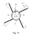
- a modified device 10 is shown in which the clamping rings 40b are pivoted by an angle ⁇ with respect to a arranged at the mounting location of the clamping rings 40b on the sleeve-like element 12, the longitudinal axis 42 intersecting straight line 44. It is essential that the clamping rings 40b, together with the element 12 are formed as a one-piece component as an injection molded part. In addition, it has proved to be advantageous if angle ⁇ between 5 ° and 45 °, preferably between 10 ° and 30 °, very particularly preferably between 15 ° and 20 °.
- Fig. 18 to 20 is one opposite to the one in the Fig. 1 illustrated device 10, not embraced by the invention device 10c shown, which is characterized by the use of a clamping device 100 with a clamping buckle connection 15a, which is designed as a double-joint buckle 70.
- the double-joint buckle 70 comprises a preferably made of plastic retaining bracket 71 which is pivotally connected to a clamping bracket 72 in the region of an axis 73 of the clamping bracket 72.
- the clamping bracket 72 is in turn arranged on the axis 73 remote from the side in an axis 73 parallel to the axis 74 hinged.
- the shaft 74 is disposed at one end portion of the sleeve-like member 12.
- the retaining bracket 71 has an opening 75, which engages in the extension 28 for tensioning the clamping buckle connection 15a.
- the retaining bracket 71 has a holding portion 76 engaging around the axis 73, whose opening 77 has an opening width or an opening gap which is smaller than the diameter of the axis 73.
- the retaining bracket 71 or the retaining portion 76 forms with the axis 73 a latching connection, in which the holding portion 76 engages around the axis 73.
- the device 10b according to the invention described so far can be modified or modified in many ways without deviating from the idea of the invention.
Landscapes
- Engineering & Computer Science (AREA)
- General Engineering & Computer Science (AREA)
- Mechanical Engineering (AREA)
- Clamps And Clips (AREA)
- Mutual Connection Of Rods And Tubes (AREA)
Claims (14)
- Dispositif (10b) pour la fixation temporaire d'une unité de tube (1), en particulier d'une unité de tube (1) constituée d'au moins deux éléments de tube (5 ; 5a) connectés coaxialement l'un à l'autre, l'unité de tube (1) comprenant un élément de type manchette (12) et celui-ci étant pourvu d'au moins un organe (35 ; 40 ; 40a ; 40b) faisant saillie radialement depuis celui-ci, l'élément de type manchette (12) présentant, du côté de la périphérie, deux régions d'extrémité (13, 14) connectées l'une à l'autre en liaison fonctionnelle dans une position de verrouillage, lesquelles constituent ensemble, pour la fixation de l'unité de tube (1) dans la position de verrouillage, un engagement par serrage ou par correspondance de forme avec l'unité de tube (1), les deux régions d'extrémité (13, 14) étant connectées à un dispositif de serrage (100) amplifiant la force d'une force d'actionnement manuelle, et le dispositif de serrage (100) présentant un élément d'actionnement en forme de levier (53), pouvant être actionné sans outil et manuellement pour le serrage du dispositif de serrage (100),
caractérisé en ce que
le dispositif de serrage (100) sert à réaliser une connexion par encliquetage (65) entre les régions d'extrémité (13, 14) de l'élément de type manchette (12), l'élément d'actionnement (53) coopérant en liaison fonctionnelle avec une première géométrie de denture (45) réalisée au niveau d'une région d'extrémité (13) de l'élément de type manchette (12). - Dispositif selon la revendication 1,
caractérisé en ce que
l'élément d'actionnement (53) présente une portion (63) coopérant avec la première géométrie de denture (45), laquelle portion coopère avec la première géométrie de denture (45) à la manière d'un cliquet, de sorte que dans le cas d'un déplacement de l'élément d'actionnement (53) dans une direction, la périphérie de l'élément de type manchette (12) diminue, et que dans le cas d'un déplacement de l'élément d'actionnement (53) dans l'autre direction, l'élément de type manchette (12) conserve sa périphérie. - Dispositif selon la revendication 1 ou 2, caractérisé en ce que
la portion d'extrémité (13) présentant la première géométrie de denture (45) présente, du côté opposé à la première géométrie de denture (45), une deuxième géométrie de denture (46) qui coopère avec une denture conjuguée (50) au niveau de la deuxième portion d'extrémité (14) de l'élément de type manchette (12). - Dispositif selon l'une quelconque des revendications 1 à 3,
caractérisé en ce que
l'élément d'actionnement (53) est réalisé en forme de plaque d'actionnement (52) pouvant pivoter vers l'avant et vers l'arrière. - Dispositif selon la revendication 4,
caractérisé en ce que
la plaque d'actionnement (52) est disposée dans la région d'un organe (40) et est fixée sur celui-ci de manière à pouvoir pivoter. - Dispositif selon la revendication 4,
caractérisé en ce que
l'élément d'actionnement (53) est formé par un organe (40a) qui est connecté par le biais d'une portion de connexion (67) à l'élément de type manchette (12). - Dispositif selon l'une quelconque des revendications 1 à 6,
caractérisé en ce que
plusieurs, de préférence quatre organes (35 ; 40 ; 40a ; 40b) faisant saillie radialement, disposés à intervalles angulaires réguliers les uns par rapport aux autres, sont prévus, et en ce que les organes, considérés dans la direction longitudinale du dispositif, sont réalisés de manière déformable élastiquement et radialement. - Dispositif selon la revendication 7,
caractérisé en ce que
les organes saillants sont réalisés sous forme de bagues de serrage (40 ; 40a), dont les axes longitudinaux (41) s'étendent perpendiculairement à l'axe longitudinal (42) de l'élément de type manchette (12), et en ce que les bagues de serrage (40) sont réalisées sous forme de composants séparés, qui sont connectés par le biais d'une connexion par encliquetage réalisée avec engagement par correspondance de forme avec l'élément de type manchette (12). - Dispositif selon la revendication 7,
caractérisé en ce que
les organes saillants sont réalisés sous forme de bagues de serrage (40b) qui sont pivotées suivant un angle (α) par rapport à une droite (44) coupant l'axe longitudinal (42), disposée au lieu de fixation des bagues de serrage (40b) au niveau de l'élément (12) et en ce que les bagues de serrage (40b), conjointement avec l'élément (12), sont réalisées sous forme de composant d'une seule pièce en tant que pièce moulée par injection. - Dispositif selon la revendication 9,
caractérisé en ce que
l'angle (α) est compris entre 5° et 45°, de préférence entre 10° et 30°, et particulièrement préférablement entre 15° et 20°. - Dispositif selon l'une quelconque des revendications 1 à 10,
caractérisé en ce que
l'élément de type manchette (12) présente une paroi radialement périphérique, et en ce qu'au moins une portion de retenue saillant radialement vers l'intérieur (31, 32) part de la paroi, laquelle portion de retenue constitue, dans la position de verrouillage de la connexion à collier de serrage (15) avec l'unité de tube (1), une connexion par engagement par correspondance de forme, fixant l'unité de tube (1) dans la direction axiale. - Dispositif selon la revendication 11,
caractérisé en ce que
dans la région des deux côtés frontaux de l'élément de type manchette (12), sont prévues plusieurs portions de retenue (31, 32) de type segments partiels, de préférence disposées les unes par rapport aux autres à intervalles angulaires identiques, lesquelles sont à chaque fois réalisées en forme de brides et en ce que les portions de retenue (31, 32) sont disposées de manière décalée radialement les unes par rapport aux autres au niveau des deux côtés frontaux. - Dispositif selon la revendication 12,
caractérisé en ce que
considéré dans la direction longitudinale de l'élément de type manchette (12), des régions dépourvues de portions de retenue (38) sont réalisées, lesquelles s'étendent sur toute l'étendue longitudinale de l'élément de type manchette (12). - Dispositif selon l'une quelconque des revendications 1 à 13,
caractérisé en ce que
l'élément de type manchette (12) et le dispositif de serrage (100) se composent entièrement de plastique.
Priority Applications (1)
| Application Number | Priority Date | Filing Date | Title |
|---|---|---|---|
| EP14163890.8A EP2759752B1 (fr) | 2011-10-19 | 2012-10-02 | Dispositif de fixation d'une unité de tuyau |
Applications Claiming Priority (2)
| Application Number | Priority Date | Filing Date | Title |
|---|---|---|---|
| DE201110054617 DE102011054617A1 (de) | 2011-10-19 | 2011-10-19 | Vorrichtung zum zeitweiligen Befestigen einer Rohreinheit |
| DE201220102981 DE202012102981U1 (de) | 2011-10-19 | 2012-08-08 | Vorrichtung zum Festlegen einer Rohreinheit |
Related Child Applications (2)
| Application Number | Title | Priority Date | Filing Date |
|---|---|---|---|
| EP14163890.8A Division EP2759752B1 (fr) | 2011-10-19 | 2012-10-02 | Dispositif de fixation d'une unité de tuyau |
| EP14163890.8A Division-Into EP2759752B1 (fr) | 2011-10-19 | 2012-10-02 | Dispositif de fixation d'une unité de tuyau |
Publications (3)
| Publication Number | Publication Date |
|---|---|
| EP2584237A2 EP2584237A2 (fr) | 2013-04-24 |
| EP2584237A3 EP2584237A3 (fr) | 2014-03-05 |
| EP2584237B1 true EP2584237B1 (fr) | 2014-12-03 |
Family
ID=47740578
Family Applications (2)
| Application Number | Title | Priority Date | Filing Date |
|---|---|---|---|
| EP20120186991 Not-in-force EP2584237B1 (fr) | 2011-10-19 | 2012-10-02 | Dispositif de fixation d'une unité de tuyau |
| EP14163890.8A Not-in-force EP2759752B1 (fr) | 2011-10-19 | 2012-10-02 | Dispositif de fixation d'une unité de tuyau |
Family Applications After (1)
| Application Number | Title | Priority Date | Filing Date |
|---|---|---|---|
| EP14163890.8A Not-in-force EP2759752B1 (fr) | 2011-10-19 | 2012-10-02 | Dispositif de fixation d'une unité de tuyau |
Country Status (2)
| Country | Link |
|---|---|
| EP (2) | EP2584237B1 (fr) |
| DE (2) | DE102011054617A1 (fr) |
Families Citing this family (4)
| Publication number | Priority date | Publication date | Assignee | Title |
|---|---|---|---|---|
| DE102012112655A1 (de) * | 2012-12-19 | 2014-06-26 | Dieter Bächle | Vorrichtung zum Festlegen einer Rohreinheit |
| DE102019114640A1 (de) * | 2019-05-23 | 2020-11-26 | AS Technologie GmbH | Modulsystem und Verfahren zum Anordnen einer Rohreinheit sowie Rohreinheit |
| EP3742032A1 (fr) | 2019-05-23 | 2020-11-25 | AS Technologie GmbH | Système module et procédé d'agencement d'une unité tubulaire ainsi qu'unité tubulaire |
| CN112663901B (zh) * | 2020-12-10 | 2022-05-06 | 重庆工程职业技术学院 | 一种防火板包裹的一体式排烟管道 |
Family Cites Families (7)
| Publication number | Priority date | Publication date | Assignee | Title |
|---|---|---|---|---|
| DE29618107U1 (de) * | 1996-10-18 | 1996-12-12 | Erlus Baustoffwerke AG, 84088 Neufahrn | Kamin-Fertigbauteil |
| DE20003980U1 (de) * | 2000-03-02 | 2001-07-19 | Tona Tonwerke Schmitz GmbH, 53894 Mechernich | Verbindungsschelle für Kaminrohrelemente mit Muffenenden und Einsteckenden für Muffensteckverbindungen |
| US6588802B2 (en) * | 2001-06-22 | 2003-07-08 | Fred G. Schukal | Two-part, clamp-connected chimney flue tee |
| DE10205989C1 (de) * | 2002-02-14 | 2003-09-25 | Guenter Sykosch | Halterung für Leitungen und Schachtführungen |
| DE10340903A1 (de) * | 2003-09-02 | 2005-03-17 | Bächle, Dieter | Vorrichtung zum Festlegen von Rohren für den Wärmehaushalt in Gebäuden |
| DE202006015501U1 (de) * | 2005-10-28 | 2007-02-01 | Bächle, Dieter | Vorrichtung zum zeitweiligen Befestigen einer Rohreinheit |
| DE202007017476U1 (de) | 2006-10-19 | 2008-04-03 | Bächle, Dieter | Vorrichtung zum zeitweiligen Befestigen einer Rohreinheit |
-
2011
- 2011-10-19 DE DE201110054617 patent/DE102011054617A1/de not_active Withdrawn
-
2012
- 2012-08-08 DE DE201220102981 patent/DE202012102981U1/de not_active Expired - Lifetime
- 2012-10-02 EP EP20120186991 patent/EP2584237B1/fr not_active Not-in-force
- 2012-10-02 EP EP14163890.8A patent/EP2759752B1/fr not_active Not-in-force
Also Published As
| Publication number | Publication date |
|---|---|
| DE102011054617A1 (de) | 2013-04-25 |
| DE202012102981U1 (de) | 2013-01-21 |
| EP2759752A1 (fr) | 2014-07-30 |
| EP2584237A2 (fr) | 2013-04-24 |
| EP2759752B1 (fr) | 2015-07-22 |
| EP2584237A3 (fr) | 2014-03-05 |
Similar Documents
| Publication | Publication Date | Title |
|---|---|---|
| EP2765342B1 (fr) | Collier de serrage profilé avec pré-positionneur | |
| EP1260751A2 (fr) | Collier de serrage, notamment raccord de tuyaux | |
| DE102011005598A1 (de) | Befestigungsvorrichtung zur Anordnung an einer Montageschiene | |
| EP2584237B1 (fr) | Dispositif de fixation d'une unité de tuyau | |
| DE102009009990A1 (de) | Schutzschlauch-/-Rohr-Schnellverschraubung | |
| WO2017194419A1 (fr) | Segment en demi-anneau, pince de raccordement et disposisitf de raccordement | |
| DE102012102545B4 (de) | Kupplungseinrichtung zum Verbinden zweier Frischluftrohre für eine Heizungsanlage | |
| EP2737241B1 (fr) | Élément de fermeture pour extrémités de tubes | |
| EP2746663B1 (fr) | Dispositif de fixation d'un tuyau | |
| EP2869417B1 (fr) | Dispositif de liaison de sections de conduit de câble et conduit de câble | |
| EP2581637B1 (fr) | Couvercle de fermeture destiné à fermer un orifice de contrôle sur un tuyau d'échappement en matière synthétique, tuyau d'échappement et système avec un couvercle de fermeture | |
| DE102016107159A1 (de) | Anschlussvorrichtung | |
| DE102004032053B4 (de) | Rohrschelle mit integriertem Rast-Verschluss | |
| EP1256754B1 (fr) | Collier de serrage | |
| EP3306763A1 (fr) | Dispositif pour installations électriques | |
| EP3064849A1 (fr) | Systeme de distribution, en particulier diffuseur d'air | |
| DE102013104041B4 (de) | Spanneinrichtung für eine Abgasrohreinheit einer Heizungsanlage, Einheit mit einer Spanneinrichtung und Abgasrohrsystem | |
| DE102015000490A1 (de) | Befestigungselement | |
| EP3584500B1 (fr) | Bride tubulaire pour tuyaux d'air de combustion ainsi que système de gaz d'échappement | |
| EP3608571B1 (fr) | Système de raccordement | |
| EP1722145A2 (fr) | Elément tubulaire avec élément de protection | |
| EP0388663B1 (fr) | Collier pour tuyaux | |
| EP2910833B1 (fr) | Dispositif de liaison de conduits | |
| AT16957U1 (fr) | ||
| EP1188980B1 (fr) | Raccord de soudage |
Legal Events
| Date | Code | Title | Description |
|---|---|---|---|
| PUAI | Public reference made under article 153(3) epc to a published international application that has entered the european phase |
Free format text: ORIGINAL CODE: 0009012 |
|
| AK | Designated contracting states |
Kind code of ref document: A2 Designated state(s): AL AT BE BG CH CY CZ DE DK EE ES FI FR GB GR HR HU IE IS IT LI LT LU LV MC MK MT NL NO PL PT RO RS SE SI SK SM TR |
|
| AX | Request for extension of the european patent |
Extension state: BA ME |
|
| RAP1 | Party data changed (applicant data changed or rights of an application transferred) |
Owner name: BAECHLE, DIETER |
|
| RIN1 | Information on inventor provided before grant (corrected) |
Inventor name: BAECHLE, DIETER |
|
| PUAL | Search report despatched |
Free format text: ORIGINAL CODE: 0009013 |
|
| AK | Designated contracting states |
Kind code of ref document: A3 Designated state(s): AL AT BE BG CH CY CZ DE DK EE ES FI FR GB GR HR HU IE IS IT LI LT LU LV MC MK MT NL NO PL PT RO RS SE SI SK SM TR |
|
| AX | Request for extension of the european patent |
Extension state: BA ME |
|
| RIC1 | Information provided on ipc code assigned before grant |
Ipc: F16L 7/00 20060101AFI20140127BHEP Ipc: E04F 17/02 20060101ALI20140127BHEP Ipc: F23J 13/04 20060101ALI20140127BHEP |
|
| 17P | Request for examination filed |
Effective date: 20140408 |
|
| RBV | Designated contracting states (corrected) |
Designated state(s): AL AT BE BG CH CY CZ DE DK EE ES FI FR GB GR HR HU IE IS IT LI LT LU LV MC MK MT NL NO PL PT RO RS SE SI SK SM TR |
|
| GRAP | Despatch of communication of intention to grant a patent |
Free format text: ORIGINAL CODE: EPIDOSNIGR1 |
|
| INTG | Intention to grant announced |
Effective date: 20140701 |
|
| GRAS | Grant fee paid |
Free format text: ORIGINAL CODE: EPIDOSNIGR3 |
|
| GRAA | (expected) grant |
Free format text: ORIGINAL CODE: 0009210 |
|
| AK | Designated contracting states |
Kind code of ref document: B1 Designated state(s): AL AT BE BG CH CY CZ DE DK EE ES FI FR GB GR HR HU IE IS IT LI LT LU LV MC MK MT NL NO PL PT RO RS SE SI SK SM TR |
|
| REG | Reference to a national code |
Ref country code: GB Ref legal event code: FG4D Free format text: NOT ENGLISH |
|
| REG | Reference to a national code |
Ref country code: AT Ref legal event code: REF Ref document number: 699568 Country of ref document: AT Kind code of ref document: T Effective date: 20141215 Ref country code: CH Ref legal event code: EP |
|
| REG | Reference to a national code |
Ref country code: IE Ref legal event code: FG4D Free format text: LANGUAGE OF EP DOCUMENT: GERMAN |
|
| REG | Reference to a national code |
Ref country code: DE Ref legal event code: R096 Ref document number: 502012001724 Country of ref document: DE Effective date: 20150115 |
|
| REG | Reference to a national code |
Ref country code: NL Ref legal event code: VDEP Effective date: 20141203 |
|
| PG25 | Lapsed in a contracting state [announced via postgrant information from national office to epo] |
Ref country code: NO Free format text: LAPSE BECAUSE OF FAILURE TO SUBMIT A TRANSLATION OF THE DESCRIPTION OR TO PAY THE FEE WITHIN THE PRESCRIBED TIME-LIMIT Effective date: 20150303 Ref country code: FI Free format text: LAPSE BECAUSE OF FAILURE TO SUBMIT A TRANSLATION OF THE DESCRIPTION OR TO PAY THE FEE WITHIN THE PRESCRIBED TIME-LIMIT Effective date: 20141203 Ref country code: ES Free format text: LAPSE BECAUSE OF FAILURE TO SUBMIT A TRANSLATION OF THE DESCRIPTION OR TO PAY THE FEE WITHIN THE PRESCRIBED TIME-LIMIT Effective date: 20141203 Ref country code: NL Free format text: LAPSE BECAUSE OF FAILURE TO SUBMIT A TRANSLATION OF THE DESCRIPTION OR TO PAY THE FEE WITHIN THE PRESCRIBED TIME-LIMIT Effective date: 20141203 Ref country code: LT Free format text: LAPSE BECAUSE OF FAILURE TO SUBMIT A TRANSLATION OF THE DESCRIPTION OR TO PAY THE FEE WITHIN THE PRESCRIBED TIME-LIMIT Effective date: 20141203 |
|
| REG | Reference to a national code |
Ref country code: LT Ref legal event code: MG4D |
|
| PG25 | Lapsed in a contracting state [announced via postgrant information from national office to epo] |
Ref country code: CY Free format text: LAPSE BECAUSE OF FAILURE TO SUBMIT A TRANSLATION OF THE DESCRIPTION OR TO PAY THE FEE WITHIN THE PRESCRIBED TIME-LIMIT Effective date: 20141203 Ref country code: GR Free format text: LAPSE BECAUSE OF FAILURE TO SUBMIT A TRANSLATION OF THE DESCRIPTION OR TO PAY THE FEE WITHIN THE PRESCRIBED TIME-LIMIT Effective date: 20150304 Ref country code: HR Free format text: LAPSE BECAUSE OF FAILURE TO SUBMIT A TRANSLATION OF THE DESCRIPTION OR TO PAY THE FEE WITHIN THE PRESCRIBED TIME-LIMIT Effective date: 20141203 Ref country code: RS Free format text: LAPSE BECAUSE OF FAILURE TO SUBMIT A TRANSLATION OF THE DESCRIPTION OR TO PAY THE FEE WITHIN THE PRESCRIBED TIME-LIMIT Effective date: 20141203 Ref country code: SE Free format text: LAPSE BECAUSE OF FAILURE TO SUBMIT A TRANSLATION OF THE DESCRIPTION OR TO PAY THE FEE WITHIN THE PRESCRIBED TIME-LIMIT Effective date: 20141203 Ref country code: LV Free format text: LAPSE BECAUSE OF FAILURE TO SUBMIT A TRANSLATION OF THE DESCRIPTION OR TO PAY THE FEE WITHIN THE PRESCRIBED TIME-LIMIT Effective date: 20141203 |
|
| PG25 | Lapsed in a contracting state [announced via postgrant information from national office to epo] |
Ref country code: CZ Free format text: LAPSE BECAUSE OF FAILURE TO SUBMIT A TRANSLATION OF THE DESCRIPTION OR TO PAY THE FEE WITHIN THE PRESCRIBED TIME-LIMIT Effective date: 20141203 Ref country code: SK Free format text: LAPSE BECAUSE OF FAILURE TO SUBMIT A TRANSLATION OF THE DESCRIPTION OR TO PAY THE FEE WITHIN THE PRESCRIBED TIME-LIMIT Effective date: 20141203 Ref country code: EE Free format text: LAPSE BECAUSE OF FAILURE TO SUBMIT A TRANSLATION OF THE DESCRIPTION OR TO PAY THE FEE WITHIN THE PRESCRIBED TIME-LIMIT Effective date: 20141203 Ref country code: PT Free format text: LAPSE BECAUSE OF FAILURE TO SUBMIT A TRANSLATION OF THE DESCRIPTION OR TO PAY THE FEE WITHIN THE PRESCRIBED TIME-LIMIT Effective date: 20150403 Ref country code: RO Free format text: LAPSE BECAUSE OF FAILURE TO SUBMIT A TRANSLATION OF THE DESCRIPTION OR TO PAY THE FEE WITHIN THE PRESCRIBED TIME-LIMIT Effective date: 20141203 |
|
| PG25 | Lapsed in a contracting state [announced via postgrant information from national office to epo] |
Ref country code: PL Free format text: LAPSE BECAUSE OF FAILURE TO SUBMIT A TRANSLATION OF THE DESCRIPTION OR TO PAY THE FEE WITHIN THE PRESCRIBED TIME-LIMIT Effective date: 20141203 Ref country code: IS Free format text: LAPSE BECAUSE OF FAILURE TO SUBMIT A TRANSLATION OF THE DESCRIPTION OR TO PAY THE FEE WITHIN THE PRESCRIBED TIME-LIMIT Effective date: 20150403 |
|
| REG | Reference to a national code |
Ref country code: DE Ref legal event code: R097 Ref document number: 502012001724 Country of ref document: DE |
|
| PLBE | No opposition filed within time limit |
Free format text: ORIGINAL CODE: 0009261 |
|
| STAA | Information on the status of an ep patent application or granted ep patent |
Free format text: STATUS: NO OPPOSITION FILED WITHIN TIME LIMIT |
|
| PG25 | Lapsed in a contracting state [announced via postgrant information from national office to epo] |
Ref country code: DK Free format text: LAPSE BECAUSE OF FAILURE TO SUBMIT A TRANSLATION OF THE DESCRIPTION OR TO PAY THE FEE WITHIN THE PRESCRIBED TIME-LIMIT Effective date: 20141203 |
|
| 26N | No opposition filed |
Effective date: 20150904 |
|
| PG25 | Lapsed in a contracting state [announced via postgrant information from national office to epo] |
Ref country code: IT Free format text: LAPSE BECAUSE OF FAILURE TO SUBMIT A TRANSLATION OF THE DESCRIPTION OR TO PAY THE FEE WITHIN THE PRESCRIBED TIME-LIMIT Effective date: 20141203 |
|
| PG25 | Lapsed in a contracting state [announced via postgrant information from national office to epo] |
Ref country code: SI Free format text: LAPSE BECAUSE OF FAILURE TO SUBMIT A TRANSLATION OF THE DESCRIPTION OR TO PAY THE FEE WITHIN THE PRESCRIBED TIME-LIMIT Effective date: 20141203 |
|
| PG25 | Lapsed in a contracting state [announced via postgrant information from national office to epo] |
Ref country code: LU Free format text: LAPSE BECAUSE OF FAILURE TO SUBMIT A TRANSLATION OF THE DESCRIPTION OR TO PAY THE FEE WITHIN THE PRESCRIBED TIME-LIMIT Effective date: 20151002 |
|
| REG | Reference to a national code |
Ref country code: CH Ref legal event code: PL |
|
| PG25 | Lapsed in a contracting state [announced via postgrant information from national office to epo] |
Ref country code: MC Free format text: LAPSE BECAUSE OF FAILURE TO SUBMIT A TRANSLATION OF THE DESCRIPTION OR TO PAY THE FEE WITHIN THE PRESCRIBED TIME-LIMIT Effective date: 20141203 |
|
| REG | Reference to a national code |
Ref country code: IE Ref legal event code: MM4A |
|
| PG25 | Lapsed in a contracting state [announced via postgrant information from national office to epo] |
Ref country code: CH Free format text: LAPSE BECAUSE OF NON-PAYMENT OF DUE FEES Effective date: 20151031 Ref country code: LI Free format text: LAPSE BECAUSE OF NON-PAYMENT OF DUE FEES Effective date: 20151031 |
|
| REG | Reference to a national code |
Ref country code: FR Ref legal event code: ST Effective date: 20160630 |
|
| PG25 | Lapsed in a contracting state [announced via postgrant information from national office to epo] |
Ref country code: FR Free format text: LAPSE BECAUSE OF NON-PAYMENT OF DUE FEES Effective date: 20151102 |
|
| PG25 | Lapsed in a contracting state [announced via postgrant information from national office to epo] |
Ref country code: IE Free format text: LAPSE BECAUSE OF NON-PAYMENT OF DUE FEES Effective date: 20151002 |
|
| PG25 | Lapsed in a contracting state [announced via postgrant information from national office to epo] |
Ref country code: HU Free format text: LAPSE BECAUSE OF FAILURE TO SUBMIT A TRANSLATION OF THE DESCRIPTION OR TO PAY THE FEE WITHIN THE PRESCRIBED TIME-LIMIT; INVALID AB INITIO Effective date: 20121002 Ref country code: BG Free format text: LAPSE BECAUSE OF FAILURE TO SUBMIT A TRANSLATION OF THE DESCRIPTION OR TO PAY THE FEE WITHIN THE PRESCRIBED TIME-LIMIT Effective date: 20141203 Ref country code: SM Free format text: LAPSE BECAUSE OF FAILURE TO SUBMIT A TRANSLATION OF THE DESCRIPTION OR TO PAY THE FEE WITHIN THE PRESCRIBED TIME-LIMIT Effective date: 20141203 |
|
| GBPC | Gb: european patent ceased through non-payment of renewal fee |
Effective date: 20161002 |
|
| PG25 | Lapsed in a contracting state [announced via postgrant information from national office to epo] |
Ref country code: BE Free format text: LAPSE BECAUSE OF NON-PAYMENT OF DUE FEES Effective date: 20151031 Ref country code: GB Free format text: LAPSE BECAUSE OF NON-PAYMENT OF DUE FEES Effective date: 20161002 |
|
| PG25 | Lapsed in a contracting state [announced via postgrant information from national office to epo] |
Ref country code: MT Free format text: LAPSE BECAUSE OF FAILURE TO SUBMIT A TRANSLATION OF THE DESCRIPTION OR TO PAY THE FEE WITHIN THE PRESCRIBED TIME-LIMIT Effective date: 20141203 |
|
| PG25 | Lapsed in a contracting state [announced via postgrant information from national office to epo] |
Ref country code: MK Free format text: LAPSE BECAUSE OF FAILURE TO SUBMIT A TRANSLATION OF THE DESCRIPTION OR TO PAY THE FEE WITHIN THE PRESCRIBED TIME-LIMIT Effective date: 20141203 Ref country code: TR Free format text: LAPSE BECAUSE OF FAILURE TO SUBMIT A TRANSLATION OF THE DESCRIPTION OR TO PAY THE FEE WITHIN THE PRESCRIBED TIME-LIMIT Effective date: 20141203 |
|
| PG25 | Lapsed in a contracting state [announced via postgrant information from national office to epo] |
Ref country code: AL Free format text: LAPSE BECAUSE OF FAILURE TO SUBMIT A TRANSLATION OF THE DESCRIPTION OR TO PAY THE FEE WITHIN THE PRESCRIBED TIME-LIMIT Effective date: 20141203 |
|
| REG | Reference to a national code |
Ref country code: AT Ref legal event code: MM01 Ref document number: 699568 Country of ref document: AT Kind code of ref document: T Effective date: 20171002 |
|
| PG25 | Lapsed in a contracting state [announced via postgrant information from national office to epo] |
Ref country code: AT Free format text: LAPSE BECAUSE OF NON-PAYMENT OF DUE FEES Effective date: 20171002 |
|
| PGFP | Annual fee paid to national office [announced via postgrant information from national office to epo] |
Ref country code: DE Payment date: 20181029 Year of fee payment: 7 |
|
| REG | Reference to a national code |
Ref country code: DE Ref legal event code: R119 Ref document number: 502012001724 Country of ref document: DE |
|
| PG25 | Lapsed in a contracting state [announced via postgrant information from national office to epo] |
Ref country code: DE Free format text: LAPSE BECAUSE OF NON-PAYMENT OF DUE FEES Effective date: 20200501 |