EP2584098A1 - Verfahren zum Anwenden einer vorspannenden Kraft auf einen Ankerbolzen - Google Patents
Verfahren zum Anwenden einer vorspannenden Kraft auf einen Ankerbolzen Download PDFInfo
- Publication number
- EP2584098A1 EP2584098A1 EP12188857.2A EP12188857A EP2584098A1 EP 2584098 A1 EP2584098 A1 EP 2584098A1 EP 12188857 A EP12188857 A EP 12188857A EP 2584098 A1 EP2584098 A1 EP 2584098A1
- Authority
- EP
- European Patent Office
- Prior art keywords
- tightening force
- anchor bolt
- applying
- anchor
- tensioner
- Prior art date
- Legal status (The legal status is an assumption and is not a legal conclusion. Google has not performed a legal analysis and makes no representation as to the accuracy of the status listed.)
- Withdrawn
Links
- 238000000034 method Methods 0.000 title claims abstract description 35
- 239000000049 pigment Substances 0.000 claims description 4
- 238000009434 installation Methods 0.000 abstract description 13
- 239000003973 paint Substances 0.000 abstract description 5
- 238000010586 diagram Methods 0.000 description 13
- 238000012986 modification Methods 0.000 description 2
- 230000004048 modification Effects 0.000 description 2
- 230000000630 rising effect Effects 0.000 description 2
- 229910000831 Steel Inorganic materials 0.000 description 1
- 239000000853 adhesive Substances 0.000 description 1
- 230000001070 adhesive effect Effects 0.000 description 1
- 238000007796 conventional method Methods 0.000 description 1
- 239000002184 metal Substances 0.000 description 1
- 230000000149 penetrating effect Effects 0.000 description 1
- 239000010959 steel Substances 0.000 description 1
Images


Classifications
-
- E—FIXED CONSTRUCTIONS
- E02—HYDRAULIC ENGINEERING; FOUNDATIONS; SOIL SHIFTING
- E02D—FOUNDATIONS; EXCAVATIONS; EMBANKMENTS; UNDERGROUND OR UNDERWATER STRUCTURES
- E02D27/00—Foundations as substructures
- E02D27/32—Foundations for special purposes
- E02D27/42—Foundations for poles, masts or chimneys
-
- Y—GENERAL TAGGING OF NEW TECHNOLOGICAL DEVELOPMENTS; GENERAL TAGGING OF CROSS-SECTIONAL TECHNOLOGIES SPANNING OVER SEVERAL SECTIONS OF THE IPC; TECHNICAL SUBJECTS COVERED BY FORMER USPC CROSS-REFERENCE ART COLLECTIONS [XRACs] AND DIGESTS
- Y10—TECHNICAL SUBJECTS COVERED BY FORMER USPC
- Y10T—TECHNICAL SUBJECTS COVERED BY FORMER US CLASSIFICATION
- Y10T29/00—Metal working
- Y10T29/49—Method of mechanical manufacture
- Y10T29/49826—Assembling or joining
- Y10T29/49863—Assembling or joining with prestressing of part
Definitions
- the present invention relates to mechanical technology, and particularly to a method of applying a pre-tightening force on an anchor bolt.
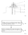
- the steel tower of wind turbine is generally fixed with embedded fasteners, taking the conventional embedded bolts for example, the tower is fixed as follows: part of an anchor bolt 1 is embedded in concrete 16, the rest protrudes from the concrete 16; one end of the anchor bolt 1 in the concrete 16 is screwed on with a fixing nut 2; the part of the anchor bolt 1 protruding from the concrete 16 penetrates through a shimming flange 3 and a tower flange 4 from bottom to top after penetrating through the concrete 16, then is screwed on with a fixing nut 5, and the specific schematic diagram is as shown in FIG.1 .
- the axial force subjected to by an anchor bolt should be equal to a predetermined pre-tightening force.
- a tensioner is used to pre-tighten the anchor bolts one by one.
- the anchor bolts installed at the bottom of the tower generally are arranged in an inner ring and an outer ring, taking 96 anchor bolts in each of the rings for example, there are 192 anchor bolts in total.
- the tensioner comprises a supporting bridge, a telescopic boom and a stretching head. In use, the supporting bridge is disposed on tower flange, and the stretching head and the top of the anchor bolt are fixed. The telescopic boom protrudes against the stretching head and drives the anchor bolt to stretch upwards.
- the tensioner works powered by an oil pump.
- the supporting bridge of tensioner is directly disposed on the tower flange, which is easy to damage paint on the surface of the tower flange and thus influences the quality and service life of the tower.
- An object of the present invention is to provide a method of applying a pre-tightening force on an anchor bolt, aiming to optimize the conventional method of applying a pre-tightening force on an anchor bolt and improve performance of the tower.
- One aspect of the present invention provides a method of applying a pre-tightening force on an anchor bolt, comprising:
- the above method of applying a pre-tightening force on an anchor bolt preferably, before installing the washer with a predetermined dimension between the tower flange and the fastening nut for supporting the supporting bridge of the tensioner, further comprising:
- the step of applying a pre-tightening force on anchor bolts in an inner ring and an outer ring installed on the tower flange comprises:
- the step of numbering the anchor bolts in each of the rings comprises:
- the step of recording the serial number of each anchor bolt comprises:
- the method of applying a pre-tightening force on an anchor bolt adopts a washer with a predetermined dimension to replace the conventional washer, such that the tensioner will not directly contact the surface of the tower flange, and the pressure of the tensioner is transmitted uniformly to the tower flange via the washer, avoiding damage to paint on the surface of the tower flange and improving installation quality and service life of the tower.
- FIG.1 is a partial installation schematic diagram of the tower in the prior art
- FIG.2a is a flow schematic diagram of the method of applying a pre-tightening force on an anchor bolt according to Embodiment 1 of the present invention
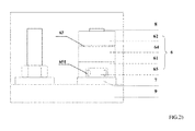
- FIG.2b is an installation schematic diagram of the tensioner according to Embodiment 1 of the present invention
- FIG.3a is a flow schematic diagram of the method of applying a pre-tightening force on an anchor bolt according to Embodiment 2 of the present invention
- FIG.3b is a schematic diagram of numbering the anchor bolts according to Embodiment 2 of the present invention
- FIG.3c is a schematic diagram of the tensioners in series according to Embodiment 2 of the present invention.
- Embodiment 1 of the present invention provides a method of applying a pre-tightening force on an anchor bolt, the method is typically suitable for pre-tightening anchor bolts on wind turbine generator system (WTGS) as shown in FIG.1 , the flow schematic diagram of the method is shown in FIG.2a , and the installation schematic diagram of the tensioner is shown in FIG.2b .
- the method comprises the following steps:
- Step 110 installing a washer 7 with a predetermined dimension between a tower flange 9 and a fastening nut, wherein the washer 7 is configured to support a supporting bridge 61 of a tensioner 6.
- the dimension of the washer 7 can be greater than, less than or equal to the dimension of the supporting bridge 61 of the tensioner 6, however, in order to reduce the pressure subjected to by the washer 7, preferably, the predetermined dimension of the washer 7 is the radial dimension of the washer 7, which is greater than the radial dimension of the supporting bridge 61 of the tensioner 6.
- the radial dimension of the washer is greater than the radial dimension of the supporting bridge of the tensioner, such that the supporting bridge of the tensioner can be disposed on the washer in a convenient way.
- the washer should be as thick as possible, here, the thickness can be 15mm-30mm.
- selecting washer with greater width and thickness can also make the supporting surface of the tensioner's supporting bridge fully supported on the washer, the washer can transmit uniformly pressure of the tensioner to the tower flange, thus avoiding damage to paint on the surface of the tower flange and improving installation quality and service life of the tower.
- a conventional tensioner can be used.
- the washer 7 should be made of metal.
- Step 120 applying a pre-tightening force on anchor bolts 8 arranged in an inner ring and in an outer ring installed on the tower flange 9 with the tensioners 6.
- the length of the anchor bolt 8 clamped by stretching head 62 of the tensioner 6 is no less than 1.5 times of the diameter of the anchor bolt 8. In this way, the connection between the stretching head 62 and anchor bolt 8 is more reliable.
- the installation schematic diagram of the tensioner is as shown in FIG.2b , when the tensioner 6 is used, the supporting bridge 61 of the tensioner 6 is disposed on the washer 7, the tower flange 9 is under the washer 7, the stretching head 62 of the tensioner 6 is fixed to the top portion of the anchor bolt 8, a shifting ring 65 of the tensioner 6 surrounds the outside of a fastening nut (not shown), a telescopic boom 63 of the tensioner 6 protrudes when driven by an oil cylinder 64, not only stretching the anchor bolt 8, but also applying a pre-tightening force on the anchor bolt 8. There are six through-holes 651 in the shifting ring 65, and the fastening nut can be rotated via the through-holes 651.
- the force applied by the tensioner 6 on the anchor bolt 8 is mainly axial force, since there is no torque, the anchor bolt 8 will not rotate due to torque, thereby avoiding damage to the concrete layer and influence on installation safety of the tower.
- the method of applying a pre-tightening force on an anchor bolt adopts a washer with a predetermined dimension to replace the conventional washer, such that the tensioner will not directly contact the surface of the tower flange, avoiding damage to paint on the surface of the tower flange and improving installation quality and service life of the tower.
- FIG.3a is a flow schematic diagram of the method of applying a pre-tightening force on an anchor bolt according to Embodiment 2 of the present invention.
- Embodiment 2 of the present invention preferably, prior to Step 110, further comprises the following steps:
- Step 221 numbering anchor bolts 8 in each of the rings, and recording a serial number of each anchor bolt 8, wherein, the anchor bolts 8 in each of the rings are equally divided into at least two groups, the number of the anchor bolts 8 in each group is N, and N is a natural number.
- the schematic diagram of the numbered anchor bolts is as shown in FIG.3b .
- anchor bolts are numbered before the tower is hoisted, and particularly, the numbering manner is as follows: numbering the anchor bolt right facing the tower door of the tower in each of the rings as "1 ", and numbering successively all the anchor bolts in each of the rings in the clockwise direction.
- Embodiments of the present invention take two rings of anchor bolts and 96 anchor bolts in each of the rings as an example. Numbering anchor bolts facilitates to record the working process, thus improving working efficiency and avoiding missing some anchor bolts or repeating operations on some anchor bolts.
- marking the serial number on the anchor bolt with pigment, and the pigment should be those with strong adhesive force, not easy to fade and waterproof.
- Step 120 comprises the following steps:
- Step 222 according to the serial number, applying a pre-tightening force on the i-th anchor bolt 8 in each group simultaneously until all the anchor bolts 8 in each group have been applied with a pre-tightening force equal to about half of a predetermined value, wherein, 1 ⁇ i ⁇ N.
- the anchor bolts in the inner ring with serial numbers of "1 ", “33”, “65” and in the outer ring with serial numbers of "1", “33”, “65” are applied simultaneously with a pre-tightening force equal to about half of the predetermined value; then the anchor bolts in the inner and outer rings with serial numbers of "2", “34”, “66” are applied simultaneously with a pre-tightening force equal to about half of the predetermined value; likewise, until the anchor bolts in the inner and outer rings with serial numbers of "32", “64”, “96” are applied simultaneously with a pre-tightening force equal to about half of the predetermined value.
- the manner of simultaneously applying a pre-tightening force in each group can make the tower flange and shimming flange in close contact, eliminate partial gaps, improve fixing reliability of the tower and ensure the safety of the tower. Since the pre-tightening force cannot be applied on the anchor bolts with a torque spanner, by numbering the anchor bolts, the pre-tightening force can be applied according to the requirements so as to avoid skipping, missing, or repeating applying force to the anchor bolts and the like, and influencing installation quality of the tower. Furthermore, numbering the anchor bolts also facilitates the subsequent checking on the applied pre-tightening force on the bolts, when there are problems on the bolts, the crux of the problem can be found by reviewing the applying process according to the applying record.
- Step 223 according to the serial number, applying a pre-tightening force on the i-th anchor bolt in each group simultaneously until all the anchor bolts in each group have been applied with a pre-tightening force of the predetermined value, wherein, 1 ⁇ i ⁇ N.
- Step 223 has the same principles with Step 222, and unnecessary details are not given here.
- the operations of applying a pre-tightening force on an anchor bolt are divided into two steps, firstly, the anchor bolts are applied with a pre-tightening force equal to about half of the predetermined value, then the anchor bolts are applied with a pre-tightening force of the predetermined value, and such manner of applying force is more reasonable, preventing anchor bolts from being distorted due to being subjected to too much pre-tightening force at a time.
- the number of tensioners 6 equals to the product of the number of groups of the anchor bolts 8 in each of the rings and the number of rings, and tensioners 6 used in each of the rings is connected in series.
- the schematic diagram of the tensioners in series is as shown in FIG.3c , anchor bolts 8 in an inner ring and an outer ring are divided by tower wall 10, and the relative position relationship of shimming flange 11 and tower flange 9 is as shown in FIG.3c .
- Tensioners 6 are connected to an oil pump 13 via an oil pipe 12.
- anchor bolts 8 are divided into six groups, and the inner ring and the outer ring each has three groups, three tensioners 6 used in the inner ring are connected in series while three tensioners 6 used in the outer ring are connected in series. Since oil pipes of tensioners 6 have slight distortion when oil pressure in oil pipes rises, such distortion will reduce the rising speed of oil pressure and such influence becomes more significant as the pipeline becomes longer.
- the tensioners 6 are connected by means of two-path series connection, that is, several tensioners 6 for tensioning anchor bolts 8 in the outer ring are connected in series in one group, while several tensioners 6 for tensioning anchor bolts 8 in the inner ring are connected in series in another group, and two paths of oil pipes are connected to oil pump 13 via a distributor.
- two-path series connection that is, several tensioners 6 for tensioning anchor bolts 8 in the outer ring are connected in series in one group, while several tensioners 6 for tensioning anchor bolts 8 in the inner ring are connected in series in another group, and two paths of oil pipes are connected to oil pump 13 via a distributor.
- the rest five oil pipes have a maximum length of approximately 1/3 of the tower perimeter.
- Oil pump can be disposed on the ground outside the tower door, for convenience of observation and signal liaison of the operators.
- Stretching bolts in this method needs seven workers, that is, six operators for tensioner and one operator for oil pump. In this way, the length of pipelines for connecting the tensioners is reduced, rising speed of pressure in oil pump is increased, working intensity of oil pump is reduced and working efficiency of tensioning anchor bolts is improved.
- the pre-tightening force of anchor bolts should be checked one by one in half a year, one year and two years, the checking sequence for the pre-tightening force should also be done according to the numbering sequence of the bolts. Thereafter, a sample of 10% of the bolts is randomly selected for checking the pre-tightening force every year to make sure the bolts have no loss in the pre-tightening force. All the checking work should have written records for review.
- the method of applying a pre-tightening force on an anchor bolt divides the anchor bolts into groups and applies a pre-tightening force on certain anchor bolt in each group simultaneously, effectively ensuring that each anchor bolt has been applied with a pre-tightening force. Furthermore, the pre-tightening force can be applied two times, firstly applying a pre-tightening force equal to about half of a predetermined value, and then applying a pre-tightening force of the predetermined value, thus avoiding gaps between the tower flange and the shimming flange and ensuring installation reliability of the tower.
Landscapes
- Engineering & Computer Science (AREA)
- Life Sciences & Earth Sciences (AREA)
- General Life Sciences & Earth Sciences (AREA)
- Mining & Mineral Resources (AREA)
- Paleontology (AREA)
- Civil Engineering (AREA)
- General Engineering & Computer Science (AREA)
- Structural Engineering (AREA)
- Piles And Underground Anchors (AREA)
- Wind Motors (AREA)
- Bridges Or Land Bridges (AREA)
- Foundations (AREA)
Applications Claiming Priority (1)
| Application Number | Priority Date | Filing Date | Title |
|---|---|---|---|
| CN201110313649.5A CN103042502B (zh) | 2011-10-17 | 2011-10-17 | 地脚螺栓预紧力施加方法 |
Publications (1)
| Publication Number | Publication Date |
|---|---|
| EP2584098A1 true EP2584098A1 (de) | 2013-04-24 |
Family
ID=47115402
Family Applications (1)
| Application Number | Title | Priority Date | Filing Date |
|---|---|---|---|
| EP12188857.2A Withdrawn EP2584098A1 (de) | 2011-10-17 | 2012-10-17 | Verfahren zum Anwenden einer vorspannenden Kraft auf einen Ankerbolzen |
Country Status (6)
| Country | Link |
|---|---|
| US (1) | US20130091685A1 (de) |
| EP (1) | EP2584098A1 (de) |
| CN (1) | CN103042502B (de) |
| AU (1) | AU2012241154A1 (de) |
| BR (1) | BR102012026589A2 (de) |
| CA (1) | CA2792695A1 (de) |
Families Citing this family (14)
| Publication number | Priority date | Publication date | Assignee | Title |
|---|---|---|---|---|
| WO2013156632A1 (es) * | 2012-02-28 | 2013-10-24 | Ms Enertech, S.L. | Conexión entre una torre de un aerogenerador y su cimentación |
| CN103353907A (zh) * | 2013-06-17 | 2013-10-16 | 沈阳华创风能有限公司 | 一种法兰连接螺栓极限强度校核的计算方法 |
| CN105485138B (zh) * | 2014-10-09 | 2019-12-20 | 遵义遵宏螺杆厂 | 一种预紧螺栓组件 |
| CN104596691B (zh) * | 2014-11-24 | 2017-01-18 | 宝鸡石油机械有限责任公司 | 一种测试水下金属密封垫环预紧力的方法 |
| CN107039897A (zh) * | 2017-06-20 | 2017-08-11 | 四川电力设计咨询有限责任公司 | 电气屏柜的安装结构及安装方法 |
| ES2775069B2 (es) * | 2017-12-27 | 2021-06-23 | Nabrawind Tech Sl | Sistema de control del pretensado de pernos |
| CN110410398B (zh) * | 2019-08-21 | 2024-08-27 | 中冶天工集团天津有限公司 | 一种地脚螺栓紧固装置及其使用方法 |
| CN111719710A (zh) * | 2020-06-01 | 2020-09-29 | 中国核工业华兴建设有限公司 | 一种核电站地脚锚栓成组张拉装置及方法 |
| CN112091589B (zh) * | 2020-09-18 | 2022-07-01 | 一重集团大连核电石化有限公司 | 大直径密集螺栓的紧固方法 |
| CN112179556B (zh) * | 2020-09-29 | 2024-09-10 | 核工业西南物理研究院 | 一种聚变堆螺栓组预紧检测装置及其预紧力检测方法 |
| CN112432778B (zh) * | 2020-11-20 | 2023-04-21 | 山东建筑大学 | 一种可施加预应力的锚杆相似模型装置及使用方法 |
| CN113441940B (zh) * | 2021-06-30 | 2022-09-27 | 哈尔滨工业大学 | 沿螺栓轴向加载的压电换能器预紧装配装置及装配方法 |
| CN115507991B (zh) * | 2022-10-19 | 2025-01-24 | 长安大学 | 大跨径悬索桥索夹螺杆有效预紧力检测系统及方法 |
| CN118775393B (zh) * | 2024-09-06 | 2024-12-17 | 眉山中车紧固件科技有限公司 | 一种混凝土钢筋骨架用预应力紧固件及其安装方法 |
Citations (3)
| Publication number | Priority date | Publication date | Assignee | Title |
|---|---|---|---|---|
| SU667639A1 (ru) * | 1977-02-16 | 1979-06-15 | Предприятие П/Я Г-4743 | Анкер дл креплени элементов к основанию |
| JP2011071318A (ja) * | 2009-09-25 | 2011-04-07 | Daihen Corp | 電力用機器固定装置 |
| WO2011079973A2 (en) * | 2009-12-18 | 2011-07-07 | Siemens Aktiengesellschaft | Method of construction of a tower of a wind turbine and tower |
Family Cites Families (3)
| Publication number | Priority date | Publication date | Assignee | Title |
|---|---|---|---|---|
| CN101831917B (zh) * | 2010-04-06 | 2011-08-10 | 武汉钢铁(集团)公司 | 大型精密设备安装中垫板的安装施工方法 |
| CN102095052B (zh) * | 2010-11-25 | 2013-06-12 | 华锐风电科技(集团)股份有限公司 | 地脚螺栓锚固系统的安装方法及安装工业设备的方法 |
| CN201934860U (zh) * | 2011-02-25 | 2011-08-17 | 杨立新 | 一种承受交变重载的回转设备地脚螺栓 |
-
2011
- 2011-10-17 CN CN201110313649.5A patent/CN103042502B/zh active Active
-
2012
- 2012-10-15 US US13/652,074 patent/US20130091685A1/en not_active Abandoned
- 2012-10-16 CA CA2792695A patent/CA2792695A1/en not_active Abandoned
- 2012-10-16 AU AU2012241154A patent/AU2012241154A1/en not_active Abandoned
- 2012-10-17 EP EP12188857.2A patent/EP2584098A1/de not_active Withdrawn
- 2012-10-17 BR BR102012026589-3A patent/BR102012026589A2/pt not_active IP Right Cessation
Patent Citations (3)
| Publication number | Priority date | Publication date | Assignee | Title |
|---|---|---|---|---|
| SU667639A1 (ru) * | 1977-02-16 | 1979-06-15 | Предприятие П/Я Г-4743 | Анкер дл креплени элементов к основанию |
| JP2011071318A (ja) * | 2009-09-25 | 2011-04-07 | Daihen Corp | 電力用機器固定装置 |
| WO2011079973A2 (en) * | 2009-12-18 | 2011-07-07 | Siemens Aktiengesellschaft | Method of construction of a tower of a wind turbine and tower |
Also Published As
| Publication number | Publication date |
|---|---|
| CA2792695A1 (en) | 2013-04-17 |
| CN103042502B (zh) | 2015-05-13 |
| BR102012026589A2 (pt) | 2013-10-29 |
| AU2012241154A1 (en) | 2013-05-02 |
| CN103042502A (zh) | 2013-04-17 |
| US20130091685A1 (en) | 2013-04-18 |
Similar Documents
| Publication | Publication Date | Title |
|---|---|---|
| EP2584098A1 (de) | Verfahren zum Anwenden einer vorspannenden Kraft auf einen Ankerbolzen | |
| CN106677995B (zh) | 外海风机分体安装的施工方法 | |
| CN202534370U (zh) | 一种放射性环境下的可调式贯穿件 | |
| CN110805462A (zh) | 一种盾构隧道内快速支撑装置及方法 | |
| CN103528808A (zh) | 基于高频疲劳试验机的气缸套疲劳试验系统及试验方法 | |
| CN112924296A (zh) | 海底盾构隧道受力变形及止水失效试验系统及方法 | |
| EP2812156B1 (de) | Vor spannwerkzeug und verfahren zum anziehen einer mutter | |
| CN209970587U (zh) | 一种用于风力发电机组塔筒螺栓的带式扳手 | |
| CA2116780A1 (en) | Test apparatus for pressure testing equipment having a flange and method of pressure testing | |
| CN204997620U (zh) | 一种联轴器安装工具 | |
| CN205062862U (zh) | 锚杆拉拔装置 | |
| JP2022122216A (ja) | 地震で破壊した接続ビームを部分切断して補強する構造および補強方法 | |
| CN108975147B (zh) | 多级油缸装配变位装置 | |
| CN206447515U (zh) | 一种在线更换精轧agc缸位移传感器的专用工具 | |
| CN217399712U (zh) | 一种无过渡段单桩基础桩顶法兰的保护组件 | |
| CN208585385U (zh) | 一种海上运输管线的固定装置 | |
| CN221589716U (zh) | 一种建筑工程检测用工程基桩检测固定装置 | |
| CN108560615B (zh) | 一种海上单桩基础水平静载试验方法及系统 | |
| CN214702612U (zh) | 一种水轮发电机主轴摆度调整装置 | |
| CN218911395U (zh) | 风电场锚栓预应力监测布置结构 | |
| CN210117741U (zh) | 高应变桩体夹具 | |
| CN206721942U (zh) | 一种用于模拟理想单桩响应的固定及加载系统 | |
| CN206710089U (zh) | 一种矿用链轮空载试验台 | |
| CN219198540U (zh) | 波纹钢管加强装置 | |
| CN205778954U (zh) | 一种锚杆预应力张拉器具 |
Legal Events
| Date | Code | Title | Description |
|---|---|---|---|
| PUAI | Public reference made under article 153(3) epc to a published international application that has entered the european phase |
Free format text: ORIGINAL CODE: 0009012 |
|
| 17P | Request for examination filed |
Effective date: 20121017 |
|
| AK | Designated contracting states |
Kind code of ref document: A1 Designated state(s): AL AT BE BG CH CY CZ DE DK EE ES FI FR GB GR HR HU IE IS IT LI LT LU LV MC MK MT NL NO PL PT RO RS SE SI SK SM TR |
|
| AX | Request for extension of the european patent |
Extension state: BA ME |
|
| STAA | Information on the status of an ep patent application or granted ep patent |
Free format text: STATUS: THE APPLICATION IS DEEMED TO BE WITHDRAWN |
|
| 18D | Application deemed to be withdrawn |
Effective date: 20131025 |