EP2583516B1 - Indikator für die zuweisung von uplink-steuerinformationen für lte-trägeraggregation - Google Patents
Indikator für die zuweisung von uplink-steuerinformationen für lte-trägeraggregation Download PDFInfo
- Publication number
- EP2583516B1 EP2583516B1 EP11749231.4A EP11749231A EP2583516B1 EP 2583516 B1 EP2583516 B1 EP 2583516B1 EP 11749231 A EP11749231 A EP 11749231A EP 2583516 B1 EP2583516 B1 EP 2583516B1
- Authority
- EP
- European Patent Office
- Prior art keywords
- uci
- transmission
- value
- pusch
- mapping bit
- Prior art date
- Legal status (The legal status is an assumption and is not a legal conclusion. Google has not performed a legal analysis and makes no representation as to the accuracy of the status listed.)
- Active
Links
Images

Classifications
-
- H—ELECTRICITY
- H04—ELECTRIC COMMUNICATION TECHNIQUE
- H04L—TRANSMISSION OF DIGITAL INFORMATION, e.g. TELEGRAPHIC COMMUNICATION
- H04L5/00—Arrangements affording multiple use of the transmission path
- H04L5/003—Arrangements for allocating sub-channels of the transmission path
- H04L5/0053—Allocation of signalling, i.e. of overhead other than pilot signals
- H04L5/0055—Physical resource allocation for ACK/NACK
-
- H—ELECTRICITY
- H04—ELECTRIC COMMUNICATION TECHNIQUE
- H04L—TRANSMISSION OF DIGITAL INFORMATION, e.g. TELEGRAPHIC COMMUNICATION
- H04L5/00—Arrangements affording multiple use of the transmission path
- H04L5/0001—Arrangements for dividing the transmission path
- H04L5/0003—Two-dimensional division
- H04L5/0005—Time-frequency
- H04L5/0007—Time-frequency the frequencies being orthogonal, e.g. OFDM(A) or DMT
- H04L5/001—Time-frequency the frequencies being orthogonal, e.g. OFDM(A) or DMT the frequencies being arranged in component carriers
-
- H—ELECTRICITY
- H04—ELECTRIC COMMUNICATION TECHNIQUE
- H04L—TRANSMISSION OF DIGITAL INFORMATION, e.g. TELEGRAPHIC COMMUNICATION
- H04L5/00—Arrangements affording multiple use of the transmission path
- H04L5/003—Arrangements for allocating sub-channels of the transmission path
- H04L5/0053—Allocation of signalling, i.e. of overhead other than pilot signals
- H04L5/0057—Physical resource allocation for CQI
-
- H—ELECTRICITY
- H04—ELECTRIC COMMUNICATION TECHNIQUE
- H04L—TRANSMISSION OF DIGITAL INFORMATION, e.g. TELEGRAPHIC COMMUNICATION
- H04L5/00—Arrangements affording multiple use of the transmission path
- H04L5/003—Arrangements for allocating sub-channels of the transmission path
- H04L5/0058—Allocation criteria
- H04L5/006—Quality of the received signal, e.g. BER, SNR, water filling
-
- H—ELECTRICITY
- H04—ELECTRIC COMMUNICATION TECHNIQUE
- H04L—TRANSMISSION OF DIGITAL INFORMATION, e.g. TELEGRAPHIC COMMUNICATION
- H04L5/00—Arrangements affording multiple use of the transmission path
- H04L5/003—Arrangements for allocating sub-channels of the transmission path
- H04L5/0058—Allocation criteria
- H04L5/0064—Rate requirement of the data, e.g. scalable bandwidth, data priority
-
- H—ELECTRICITY
- H04—ELECTRIC COMMUNICATION TECHNIQUE
- H04L—TRANSMISSION OF DIGITAL INFORMATION, e.g. TELEGRAPHIC COMMUNICATION
- H04L5/00—Arrangements affording multiple use of the transmission path
- H04L5/0091—Signalling for the administration of the divided path, e.g. signalling of configuration information
- H04L5/0094—Indication of how sub-channels of the path are allocated
-
- H—ELECTRICITY
- H04—ELECTRIC COMMUNICATION TECHNIQUE
- H04W—WIRELESS COMMUNICATION NETWORKS
- H04W72/00—Local resource management
- H04W72/20—Control channels or signalling for resource management
- H04W72/21—Control channels or signalling for resource management in the uplink direction of a wireless link, i.e. towards the network
-
- H—ELECTRICITY
- H04—ELECTRIC COMMUNICATION TECHNIQUE
- H04L—TRANSMISSION OF DIGITAL INFORMATION, e.g. TELEGRAPHIC COMMUNICATION
- H04L5/00—Arrangements affording multiple use of the transmission path
- H04L5/0001—Arrangements for dividing the transmission path
- H04L5/0003—Two-dimensional division
- H04L5/0005—Time-frequency
- H04L5/0007—Time-frequency the frequencies being orthogonal, e.g. OFDM(A) or DMT
Definitions
- the present invention relates to transmission of control information in wireless communication systems. More particularly, and not by way of limitation, the present invention is directed to a system and method for controlling transmission of Uplink Control Information (UCI) in a cellular wireless network with Carrier Aggregation (CA).
- UCI Uplink Control Information
- CA Carrier Aggregation
- a base station e.g., an evolved Node-B or eNodeB (eNB) or a similar entity
- UE User Equipment
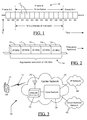
- FIG. 1 illustrates an LTE radio frame 10 (Frame N) in a sequence of radio frames (Frames N-1, N, N+1, etc.) that may constitute the communication "link" between a base station and a mobile handset in a cellular network.
- the radio frame 10 may be of a fixed duration and may be divided into a fixed number of equally-sized subframes 12 identified as subframes "S0" through “S9" in FIG. 1 .
- each radio frame 10 i.e., each of Frame N, Frame N+1, etc.
- the frequency bandwidth of the radio frame 10 may depend on the overall system bandwidth available in the carrier network.
- Each subframe 12 in the radio frame 10 can be allocated as a DL subframe, as a UL subframe, or as a special subframe which consists of the Downlink Pilot Time Slot (DwPTS), Guard Period (GP) and Uplink Pilot Time Slot (UpPTS) fields (not shown).
- DwPTS Downlink Pilot Time Slot
- GP Guard Period
- UpPTS Uplink Pilot Time Slot
- the GP field in the special subframe enables switching between downlink and uplink transmissions in a TDD system.
- Each subframe 12 contains information in the time domain as well as in the frequency domain (involving different sub-carriers).
- a base station may transmit wireless channel resource allocation information to a mobile handset, terminal or User Equipment (UE) via a downlink control signal, such as the Physical Downlink Control Channel (PDCCH) signal in Third Generation Partnership Project (3GPP) 3G and 4G networks.
- a downlink control signal such as the Physical Downlink Control Channel (PDCCH) signal in Third Generation Partnership Project (3GPP) 3G and 4G networks.
- Modern cellular networks e.g., LTE
- HARQ Hybrid Automatic Repeat Request
- the base station can retransmit the erroneous data.
- Such reporting may be performed by the UE using uplink control signaling (i.e., transmission from a mobile device to a base station in a cellular network), which can include one or more of the following: (i) Hybrid-ARQ (HARQ) acknowledgements (ACK/NACK) for received downlink data (from the base station); (ii) terminal reports (e.g., in the form of one or more Channel Quality Indicator (CQI) bits) related to the downlink channel conditions.
- HARQ Hybrid-ARQ
- ACK/NACK Hybrid-ARQ acknowledgements
- CQI Channel Quality Indicator
- Such reports may be used by the base station to assist it in future downlink scheduling of the mobile handset; and (iii) scheduling requests by the UE, indicating that the mobile terminal or UE needs uplink resources for uplink data transmissions.
- a mobile terminal has been assigned an uplink resource for data transmission and, at the same time instance, if the terminal has control information to transmit as well, the terminal will transmit the control information together with the data on PUSCH.
- any control signaling is multiplexed with data to maintain single carrier structure.
- control signaling is on the PUCCH.
- CQI Channel Quality Indicator
- PMI Precoding Matrix Indicator
- RI Rank Indicator
- the CQI, PMI, and RI parameters may constitute Channel Status Information (CSI).
- the CQI/PMI/RI reports (i.e., CSI reports) can be periodic on PUCCH, but can be smaller and often non-frequency-selective. Whereas, CQI/PMI/RI reports can be aperiodic on PUSCH, but may be frequency-selective and larger (wideband or UE-selected sub-band).
- the CSI report (with or without PMI depending on the UE's configured transmission mode) from the UE may be triggered by 1 bit in a PDCCH message from the base station.
- E-UTRA Evolved Universal Terrestrial Radio Access
- TS Technical Specifications
- 36.201 Physical Layer: General Description
- 36.211 Physical Channels and Modulation
- 36.212 Multiplexing and Channel Coding
- 36.213 Physical Layer Procedures
- 36.214 Physical Layer - Measurements
- RRC Radio Resource Control
- LTE Release-8 (Rel-8) now has been standardized to support operating bandwidths of up to 20 MHz.
- 3GPP has initiated work on LTE Release-10 (Rel-10) ("LTE Advanced") to support bandwidths larger than 20 MHz.
- LTE Release-10 (Rel-10)
- One important requirement in LTE Rel-10 is to assure backward compatibility with LTE Rel-8. This includes spectrum compatibility, i.e., an LTE Rel-10 carrier, wider than 20 MHz, should appear as a number of (smaller) LTE carriers to an LTE Rel-8 terminal (i.e., mobile handset or UE). Each such smaller carrier can be referred to as a Component Carrier (CC).
- CC Component Carrier
- CA Carrier Aggregation
- an operating bandwidth of 100 MHz (indicated by reference numeral "14") in Rel-10 may be constructed by the aggregation of five (contiguous, for simplicity) smaller bandwidths of 20 MHz (in compliance with Rel-8 requirements) as indicated by reference numerals "16" through “20". It is noted here that Rel-10 supports aggregation of up to five carriers, each with a bandwidth of up to 20 MHz. Thus, for example, if desired, carrier aggregation in Rel-10 also may be used to aggregate two carriers of 5 MHz bandwidth each.
- the carrier aggregation in uplink and downlink may thus support higher data rates than possible in legacy communication systems (i.e., UE's operating under 3GPP Rel-8, Rel-9, or below).
- UE's capable of operating only over a single Downlink/Uplink (DL/UL) pair may be referred to as “Legacy UE's”
- UE's capable of operating over multiple DL/UL CCs may be referred to as "Advanced-UE's”.
- the number of aggregated CCs as well as the bandwidth of the individual CC may be different for uplink and downlink.
- a "symmetric configuration" refers to the case where the number of CCs in downlink and uplink is the same, whereas an “asymmetric configuration” refers to the case where the number of CCs is different in uplink and downlink.
- the number of CCs configured in the network may be different from the number of CCs "seen" by a terminal (or UE):
- a terminal may, for example, support more downlink CCs than uplink CCs, even though the network offers the same number of uplink and downlink CCs.
- the link between DL CCs and UL CCs can be UE-specific.
- Scheduling of a CC is done on the PDCCH via downlink assignments (from the base station).
- a terminal only operates with one DL and one UL CC. Therefore, the association between DL assignment/UL grant and the corresponding DL and UL CCs is clear in Rel-8.
- cross- 20 carrier scheduling may be enabled where the PDCCH containing DL assignment/UL grant is transmitted on a CC that is different from the CC on which the Physical Downlink Shared Channel (PDSCH) or its associated PUSCH are transmitted.
- PDSCH Physical Downlink Shared Channel
- the carrier aggregation (CA) approach may result in symmetric or asymmetric configurations of component carriers (CCs), and may also support cross-carrier scheduling.
- CCs component carriers
- UCI on PUSCH with CA needs to handle the asymmetric allocation of UL/DL CCs.
- uplink 30 control signaling in a CA environment should be able to handle multiplexing of ACK/NACK and potential CSI feedback for several DL component carriers onto a single UL component carrier.
- current 3GPP standards do not specify how this multiplexing of ACK/NACK and CSI feedback for several DL CCs should be done.
- carrier aggregation it is also possible to have simultaneous transmissions of PUCCH for carrier aggregation (CA PUCCH) and PUSCH in the same subframe. Consequently, not all the UCI need to be mapped either to CA PUCCH or PUSCH. Further, it is also possible that some of the UCI information is transmitted on CA PUCCH on one component carrier while other part of the UCI information is transmitted on PUSCH on another component carrier.
- the different parts of UCI could be, for example, ACK/NACK transmission and CSI, however UCI information can be divided in other ways as well.
- the present invention provides a solution to the above-mentioned need to specify (to the UE) how UCI on PUSCH should be transmitted with carrier aggregation, depending on the carrier on which PUSCH transmission occurs, and is captured in the appended claims. Particular embodiments of the present invention are captured in the dependent claims.
- the teachings of the present invention thus enable a wireless communication network (e.g., a cellular network) to control the mode of operation for a UE's transmission of UCI for different configurations (symmetric or asymmetric) of uplink CCs, for simultaneous transmissions of CA PUCCH and PUSCH in the same subframe, and also for transmissions of parts of UCI on CA PUCCH and PUSCH over different CCs.
- a semi-static UCI mapping bit is used to control which UCI transmission mode must be used by the UE.
- the base station e.g., the eNB
- UCI Uplink Primary Component Carrier
- a hyphenated term e.g., "sub-frame”
- its non-hyphenated version e.g., "subframe”
- a capitalized entry e.g., "Uplink”
- its non-capitalized version e.g., "uplink”
- plural terms may be indicated with or without an apostrophe (e.g., CC's or CCs).
- Coupled means “coupled,” “connected”, “connecting,” “electrically connected,” etc., are used interchangeably herein to generally refer to the condition of being electrically connected.
- a first entity is considered to be in "communication” with a second entity (or entities) when the first entity electrically sends and/or receives (whether through wireline or wireless means) information signals (whether containing voice information or non-voice data/control information) to the second entity regardless of the type (analog or digital) of those signals.
- various figures including component diagrams, graphs, or charts) shown and discussed herein are for illustrative purpose only, and are not drawn to scale.
- FIG. 3 is a diagram of an exemplary wireless system 30 in which UCI transmission control according to the teachings of one embodiment of the present invention may be implemented.
- the system 30 may include a mobile handset 32 that is in wireless communication with a carrier network 34 of a wireless service provider through a communication node 36 of the carrier network 34.
- the communication node 36 may be, for example, an evolved Node-B (eNodeB or eNB) when the carrier network is a Long-Term Evolution (LTE) network, and may provide radio interface to the mobile handset 32.
- the communication node 36 may also include a site controller, an access point (AP), or any other type of radio interface device capable of operating in a wireless environment.
- AP access point
- mobile handset wireless handset
- wireless handset terminal
- user equipment user equipment
- UE user equipment
- Some examples of such mobile handsets include cellular telephones or data transfer equipments (e.g., a Personal Digital Assistant (PDA) or a pager), smartphones (e.g., iPhoneTM, AndroidTM, BlackberryTM, etc.), computers, or any other type of user devices capable of operating in a wireless environment.
- PDA Personal Digital Assistant
- wireless network or “carrier network” may be used interchangeably herein to refer to a wireless communication network (e.g., a cellular network) facilitating voice and/or data communication between two user equipments (UE's).
- the communication node 36 may also perform radio resource management (as, for example, in case of an eNodeB in an LTE system) such as, for example, via Carrier Aggregation (CA) (e.g., aggregation of up to five carriers each having a bandwidth of up to 20 MHz) mentioned hereinbefore.
- Radio resource management as, for example, in case of an eNodeB in an LTE system
- CA Carrier Aggregation
- Communication nodes in other types of carrier networks e.g., 4G networks and beyond
- the node 36 may be configured (in hardware, via software, or both) to implement the UCI transmission control as discussed herein.
- the UCI transmission control methodology may be implemented through suitable programming of one or more processors (e.g., processor 66 (or, more particularly, processing unit 72) in FIG. 6 ) in the communication node 36.
- the execution of the program code may cause the processor to perform UCI transmission control as discussed herein.
- the communication node 36 may be referred to as "performing,” “accomplishing,” or “carrying out” a function or process, it is evident to one skilled in the art that such performance may be technically accomplished in hardware and/or software as desired.
- the UE 32 may be suitably configured (in hardware and/or software) to perform its portion of UCI transmission control as discussed in more detail hereinbelow.
- the carrier network 34 may include a core network 38 coupled to the communication node 36 and providing logical and control functions (e.g., subscriber account management, billing, subscriber mobility management, etc.) in the network 38.
- the core network 38 may be an Access Gateway (AGW).
- AGW Access Gateway
- the core network 38 may function to provide connection of the UE 32 to other mobile handsets operating in the carrier network 34 and also to other communication devices (e.g., wireline phones) or resources (e.g., an Internet website) in other voice and/or data networks external to the carrier network 34.
- the core network 38 may be coupled to a packet-switched network 40 (e.g., an Internet Protocol (IP) network such as the Internet) as well as a circuit-switched network 42 such as the Public-Switched Telephone Network (PSTN) to accomplish the desired connections beyond the devices operating in the carrier network 34.
- IP Internet Protocol
- PSTN Public-Switched Telephone Network
- the carrier network 34 may be a cellular telephone network in which the UE 32 may be a subscriber unit. However, as mentioned before, the present invention is operable in other non-cellular wireless networks as well (whether voice networks, data networks, or both). Furthermore, portions of the carrier network 34 may include, independently or in combination, any of the present or future wireline or wireless communication networks such as, for example, the PSTN, or a satellite-based communication link. Similarly, as also mentioned above, the carrier network 34 may be connected to the Internet via its core network's 38 connection to the IP (packet-switched) network 40 or may include a portion of the Internet as part thereof.
- IP packet-switched
- an LTE Rel-10 terminal may behave similar to an LTE Rel-8 terminal.
- the terminal may - depending on its own capabilities and the network - be configured with additional CCs in the UL and DL.
- This configuration may be based on Radio Resource Control (RRC) signaling on higher layers.
- RRC Radio Resource Control
- a terminal may be initially configured (e.g., by the eNB 36) with multiple CCs even though not all of them are currently used.
- both symmetric and asymmetric uplink/downlink (UL/DL) CC configurations may be supported.
- a terminal may be configured with a number of CCs in both UL and DL.
- the terminal/UE 32 may have to monitor all configured DL CCs for PDCCH and PDSCH. This may require a wider bandwidth, higher sampling rates, etc., which may result in high power consumption at the UE 32.
- LTE Rel-10 also supports a faster mechanism that enables activation/de-activation of CCs (on top of the configuration of CCs mentioned above) by the eNB 36.
- the activated set of CCs will always be a subset of the configured set.
- the purpose behind activation/de-activation-which may be on a faster time scale than configuration- is to have a tool that enables rapid switching of CCs (e.g., by the eNB 36), thereby enabling the terminal (e.g., UE 32) to most of the time only monitor those CCs upon which the network (e.g., the network 34) intends to schedule that terminal.
- the terminal or UE 32 monitors only configured and activated CCs for PDCCH and PDSCH.
- activation may be based on Media Access Control (MAC) control elements, which may be faster than RRC signaling.
- MAC Media Access Control
- the MAC-based activation/de-activation can follow the number of CCs that is required to fulfill the current data rate needs.
- multiple CCs are activated (e.g., by eNB 36), used for data transmission, and de-activated if not needed anymore. All but a single pair of CCs - the DL Primary cell (DL Pcell) and the UL Primary cell (UL Pcell) - can be de-activated.
- Activation therefore provides the possibility to configure multiple CCs but only activate them on as-needed basis.
- a terminal or UE 32 would have one or very few CCs activated, resulting in a lower reception bandwidth and thus reduced battery consumption.
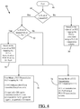
- FIG. 4 is an exemplary flowchart 44 depicting operations related to the two UCI transmission modes according to one embodiment of the present invention.
- the eNB 36 uses radio signaling (e.g., RRC signaling) between the eNB 36 and the UE 32 to control the UE's UCI transmission.
- RRC signaling e.g., RRC signaling
- a mobile handset e.g., the UE 32
- the RRC protocol layer (not shown) exists in the UE 32 and the eNodeB 36, and it is part of the LTE air interface control plane.
- RRC signaling (by the eNB 36) may be used to accomplish many functions such as, for example, broadcast of System Information (SI); establishment, maintenance, and release of an RRC connection between the UE 32 and the eNB 36; establishment, configuration, maintenance, and release of point-to-point Radio Bearer channels between the UE 32 and the eNB 36; and Quality of Service (QoS) management functions.
- the eNB 36 informs the UE 32, through a UCI mapping bit in RRC signaling (which goes from the eNB 36 to the UE 32 via the RRC protocol), which of the below-described two UCI mapping modes of operation (i.e., UCI transmission modes) to use to transmit UCI to the eNB 36.
- the eNB 36 may implicitly provide the UCI mapping bit through the value of the RRC signaling parameter "simultaneous PUCCH-PUSCH" (defined in LTE Rel-10), which has the values of "true” or “false.” If this parameter is not present in the RRC message, it has the value of "false", else it has the value of "true.” Thus, for example, the UCI mapping bit is "1” or “true” if the RRC parameter "simultaneous PUCCH-PUSCH” is "true”, and the UCI mapping bit is "0” or "false” if the RRC parameter "simultaneous PUCCH-PUSCH” is "false.”
- the eNB 36 can control the UE's transmission of UCI in accordance with the value of the UCI mapping bit. In other words, the value of the UCI mapping
- the UCI mapping bit is provided by eNB 36 (to the UE 32) when CA is present.
- references to a Component Carrier (CC) or a Primary cell (Pcell) "associated with" the UE 32 relate to a CC or CCs that are configured and activated (e.g., by the eNB 36) for the UE 32-i.e., CC or CCs on which the UE is scheduled to transmit.
- the term "UCI" may include one or more of the following: ACK/NACK feedback information, CQI, PMI, and RI.
- the CQI, PMI, and RI parameters may constitute CSI (Channel Status Information).
- CSI reports from the UE may be reported periodically (periodic CSI) or triggered aperiodically (aperiodic CSI).
- periodic CSI is the CSI that is configured to be reported periodically, wherein the periodicity is configured by the eNB for the UE.
- aperiodic CSI is the CSI that is triggered by the eNB for the UE through the setting of a bit in the UL scheduling grant message (e.g., the Downlink Control Information (DCI) message).
- DCI Downlink Control Information
- the UE 32 may be required (or configured (e.g., in hardware and/or software as mentioned earlier)) to follow the first pre-determined mode of UCI transmission when the received UCI mapping bit (from the eNB 36) has a first distinct value.
- This first value may be a "0", or "off”, or any other logical value (binary or non-binary) that is different from the second value discussed below with reference to the second pre-determined mode of UCI transmission.
- the first mode of UCI transmission (after the "Start" block 46 in FIG.
- the UE 32 may transmit UCI as follows, depending on whether a PUSCH is to be transmitted (by the UE 32) in the current subframe (e.g., a subframe 12 in an LTE radio frame 10 discussed earlier with reference to FIG. 1 ).
- the term "current subframe” herein refers to a UL subframe that is currently being transmitted from the UE 32 to the eNB 36.
- the UE 32 may be required (or configured (e.g., in hardware and/or software as mentioned earlier)) to follow the second mode of UCI transmission when the received UCI mapping bit (from the eNB 36) has a second distinct value.
- This second value may be a "1", or “on”, or any other logical value (binary or non-binary) that is different from the first value discussed above with reference to the first mode of UCI transmission.
- the UE 32 may transmit UCI as follows, again depending on whether a PUSCH is to be transmitted (by the UE 32) in the current subframe.
- both mode differ when there is PUSCH transmission on a UL CC, but not on the UL Pcell.
- UCI is either transmitted on PUSCH on a given component carrier according to a rule (under first mode of UCI transmission), or UCI is forced to be transmitted on PUCCH on the UL Pcell (under second mode of UCI transmission).
- the eNB 36 may monitor reception quality of a signal (e.g., a Reference Signal (RS) on PUSCH, or a PUSCH, or a Sounding Reference Signal (SRS)) transmitted on a UL CC (including UL Pcell) associated with the UE 32, and may determine the value of the UCI mapping bit based on the reception quality of this signal.
- a signal e.g., a Reference Signal (RS) on PUSCH, or a PUSCH, or a Sounding Reference Signal (SRS)
- a UL CC including UL Pcell
- the eNB 36 may set the value of the UCI mapping bit equal to "1" (or any other value that triggers the second mode of UCI transmission) when the reception quality on the UL CC according to the first mode of UCI transmission (under any of the sub-paragraphs (I-A), (I-B), or (I-C) above) is not above an eNB implementation-specific threshold.
- eNB 36 may initially set the value of the UCI mapping bit, or re-configure the value of the UCI mapping bit and switch from the first mode to the second mode of UCI transmission, based on the quality of signaling on the UL CCs associated with the UE 32.
- the eNB 36 may determine the value of the UCI mapping bit based on a comparison of available bandwidths of all UL CCs associated with the UE 32. Such comparison allows the network (e.g., through the eNB 36 in the carrier network 34) to either configure an exemplary rule when a UL CC with wide bandwidth is available (as discussed under sub-paragraph (I-C)(a) in case of the first mode of UCI transmission) or to enforce the UCI transmission on the UL Pcell (as under sub-paragraph (II-C) in case of the second mode of UCI transmission).
- the network 34 may control UE's 32 transmission of UCI as desired.
- the UCI mapping bit-based UCI transmission control discussed above may be applicable to cases where part of the UCI is configured (e.g., by the UE 32 with/without instructions from the eNB 36) to be transmitted on PUCCH (e.g., a CA PUCCH under LTE Rel-10) and another part of the UCI is configured to be transmitted on PUSCH in the same subframe as mentioned under the "Summary" section earlier.
- PUCCH e.g., a CA PUCCH under LTE Rel-10
- the different parts of UCI could be, for example, ACK/NACK transmission and CSI, however UCI information can be divided in other ways as well.
- Such simultaneous transmission of CA PUCCH on one component carrier and PUSCH on another component carrier in the same subframe may be possible, for example, in the first mode of UCI transmission as discussed under sub-paragraph (I-C) above or in the second mode of UCI transmission as discussed under sub-paragraph (II-C) above.
- such simultaneous transmission of CA PUCCH on one component carrier and PUSCH on another component carrier in the same subframe may be possible using the second mode of UCI transmission as discussed under sub-paragraph (I-B) above and the second mode of UCI transmission as discussed under sub-paragraph (II-B) above.
- FIG. 5 is a block diagram of an exemplary mobile handset or UE 32 according to one embodiment of the present invention.
- the UE 32 may include a transceiver 60, an antenna 61, a processor 63, and a memory 64.
- some or all of the functionalities described above e.g., reception of UCI mapping bit from the eNB 36 via the antenna 61 and transceiver 60; storage of the value of the UCI mapping bit in the memory 64; selection of one of the two modes of UCI transmission as per the value of the UCI mapping bit; transmission of UCI to eNB 36 as per the selected UCI transmission mode via transceiver 60 and antenna 61; etc.
- the UE processor 63 executing instructions stored on a computer-readable medium, such as the memory 64 shown in FIG.
- Alternative embodiments of the UE 32 may include additional components beyond those shown in FIG. 5 that may be responsible for providing certain aspects of the UE's functionality, including any of the functionality described above and/or any functionality necessary to support the solution described above (e.g., operations shown and discussed with reference to the flowchart 44 in FIG. 4 ).
- FIG. 6 is a block diagram of an exemplary eNodeB (or a similar communication node) 36 according to one embodiment of the present invention.
- the eNodeB 36 may include a baseband processor 66 to provide radio interface with the mobile handsets (in the carrier network 34) via eNodeB's Radio Frequency (RF) transmitter 68 and RF receiver 70 units coupled to the eNodeB antenna 39.
- the processor 66 may be configured (in hardware and/or software) to determine a value of a UCI mapping bit and to supply the UCI mapping bit to the UE 32 via appropriate downlink signals (e.g., RRC signaling) to control UE's 32 transmission of UCI as per the teachings of the present invention.
- the processor 66 may also supply any specific rule of UCI transmission under the first mode of UCI transmission discussed hereinbefore or may specify any specific PUCCH transmission scheme for the UE 32 to use during UCI transmission under either of the above-described two modes.
- the transmissions from the UE 32 may be received at the receiver 70, whereas eNB's transmissions to the UE 32 may be carried out via the transmitter 68.
- the baseband processor 66 may include a processing unit 72 in communication with a memory 74 to provide, for example, a UCI mapping bit to the UE 32 as per the teachings of the present invention.
- a scheduler (e.g., the scheduler 76 in FIG.
- the scheduler 76 may have the same data structure as a typical scheduler in an eNB in an LTE system.
- the processor 66 may also provide additional baseband signal processing (e.g., mobile device registration, channel signal information transmission, radio resource management, etc.) as required.
- the processing unit 72 may include, by way of example, a general purpose processor, a special purpose processor, a conventional processor, a digital signal processor (DSP), a plurality of microprocessors, one or more microprocessors in association with a DSP core, a controller, a microcontroller, Application Specific Integrated Circuits (ASICs), Field Programmable Gate Arrays (FPGAs) circuits, any other type of integrated circuit (IC), and/or a state machine.
- DSP digital signal processor
- ASICs Application Specific Integrated Circuits
- FPGAs Field Programmable Gate Arrays
- a mobile base station a base station controller, a node B, an enhanced node B, a pico/femto base station, and/or any other type of mobile communications node
- the processing unit 72 executing instructions stored on a computer-readable data storage medium, such as the memory 74 shown in FIG. 6 .
- the eNodeB 36 may further include a timing and control unit 78 and a core network interface unit 80 as illustrated in FIG. 6 .
- the control unit 78 may monitor operations of the processor 66 and the network interface unit 80, and may provide appropriate timing and control signals to these units.
- the interface unit 80 may provide a bi-directional interface for the eNodeB 36 to communicate with the core network 38 to facilitate administrative and call-management functions for mobile subscribers operating in the carrier network 34 through eNodeB 36.
- Alternative embodiments of the base station 36 may include additional components responsible for providing additional functionality, including any of the functionality identified above and/or any functionality necessary to support the solution described above (e.g., operations shown and discussed with reference to the flowchart 44 in FIG. 4 ).
- additional components responsible for providing additional functionality, including any of the functionality identified above and/or any functionality necessary to support the solution described above (e.g., operations shown and discussed with reference to the flowchart 44 in FIG. 4 ).
- features and elements are described above in particular combinations, each feature or element can be used alone without the other features and elements or in various combinations with or without other features and elements.
- the methodology provided herein (related to the supply of a UCI mapping bit to a UE 32 and control of UE's UCI transmission in accordance with the value of the UCI mapping bit) may be implemented in a computer program, software, or firmware incorporated in a computer-readable storage medium (e.g., the memory 64 in FIG. 5 and memory 74 in FIG.
- Examples of computer-readable storage media include a Read Only Memory (ROM), a Random Access Memory (RAM), a digital register, a cache memory, semiconductor memory devices or structures, magnetic media such as internal hard disks, magnetic tapes and removable disks, magneto-optical media, and optical media such as CD-ROM disks and Digital Versatile Disks (DVDs).
- ROM Read Only Memory
- RAM Random Access Memory
- DRAM Digital Versatile Disks
- a semi-static signaling of a UCI mapping bit (via RRC parameter known as "simultaneous PUCCH-PUSCH") is used by a base station to require the UE to transmit UCI using one of two pre-determined UCI transmission modes.
- the value of the bit can be decided by the base station (e.g., eNB), considering, for example, the available bandwidth or quality of different UL CCs associated with the UE.
- a wireless communication network e.g., a cellular network
- This network-based solution allows the network to either configure a general rule of UCI transmission by the UE or to enforce the UCI transmission on the Uplink Primary Component Carrier (UL PCC or UL Pcell).
- UL PCC Uplink Primary Component Carrier
Landscapes
- Engineering & Computer Science (AREA)
- Signal Processing (AREA)
- Computer Networks & Wireless Communication (AREA)
- Quality & Reliability (AREA)
- Mobile Radio Communication Systems (AREA)
Claims (26)
- Verfahren zum Steuern einer Übertragung von Uplink Control Information (Aufwärtssteuerinformationen), UCI, durch eine Anwendervorrichtung, UE, (32), die konfiguriert ist, mit einem Prozessor (36) über ein mit diesem verknüpftes drahtloses Netzwerk (34) in Funkkommunikation zu sein, wobei das Verfahren die Schritte umfasst:Bereitstellen einer Funksignalisierung an die UE (32) unter Verwendung des Prozessors (66);Zuleiten eines UCI-Zuweisungs-Bits zur UE (32) durch die Funksignalisierung unter Verwendung des Prozessors (66), um somit die Übertragung durch die UE der UCI gemäß einem Wert des UCI-Zuweisungs-Bits zu steuern,wobei das Zuleiten eines UCI-Zuweisungs-Bits eines der folgenden enthält:Zuleiten eines ersten Werts für das UCI-Zuweisungs-Bit unter Verwendung des Prozessors (66) zum Anweisen der UE, einen ersten UCI-Übertragungsmodus auszuführen; undZuleiten eines zweiten Werts für das UCI-Zuweisungs-Bit unter Verwendung des Prozessors (66) zum Anweisen der UE, einen zweiten UCI-Übertragungsmodus auszuführen, wobei sich der zweite Wert vom ersten Wert unterscheidet, dadurch gekennzeichnet, dass sich der erste UCI-Übertragungsmodus und der zweite UCI-Übertragungsmodus unterscheiden, wenn eine Physical Uplink Shared Channel (gemeinsamer physischer Aufwärtskanal), PUSCH, Übertragung auf einem Uplink Component Carrier (Aufwärtskomponententräger), UL CC, aber nicht auf einer UL Primary Cell (UL-Primärzelle) vorliegt.
- Verfahren nach Anspruch 1, wobei die Funksignalisierung eine Radio Resource Control (Steuerung funktechnischer Ressourcen), RRC, Signalisierung ist.
- Verfahren nach Anspruch 2, wobei das UCI-Zuweisungs-Bit der UE (32) durch einen RRC Signalisierungsparameter zugeleitet wird, der als "simultaner Physical Uplink Control Channel (physischer Aufwärtssteuerkanal), PUCCH - Physical Uplink Shared Channel, PUSCH" bezeichnet wird.
- Verfahren nach Anspruch 1, wobei das UCI-Zuweisungs-Bit mit Carrier Aggregation (Trägeraggregation), CA, verwendet wird und wobei eines der folgenden gilt:bei Fehlen einer Übertragung eines Physical Uplink Shared Channel, PUSCH, von der UE (32) in einem aktuellen Teilrahmen auf einem Uplink Component Carrier, UL CC, der mit der UE (32) verknüpft ist, weist der Wert des UCI-Zuweisungs-Bits die UE (32) an, die UCI im aktuellen Teilrahmen unter Verwendung eines ersten Physical Uplink Control Channel, PUCCH, Übertragungsschemas zu übertragen, wobei der Wert des UCI-Zuweisungs-Bits entweder ein erster Wert oder ein zweiter Wert ist, der sich vom ersten Wert unterscheidet;im Fall einer Übertragung des PUSCH von der UE (32) auf einer Uplink Primary Cell (Aufwärtsprimärzelle), UL Pcell, im aktuellen Teilrahmen weist der Wert des UCI-Zuweisungs-Bits die UE (32) an, die UCI im aktuellen Teilrahmen unter Verwendung des PUSCH zu übertragen, wobei der Wert des UCI-Zuweisungs-Bits entweder der erste Wert oder der zweite Wert ist;wenn der Wert des UCI-Zuweisungs-Bits der erste Wert ist und im Fall einer Übertragung des PUSCH von der UE (32) im aktuellen Teilrahmen auf einem UL CC, der mit der UE (32) verknüpft ist, mit Ausnahme der UL Pcell, gilt folgendes:der erste Wert des UCI-Zuweisungs-Bits weist die UE (32) an, die UCI ausschließlich aperiodischer Channel Status Information (Kanalstatusinformationen), CSI, die darin enthalten sind, im aktuellen Teilrahmen unter Verwendung des PUSCH basierend auf einer vorgegebenen Regel zu übertragen, undder erste Wert des UCI-Zuweisungs-Bits weist die UE an, die UCI, die zumindest die aperiodischen CSI enthalten, auf einem entsprechenden UL CC im aktuellen Teilrahmen unter Verwendung des PUSCH zu übertragen, wobei der entsprechende UL CC einem Downlink Componenten Carrier (Abwärtskomponententräger), DL CC entspricht, der eine Meldung aperiodischer CSI auslöst; undwenn der Wert des UCI-Zuweisungs-Bits der zweite Wert ist und im Fall einer Übertragung des PUSCH von der UE im aktuellen Teilrahmen auf einem UL CC, der mit der UE verknüpft ist, mit Ausnahme der UL Pcell, weist der zweite Wert des UCI-Zuweisungs-Bits die UE (32) an, die UCI im aktuellen Teilrahmen unter Verwendung eines zweiten PUCCH Übertragungsschemas zu übertragen.
- Verfahren nach Anspruch 4, wobei die vorgegebene Regel erfordert, dass die UE (32) die UCI ausschließlich der aperiodischen CSI im aktuellen Teilrahmen unter Verwendung des PUSCH auf einem UL CC überträgt, der mit der UE (32) verknüpft ist und die breiteste Bandbreite unter allen UL CCs hat, die mit der UE (32) verknüpft sind.
- Verfahren nach Anspruch 4, wobei jedes von dem ersten und dem zweiten PUCCH Übertragungsschema eines der folgenden ist:ein PUCCH Übertragungsschema für CA;ein PUCCH Übertragungsschema für Long Term Evolution, LTE, Release-8; undein PUCCH Übertragungsschema für LTE Release-9,wobei das PUCCH Übertragungsschema für CA eines der folgenden enthält:ein PUCCH Übertragungsschema basierend auf PUCCH Format 3; undein PUCCH Übertragungsschema basierend auf PUCCH Format 1b mit Kanalauswahl; undwobei jedes von dem PUCCH Übertragungsschema für LTE Release-8 und dem PUCCH Übertragungsschema für LTE Release-9 eines der folgenden enthält:ein PUCCH Übertragungsschema basierend auf PUCCH Format 1a;ein PUCCH Übertragungsschema basierend auf PUCCH Format 1b;ein PUCCH Übertragungsschema basierend auf PUCCH Format 2;ein PUCCH Übertragungsschema basierend auf PUCCH Format 2a; undein PUCCH Übertragungsschema basierend auf PUCCH Format 2b.
- Verfahren nach Anspruch 4, wobei eines der folgenden gilt:bei Fehlen einer Übertragung des PUSCH, von der UE (32) im aktuellen Teilrahmen auf einem UL CC, der mit der UE (32) verknüpft ist, weist der Wert des UCI-Zuweisungs-Bits die UE an, die UCI auf der UL Pcell für die UE (32) im aktuellen Teilrahmen unter Verwendung des ersten PUCCH Übertragungsschemas zu übertragen;im Fall einer Übertragung des PUSCH von der UE (32) auf der UL Pcell im aktuellen Teilrahmen, weist der Wert des UCI-Zuweisungs-Bits die UE (32) an, die UCI auf der UL Pcell im aktuellen Teilrahmen unter Verwendung des PUSCH zu übertragen;wenn der Wert des UCI-Zuweisungs-Bits der erste Wert ist und im Fall einer Übertragung des PUSCH von der UE (32) im aktuellen Teilrahmen auf einem UL CC, der mit der UE verknüpft ist, mit Ausnahme der UL Pcell, weist der erste Wert des UCI-Zuweisungs-Bits die UE (32) an, die UCI, die zumindest die aperiodischen CSI enthalten, auf einem entsprechenden UL CC im aktuellen Teilrahmen unter Verwendung des PUSCH zu übertragen, wobei der entsprechende UL CC mit der UE verknüpft ist und einem Downlink Component Carrier, DL CC, entspricht, der eine Meldung der aperiodischen CSI an den Prozessor auslöst; undwenn der Wert des UCI-Zuweisungs-Bits der zweite Wert ist und im Fall einer Übertragung des PUSCH von der UE im aktuellen Teilrahmen auf einem UL CC, der mit der UE, verknüpft ist, mit Ausnahme der UL Pcell, weist der zweite Wert des UCI-Zuweisungs-Bits die UE an, die UCI auf der UL Pcell für die UE im aktuellen Teilrahmen unter Verwendung des zweiten PUCCH Übertragungsschemas zu übertragen.
- Verfahren nach Anspruch 1, wobei die UCI zumindest eines der folgenden enthalten:Bestätigung/Negativbestätigung, ACK/NACK, Feedbackinformationen;einen Channel Quality Indicator (Kanalqualitätsindikator), CQI;einen Precoding Matrix Indicator (Präcodierungsmatrixindikator), PMI; undeinen Rank Indicator (Rangindikator), RI.
- Verfahren nach Anspruch 1, wobei das UCI-Zuweisungs-Bit mit Carrier Aggregation, CA, verwendet wird und wobei das Verfahren des Weiteren durch die Schritte gekennzeichnet ist:Überwachen der Empfangsqualität eines Signals, das auf einem Uplink Component Carrier, UL CC, der mit der UE (32) verknüpft ist, übertragen wird, unter Verwendung des Prozessors (66); undErmitteln des Werts des UCI-Zuweisungs-Bits, basierend auf der Empfangsqualität des Signals, unter Verwendung des Prozessors (66).
- Verfahren nach Anspruch 1, wobei das UCI-Zuweisungs-Bit mit Carrier Aggregation, CA, verwendet wird und wobei das Verfahren des Weiteren durch den Schritt gekennzeichnet ist:Ermitteln des Werts des UCI-Zuweisungs-Bits, basierend auf der Empfangsqualität des Signals, basierend auf einem Vergleich verfügbarer Bandbreiten aller Uplink Component Carriers, UL CCs, die mit der UE (32) verknüpft sind, unter Verwendung des Prozessors (66).
- Verfahren zum Steuern einer Übertragung von Uplink Control Information (Aufwärtssteuerinformationen), UCI, umfassend die Schritte:Verwenden eines Mobiltelefons (32), das ein Uplink Control Information, UCI, Zuweisungs-Bit durch Funksignalisierung von einem Mobilkommunikationsknoten (36) empfängt, der durch ein mit diesem verknüpftes Funknetzwerk (34) in Funkverbindung mit dem Mobiltelefon steht;Übertragen der UCI zum Mobilkommunikationsknoten gemäß einem Wert des UCI-Zuweisungs-Bits unter Verwendung des Mobiltelefons (32),wobei das UCI-Zuweisungs-Bit mit Carrier Aggregation (Trägeraggregation), CA, verwendet wird und wobei das Übertragen der UCI eines der folgenden enthält:Übertragen der UCI unter Verwendung eines ersten vorgegebenen UCI Übertragungsmodus, wenn der Wert des UCI-Zuweisungs-Bits ein erster Wert ist; undÜbertragen der UCI unter Verwendung eines zweiten vorgegebenen UCI Übertragungsmodus, wenn der Wert des UCI-Zuweisungs-Bits ein zweiter Wert ist; wobei sich der zweite Wert vom ersten Wert unterscheidet, dadurch gekennzeichnet, dasssich der erste UCI-Übertragungsmodus und der zweite UCI-Übertragungsmodus unterscheiden, wenn eine Physical Uplink Shared Channel, PUSCH, Übertragung auf einem Uplink Component Carrier, UL CC, aber nicht auf einer UL Primary Cell vorliegt.
- Verfahren nach Anspruch 11, wobei ein Übertragen der UCI unter Verwendung des ersten vorgegebenen UCI-Übertragungsmodus eines der folgenden enthält:bei Fehlen einer Übertragung eines Physical Uplink Shared Channel, PUSCH, vom Mobiltelefon in einem aktuellen Teilrahmen auf einem Uplink Component Carrier, UL CC, der mit dem Mobiltelefon verknüpft ist, Übertragen der UCI auf einer Uplink Primary Cell, UL Pcell, für das Mobiltelefon im aktuellen Teilrahmen unter Verwendung eines Physical Uplink Control Channel, PUCCH;im Fall einer Übertragung des PUSCH vom Mobiltelefon auf der UL Pcell im aktuellen Teilrahmen Übertragen der UCI im aktuellen Teilrahmen unter Verwendung des PUSCH; undim Fall einer Übertragung des PUSCH vom Mobiltelefon im aktuellen Teilrahmen auf einem UL CC, der mit dem Mobiltelefon verknüpft ist, mit Ausnahme der UL Pcell, gilt folgendes:Übertragen der UCI ausschließlich aperiodischer Channel Status Information, CSI, die darin enthalten sind, im aktuellen Teilrahmen unter Verwendung des PUSCH basierend auf einer vorgegebenen Regel undÜbertragen der UCI, die die aperiodischen CSI enthalten, auf einem entsprechenden UL CC im aktuellen Teilrahmen unter Verwendung des PUSCH, wobei der entsprechende UL CC mit dem Mobiltelefon verknüpft ist und einem Downlink Componenten Carrier, DL CC, entspricht, der eine Meldung der aperiodischen CSI an den Mobilkommunikationsknoten auslöst.
- Verfahren nach Anspruch 12, wobei das Übertragen der UCI basierend auf der vorgegebenen Regel enthält:Übertragen der UCI ausschließlich aperiodischer Channel Status Information, CSI, im aktuellen Teilfahmen unter Verwendung des PUSCH auf einem UL CC, der mit dem Mobiltelefon verknüpft ist und die breiteste Bandbreite unter allen UL CCs hat, die mit dem Mobiltelefon verknüpft sind.
- Verfahren nach Anspruch 11, wobei das Übertragen der UCI unter Verwendung des zweiten vorgegebenen Modus einer UCI Übertragung eines der folgenden enthält:bei Fehlen einer Übertragung eines Physical Uplink Shared Channel, PUSCH, vom Mobiltelefon in einem aktuellen Teilrahmen auf einem Uplink Component Carrier, UL CC, der mit dem Mobiltelefon verknüpft ist, Übertragen der UCI auf einer Uplink Primary Cell, UL Pcell, für das Mobiltelefon im aktuellen Teilrahmen unter Verwendung eines ersten Physical Uplink Control Channel, PUCCH, Übertragungsschemas;im Fall einer Übertragung des PUSCH vom Mobiltelefon auf dem UL CC im aktuellen Teilrahmen, Übertragen der UCI auf der UL Pcell im aktuellen Teilrahmen unter Verwendung des PUSCH; undim Fall einer Übertragung des PUSCH vom Mobiltelefon im aktuellen Teilrahmen auf einem UL CC, der mit dem Mobiltelefon verknüpft ist, mit Ausnahme der UL Pcell, Übertragen der UCI auf der UL Pcell für das Mobiltelefon im aktuellen Teilrahmen unter Verwendung eines zweiten PUCCH Übertragungsschemas.
- Verfahren nach Anspruch 14, wobei jedes von dem ersten und dem zweiten PUCCH Übertragungsschema eines der folgenden ist:ein PUCCH Übertragungsschema für CA;ein PUCCH Übertragungsschema für Long Term Evolution, LTE, Release-8; undein PUCCH Übertragungsschema für LTE Release-9.
- Verfahren nach Anspruch 11, wobei UCI zumindest eines der folgenden enthalten:Bestätigung/Negativbestätigung, ACK/NACK, Feedbackinformationen;einen Channel Quality Indicator, CQI;einen Precoding Matrix Indicator, PMI; und einen Rank Indicator, RI.
- Mobilkommunikationsknoten (36), der zum Steuern einer Übertragung von Uplink Control Information, UCI, durch eine Anwendervorrichtung, UE, (32) gestaltet ist, die mit einem Mobilkommunikationsknoten durch ein Funknetzwerk (34), das mit der UE (32) verknüpft ist, in Funkkommunikation steht, wobei der Mobilfunkknoten (36) konfiguriert ist, folgendes auszuführen:Bereitstellen einer Radio Resource Control, RRC, Signalisierung für die UE;Ermitteln eines Wertes eines UCI-Zuweisungs-Bits;Senden des UCI-Zuweisungs-Bits zur UE durch die RRC Signalisierung, um somit die Übertragung durch die UE der UCI gemäß dem Wert des UCI-Zuweisungs-Bits zu steuern, wobei das UCI-Zuweisungs-Bit mit Carrier Aggregation, CA, verwendet wird, undwobei der Mobilkommunikationsknoten ferner konfiguriert ist, eines der folgenden als Teil eines Sendens des UCI-Zuweisungs-Bits zur UE auszuführen:Senden eines ersten Werts für das UCI-Zuweisungs-Bit zum Anweisen der UE, einen ersten vorgegebenen UCI-Übertragungsmodus auszuführen; undSenden eines zweiten Werts für das UCI-Zuweisungs-Bit zum Anweisen der UE, einen zweiten vorgegebenen UCI-Übertragungsmodus auszuführen, wobei sich der zweite Wert vom ersten Wert unterscheidet, dadurch gekennzeichnet, dasssich der erste UCI-Übertragungsmodus und der zweite UCI-Übertragungsmodus unterscheiden, wenn eine Physical Uplink Shared Channel, PUSCH, Übertragung auf einem Uplink Component Carrier, UL CC, aber nicht auf einer UL Primary Cell vorliegt.
- Mobilkommunikationsknoten (36) nach Anspruch 17, wobei der Mobilkommunikationsknoten (36) zum Ermitteln des Werts des UCI-Zuweisungs-Bits unter Verwendung eines RRC Signalisierungsparameters konfiguriert ist, der als "simultaner Physical Uplink Control Channel, PUCCH - Physical Uplink Shared Channel, PUSCH" bezeichnet wird.
- Mobilkommunikationsknoten (36) nach Anspruch 17, wobei das das UCI-Zuweisungs-Bit mit Carrier Aggregation, CA, verwendet wird und wobei der Mobilkommunikationsknoten (36) ferner zum Durchführen eines der folgenden als Teil der Ermittlung des Werts des UCI-Zuweisungs-Bits konfiguriert ist:Ermitteln des Werts des UCI-Zuweisungs-Bits basierend auf einer Empfangsqualität eines Signals, das auf einem Uplink Component Carrier, UL CC, der mit der UE (32) verknüpft ist, übertragen und am Mobilkommunikationsknoten (36) empfangen wird; undErmitteln des Werts des UCI-Zuweisungs-Bits basierend auf einem Vergleich verfügbarer Bandbreiten aller Uplink Component Carriers, UL CCs, die mit der UE (32) verknüpft sind.
- Mobilkommunikationsknoten (36) nach Anspruch 17, der des Weiteren konfiguriert ist, eines der folgenden durchzuführen:Empfangen zumindest eines der folgenden von der UE (32) als Teil des ersten vorgegebenen Modus einer UCI Übertragung:UCI, die unter Verwendung des Physical Uplink Control Channel, PUCCH, auf einer Uplink Primärzelle, UL PCell, für die UE (32) übertragen werden:UCI, die auf der UL Pcell unter Verwendung eines Physical Uplink Control Channel, PUSCH, übertragen werden;UCI, ausschließlich aperiodischer Channel Status Information, CSI, die darin enthalten sind, die unter Verwendung des PUSCH basierend auf einer vorgegebenen Regel übertragen werden; undUCI, die die aperiodischen CSI enthalten, die auf einem Uplink Component Carrier, UL CC übertragen werden, der mit der UE verknüpft ist und einem Downlink Component Carrier, DL CC, entspricht, der eine Meldung der aperiodischen CSI an den Mobilkommunikationsknoten auslöst.
- Mobilkommunikationsknoten (36) nach Anspruch 17, der des Weiteren konfiguriert ist, eines der folgenden durchzuführen:Empfangen zumindest eines der folgenden von der UE (32) als Teil des zweiten vorgegebenen Modus einer UCI Übertragung:UCI, die unter Verwendung eines ersten Physical Uplink Control Channel, PUCCH, Übertragungsschemas auf einer Uplink Primary Cell, UL Pcell, für die UE übertragen werden;UCI, die auf der UL Pcell unter Verwendung eines Physical Uplink Shared Channel, PUSCH, übertragen werden; undUCI, die unter Verwendung eines zweiten PUCCH, Übertragungsschemas auf der UL Pcell für die UE übertragen werden.
- Anwendervorrichtung, UE, (32), die zum Durchführen von Folgendem konfiguriert ist:Empfangen eines Uplink Control Information, UCI, Zuweisungs-Bits über Radio Resource Control, RRC, Signalisierung von einem Mobilkommunikationsknoten (36), der durch ein damit verknüpftes Funknetzwerk (34) in Funkkommunikation mit der UE steht;Übertragen der UCI zum Mobilkommunikationsknoten (36) gemäß einem Wert des UCI-Zuweisungs-Bits,wobei das das UCI-Zuweisungs-Bit mit Carrier Aggregation, CA, verwendet wird und wobei die UE (32) ferner konfiguriert ist, eines der folgenden als Teil einer Übertragung der UCI zum Mobilkommunikationsknoten (36) auszuführen:Übertragen der UCI unter Verwendung eines ersten vorgegebenen UCI Übertragungsmodus, wenn der Wert des UCI-Zuweisungs-Bits ein erster Wert ist; undÜbertragen der UCI unter Verwendung eines zweiten vorgegebenen UCI Übertragungsmodus, wenn der Wert des UCI-Zuweisungs-Bits ein zweiter Wert ist, wobei sich der zweite Wert vom ersten Wert unterscheidet, dadurch gekennzeichnet, dasssich der erste UCI-Übertragungsmodus und der zweite UCI-Übertragungsmodus unterscheiden, wenn eine Physical Uplink Shared Channel, PUSCH, Übertragung auf einem Uplink Component Carrier, UL CC, aber nicht auf einer UL Primary Cell vorliegt.
- UE (32) nach Anspruch 22, wobei die UE (32) des Weiteren zum Durchführen zumindest eines der folgenden als Teil der Übertragung der UCI unter Verwendung des ersten vorgegebenen UCI Übertragungsmodus konfiguriert ist:Übertragen der UCI unter Verwendung des Physical Uplink Control Channel, PUCH, auf einer Uplink Primary Cell, UL Pcell, für die UE (32);Übertragen der UCI auf der UL Pcell unter Verwendung eines Physical Uplink Shared Channel, PUSCH;Übertragen der UCI ausschließlich aperiodischer Channel Status Information, CSI, die darin enthalten sind, unter Verwendung des PUSCH basierend auf einer vorgegebenen Regel; undÜbertragen der UCI, die die aperiodischen CSI enthalten, auf einem Uplink Component Carrier, UL CC, der mit der UE (32) verknüpft ist und einem entsprechenden Downlink Componenten Carrier, DL CC, der eine Meldung der aperiodischen CSI an den Mobilkommunikationsknoten auslöst.
- UE (32) nach Anspruch 23, wobei die vorgegebene Regel erfordert, dass die UE (32) die UCI ausschließlich der aperiodischen CSI unter Verwendung des PUSCH auf einem UL CC überträgt, der mit der UE (32) verknüpft ist und die breiteste Bandbreite unter allen UL CCs hat, die mit der UE verknüpft sind.
- UE (32) nach Anspruch 22, wobei die UE (32) ferner zum Durchführen zumindest eines der folgenden als Teil einer Übertragung der UCI unter Verwendung des zweiten vorgegebenen UCI-Übertragungsmodus konfiguriert ist:Übertragen der UCI unter Verwendung eines ersten Physical Uplink Control Channel, PUCCH, Übertragungsschemas auf einer Uplink Primary Cell, UL Pcell, für die UE (32);Übertragen der UCI auf der UL Pcell unter Verwendung eines Physical Uplink Shared Channel, PUSCH; undÜbertragen der UCI unter Verwendung eines zweiten PUCCH-Übertragungsschemas auf der UL Pcell für die UE.
- Mobilkommunikationssystem (30), umfassend:ein Mobiltelefon (32), das zum Operieren in einem verknüpften Funknetzwerk (34) konfiguriert ist; undeinen Mobilkommunikationsknoten (36), der zum Bereitstellen einer Funkschnittstelle für das Mobiltelefon (32) im Funknetzwerk konfiguriert ist, wobei der Mobilkommunikationsknoten (36) ferner konfiguriert ist, folgendes durchzuführen:Bereitstellen einer Radio Resource Control, RRC, Signalisierung für das Mobiltelefon (32);Ermitteln von zwei Werten für ein Uplink Control Information, UCI, Zuweisungs-Bit,Senden eines der folgenden über die RRC-Signalisierung zum Mobiltelefon (32), um somit die Übertragung der UCI durch das Mobiltelefon (32) zu steuern:des UCI-Zuweisungs-Bits mit einem ersten Wert von den zwei Werten, wodurch das Mobiltelefon (32) angewiesen wird, einen ersten UCI Übertragungsmodus durchzuführen, unddes UCI-Zuweisungs-Bits mit einem zweiten Wert von den zwei Werten, wodurch das Mobiltelefon (32) angewiesen wird, einen zweiten UCI Übertragungsmodus durchzuführen,wobei das Mobiltelefon (32) des Weiteren zum Durchführen der folgenden konfiguriert ist:Empfangen des UCI-Zuweisungs-Bits vom Mobilkommunikationsknoten durch RRC Signalisierung,Übertragen der UCI unter Verwendung des ersten UCI Übertragungsmodus, wenn das UCI-Zuweisungs-Bit mit dem ersten Wert empfangen wird, undÜbertragen der UCI unter Verwendung des zweiten UCI Übertragungsmodus, wenn das UCI-Zuweisungs-Bit mit dem zweiten Wert empfangen wird,dadurch gekennzeichnet, dassbei einer Übertragung eines Physical Uplink Shared Channel, PUSCH, vom Mobiltelefon auf einem Uplink Component Carrier, UL CC, der mit dem Mobiltelefon verknüpft ist, mit Ausnahme einer Uplink Primary Cell, UL Pcell, das Mobiltelefon konfiguriert ist, die UCI im ersten UCI Übertragungsmodus anders als im zweiten UCI Übertragungsmodus zu übertragen.
Priority Applications (2)
| Application Number | Priority Date | Filing Date | Title |
|---|---|---|---|
| EP16195501.8A EP3139688B1 (de) | 2010-06-21 | 2011-06-20 | Zeiger für die zuordnung von uplink-steuerungsinformationen (uci) von einem endgerät im zusammenhang mit für long-term-evolution (lte)-trägeraggregation |
| DK16195501.8T DK3139688T3 (en) | 2010-06-21 | 2011-06-20 | UPLINK CONTROL INFORMATION (UCI) MOBILE HANDSET MAPPING INDICATOR IN CONNECTION WITH LTE (LONG TERM EVOLUTION) CARRIER AGGREGATION |
Applications Claiming Priority (3)
| Application Number | Priority Date | Filing Date | Title |
|---|---|---|---|
| US35685610P | 2010-06-21 | 2010-06-21 | |
| US13/163,151 US10135595B2 (en) | 2010-06-21 | 2011-06-17 | Uplink control information (UCI) mapping indicator for long term evolution (LTE) carrier aggregation |
| PCT/IB2011/052697 WO2011161616A1 (en) | 2010-06-21 | 2011-06-20 | Uplink control information (uci) mapping indicator for long term evolution (lte) carrier aggregation |
Related Child Applications (2)
| Application Number | Title | Priority Date | Filing Date |
|---|---|---|---|
| EP16195501.8A Division EP3139688B1 (de) | 2010-06-21 | 2011-06-20 | Zeiger für die zuordnung von uplink-steuerungsinformationen (uci) von einem endgerät im zusammenhang mit für long-term-evolution (lte)-trägeraggregation |
| EP16195501.8A Division-Into EP3139688B1 (de) | 2010-06-21 | 2011-06-20 | Zeiger für die zuordnung von uplink-steuerungsinformationen (uci) von einem endgerät im zusammenhang mit für long-term-evolution (lte)-trägeraggregation |
Publications (3)
| Publication Number | Publication Date |
|---|---|
| EP2583516A1 EP2583516A1 (de) | 2013-04-24 |
| EP2583516B1 true EP2583516B1 (de) | 2016-11-02 |
| EP2583516B9 EP2583516B9 (de) | 2017-02-15 |
Family
ID=44514852
Family Applications (2)
| Application Number | Title | Priority Date | Filing Date |
|---|---|---|---|
| EP16195501.8A Active EP3139688B1 (de) | 2010-06-21 | 2011-06-20 | Zeiger für die zuordnung von uplink-steuerungsinformationen (uci) von einem endgerät im zusammenhang mit für long-term-evolution (lte)-trägeraggregation |
| EP11749231.4A Active EP2583516B9 (de) | 2010-06-21 | 2011-06-20 | Indikator für die zuweisung von uplink-steuerinformationen für lte-trägeraggregation |
Family Applications Before (1)
| Application Number | Title | Priority Date | Filing Date |
|---|---|---|---|
| EP16195501.8A Active EP3139688B1 (de) | 2010-06-21 | 2011-06-20 | Zeiger für die zuordnung von uplink-steuerungsinformationen (uci) von einem endgerät im zusammenhang mit für long-term-evolution (lte)-trägeraggregation |
Country Status (7)
| Country | Link |
|---|---|
| US (4) | US10135595B2 (de) |
| EP (2) | EP3139688B1 (de) |
| DK (2) | DK3139688T3 (de) |
| ES (1) | ES2682989T3 (de) |
| RU (1) | RU2562102C2 (de) |
| TR (1) | TR201807185T4 (de) |
| WO (1) | WO2011161616A1 (de) |
Families Citing this family (50)
| Publication number | Priority date | Publication date | Assignee | Title |
|---|---|---|---|---|
| JP4989692B2 (ja) * | 2009-07-29 | 2012-08-01 | シャープ株式会社 | 移動通信システム、基地局装置、移動局装置、および、通信方法 |
| CN102238552B (zh) * | 2010-04-30 | 2015-08-05 | 索尼公司 | 选择成份载波的方法、基站、终端和通信系统 |
| US8422429B2 (en) * | 2010-05-04 | 2013-04-16 | Samsung Electronics Co., Ltd. | Method and system for indicating the transmission mode for uplink control information |
| EP2385647A3 (de) * | 2010-05-06 | 2012-07-25 | HTC Corporation | Verfahren zur Multiplexierung und Übertragung von Uplink-Steuerinformationen und zugehörige Kommunikationsvorrichtung |
| US10135595B2 (en) | 2010-06-21 | 2018-11-20 | Telefonaktiebolaget L M Ericsson (Publ) | Uplink control information (UCI) mapping indicator for long term evolution (LTE) carrier aggregation |
| SG187788A1 (en) * | 2010-08-20 | 2013-03-28 | Ericsson Telefon Ab L M | Arrangement and method for identifying pucch format 3 resources |
| CN102468936B (zh) * | 2010-11-09 | 2014-12-10 | 大唐移动通信设备有限公司 | Ack/nack反馈信息和周期cqi/pmi/ri反馈比特同时传输的方法和设备 |
| EP2658331B1 (de) * | 2010-12-22 | 2018-09-19 | Fujitsu Limited | Ressourcenzuweisungsverfahren, kanalstatusinformationsübertragungsverfahren, basisstation und benutzervorrichtung |
| WO2012118357A2 (ko) * | 2011-03-03 | 2012-09-07 | 엘지전자 주식회사 | 무선 통신 시스템에서 제어 정보의 전송 방법 및 장치 |
| US9019850B2 (en) * | 2011-04-11 | 2015-04-28 | Qualcomm Incorporated | CSI reporting for multiple carriers with different system configurations |
| KR20120120775A (ko) * | 2011-04-25 | 2012-11-02 | 주식회사 팬택 | 무선통신 시스템에서 제어 정보의 다중 전송을 동적으로 제어하는 방법 및 장치 |
| JP5873708B2 (ja) * | 2011-12-19 | 2016-03-01 | シャープ株式会社 | 移動局装置、方法および集積回路 |
| CN105227266B (zh) * | 2012-01-12 | 2019-06-14 | 华为技术有限公司 | 传输上行控制信息的方法、用户设备和基站 |
| US8958331B2 (en) * | 2012-07-02 | 2015-02-17 | Intel Corporation | HARQ-ACK handling for unintended downlink sub-frames |
| WO2014005325A1 (zh) * | 2012-07-06 | 2014-01-09 | 华为技术有限公司 | 虚拟载波聚合的方法、基站和用户设备 |
| KR102088022B1 (ko) | 2012-08-01 | 2020-03-11 | 엘지전자 주식회사 | 제어 정보를 시그널링 하는 방법 및 이를 위한 장치 |
| CN103581891B (zh) * | 2012-08-06 | 2019-01-25 | 中兴通讯股份有限公司 | 信息的处理方法及装置 |
| JP2014090396A (ja) * | 2012-10-04 | 2014-05-15 | Ntt Docomo Inc | 移動局及び無線基地局 |
| JP6180732B2 (ja) * | 2012-12-17 | 2017-08-16 | 株式会社Nttドコモ | ユーザ端末、無線基地局及び無線通信方法 |
| KR101611825B1 (ko) * | 2013-11-08 | 2016-04-14 | 주식회사 케이티 | 상향링크 전송 전력을 제어하는 방법과 그 장치 |
| CN110677905B (zh) * | 2013-11-08 | 2023-06-16 | 株式会社Kt | 用于控制上行链路传输功率的方法及其装置 |
| KR102105649B1 (ko) * | 2014-01-29 | 2020-06-01 | 삼성전자주식회사 | 셀룰러 무선 통신 시스템에서 채널 상태 보고 방법 및 장치 |
| WO2015194826A1 (ko) * | 2014-06-19 | 2015-12-23 | 삼성전자 주식회사 | 캐리어 집적 시스템에서 제어 정보 전송 방법 및 장치 |
| US10980045B2 (en) * | 2014-10-02 | 2021-04-13 | Qualcomm Incorporated | Techniques for managing power on an uplink component carrier transmitted over a shared radio frequency spectrum band |
| US9876623B2 (en) | 2014-12-22 | 2018-01-23 | Samsung Electronics Co., Ltd. | Transmission of uplink control information in carrier aggregation with a large number of cells |
| CN113904760B (zh) | 2015-01-30 | 2024-05-24 | 瑞典爱立信有限公司 | 用于在无线通信网络中发送和接收控制数据的方法和设备 |
| EP3280205A4 (de) * | 2015-04-02 | 2018-11-14 | NTT DoCoMo, Inc. | Benutzerendgerät, drahtlose basisstation und drahtloskommunikationsverfahren |
| CN112910620B (zh) * | 2015-04-22 | 2024-09-13 | 苹果公司 | 用于无线接入技术的传输设计 |
| KR20180012820A (ko) * | 2015-05-28 | 2018-02-06 | 닛본 덴끼 가부시끼가이샤 | 32 개까지의 CC 들을 지원하는 eCA 를 실현하고 연관된 사용을 위해 동적 PUCCH 리소스 할당을 강화하는 방법 |
| WO2017028058A1 (zh) | 2015-08-14 | 2017-02-23 | 华为技术有限公司 | 一种传输上行控制信息的方法及装置 |
| WO2017062062A1 (en) | 2015-10-08 | 2017-04-13 | Intel IP Corporation | Enhanced self-contained time-division duplex subframe structure |
| CN105430725B (zh) * | 2015-11-28 | 2018-11-16 | 广东欧珀移动通信有限公司 | 一种通信终端的载波聚合功能控制方法及通信终端 |
| RU2704870C1 (ru) | 2016-03-30 | 2019-10-31 | Идак Холдингз, Инк. | Автономная архитектура обработки данных канала l2 и управления ими в гибких системах rat 5g |
| JP7002464B2 (ja) | 2016-03-30 | 2022-01-20 | アイディーエーシー ホールディングス インコーポレイテッド | 無線システムにおけるユーザプレーンの処理 |
| US10616912B2 (en) * | 2016-04-22 | 2020-04-07 | Qualcomm Incorporated | Uplink payload determination and uplink grant indication for multefire |
| US11477766B2 (en) * | 2016-05-24 | 2022-10-18 | Qualcomm Incorporated | Uplink control information reporting |
| CN109417454B (zh) * | 2016-06-22 | 2022-04-15 | 苹果公司 | 载波聚合系统中的上行链路探测参考信号(srs)传输 |
| US10756868B2 (en) * | 2016-07-01 | 2020-08-25 | Qualcomm Incorporated | Techniques for transmitting a physical uplink shared channel in an uplink pilot time slot |
| US9785368B1 (en) | 2016-07-24 | 2017-10-10 | Nxp Usa, Inc. | System and method for mapping control and user data |
| US11184787B2 (en) * | 2017-01-09 | 2021-11-23 | Telefonaktiebolaget Lm Ericcson (Publ) | Systems and methods for reliable dynamic indication for semi-persistent CSI-RS |
| US11910388B2 (en) * | 2017-03-24 | 2024-02-20 | Qualcomm Incorporated | Uplink control channel configuration for wireless communications |
| JP7114640B2 (ja) | 2017-08-10 | 2022-08-08 | パナソニック インテレクチュアル プロパティ コーポレーション オブ アメリカ | 通信装置および通信方法 |
| CN107633402B (zh) * | 2017-09-14 | 2020-06-23 | 深圳市华付信息技术有限公司 | 一种用于聚合认证的方法及其系统 |
| US11937241B2 (en) * | 2017-10-11 | 2024-03-19 | Telefonaktiebolaget Lm Ericsson (Publ) | UCI on grant-free PUSCH |
| RU2759826C1 (ru) | 2018-02-11 | 2021-11-18 | Гуандун Оппо Мобайл Телекоммьюникейшнс Корп., Лтд. | Способ и устройство для передачи информации управления восходящего канала |
| WO2019157678A1 (zh) * | 2018-02-13 | 2019-08-22 | Oppo广东移动通信有限公司 | 传输信息的方法和设备 |
| CN111586759B (zh) * | 2019-02-15 | 2022-10-18 | 大唐移动通信设备有限公司 | 一种传输方法和设备 |
| CN112203295A (zh) * | 2019-07-08 | 2021-01-08 | 索尼公司 | 电子装置、无线通信方法和计算机可读介质 |
| CN112889230A (zh) * | 2019-09-30 | 2021-06-01 | Oppo广东移动通信有限公司 | 上行控制信息的传输方法及装置 |
| US20240040558A1 (en) * | 2022-07-28 | 2024-02-01 | Qualcomm Incorporated | Layer control based on radio frequency hardware resource constraints |
Family Cites Families (52)
| Publication number | Priority date | Publication date | Assignee | Title |
|---|---|---|---|---|
| KR100973946B1 (ko) | 2004-03-12 | 2010-08-05 | 삼성전자주식회사 | 직교 주파수 분할 다중 접속 통신 시스템에서 밴드 적응적변조 및 코딩 서브 채널 운용을 위한 시스템 및 방법 |
| JP4531784B2 (ja) * | 2007-03-20 | 2010-08-25 | 株式会社エヌ・ティ・ティ・ドコモ | ユーザ装置および送信方法 |
| WO2010018226A2 (en) * | 2008-08-15 | 2010-02-18 | Nokia Siemens Networks Oy | Backward compatible physical uplink control channel resource mapping |
| KR101328790B1 (ko) * | 2008-10-20 | 2013-11-13 | 인터디지탈 패튼 홀딩스, 인크 | 반송파 집적 방법 |
| US8472464B2 (en) * | 2008-11-14 | 2013-06-25 | Lg Electronics Inc. | Method and apparatus for information transmission in wireless transmission system |
| EP3113382B1 (de) * | 2008-11-14 | 2017-08-30 | Lg Electronics Inc. | Verfahren und vorrichtung zur informationsübertragung in einem drahtloskommunikationssystem |
| KR101243508B1 (ko) * | 2008-11-14 | 2013-03-20 | 엘지전자 주식회사 | 무선 통신 시스템에서 신호 전송 방법 및 장치 |
| US20100130218A1 (en) * | 2008-11-21 | 2010-05-27 | Interdigital Patent Holdings, Inc. | Method and apparatus for supporting aggregation of multiple component carriers |
| EP2890178B1 (de) | 2008-12-26 | 2018-04-11 | Sharp Kabushiki Kaisha | Messkonfiguration einer Mobilstation in einem Kommunikationssystem, das Trägeransammlung verwendet |
| KR101697596B1 (ko) * | 2009-01-29 | 2017-01-18 | 엘지전자 주식회사 | 전송 전력을 제어하는 방법 및 이를 위한 장치 |
| CN103796318B (zh) * | 2009-01-30 | 2017-12-26 | 三星电子株式会社 | 在数据信道或控制信道上发送上行链路控制信息 |
| TWI508590B (zh) * | 2009-02-09 | 2015-11-11 | Interdigital Patent Holdings | 利用多載波無線傳送器/接收器單元之上鏈功率控制裝置及方法 |
| US20130153298A1 (en) * | 2009-02-19 | 2013-06-20 | Interdigital Patent Holdings, Inc. | Method and apparatus for enhancing cell-edge user performance and signaling radio link failure conditions via downlink cooperative component carriers |
| EP2401882B1 (de) * | 2009-02-25 | 2018-08-01 | LG Electronics Inc. | Verfahren und vorrichtung zur übertragungsleistungssteuerung in uplink-übertragungen |
| WO2010099105A1 (en) * | 2009-02-27 | 2010-09-02 | Interdigital Patent Holdings, Inc. | Anchor carrier reselection and cell reselection in long term evolution-advanced |
| WO2010123893A1 (en) * | 2009-04-22 | 2010-10-28 | Interdigital Patent Holdings, Inc. | Method and apparatus for transmitting uplink control information for carrier aggregated spectrums |
| ES2905362T3 (es) * | 2009-04-23 | 2022-04-08 | Interdigital Patent Holdings Inc | Método y aparato para acceso aleatorio en comunicaciones inalámbricas multiportadoras |
| WO2010123304A2 (en) * | 2009-04-24 | 2010-10-28 | Samsung Electronics Co., Ltd. | Multiplexing large payloads of control information from user equipments |
| WO2010126339A2 (en) * | 2009-04-30 | 2010-11-04 | Samsung Electronics Co., Ltd. | Multiplexing large payloads of control information from user equipments |
| CN105245312B (zh) * | 2009-06-19 | 2019-05-07 | 交互数字专利控股公司 | 在lte-a中用信号发送上行链路控制信息的方法及单元 |
| US8280408B2 (en) | 2009-07-17 | 2012-10-02 | At&T Intellectual Property I, Lp | Methods, systems and computer program products for tailoring advertisements to a user based on actions taken using a portable electronic device |
| CN101998499B (zh) * | 2009-08-17 | 2013-01-16 | 电信科学技术研究院 | 一种上行信道配置方法、系统和设备 |
| KR101734948B1 (ko) * | 2009-10-09 | 2017-05-12 | 삼성전자주식회사 | 파워 헤드룸 보고, 자원 할당 및 전력 제어 방법 |
| US9025541B2 (en) * | 2009-11-04 | 2015-05-05 | Lg Electronics Inc. | Terminal device for transmitting a power headroom report in a multi-carrier communication system, and method for same |
| CN201967138U (zh) * | 2009-11-19 | 2011-09-07 | 交互数字专利控股公司 | 无线发射/接收单元 |
| CN106068023A (zh) * | 2009-12-23 | 2016-11-02 | 交互数字专利控股公司 | 无线发射/接收单元 |
| US9203585B2 (en) * | 2010-01-08 | 2015-12-01 | Nokia Solutions And Networks Oy | Uplink control information transmission |
| KR101521001B1 (ko) * | 2010-01-08 | 2015-05-15 | 인터디지탈 패튼 홀딩스, 인크 | 다중 반송파의 채널 상태 정보 전송 방법 |
| KR20120118499A (ko) * | 2010-02-11 | 2012-10-26 | 알까뗄 루슨트 | 전력 헤드룸 보고를 송신 및 수신하기 위한 방법 및 디바이스 |
| EP3537782A3 (de) * | 2010-02-12 | 2019-11-06 | InterDigital Patent Holdings, Inc. | Verfahren und vorrichtung zur verbesserung der zellkantenleistung und signalisierung von funkverbindungsausfallzuständen über kooperative downlink -komponententräger |
| JP4913222B2 (ja) * | 2010-02-12 | 2012-04-11 | シャープ株式会社 | 無線通信システム、移動局装置、無線通信方法および集積回路 |
| CN104052581B (zh) * | 2010-03-22 | 2018-04-27 | 三星电子株式会社 | 在物理数据信道中复用来自用户设备的控制和数据信息 |
| US8514796B2 (en) * | 2010-04-01 | 2013-08-20 | Sharp Laboratories Of America, Inc. | Transmitting control data and user data on a physical uplink channel |
| ES2588978T3 (es) * | 2010-04-02 | 2016-11-08 | Interdigital Patent Holdings, Inc. | Configuración y transmisión de señales de sondeo de referencia de enlace ascendente |
| KR101832759B1 (ko) * | 2010-04-20 | 2018-02-27 | 엘지전자 주식회사 | 경쟁기반의 상향링크 채널을 통한 상향링크 신호 전송 방법 |
| EP2562949B1 (de) * | 2010-04-22 | 2020-01-08 | LG Electronics Inc. | Verfahren und vorrichtung zur übertragung von uplink-steuerungsinformationen in einem trägeraggregationssystem |
| US20110268045A1 (en) * | 2010-04-30 | 2011-11-03 | Youn Hyoung Heo | System and method for uplink control information transmission in carrier aggregation |
| US20120113831A1 (en) * | 2010-04-30 | 2012-05-10 | Interdigital Patent Holdings, Inc. | Determination of Carriers and Multiplexing for Uplink Control Information Transmission |
| US8422429B2 (en) * | 2010-05-04 | 2013-04-16 | Samsung Electronics Co., Ltd. | Method and system for indicating the transmission mode for uplink control information |
| US8588252B2 (en) * | 2010-05-07 | 2013-11-19 | Qualcomm Incorporated | Transmission of control information on uplink channels |
| CN102104972B (zh) * | 2010-05-24 | 2014-01-29 | 电信科学技术研究院 | Uci信息传输的配置方法和设备 |
| JP5610861B2 (ja) * | 2010-06-10 | 2014-10-22 | シャープ株式会社 | 移動局装置、基地局装置、無線通信システム、無線通信方法および集積回路 |
| US9326211B2 (en) * | 2010-06-10 | 2016-04-26 | Interdigital Patent Holdings, Inc. | Reconfiguration and handover procedures for fuzzy cells |
| JP5687761B2 (ja) * | 2010-06-11 | 2015-03-18 | ファーウェイ テクノロジーズ カンパニー リミテッド | 上りリンク制御情報送信 |
| US10135595B2 (en) | 2010-06-21 | 2018-11-20 | Telefonaktiebolaget L M Ericsson (Publ) | Uplink control information (UCI) mapping indicator for long term evolution (LTE) carrier aggregation |
| CN103098398B (zh) * | 2010-07-22 | 2015-11-25 | Lg电子株式会社 | 在多载波系统中发送上行链路控制信息的设备和方法 |
| US9420570B2 (en) * | 2010-07-26 | 2016-08-16 | Lg Electronics Inc. | Method and device for transmitting an uplink control signal in a wireless communication system |
| JP5898087B2 (ja) * | 2010-11-05 | 2016-04-06 | パナソニック インテレクチュアル プロパティ コーポレーション オブアメリカPanasonic Intellectual Property Corporation of America | 無線通信端末装置及び電力割当方法 |
| US20120113827A1 (en) * | 2010-11-08 | 2012-05-10 | Sharp Laboratories Of America, Inc. | Dynamic simultaneous pucch and pusch switching for lte-a |
| KR101880460B1 (ko) * | 2011-01-10 | 2018-07-20 | 엘지전자 주식회사 | 무선통신 시스템에서의 제어정보의 전송 방법 및 장치 |
| US9125188B2 (en) * | 2011-04-29 | 2015-09-01 | Interdigital Patent Holdings, Inc. | Carrier aggregation of carriers with subframe restrictions |
| CN113259053A (zh) * | 2015-01-29 | 2021-08-13 | 北京三星通信技术研究有限公司 | 上行控制信号的发送方法及装置 |
-
2011
- 2011-06-17 US US13/163,151 patent/US10135595B2/en active Active
- 2011-06-20 RU RU2013102519/07A patent/RU2562102C2/ru active
- 2011-06-20 ES ES16195501.8T patent/ES2682989T3/es active Active
- 2011-06-20 TR TR2018/07185T patent/TR201807185T4/tr unknown
- 2011-06-20 WO PCT/IB2011/052697 patent/WO2011161616A1/en not_active Ceased
- 2011-06-20 DK DK16195501.8T patent/DK3139688T3/en active
- 2011-06-20 EP EP16195501.8A patent/EP3139688B1/de active Active
- 2011-06-20 DK DK11749231.4T patent/DK2583516T3/en active
- 2011-06-20 EP EP11749231.4A patent/EP2583516B9/de active Active
-
2018
- 2018-11-20 US US16/197,035 patent/US11018833B2/en active Active
-
2021
- 2021-05-25 US US17/329,589 patent/US11838240B2/en active Active
-
2023
- 2023-12-05 US US18/529,739 patent/US20240178975A1/en not_active Abandoned
Also Published As
| Publication number | Publication date |
|---|---|
| US11018833B2 (en) | 2021-05-25 |
| TR201807185T4 (tr) | 2018-06-21 |
| EP2583516A1 (de) | 2013-04-24 |
| US10135595B2 (en) | 2018-11-20 |
| RU2562102C2 (ru) | 2015-09-10 |
| US20110310759A1 (en) | 2011-12-22 |
| ES2682989T3 (es) | 2018-09-24 |
| EP3139688B1 (de) | 2018-05-02 |
| DK2583516T3 (en) | 2017-01-30 |
| RU2013102519A (ru) | 2014-07-27 |
| EP2583516B9 (de) | 2017-02-15 |
| US20210281380A1 (en) | 2021-09-09 |
| DK3139688T3 (en) | 2018-07-02 |
| US11838240B2 (en) | 2023-12-05 |
| US20240178975A1 (en) | 2024-05-30 |
| WO2011161616A1 (en) | 2011-12-29 |
| US20190089510A1 (en) | 2019-03-21 |
| EP3139688A1 (de) | 2017-03-08 |
Similar Documents
| Publication | Publication Date | Title |
|---|---|---|
| US11838240B2 (en) | Uplink control information (UCI) mapping indicator for long term evolution (LTE) carrier aggregation | |
| US11956730B2 (en) | Power control for ACK/NACK formats with carrier aggregation | |
| CN102056345B (zh) | 无线电基站及其控制方法、无线电通信装置及其控制方法 | |
| KR102105291B1 (ko) | 데이터 전송 방법, 단말기 장치, 기지국 및 통신 시스템 | |
| CN111034322A (zh) | 宽带载波中高效的带宽部分切换方法 | |
| EP3479511A1 (de) | Verfahren und vorrichtung zur meldung von kanalstatusinformationen | |
| CN108353313A (zh) | 用户终端、无线基站以及无线通信方法 | |
| CN105814827A (zh) | 从同时接入多小区的用户设备发送harq ack/nack 的方法 | |
| CN110622609B (zh) | 用于在无线通信系统中接收下行链路信号的方法和装置 | |
| EP3297203B1 (de) | Verfahren zur meldung von kanalstatusinformationen und vorrichtung damit | |
| CN109479308B (zh) | 无线通信系统中的信号发送的方法及其设备 | |
| CN107431943B (zh) | 用户终端、无线基站、无线通信系统以及无线通信方法 | |
| CN112789925B (zh) | 用于指示空间关系信息的方法和设备 | |
| WO2017058072A1 (en) | Network node, user equipment and methods therein for assigning resources for data traffic |
Legal Events
| Date | Code | Title | Description |
|---|---|---|---|
| PUAI | Public reference made under article 153(3) epc to a published international application that has entered the european phase |
Free format text: ORIGINAL CODE: 0009012 |
|
| 17P | Request for examination filed |
Effective date: 20130118 |
|
| AK | Designated contracting states |
Kind code of ref document: A1 Designated state(s): AL AT BE BG CH CY CZ DE DK EE ES FI FR GB GR HR HU IE IS IT LI LT LU LV MC MK MT NL NO PL PT RO RS SE SI SK SM TR |
|
| DAX | Request for extension of the european patent (deleted) | ||
| 17Q | First examination report despatched |
Effective date: 20141022 |
|
| GRAP | Despatch of communication of intention to grant a patent |
Free format text: ORIGINAL CODE: EPIDOSNIGR1 |
|
| INTG | Intention to grant announced |
Effective date: 20160525 |
|
| GRAS | Grant fee paid |
Free format text: ORIGINAL CODE: EPIDOSNIGR3 |
|
| GRAA | (expected) grant |
Free format text: ORIGINAL CODE: 0009210 |
|
| AK | Designated contracting states |
Kind code of ref document: B1 Designated state(s): AL AT BE BG CH CY CZ DE DK EE ES FI FR GB GR HR HU IE IS IT LI LT LU LV MC MK MT NL NO PL PT RO RS SE SI SK SM TR |
|
| REG | Reference to a national code |
Ref country code: GB Ref legal event code: FG4D |
|
| REG | Reference to a national code |
Ref country code: AT Ref legal event code: REF Ref document number: 842952 Country of ref document: AT Kind code of ref document: T Effective date: 20161115 Ref country code: CH Ref legal event code: EP |
|
| GRAE | Information related to correction after decision to grant or after decision to maintain patent in amended form modified |
Free format text: ORIGINAL CODE: EPIDOSCCDEC |
|
| GRAT | Correction requested after decision to grant or after decision to maintain patent in amended form |
Free format text: ORIGINAL CODE: EPIDOSNCDEC |
|
| REG | Reference to a national code |
Ref country code: IE Ref legal event code: FG4D |
|
| REG | Reference to a national code |
Ref country code: DE Ref legal event code: R096 Ref document number: 602011031943 Country of ref document: DE |
|
| REG | Reference to a national code |
Ref country code: DK Ref legal event code: T3 Effective date: 20170124 |
|
| PG25 | Lapsed in a contracting state [announced via postgrant information from national office to epo] |
Ref country code: LV Free format text: LAPSE BECAUSE OF FAILURE TO SUBMIT A TRANSLATION OF THE DESCRIPTION OR TO PAY THE FEE WITHIN THE PRESCRIBED TIME-LIMIT Effective date: 20161102 |
|
| REG | Reference to a national code |
Ref country code: NL Ref legal event code: MP Effective date: 20161102 |
|
| REG | Reference to a national code |
Ref country code: LT Ref legal event code: MG4D |
|
| REG | Reference to a national code |
Ref country code: AT Ref legal event code: MK05 Ref document number: 842952 Country of ref document: AT Kind code of ref document: T Effective date: 20161102 |
|
| PG25 | Lapsed in a contracting state [announced via postgrant information from national office to epo] |
Ref country code: SE Free format text: LAPSE BECAUSE OF FAILURE TO SUBMIT A TRANSLATION OF THE DESCRIPTION OR TO PAY THE FEE WITHIN THE PRESCRIBED TIME-LIMIT Effective date: 20161102 Ref country code: NO Free format text: LAPSE BECAUSE OF FAILURE TO SUBMIT A TRANSLATION OF THE DESCRIPTION OR TO PAY THE FEE WITHIN THE PRESCRIBED TIME-LIMIT Effective date: 20170202 Ref country code: NL Free format text: LAPSE BECAUSE OF FAILURE TO SUBMIT A TRANSLATION OF THE DESCRIPTION OR TO PAY THE FEE WITHIN THE PRESCRIBED TIME-LIMIT Effective date: 20161102 Ref country code: GR Free format text: LAPSE BECAUSE OF FAILURE TO SUBMIT A TRANSLATION OF THE DESCRIPTION OR TO PAY THE FEE WITHIN THE PRESCRIBED TIME-LIMIT Effective date: 20170203 Ref country code: LT Free format text: LAPSE BECAUSE OF FAILURE TO SUBMIT A TRANSLATION OF THE DESCRIPTION OR TO PAY THE FEE WITHIN THE PRESCRIBED TIME-LIMIT Effective date: 20161102 |
|
| PG25 | Lapsed in a contracting state [announced via postgrant information from national office to epo] |
Ref country code: FI Free format text: LAPSE BECAUSE OF FAILURE TO SUBMIT A TRANSLATION OF THE DESCRIPTION OR TO PAY THE FEE WITHIN THE PRESCRIBED TIME-LIMIT Effective date: 20161102 Ref country code: HR Free format text: LAPSE BECAUSE OF FAILURE TO SUBMIT A TRANSLATION OF THE DESCRIPTION OR TO PAY THE FEE WITHIN THE PRESCRIBED TIME-LIMIT Effective date: 20161102 Ref country code: RS Free format text: LAPSE BECAUSE OF FAILURE TO SUBMIT A TRANSLATION OF THE DESCRIPTION OR TO PAY THE FEE WITHIN THE PRESCRIBED TIME-LIMIT Effective date: 20161102 Ref country code: PT Free format text: LAPSE BECAUSE OF FAILURE TO SUBMIT A TRANSLATION OF THE DESCRIPTION OR TO PAY THE FEE WITHIN THE PRESCRIBED TIME-LIMIT Effective date: 20170302 Ref country code: PL Free format text: LAPSE BECAUSE OF FAILURE TO SUBMIT A TRANSLATION OF THE DESCRIPTION OR TO PAY THE FEE WITHIN THE PRESCRIBED TIME-LIMIT Effective date: 20161102 Ref country code: AT Free format text: LAPSE BECAUSE OF FAILURE TO SUBMIT A TRANSLATION OF THE DESCRIPTION OR TO PAY THE FEE WITHIN THE PRESCRIBED TIME-LIMIT Effective date: 20161102 Ref country code: ES Free format text: LAPSE BECAUSE OF FAILURE TO SUBMIT A TRANSLATION OF THE DESCRIPTION OR TO PAY THE FEE WITHIN THE PRESCRIBED TIME-LIMIT Effective date: 20161102 Ref country code: IS Free format text: LAPSE BECAUSE OF FAILURE TO SUBMIT A TRANSLATION OF THE DESCRIPTION OR TO PAY THE FEE WITHIN THE PRESCRIBED TIME-LIMIT Effective date: 20170302 |
|
| REG | Reference to a national code |
Ref country code: FR Ref legal event code: PLFP Year of fee payment: 7 |
|
| PG25 | Lapsed in a contracting state [announced via postgrant information from national office to epo] |
Ref country code: CZ Free format text: LAPSE BECAUSE OF FAILURE TO SUBMIT A TRANSLATION OF THE DESCRIPTION OR TO PAY THE FEE WITHIN THE PRESCRIBED TIME-LIMIT Effective date: 20161102 Ref country code: RO Free format text: LAPSE BECAUSE OF FAILURE TO SUBMIT A TRANSLATION OF THE DESCRIPTION OR TO PAY THE FEE WITHIN THE PRESCRIBED TIME-LIMIT Effective date: 20161102 Ref country code: EE Free format text: LAPSE BECAUSE OF FAILURE TO SUBMIT A TRANSLATION OF THE DESCRIPTION OR TO PAY THE FEE WITHIN THE PRESCRIBED TIME-LIMIT Effective date: 20161102 Ref country code: SK Free format text: LAPSE BECAUSE OF FAILURE TO SUBMIT A TRANSLATION OF THE DESCRIPTION OR TO PAY THE FEE WITHIN THE PRESCRIBED TIME-LIMIT Effective date: 20161102 |
|
| REG | Reference to a national code |
Ref country code: DE Ref legal event code: R097 Ref document number: 602011031943 Country of ref document: DE |
|
| PG25 | Lapsed in a contracting state [announced via postgrant information from national office to epo] |
Ref country code: SM Free format text: LAPSE BECAUSE OF FAILURE TO SUBMIT A TRANSLATION OF THE DESCRIPTION OR TO PAY THE FEE WITHIN THE PRESCRIBED TIME-LIMIT Effective date: 20161102 Ref country code: BE Free format text: LAPSE BECAUSE OF FAILURE TO SUBMIT A TRANSLATION OF THE DESCRIPTION OR TO PAY THE FEE WITHIN THE PRESCRIBED TIME-LIMIT Effective date: 20161102 Ref country code: BG Free format text: LAPSE BECAUSE OF FAILURE TO SUBMIT A TRANSLATION OF THE DESCRIPTION OR TO PAY THE FEE WITHIN THE PRESCRIBED TIME-LIMIT Effective date: 20170202 |
|
| PLBE | No opposition filed within time limit |
Free format text: ORIGINAL CODE: 0009261 |
|
| STAA | Information on the status of an ep patent application or granted ep patent |
Free format text: STATUS: NO OPPOSITION FILED WITHIN TIME LIMIT |
|
| 26N | No opposition filed |
Effective date: 20170803 |
|
| PG25 | Lapsed in a contracting state [announced via postgrant information from national office to epo] |
Ref country code: SI Free format text: LAPSE BECAUSE OF FAILURE TO SUBMIT A TRANSLATION OF THE DESCRIPTION OR TO PAY THE FEE WITHIN THE PRESCRIBED TIME-LIMIT Effective date: 20161102 |
|
| PG25 | Lapsed in a contracting state [announced via postgrant information from national office to epo] |
Ref country code: MC Free format text: LAPSE BECAUSE OF FAILURE TO SUBMIT A TRANSLATION OF THE DESCRIPTION OR TO PAY THE FEE WITHIN THE PRESCRIBED TIME-LIMIT Effective date: 20161102 |
|
| REG | Reference to a national code |
Ref country code: CH Ref legal event code: PL |
|
| REG | Reference to a national code |
Ref country code: IE Ref legal event code: MM4A |
|
| PG25 | Lapsed in a contracting state [announced via postgrant information from national office to epo] |
Ref country code: LI Free format text: LAPSE BECAUSE OF NON-PAYMENT OF DUE FEES Effective date: 20170630 Ref country code: CH Free format text: LAPSE BECAUSE OF NON-PAYMENT OF DUE FEES Effective date: 20170630 Ref country code: LU Free format text: LAPSE BECAUSE OF NON-PAYMENT OF DUE FEES Effective date: 20170620 Ref country code: IE Free format text: LAPSE BECAUSE OF NON-PAYMENT OF DUE FEES Effective date: 20170620 |
|
| REG | Reference to a national code |
Ref country code: FR Ref legal event code: PLFP Year of fee payment: 8 |
|
| PG25 | Lapsed in a contracting state [announced via postgrant information from national office to epo] |
Ref country code: MT Free format text: LAPSE BECAUSE OF NON-PAYMENT OF DUE FEES Effective date: 20170620 |
|
| PG25 | Lapsed in a contracting state [announced via postgrant information from national office to epo] |
Ref country code: HU Free format text: LAPSE BECAUSE OF FAILURE TO SUBMIT A TRANSLATION OF THE DESCRIPTION OR TO PAY THE FEE WITHIN THE PRESCRIBED TIME-LIMIT; INVALID AB INITIO Effective date: 20110620 |
|
| PG25 | Lapsed in a contracting state [announced via postgrant information from national office to epo] |
Ref country code: CY Free format text: LAPSE BECAUSE OF NON-PAYMENT OF DUE FEES Effective date: 20161102 |
|
| PG25 | Lapsed in a contracting state [announced via postgrant information from national office to epo] |
Ref country code: MK Free format text: LAPSE BECAUSE OF FAILURE TO SUBMIT A TRANSLATION OF THE DESCRIPTION OR TO PAY THE FEE WITHIN THE PRESCRIBED TIME-LIMIT Effective date: 20161102 |
|
| PG25 | Lapsed in a contracting state [announced via postgrant information from national office to epo] |
Ref country code: TR Free format text: LAPSE BECAUSE OF FAILURE TO SUBMIT A TRANSLATION OF THE DESCRIPTION OR TO PAY THE FEE WITHIN THE PRESCRIBED TIME-LIMIT Effective date: 20161102 |
|
| PG25 | Lapsed in a contracting state [announced via postgrant information from national office to epo] |
Ref country code: AL Free format text: LAPSE BECAUSE OF FAILURE TO SUBMIT A TRANSLATION OF THE DESCRIPTION OR TO PAY THE FEE WITHIN THE PRESCRIBED TIME-LIMIT Effective date: 20161102 |
|
| P01 | Opt-out of the competence of the unified patent court (upc) registered |
Effective date: 20230523 |
|
| PGFP | Annual fee paid to national office [announced via postgrant information from national office to epo] |
Ref country code: DE Payment date: 20250627 Year of fee payment: 15 |
|
| PGFP | Annual fee paid to national office [announced via postgrant information from national office to epo] |
Ref country code: GB Payment date: 20250627 Year of fee payment: 15 Ref country code: DK Payment date: 20250625 Year of fee payment: 15 |
|
| PGFP | Annual fee paid to national office [announced via postgrant information from national office to epo] |
Ref country code: FR Payment date: 20250625 Year of fee payment: 15 |
|
| PGFP | Annual fee paid to national office [announced via postgrant information from national office to epo] |
Ref country code: IT Payment date: 20250619 Year of fee payment: 15 |