EP2582979B1 - Elektrisch angetriebener verdichter mit kurzer welle - Google Patents
Elektrisch angetriebener verdichter mit kurzer welle Download PDFInfo
- Publication number
- EP2582979B1 EP2582979B1 EP11741093.6A EP11741093A EP2582979B1 EP 2582979 B1 EP2582979 B1 EP 2582979B1 EP 11741093 A EP11741093 A EP 11741093A EP 2582979 B1 EP2582979 B1 EP 2582979B1
- Authority
- EP
- European Patent Office
- Prior art keywords
- rotation means
- shaft
- compressor according
- plate
- electric motor
- Prior art date
- Legal status (The legal status is an assumption and is not a legal conclusion. Google has not performed a legal analysis and makes no representation as to the accuracy of the status listed.)
- Not-in-force
Links
Images

Classifications
-
- F—MECHANICAL ENGINEERING; LIGHTING; HEATING; WEAPONS; BLASTING
- F04—POSITIVE - DISPLACEMENT MACHINES FOR LIQUIDS; PUMPS FOR LIQUIDS OR ELASTIC FLUIDS
- F04B—POSITIVE-DISPLACEMENT MACHINES FOR LIQUIDS; PUMPS
- F04B27/00—Multi-cylinder pumps specially adapted for elastic fluids and characterised by number or arrangement of cylinders
- F04B27/08—Multi-cylinder pumps specially adapted for elastic fluids and characterised by number or arrangement of cylinders having cylinders coaxial with, or parallel or inclined to, main shaft axis
- F04B27/0873—Component parts, e.g. sealings; Manufacturing or assembly thereof
- F04B27/0895—Component parts, e.g. sealings; Manufacturing or assembly thereof driving means
-
- F—MECHANICAL ENGINEERING; LIGHTING; HEATING; WEAPONS; BLASTING
- F04—POSITIVE - DISPLACEMENT MACHINES FOR LIQUIDS; PUMPS FOR LIQUIDS OR ELASTIC FLUIDS
- F04B—POSITIVE-DISPLACEMENT MACHINES FOR LIQUIDS; PUMPS
- F04B17/00—Pumps characterised by combination with, or adaptation to, specific driving engines or motors
- F04B17/03—Pumps characterised by combination with, or adaptation to, specific driving engines or motors driven by electric motors
-
- F—MECHANICAL ENGINEERING; LIGHTING; HEATING; WEAPONS; BLASTING
- F04—POSITIVE - DISPLACEMENT MACHINES FOR LIQUIDS; PUMPS FOR LIQUIDS OR ELASTIC FLUIDS
- F04B—POSITIVE-DISPLACEMENT MACHINES FOR LIQUIDS; PUMPS
- F04B35/00—Piston pumps specially adapted for elastic fluids and characterised by the driving means to their working members, or by combination with, or adaptation to, specific driving engines or motors, not otherwise provided for
- F04B35/04—Piston pumps specially adapted for elastic fluids and characterised by the driving means to their working members, or by combination with, or adaptation to, specific driving engines or motors, not otherwise provided for the means being electric
-
- F—MECHANICAL ENGINEERING; LIGHTING; HEATING; WEAPONS; BLASTING
- F04—POSITIVE - DISPLACEMENT MACHINES FOR LIQUIDS; PUMPS FOR LIQUIDS OR ELASTIC FLUIDS
- F04B—POSITIVE-DISPLACEMENT MACHINES FOR LIQUIDS; PUMPS
- F04B39/00—Component parts, details, or accessories, of pumps or pumping systems specially adapted for elastic fluids, not otherwise provided for in, or of interest apart from, groups F04B25/00 - F04B37/00
- F04B39/06—Cooling; Heating; Prevention of freezing
-
- F—MECHANICAL ENGINEERING; LIGHTING; HEATING; WEAPONS; BLASTING
- F04—POSITIVE - DISPLACEMENT MACHINES FOR LIQUIDS; PUMPS FOR LIQUIDS OR ELASTIC FLUIDS
- F04B—POSITIVE-DISPLACEMENT MACHINES FOR LIQUIDS; PUMPS
- F04B39/00—Component parts, details, or accessories, of pumps or pumping systems specially adapted for elastic fluids, not otherwise provided for in, or of interest apart from, groups F04B25/00 - F04B37/00
- F04B39/12—Casings; Cylinders; Cylinder heads; Fluid connections
- F04B39/121—Casings
-
- F—MECHANICAL ENGINEERING; LIGHTING; HEATING; WEAPONS; BLASTING
- F04—POSITIVE - DISPLACEMENT MACHINES FOR LIQUIDS; PUMPS FOR LIQUIDS OR ELASTIC FLUIDS
- F04B—POSITIVE-DISPLACEMENT MACHINES FOR LIQUIDS; PUMPS
- F04B39/00—Component parts, details, or accessories, of pumps or pumping systems specially adapted for elastic fluids, not otherwise provided for in, or of interest apart from, groups F04B25/00 - F04B37/00
- F04B39/12—Casings; Cylinders; Cylinder heads; Fluid connections
- F04B39/127—Mounting of a cylinder block in a casing
-
- F—MECHANICAL ENGINEERING; LIGHTING; HEATING; WEAPONS; BLASTING
- F04—POSITIVE - DISPLACEMENT MACHINES FOR LIQUIDS; PUMPS FOR LIQUIDS OR ELASTIC FLUIDS
- F04C—ROTARY-PISTON, OR OSCILLATING-PISTON, POSITIVE-DISPLACEMENT MACHINES FOR LIQUIDS; ROTARY-PISTON, OR OSCILLATING-PISTON, POSITIVE-DISPLACEMENT PUMPS
- F04C23/00—Combinations of two or more pumps, each being of rotary-piston or oscillating-piston type, specially adapted for elastic fluids; Pumping installations specially adapted for elastic fluids; Multi-stage pumps specially adapted for elastic fluids
- F04C23/02—Pumps characterised by combination with or adaptation to specific driving engines or motors
-
- F—MECHANICAL ENGINEERING; LIGHTING; HEATING; WEAPONS; BLASTING
- F04—POSITIVE - DISPLACEMENT MACHINES FOR LIQUIDS; PUMPS FOR LIQUIDS OR ELASTIC FLUIDS
- F04C—ROTARY-PISTON, OR OSCILLATING-PISTON, POSITIVE-DISPLACEMENT MACHINES FOR LIQUIDS; ROTARY-PISTON, OR OSCILLATING-PISTON, POSITIVE-DISPLACEMENT PUMPS
- F04C29/00—Component parts, details or accessories of pumps or pumping installations, not provided for in groups F04C18/00 - F04C28/00
- F04C29/0042—Driving elements, brakes, couplings, transmissions specially adapted for pumps
- F04C29/0085—Prime movers
-
- F—MECHANICAL ENGINEERING; LIGHTING; HEATING; WEAPONS; BLASTING
- F04—POSITIVE - DISPLACEMENT MACHINES FOR LIQUIDS; PUMPS FOR LIQUIDS OR ELASTIC FLUIDS
- F04C—ROTARY-PISTON, OR OSCILLATING-PISTON, POSITIVE-DISPLACEMENT MACHINES FOR LIQUIDS; ROTARY-PISTON, OR OSCILLATING-PISTON, POSITIVE-DISPLACEMENT PUMPS
- F04C29/00—Component parts, details or accessories of pumps or pumping installations, not provided for in groups F04C18/00 - F04C28/00
- F04C29/04—Heating; Cooling; Heat insulation
- F04C29/045—Heating; Cooling; Heat insulation of the electric motor in hermetic pumps
-
- H—ELECTRICITY
- H02—GENERATION; CONVERSION OR DISTRIBUTION OF ELECTRIC POWER
- H02K—DYNAMO-ELECTRIC MACHINES
- H02K5/00—Casings; Enclosures; Supports
- H02K5/04—Casings or enclosures characterised by the shape, form or construction thereof
- H02K5/16—Means for supporting bearings, e.g. insulating supports or means for fitting bearings in the bearing-shields
- H02K5/173—Means for supporting bearings, e.g. insulating supports or means for fitting bearings in the bearing-shields using bearings with rolling contact, e.g. ball bearings
- H02K5/1735—Means for supporting bearings, e.g. insulating supports or means for fitting bearings in the bearing-shields using bearings with rolling contact, e.g. ball bearings radially supporting the rotary shaft at only one end of the rotor
-
- H—ELECTRICITY
- H02—GENERATION; CONVERSION OR DISTRIBUTION OF ELECTRIC POWER
- H02K—DYNAMO-ELECTRIC MACHINES
- H02K7/00—Arrangements for handling mechanical energy structurally associated with dynamo-electric machines, e.g. structural association with mechanical driving motors or auxiliary dynamo-electric machines
- H02K7/14—Structural association with mechanical loads, e.g. with hand-held machine tools or fans
-
- F—MECHANICAL ENGINEERING; LIGHTING; HEATING; WEAPONS; BLASTING
- F04—POSITIVE - DISPLACEMENT MACHINES FOR LIQUIDS; PUMPS FOR LIQUIDS OR ELASTIC FLUIDS
- F04C—ROTARY-PISTON, OR OSCILLATING-PISTON, POSITIVE-DISPLACEMENT MACHINES FOR LIQUIDS; ROTARY-PISTON, OR OSCILLATING-PISTON, POSITIVE-DISPLACEMENT PUMPS
- F04C2240/00—Components
- F04C2240/40—Electric motor
-
- F—MECHANICAL ENGINEERING; LIGHTING; HEATING; WEAPONS; BLASTING
- F04—POSITIVE - DISPLACEMENT MACHINES FOR LIQUIDS; PUMPS FOR LIQUIDS OR ELASTIC FLUIDS
- F04C—ROTARY-PISTON, OR OSCILLATING-PISTON, POSITIVE-DISPLACEMENT MACHINES FOR LIQUIDS; ROTARY-PISTON, OR OSCILLATING-PISTON, POSITIVE-DISPLACEMENT PUMPS
- F04C2240/00—Components
- F04C2240/50—Bearings
-
- F—MECHANICAL ENGINEERING; LIGHTING; HEATING; WEAPONS; BLASTING
- F04—POSITIVE - DISPLACEMENT MACHINES FOR LIQUIDS; PUMPS FOR LIQUIDS OR ELASTIC FLUIDS
- F04C—ROTARY-PISTON, OR OSCILLATING-PISTON, POSITIVE-DISPLACEMENT MACHINES FOR LIQUIDS; ROTARY-PISTON, OR OSCILLATING-PISTON, POSITIVE-DISPLACEMENT PUMPS
- F04C23/00—Combinations of two or more pumps, each being of rotary-piston or oscillating-piston type, specially adapted for elastic fluids; Pumping installations specially adapted for elastic fluids; Multi-stage pumps specially adapted for elastic fluids
- F04C23/008—Hermetic pumps
Definitions
- the technical sector of the present invention is that of compressors constituting a refrigerant circuit fitted to a motor vehicle.
- the refrigerant fluid is conventionally circulated inside an air conditioning circuit via a compressor.
- this compressor is mechanical type because its rotation is driven by means of a pulley connected to the internal combustion engine by a belt.
- hybrid vehicles that is to say with internal combustion engine coupled to an electric motor, or all electric, that is to say exclusively powered by an electric motor, is constantly increasing because of the rarefaction of fossil fuels that fuel vehicles equipped with internal combustion engines.
- Compressors driven by a dedicated electric motor exist in the literature.
- This electric motor consists of a peripheral stator inside which is installed a rotor.
- the rotor is placed inside and in the center of the stator.
- the object of the present invention is therefore to solve the disadvantages described above mainly by modifying the connection between the central shaft and the housing, thereby shortening the shaft and thus release the central portion of the compressor at the stator. This makes it possible to gain external bulk since the stator can be reduced and occupy the space used by the shaft in the prior art. These released spaces can also be used for the circulation of the refrigerant without altering the internal pressure drop and while cooling the stator of the electric motor.
- the subject of the invention is therefore an electric compressor comprising a compression mechanism driven in rotation by a drive device passing through a main housing which delimits an internal volume inside which an electric motor is installed, the electric motor comprising a stator and a rotor which extends at least partially to the outer periphery of the stator, said drive device comprising the rotor integral with a shaft which passes through a plate secured to the main housing, characterized in that it comprises first means of rotation between the shaft and the plate and second means of rotation between the driving device and the plate.
- the second rotation means is interposed between the plate and any of the component parts of the drive device, for example the shaft but also a constituent support of the rotor.
- the first means of rotation has an axis of rotation and the second rotation means extends in a plane, said plane and said axis extending angularly relative to each other.
- the plate comprises an inner wall facing towards the motor and said rotor comprises a support on which is fixed a multiplicity of permanent magnets, said second means of rotation being interposed between the support and the wall.
- the plate comprises an inner wall facing towards the electric motor and the shaft comprises a disk, said second means of rotation being interposed between said disk and the wall.
- the disk fixedly attached to the shaft, either by bringing the disk and welding it on the shaft, or by directly machining the disk directly in the mass with the shaft.
- the plate comprises an outer wall facing the compression mechanism, said outer wall delimiting a receiving housing of the first rotation means.
- the support comprises a bottom secured to the shaft and which extends radially relative to the shaft, said bottom comprising at least one opening for the circulation of a refrigerant.
- the shaft comprises a circumferential stop against which the first rotation means bears.
- the multiplicity of permanent magnets and the stator are off-axis, said stator being shifted towards the compression mechanism.
- the first rotation means is a single-row ball bearing or a double-row ball bearing, said first rotating means being a means of axial rotation.
- the second rotation means is a roller bearing, this second rotation means being a means of axial rotation.
- the second rotation means is a sliding bearing, the use of the latter being for example envisaged in the presence of the disc secured to the shaft.
- the electric motor separates the internal volume delimiting on one side a first chamber and the other a second chamber, said first chamber being supplied with refrigerant fluid through an inlet made in the main housing while the second chamber feeds the compression mechanism via a passage passing through the plate.
- a first advantage of the invention lies in the ability to circulate the refrigerant fluid from one end to the other of the compressor through the center of the latter, which allows to design an electric compressor using an electric motor. external rotor while maintaining reduced dimensions, in particular as regards its diameter but also its length.
- Another advantage lies in the possibility of cooling the electric motor by forcing the circulation of the refrigerant around the stator.
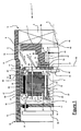
- the figure 1 illustrates an electric compressor in a longitudinal section of the latter.
- the internal components shown in this figure are shown partially but it should be understood that the axis A is an axis of symmetry beyond which these components take a mirror shape.
- the compressor 1 is an electric compressor in that it incorporates an electric motor 2 which drives a compression mechanism 3 in rotation.
- This compression mechanism 3 is of the type of compression screw (Scroll in English) or of the type with pallets or still of the piston type, these examples being given for illustrative purposes without limiting the scope of the invention.
- the compression mechanism 3 comprises fixed or moving parts, the latter being rotated by a drive device which comprises in a global manner a rotor 11 (part of the electric motor 2) integral with a shaft 4 which is extends longitudinally along the axis A.
- This shaft 4 therefore extends in the central portion of the compressor 1, substantially in the center of a main housing 5 which determines the external size of the compressor.
- This main housing 5 is a hollow circular aluminum or aluminum alloy part comprising a peripheral wall which delimits an internal volume 6 terminated on one side by a first end 14 and on the other by a second end 15. Both ends are open before mounting the other components of the compressor.
- the first end 14 of the housing 5 is closed by the compression mechanism 3.
- the compression mechanism 3 closes the housing being threaded at the end and inside of the latter.
- the second end 15 is closed by a secondary casing 16 which takes the form of a bowl and whose bottom 17 has a first face 18 facing the compression mechanism 3.
- An outgrowth 20 originates on the first face 18 in the form of a hollow tube which extends parallel to the axis A and towards the compression mechanism 3.
- the secondary housing 16 and the protrusion 20 are molded simultaneously from aluminum or an alloy of 'aluminum.
- This protrusion 20 comprises a docking edge 22 on which a stator 10 of the electric motor 2 bears.
- This stator 10 is mechanically fastened to the protrusion 20 by means of at least one fastening means, for example a 23.
- This excrescence 20 also comprises a circulation orifice 24 of the refrigerant 9 so as to be able to bypass the electric motor 2 through its center.
- This circulation orifice 24 is a hole which extends along an axis perpendicular to the axis A, but in another alternative, the hole may have an inclination other than orthogonal, for example 45 °, which promotes the circulation of the cooling fluid. in the internal volume of the compressor and thus limit the pressure losses.
- the secondary housing 16 comprises a second face 19 opposite the first face 18, that is to say facing the outside of the compressor 1.
- An edge 21 is placed perpendicularly to the bottom 17 and together defines a receiving zone of a control circuit 25 of the electric motor.
- This control circuit 25 is in this case an inverter (inverter in English) transforming a stream of continuous form coming from the vehicle into a stream of sinusoidal shape feeding the electric motor 2.
- the electric motor 2 In the internal volume 6 of the compressor, more particularly in the section dedicated to electrical devices, the electric motor 2 is installed.
- the latter comprises a stator 10 comprising coils 35 and a rotor 11 which rotates around, that is to say externally, the stator 10. It is therefore understood that the stator 10 is fixedly placed inside the rotor 11, the latter surrounding peripherally and externally the stator 10.
- the electric motor 2 placed in the main housing 5 separates the internal volume 6 into a first chamber 12 and a second chamber 26, the first chamber 12 receiving the refrigerant fluid in the gaseous state from the refrigerant circuit.
- the coolant enters the first chamber 12 by means of an inlet 13 in the main housing 5.
- This inlet takes the form of a pipe which extends radially outwardly of the main housing and a hole in the wall of the main housing to the right of the tubing.
- Permanent magnets 29 are secured to a support 27, and more particularly to an inner face 30 of the support.
- the latter has the shape of a bowl with a bottom 31 and a circumferential band 32.
- the bottom 31 is secured to the shaft 4 so that the support 27 rotates the shaft 4.
- This bottom 31 s' extends perpendicularly to the axis A and the circumferential band 32 extends orthogonally relative to the bottom 31, starting on the latter.
- the circumferential band 32 extends parallel to the axis A in the direction of the control device 25.
- the shaft 4 is a cylindrical tube comprising a first end 40 on the compression mechanism 3 and a second end 41 opposite the first end and facing the secondary housing 16.
- the shaft comprises also a shoulder 42 in which is housed the bottom 31 of the support 27.
- This shoulder comprises a means for prohibiting the rotation between the shaft 4 and the support 27 which takes the form of a key inserted between these two parts, complementary flats formed on these two parts or any other means for threading the bottom 31 on the shoulder 42 while prohibiting relative rotation between these two parts.
- the bottom 31 of the support 27 is secured to the end 41 of the shaft 4 by means of a fixing device 43. It is therefore understood that the shaft 4 ends substantially at the bottom 31 and that it is not extend in the center of the compressor 1 to the secondary housing 16.
- the shaft is a short shaft so as to release the central space of the compressor and thus facilitate the circulation of refrigerant 9.
- the fixing means 43 takes the form of a nut screwed onto the end of the shaft 4 so as to block any translation of the support 27 relative to the shaft 4.
- the shaft 4 further comprises a circumferential stop 44 which takes the form of a circlip or removable flexible ring taken in a groove 45 machined around the periphery of the shaft 4.
- This circumferential stop 44 limits the axial displacement of the shaft 4 relative to the first rotation means towards the electric motor 2, that is to say the opposite of the compression mechanism.
- the axial displacement in the other direction, that is to say towards the compression mechanism 3 is limited by the second rotation means 51.
- This pin 46 extends longitudinally along an axis parallel to the axis A but offset with respect thereto.
- a plate 7 extends in the internal volume 6 in a direction perpendicular to the axis A so as to separate the internal volume 6 into a part dedicated to the compression mechanism 3 and a part dedicated to electrical devices, in particular the electric motor 2.
- the plate 7 has at least one passage 8 which allows the refrigerant symbolized by the arrows 9 to flow from the part dedicated to the electrical devices, and more particularly from the second chamber 26, to the compression mechanism 3. Note all particularly that this passage 8 is made through the plate 7 at the junction between this plate and the housing main 5, that is to say the outer periphery of the plate 7.
- This plate 7 is a molded part with the main housing thus forming a one-piece piece of aluminum or aluminum alloy.
- the plate 7 is traversed from one side at its center by the shaft 4 constituting the drive device.
- This plate 7 comprises an outer wall 48 facing the compression mechanism 3, and this outer wall defines a housing 49 for receiving the first rotation means 47.
- This housing takes the form of a cylindrical well whose opening opens on the side of the compression mechanism 3.
- the housing 49 receives the first rotation means 47 which takes the form in this embodiment of a cylindrical bearing with double row of balls.
- This first rotation means 47 and in particular the double-row cylindrical ball bearing, has an axis of rotation coinciding with the axis A of the shaft 4.
- an outer ring of the bearing is mounted. by force in the housing 49 while an inner ring is slidably mounted on the shaft 4.
- the shaft 4 can move by translation in the first rotation means 47, it is necessary to limit this displacement. It is the role of the circumferential stop 44 which blocks a translation along the axis A of the shaft 4 towards the electric motor 2 and on which the first rotation means 47 is supported.
- the plate 7 also comprises an inner wall 50 opposite the outer wall 48. Between the inner wall 50 and the rotor 11 is interposed a second rotation means 51 which bears on one side on a blank 52 of the plate 7 and forming part of the inner wall 50 and the other on an outer face 53 of the support 27, that is to say facing the compression mechanism 3, at the bottom 31.
- the second rotation means 51 takes the form of a roller bearing, called a needle stop, each roller 54 of which rotates about an axis 55 perpendicular to the axis A of the shaft 4. Seen from the front, this Roller bearing takes the form of a flat disk constituted by a multitude of rollers whose axes of rotation all intersect at the same point. This flat disk forms the general plane of the second rotation means 51.
- the plane and the axis are inclined relative to each other so as to form an angle which in the example of the figure 1 is 90 °.
- the rotation means 51 is thus an axial bearing on which the bottom 31 of the support 27 bears.
- At least one opening 28 passes right through the bottom 31 of the support 27 constituting the rotor 11 so as to allow the circulation of a first portion of the refrigerant 9 from the circulation orifice 24, a second part passing in a gap between an outer peripheral wall of the stator 10 and an inner wall of the permanent magnets 29 and a third portion of the refrigerant flowing through the stator circulating between the coils 35.
- the support 27 comprises between three and six openings.
- the multiplicity of permanent magnets 29 has a first lateral edge 56 on the compression mechanism side and a second lateral edge 57 facing the secondary housing 16.
- the stator On its side, the stator comprises a first lateral blank 58 oriented towards the compression mechanism and a second side blank 59 oriented towards the secondary housing 16. It can be seen in the figure that the multiplicity of permanent magnets 29 and the stator are not aligned on the same axis. Indeed, the first lateral blank 58 is offset with respect to the first lateral edge 56 according to a distance illustrated by the reference B.
- the figure 2 shows an identical assembly with the exception of the first rotation means 47.
- this rotation means takes the form of a single-row ball bearing installed in the receiving housing 49, which makes it possible to shorten the rotation. shaft 4 and thus obtain a compressor of restricted length.
- the translation of the shaft 4 is limited on one side by the second rotation means and on the other side by the flexible ring 44.
- the figure 3 is an example of the invention where the second rotation means 51 is installed differently. Whereas on the example of figures 1 and 2 the second rotation means 51 is interposed between the bottom 31 of the support 27 and the blank 52 of the plate 7, in the example of the figure 3 , the second rotation means is interposed between the shaft 4 and the same blank of the plate 7.
- the shaft 4 comprises a disc 60 integral with the latter and formed on the shaft between the groove 45 and the shoulder 42 which receives the support 27.
- This disc has a diameter greater than that of the shaft 4.
- This disc 60 is delimited by a cylindrical outer edge 61, a first face 62 against which the bottom 31 of the support 27 bears after clamping the fixing means 43 and a second face 63 against which the second rotation means 51 is supported.
- the rollers 54 of the second rotation means 51 thus rotate both against the second face 63 of the disc 60 and against the blank 52 of the plate 7.
- Such a solution offers a simplified management of taking into account the tolerances of the components having an impact on the second rotation means 51. Indeed, the presence of the disc 60 secured to the shaft 4 avoids taking into account the dimensional tolerances of the bottom 31 of the support 27 as well as the fixing tolerances inherent in the fastening means 43.
- FIG 4 A third variant of the invention is illustrated in figure 4 .
- the second rotation means 51 takes the form of a plain bearing 65 illustrated in this figure by a strong line.
- the disc 60, and more particularly the second face 63 of this disc, is in contact with the blank 52 of the plate 7 via the plain bearing 65.
- this sliding bearing 65 is a treatment of the contact surface so as to facilitate the sliding of the disk 60 on the sidewall 52 of the plate 7 despite the axial forces exerted on the shaft 4 towards the mechanism
- This surface treatment is performed on the second face 63 of the disc 60 and / or on the side 52 of the plate 7.
- This sliding bearing 65 thus ensures the rotation between the disc 60 and the flank 52 of the plate 7 without wear of one or the other of these parts.
- the sliding bearing 65 has been described above as being interposed between the disk 60 and the sidewall 52 of the plate 7, but the invention also covers the case where a sliding bearing is interposed directly between the support 27 and the sidewall 52, that is to say in place of the needle bearing mentioned in relation to the figures 1 and 2 .
- the Figures 3 and 4 also show the existence of a lubrication channel 64 formed between the plate 7 and the shaft 4 as well as between the blank 52 and the second face 63 of the disk 60 so as to allow a circulation of a lubricant of the housing 49 to the second chamber 26 and thus lubricate the first rotation means 47 and the second rotation means 51, in particular the smooth bearing ( figure 4 ) or the needle bearing ( figure 3 ).
- the structure of the invention facilitates the circulation of the coolant 9 in the compressor 1.
- This fluid enters through the inlet 13 and the first part of the refrigerant flows towards the center of the compressor in the direction of the circulation orifice 24.
- this part of the coolant 9 licks the second side blank 59 of the stator 10 and heat exchanges with the latter so as to cool it.
- the second part of the coolant 9 which circulates between the rotor 11 and the stator 10 licks the outer peripheral wall of the stator 10 and thermally exchanges with the latter.
- the third part of the refrigerant, passing through the stator exchanges with the coils 35 and cools them.
- the coolant 9 circulates in the space released by the shaft to be directed towards the second chamber 26. Finally, the presence of the openings in the bottom 31 concentrates the first and the second chamber. second part of the coolant 9 where it exchanges thermally with the first side blank 58 of the stator 10 which faces the compression mechanism 3.
Description
Le secteur technique de la présente invention est celui des compresseurs constitutifs d'un circuit de fluide réfrigérant équipant un véhicule automobile.The technical sector of the present invention is that of compressors constituting a refrigerant circuit fitted to a motor vehicle.
Le fluide réfrigérant est classiquement mis en circulation à l'intérieur d'un circuit de climatisation par l'intermédiaire d'un compresseur. Dans les véhicules équipés d'un moteur à combustion interne, ce compresseur est de type mécanique car sa rotation est entraînée au moyen d'une poulie reliée au moteur à combustion interne par une courroie.The refrigerant fluid is conventionally circulated inside an air conditioning circuit via a compressor. In vehicles equipped with an internal combustion engine, this compressor is mechanical type because its rotation is driven by means of a pulley connected to the internal combustion engine by a belt.
Le nombre de véhicules hybrides, c'est-à-dire à moteur à combustion interne couplé à un moteur électrique, ou tout électrique, c'est-à-dire exclusivement propulsé par un moteur électrique, est en constante augmentation du fait de la raréfaction des énergies fossiles qui alimentent les véhicules équipés de moteur à combustion interne.The number of hybrid vehicles, that is to say with internal combustion engine coupled to an electric motor, or all electric, that is to say exclusively powered by an electric motor, is constantly increasing because of the rarefaction of fossil fuels that fuel vehicles equipped with internal combustion engines.
L'énergie mécanique fournie habituellement par le moteur à combustion interne est donc moins disponible ou complètement indisponible pour le cas des véhicules tout électrique.The mechanical energy usually supplied by the internal combustion engine is therefore less available or completely unavailable for the case of all-electric vehicles.
Des compresseurs entrainés par un moteur électrique dédié existent dans la littérature. Ce moteur électrique est constitué d'un stator périphérique à l'intérieur duquel est installé un rotor. Autrement dit, le rotor est placé à l'intérieur et au centre du stator.Compressors driven by a dedicated electric motor exist in the literature. This electric motor consists of a peripheral stator inside which is installed a rotor. In other words, the rotor is placed inside and in the center of the stator.
Ce type de moteur électrique a été remplacé par un moteur électrique à rotor externe, où le rotor tourne périphériquement autour d'un stator installé fixement au centre du rotor. Le document
Cependant, les dimensions des compresseurs de l'art antérieur ne sont pas optimisées, en particulier en ce qui concerne le positionnement de l'arbre relié au rotor.However, the dimensions of the compressors of the prior art are not optimized, in particular as regards the positioning of the shaft connected to the rotor.
Par ailleurs, la circulation de fluide réfrigérant à l'intérieur du compresseur est inadaptée au cas où l'entrée et la sortie de fluide réfrigérant sont aux extrémités du compresseur. Dans un tel cas, le fluide réfrigérant doit contourner le moteur électrique. Cette circulation particulière de fluide réfrigérant au travers du compresseur n'a pas été prise en compte dans les documents
Un autre inconvénient de l'état de la technique cité ci-dessus réside dans le fait que le stator n'est pas refroidit car ce dernier n'est pas en contact avec ce fluide réfrigérant en mouvement dans le compresseur.Another disadvantage of the state of the art cited above resides in the fact that the stator is not cooled because the latter is not in contact with this cooling fluid moving in the compressor.
Le but de la présente invention est donc de résoudre les inconvénients décrits ci-dessus principalement en modifiant la liaison entre l'arbre central et le boîtier, ce qui permet de raccourcir cet arbre et ainsi libérer la partie centrale du compresseur au niveau du stator. Ceci permet de gagner en encombrement externe puisque le stator peut être réduit et occuper l'espace utilisé par l'arbre dans l'art antérieur. Ces espaces libérés peuvent également être utilisés pour la circulation du fluide réfrigérant sans pour autant altérer la perte de charge interne et tout en refroidissant le stator du moteur électrique.The object of the present invention is therefore to solve the disadvantages described above mainly by modifying the connection between the central shaft and the housing, thereby shortening the shaft and thus release the central portion of the compressor at the stator. This makes it possible to gain external bulk since the stator can be reduced and occupy the space used by the shaft in the prior art. These released spaces can also be used for the circulation of the refrigerant without altering the internal pressure drop and while cooling the stator of the electric motor.
L'invention a donc pour objet un compresseur électrique comprenant un mécanisme de compression entrainé en rotation par un dispositif d'entrainement traversant un boîtier principal qui délimite un volume interne à l'intérieur duquel est installé un moteur électrique, le moteur électrique comprenant un stator et un rotor qui s'étend au moins partiellement à la périphérie externe du stator, ledit dispositif d'entraînement comprenant le rotor solidaire d'un arbre qui passe au travers d'un plateau solidaire du boîtier principal, caractérisé en ce qu'il comprend un premier moyen de rotation entre l'arbre et le plateau et un second moyen de rotation entre le dispositif d'entraînement et le plateau.The subject of the invention is therefore an electric compressor comprising a compression mechanism driven in rotation by a drive device passing through a main housing which delimits an internal volume inside which an electric motor is installed, the electric motor comprising a stator and a rotor which extends at least partially to the outer periphery of the stator, said drive device comprising the rotor integral with a shaft which passes through a plate secured to the main housing, characterized in that it comprises first means of rotation between the shaft and the plate and second means of rotation between the driving device and the plate.
On comprend ici que le second moyen de rotation est interposé entre le plateau et l'une quelconque des pièces constitutives du dispositif d'entraînement, par exemple l'arbre mais aussi un support constitutif du rotor.It is understood here that the second rotation means is interposed between the plate and any of the component parts of the drive device, for example the shaft but also a constituent support of the rotor.
Les avantages évoqués ci-dessus sont rendus possibles grâce au fait que le mouvement radial de l'arbre du compresseur selon l'invention est maintenu par un premier moyen de rotation alors que le mouvement axial de cet arbre est limité par un second moyen de rotation, ces deux moyens de rotation étant en appui sur le plateau constitutif du boîtier du compresseur.The advantages mentioned above are made possible by the fact that the radial movement of the compressor shaft according to the invention is maintained by a first rotation means while the axial movement of this shaft is limited by a second rotation means. these two rotating means being in abutment on the constituent plate of the compressor housing.
Selon une première caractéristique de l'invention, le premier moyen de rotation présente un axe de rotation et le deuxième moyen de rotation s'étend dans un plan, ledit plan et ledit axe s'étendant angulairement l'un par rapport à l'autre.According to a first feature of the invention, the first means of rotation has an axis of rotation and the second rotation means extends in a plane, said plane and said axis extending angularly relative to each other.
Selon une deuxième caractéristique de l'invention, le plateau comprend une paroi interne tournée vers le moteur et ledit rotor comprend un support sur lequel est solidarisé une multiplicité d'aimants permanents, ledit second moyen de rotation étant interposé entre le support et la paroi.According to a second characteristic of the invention, the plate comprises an inner wall facing towards the motor and said rotor comprises a support on which is fixed a multiplicity of permanent magnets, said second means of rotation being interposed between the support and the wall.
Selon une variante, le plateau comprend une paroi interne tournée vers le moteur électrique et l'arbre comprend un disque, ledit second moyen de rotation étant interposé entre ledit disque et la paroi. De manière avantageuse, le disque fixé à demeure sur l'arbre, soit en rapportant le disque et en le soudant sur l'arbre, soit en usinant directement le disque directement dans la masse avec l'arbre.According to a variant, the plate comprises an inner wall facing towards the electric motor and the shaft comprises a disk, said second means of rotation being interposed between said disk and the wall. Advantageously, the disk fixedly attached to the shaft, either by bringing the disk and welding it on the shaft, or by directly machining the disk directly in the mass with the shaft.
Selon une autre caractéristique de l'invention, le plateau comprend une paroi externe tournée vers le mécanisme de compression, ladite paroi externe délimitant un logement de réception du premier moyen de rotation.According to another characteristic of the invention, the plate comprises an outer wall facing the compression mechanism, said outer wall delimiting a receiving housing of the first rotation means.
Selon encore une caractéristique de l'invention, le support comprend un fond solidarisé sur l'arbre et qui s'étend radialement par rapport à l'arbre, ledit fond comprenant au moins une ouverture pour la circulation d'un fluide réfrigérant.According to another characteristic of the invention, the support comprises a bottom secured to the shaft and which extends radially relative to the shaft, said bottom comprising at least one opening for the circulation of a refrigerant.
Selon encore une autre caractéristique de l'invention, l'arbre comporte une butée circonférentielle contre laquelle le premier moyen de rotation prend appui.According to yet another characteristic of the invention, the shaft comprises a circumferential stop against which the first rotation means bears.
Avantageusement, la multiplicité d'aimants permanents et le stator sont désaxés, ledit stator étant décalé vers le mécanisme de compression.Advantageously, the multiplicity of permanent magnets and the stator are off-axis, said stator being shifted towards the compression mechanism.
Le premier moyen de rotation est un roulement à rangée unique de billes ou un roulement à rangée double de billes, ce premier moyen de rotation étant un moyen de rotation axial.The first rotation means is a single-row ball bearing or a double-row ball bearing, said first rotating means being a means of axial rotation.
De son côté, le second moyen de rotation est un roulement à rouleaux, ce second moyen de rotation étant un moyen de rotation axial.For its part, the second rotation means is a roller bearing, this second rotation means being a means of axial rotation.
Alternativement, le second moyen de rotation est un palier lisse, l'utilisation de ce dernier étant par exemple envisagée en présence du disque solidarisé sur l'arbre.Alternatively, the second rotation means is a sliding bearing, the use of the latter being for example envisaged in the presence of the disc secured to the shaft.
Avantageusement encore, le moteur électrique sépare le volume interne en délimitant d'un côté une première chambre et de l'autre une deuxième chambre, ladite première chambre étant alimentée en fluide réfrigérant par une entrée pratiquée dans le boîtier principal alors que la deuxième chambre alimente le mécanisme de compression via un passage traversant le plateau.Advantageously, the electric motor separates the internal volume delimiting on one side a first chamber and the other a second chamber, said first chamber being supplied with refrigerant fluid through an inlet made in the main housing while the second chamber feeds the compression mechanism via a passage passing through the plate.
Un tout premier avantage de l'invention réside dans la possibilité de faire circuler le fluide réfrigérant d'une extrémité à l'autre du compresseur en passant par le centre de ce dernier, ce qui permet de concevoir un compresseur électrique utilisant un moteur électrique à rotor externe tout en maintenant des dimensions réduites, en particulier en ce qui concerne son diamètre mais également sa longueur.A first advantage of the invention lies in the ability to circulate the refrigerant fluid from one end to the other of the compressor through the center of the latter, which allows to design an electric compressor using an electric motor. external rotor while maintaining reduced dimensions, in particular as regards its diameter but also its length.
Un autre avantage réside dans la possibilité de refroidir le moteur électrique en forçant la circulation du fluide réfrigérant autour du stator.Another advantage lies in the possibility of cooling the electric motor by forcing the circulation of the refrigerant around the stator.
D'autres caractéristiques, détails et avantages de l'invention ressortiront plus clairement à la lecture de la description donnée ci-après à titre indicatif en relation avec les dessins dans lesquels :
- la
figure 1 est une vue en coupe d'un compresseur selon l'invention, - la
figure 2 est une vue partielle d'une variante de lafigure 1 , - la
figure 3 est une vue partielle d'une deuxième variante de réalisation de lafigure 1 , - la
figure 4 est une vue partielle d'une troisième variante de réalisation de lafigure 1 .
- the
figure 1 is a sectional view of a compressor according to the invention, - the
figure 2 is a partial view of a variant of thefigure 1 , - the
figure 3 is a partial view of a second embodiment variant of thefigure 1 , - the
figure 4 is a partial view of a third embodiment variant of thefigure 1 .
Il faut noter que les figures exposent l'invention de manière détaillée et suffisante, lesdites figures peuvent bien entendu servir à mieux définir l'invention le cas échéant.It should be noted that the figures expose the invention in a detailed and sufficient manner, said figures can of course be used to better define the invention where appropriate.
La
Le compresseur 1 est un compresseur électrique en ce sens qu'il intègre un moteur électrique 2 qui entraîne en rotation un mécanisme de compression 3. Ce mécanisme de compression 3 est du type vis de compression (Scroll en anglais) ou du type à palettes ou encore du type à pistons, ces exemples étant donnés à titre illustratif sans pour autant limiter la portée de l'invention.The compressor 1 is an electric compressor in that it incorporates an electric motor 2 which drives a compression mechanism 3 in rotation. This compression mechanism 3 is of the type of compression screw (Scroll in English) or of the type with pallets or still of the piston type, these examples being given for illustrative purposes without limiting the scope of the invention.
Le mécanisme de compression 3 comprend des pièces fixes ou mobiles, ces dernières étant mises en rotation par un dispositif d'entraînement qui comprend d'une manière globale un rotor 11 (partie du moteur électrique 2) solidaire d'un arbre 4 qui s'étend longitudinalement selon l'axe A. Cet arbre 4 s'étend donc dans la partie centrale du compresseur 1, sensiblement au centre d'un boîtier principal 5 qui détermine l'encombrement externe du compresseur.The compression mechanism 3 comprises fixed or moving parts, the latter being rotated by a drive device which comprises in a global manner a rotor 11 (part of the electric motor 2) integral with a
Ce boîtier principal 5 est une pièce en aluminium ou en alliage d'aluminium de forme circulaire creuse comprenant une paroi périphérique qui délimite un volume interne 6 terminé d'un côté par une première extrémité 14 et de l'autre par une deuxième extrémité 15. Ces deux extrémités sont ouvertes avant montage des autres composants du compresseur.This
La première extrémité 14 du boîtier 5 est fermée par le mécanisme de compression 3. Dans l'exemple de la figure, le mécanisme de compression 3 ferme le boîtier en étant enfilé au niveau de l'extrémité et à l'intérieur de ce dernier.The
La deuxième extrémité 15 est quant à elle obturée par un boîtier secondaire 16 qui prend la forme d'une cuvette et dont le fond 17 présente une première face 18 tournée vers le mécanisme de compression 3. Une excroissance 20 prend naissance sur la première face 18 sous la forme d'un tube creux qui s'étend parallèlement à l'axe A et en direction du mécanisme de compression 3. Le boîtier secondaire 16 et l'excroissance 20 sont moulés simultanément à partir d'aluminium ou d'un alliage d'aluminium. Cette excroissance 20 comprend un bord d'accostage 22 sur lequel vient prendre appui un stator 10 du moteur électrique 2. Ce stator 10 est solidarisé mécaniquement sur l'excroissance 20 à l'aide d'au moins un moyen de fixation, par exemple une vis 23. Cette excroissance 20 comprend également un orifice de circulation 24 du fluide réfrigérant 9 de manière à pouvoir contourner le moteur électrique 2 en passant par son centre. Cet orifice de circulation 24 est un trou qui s'étend selon un axe perpendiculaire à l'axe A mais dans une autre alternative, le trou peut présenter une inclinaison autre qu'orthogonale, par exemple 45° ce qui favorise la circulation du fluide réfrigérant dans le volume interne du compresseur et limite ainsi les pertes de charges.The
Le boîtier secondaire 16 comprend une deuxième face 19 opposée à la première face 18, c'est-à-dire tournée vers l'extérieur du compresseur 1. Un bord 21 est placé perpendiculairement au fond 17 et délimite ensemble une zone de réception d'un circuit de commande 25 du moteur électrique. Ce circuit de commande 25 est dans le cas présent un onduleur (Inverter en anglais) transformant un courant de forme continue en provenance du véhicule en un courant de forme sinusoïdale alimentant le moteur électrique 2.The
Dans le volume interne 6 du compresseur, plus particulièrement dans la partie dédiée aux dispositifs électriques, est installé le moteur électrique 2. Ce dernier comprend un stator 10 comportant des bobines 35 et un rotor 11 qui tourne autour, c'est-à-dire à l'extérieur, du stator 10. On comprend donc que le stator 10 est placé de manière fixe à l'intérieur du rotor 11, ce dernier entourant de manière périphérique et externe le stator 10.In the
Le moteur électrique 2 placé dans le boîtier principal 5 sépare le volume interne 6 en une première chambre 12 et en une deuxième chambre 26, la première chambre 12 recevant le fluide réfrigérant à l'état gazeux en provenance du circuit de réfrigérant.The electric motor 2 placed in the
Le fluide réfrigérant pénètre dans la première chambre 12 au moyen d'une entrée 13 pratiquée dans le boîtier principal 5. Cette entrée prend la forme d'une tubulure qui s'étend radialement vers l'extérieur du boîtier principal et d'un trou pratiqué dans la paroi du boîtier principal au droit de la tubulure.The coolant enters the
Des aimants permanents 29 sont solidarisés sur un support 27, et plus particulièrement sur une face interne 30 du support. Ce dernier présente la forme d'un bol avec un fond 31 et une bande circonférentielle 32. Le fond 31 est solidaire de l'arbre 4 de sorte à ce que le support 27 entraîne en rotation l'arbre 4. Ce fond 31 s'étend donc perpendiculairement à l'axe A et la bande circonférentielle 32 s'étend quant à elle orthogonalement par rapport au fond 31, en prenant naissance sur ce dernier. Autrement dit, la bande circonférentielle 32 s'étend parallèlement à l'axe A en direction du dispositif de commande 25.
L'arbre 4 est un tube cylindrique comprenant une première extrémité 40 côté mécanisme de compression 3 et une deuxième extrémité 41 opposée à la première extrémité et faisant face au boîtier secondaire 16. L'arbre comprend également un épaulement 42 dans lequel se loge le fond 31 du support 27. Cet épaulement comprend un moyen pour interdire la rotation entre l'arbre 4 et le support 27 qui prend la forme d'une clavette intercalée entre ces deux pièces, de méplats complémentaires formés sur ces deux pièces ou tout autre moyen permettant d'enfiler le fond 31 sur l'épaulement 42 tout en interdisant toute rotation relative entre ces deux pièces.The
Le fond 31 du support 27 est solidarisé sur l'extrémité 41 de l'arbre 4 au moyen d'un dispositif de fixation 43. On comprend donc que l'arbre 4 se termine sensiblement au droit du fond 31 et qu'il ne s'étend pas au centre du compresseur 1 vers le boîtier secondaire 16. L'arbre est donc un arbre court de sorte à libérer l'espace central du compresseur et ainsi faciliter la circulation de fluide réfrigérant 9. Dans l'exemple de la
L'arbre 4 comprend encore une butée circonférentielle 44 qui prend la forme d'un circlip ou anneau flexible amovible pris dans une gorge 45 usinée sur le pourtour de l'arbre 4. Cette butée circonférentielle 44 limite le déplacement axial de l'arbre 4 par rapport au premier moyen de rotation en direction du moteur électrique 2, c'est-à-dire à l'opposé du mécanisme de compression. Le déplacement axial dans l'autre direction, c'est-à-dire vers le mécanisme de compression 3 est limité par le second moyen de rotation 51.The
De la première extrémité 40 débouche un pion d'actionnement 46 du mécanisme de compression 3. Ce pion 46 s'étend longitudinalement selon un axe parallèle à l'axe A mais décalé par rapport à ce dernier.From the
Un plateau 7 s'étend dans le volume interne 6 selon une direction perpendiculaire à l'axe A de sorte à séparer le volume interne 6 en une partie dédiée au mécanisme de compression 3 et une partie dédiée aux dispositifs électriques, en particulier le moteur électrique 2. Le plateau 7 présente au moins un passage 8 qui permet au fluide réfrigérant symbolisé par les flèches 9 de circuler de la partie dédiée aux dispositifs électriques, et plus particulièrement de la deuxième chambre 26, vers le mécanisme de compression 3. On notera tout particulièrement que ce passage 8 est effectué au travers du plateau 7 au niveau de la jonction entre ce plateau et le boîtier principal 5, c'est-à-dire à la périphérie externe du plateau 7. Ce plateau 7 est une pièce issue de moulage avec le boîtier principal formant ainsi une pièce monobloc en aluminium ou en alliage d'aluminium.A
Le plateau 7 est traversé de part en part en son centre par l'arbre 4 constitutif du dispositif d'entraînement.The
Ce plateau 7 comprend une paroi externe 48 tournée vers le mécanisme de compression 3, et cette paroi externe délimite un logement 49 de réception du premier moyen de rotation 47. Ce logement prend la forme d'un puits cylindrique dont l'ouverture débouche du côté du mécanisme de compression 3. Le logement 49 reçoit le premier moyen de rotation 47 qui prend la forme dans ce mode de réalisation d'un roulement cylindrique à double rangée de billes. Ce premier moyen de rotation 47, et en particulier le roulement cylindrique à double rangée de billes, présente un axe de rotation confondu avec l'axe A de l'arbre 4. Dans le cas d'espèce, une bague externe du roulement est montée à force dans le logement 49 alors qu'une bague interne est montée coulissante sur l'arbre 4. Comme l'arbre 4 peut se déplacer par translation dans le premier moyen de rotation 47, il est nécessaire de limiter ce déplacement. C'est le rôle de la butée circonférentielle 44 qui bloque une translation selon l'axe A de l'arbre 4 vers le moteur électrique 2 et sur laquelle le premier moyen de rotation 47 s'appuie.This
Le plateau 7 comprend également une paroi interne 50 opposée à la paroi externe 48. Entre la paroi interne 50 et le rotor 11 est intercalé un second moyen de rotation 51 qui prend appui d'un côté sur un flan 52 du plateau 7 et faisant partie de la paroi interne 50 et de l'autre sur une face externe 53 du support 27, c'est-à-dire tournée vers le mécanisme de compression 3, au niveau du fond 31.The
Sur la
On notera particulièrement que le plan dans lequel s'étend le second moyen de rotation 51 croise l'axe de rotation du premier moyen de rotation 47, ainsi que l'axe A car ces deux derniers sont confondus. Le plan et l'axe sont donc inclinés l'un par rapport à l'autre de manière à former un angle qui dans l'exemple de la
Au moins une ouverture 28 traverse de part en part le fond 31 du support 27 constitutif du rotor 11 de sorte à autoriser la circulation d'une première partie du fluide réfrigérant 9 en provenance de l'orifice de circulation 24, d'une deuxième partie passant dans un interstice entre une paroi périphérique externe du stator 10 et une paroi interne des aimants permanents 29 et d'une troisième partie du fluide réfrigérant passant au travers du stator en circulant entre les bobines 35. Pour limiter les pertes de charges à haute vitesse, le support 27 comprend entre trois et six ouvertures.At least one
La multiplicité d'aimants permanents 29 présente un premier bord latéral 56 côté mécanisme de compression et un second bord latéral 57 faisant face au boîtier secondaire 16. De son côté, le stator comporte un premier flan latéral 58 orienté vers le mécanisme de compression et un second flan latéral 59 orienté vers le boîtier secondaire 16. On voit sur la figure que la multiplicité d'aimants permanents 29 et le stator ne sont pas alignés sur un même axe. En effet, le premier flan latéral 58 est décalé par rapport au premier bord latéral 56 selon une distance illustrée par la référence B.The multiplicity of
Cette structure se traduit par un avantage surprenant. En effet, l'attraction magnétique entre le rotor et le stator provoque une attirance du rotor vers le stator, ce qui se traduit par une force d'appui du support 27 sur le second moyen de rotation 51. Ainsi, un appui continu est exercé sur les rouleaux 54 ce qui évite des bruits de fonctionnement quand le second moyen de rotation 51 (butée à aiguilles) n'est pas constamment poussé par le rotor.This structure results in a surprising advantage. Indeed, the magnetic attraction between the rotor and the stator causes an attraction of the rotor towards the stator, which results in a bearing force of the
La
La
Plus particulièrement, l'arbre 4 comprend un disque 60 solidaire de ce dernier et formé sur l'arbre entre la gorge 45 et l'épaulement 42 qui reçoit le support 27. Ce disque présente un diamètre supérieur à celui de l'arbre 4. Ce disque 60 est délimité par un bord externe cylindrique 61, une première face 62 contre laquelle le fond 31 du support 27 prend appui après serrage du moyen de fixation 43 et une seconde face 63 contre laquelle le second moyen de rotation 51 prend appui. Les rouleaux 54 du second moyen de rotation 51 tourne donc à la fois contre la seconde face 63 du disque 60 et contre le flan 52 du plateau 7.More particularly, the
Une telle solution offre une gestion simplifiée de la prise en compte des tolérances des composants ayant un impact sur le second moyen de rotation 51. En effet, la présence du disque 60 solidaire de l'arbre 4 évite de prendre en considération les tolérances dimensionnelles du fond 31 du support 27 ainsi que les tolérances de fixation inhérentes au moyen de fixation 43.Such a solution offers a simplified management of taking into account the tolerances of the components having an impact on the second rotation means 51. Indeed, the presence of the
Une troisième variante de l'invention est illustrée à la
De manière plus détaillée, ce palier lisse 65 est un traitement de la surface de contact de sorte à faciliter le glissement du disque 60 sur le flanc 52 du plateau 7 malgré les efforts axiaux qui s'exercent sur l'arbre 4 en direction du mécanisme de compression 3. Ce traitement de surface est effectué sur la seconde face 63 du disque 60 et/ou sur le flanc 52 du plateau 7.In more detail, this sliding
Ce traitement de surface comprend trois couches :
- une couche de base formée par la seconde face 63 du disque, dans ce cas fabriqué en acier, - une couche intermédiaire ou couche frittée comportant des particules solides de lubrifiant mélangées à coeur avec un matériau synthétique ou du bronze,
- une couche de frottement ou de glissement comprenant un lubrifiant solide tel que le PTFE (Polytetrafluoroethylene).
- a base layer formed by the
second face 63 of the disc, in this case made of steel, an intermediate layer or sintered layer comprising solid particles of lubricant mixed at heart with a synthetic material or bronze, - a friction or slip layer comprising a solid lubricant such as PTFE (Polytetrafluoroethylene).
Ce palier lisse 65 garantit ainsi la rotation entre le disque 60 et le flanc 52 du plateau 7 sans usure de l'une ou l'autre de ces pièces.This sliding
Le palier lisse 65 a été décrit ci-dessus comme étant interposé entre le disque 60 et le flanc 52 du plateau 7 mais l'invention couvre aussi le cas où un palier lisse est interposé directement entre le support 27 et le flanc 52, c'est-à-dire en lieu et place du roulement à aiguilles évoqué en rapport avec les
Les
La structure de l'invention facilite la circulation du fluide réfrigérant 9 dans le compresseur 1. Ce fluide pénètre par l'entrée 13 et la première partie du fluide réfrigérant se dirige vers le centre du compresseur en direction de l'orifice de circulation 24. Ce faisant, cette partie du fluide réfrigérant 9 lèche le second flan latéral 59 du stator 10 et échange thermiquement avec ce dernier de sorte à le refroidir. La deuxième partie du fluide réfrigérant 9 qui circule entre le rotor 11 et le stator 10 lèche la paroi périphérique externe du stator 10 et échange thermiquement avec ce dernier. Enfin, la troisième partie du fluide réfrigérant, en passant au travers du stator, échange avec les bobines 35 et refroidit ces dernières.
Grâce à l'arbre 4 raccourci selon l'invention, le fluide réfrigérant 9 circule dans l'espace libéré par l'arbre pour être dirigé vers la deuxième chambre 26. Enfin, la présence des ouvertures dans le fond 31 concentre la premier et la deuxième partie du fluide réfrigérant 9 où il échange thermiquement avec le premier flan latéral 58 du stator 10 qui fait face au mécanisme de compression 3.The structure of the invention facilitates the circulation of the
Thanks to the shortened
Claims (11)
- Electric compressor (1) comprising a compression mechanism (3) rotated by a drive device that extends through a main casing (5) delimiting an internal volume (6) inside which an electric motor (2) is installed, the electric motor including a stator (10) and a rotor (11), which extends at least partially on the outer periphery of the stator (10), said drive device including the rotor (11), solidly connected to a shaft (4), which extends through a plate (7) solidly connected to the main casing (5), and a first rotation means (47) between the shaft (4) and the plate (7) characterized in that it includes a second rotation means (51) between the drive device and the plate (7), the first rotation means (47) has an axis of rotation and the second rotation means (51) extends in a plane, said plane and said axis extending angularly one in relation to the other, and the rotor (11) includes a support (27) to which a multiplicity of permanent magnets (29) is solidly connected, said multiplicity of permanent magnets (29) and the stator (10) being offset, said stator being offset toward the compression mechanism (3).
- Compressor according to Claim 1, in which the plate (7) includes an inner wall (50) turned toward the electric motor (2) and said rotor (11) includes a support (27) to which a multiplicity of permanent magnets (29) is solidly connected, said second rotation means (51) being interposed between the support (27) and the wall (50).
- Compressor according to Claim 1, in which the plate (7) includes an inner wall (50) turned toward the electric motor (2) and the shaft (4) includes a disk (60), said second rotation means (51) being interposed between said disk (60) and the wall (50).
- Compressor according to any one of Claims 1 to 3, in which the plate (7) includes an outer wall (48) turned toward the compression mechanism (3), said outer wall (48) delimiting a housing (49) for accommodating the first rotation means (47).
- Compressor according to any one of the preceding claims, in which the rotor (11) includes a support (27) to which a multiplicity of permanent magnets (29) is solidly connected, said support (27) includes an end wall (31) solidly connected to the shaft (4) and which extends radially in relation to the shaft (4), said end wall including at least one opening (28) for the circulation of a coolant (9).
- Compressor according to any one of Claims 1 to 5, in which the shaft (4) incorporates a circumferential stop (44) against which the first rotation means (47) bears.
- Compressor according to any one of the preceding claims, in which the first rotation means (47) is a single-row ball bearing.
- Compressor according to any one of Claims 1 to 6, in which the first rotation means (47) is a double-row ball bearing.
- Compressor according to any one of the preceding claims, in which the second rotation means (51) is a roller bearing.
- Compressor according to any one of Claims 1 to 8, in which the second rotation means (51) is a plain bearing (65).
- Compressor according to any one of the preceding claims, in which the electric motor (2) separates the internal volume (6), delimiting a first chamber (12) on one side and a second chamber (26) on the other, said first chamber (12) being supplied with coolant (9) through an inlet (13) made in the main casing (5), while the second chamber (26) supplies the compression mechanism through a passage (8).
Applications Claiming Priority (2)
| Application Number | Priority Date | Filing Date | Title |
|---|---|---|---|
| FR1002529A FR2961268B1 (en) | 2010-06-15 | 2010-06-15 | ELECTRICAL COMPRESSOR WITH SHORT SHAFT |
| PCT/EP2011/002943 WO2011157411A2 (en) | 2010-06-15 | 2011-06-15 | Short-shaft electric compressor |
Publications (2)
| Publication Number | Publication Date |
|---|---|
| EP2582979A2 EP2582979A2 (en) | 2013-04-24 |
| EP2582979B1 true EP2582979B1 (en) | 2015-09-16 |
Family
ID=43755076
Family Applications (1)
| Application Number | Title | Priority Date | Filing Date |
|---|---|---|---|
| EP11741093.6A Not-in-force EP2582979B1 (en) | 2010-06-15 | 2011-06-15 | Elektrisch angetriebener verdichter mit kurzer welle |
Country Status (4)
| Country | Link |
|---|---|
| US (1) | US20130156617A1 (en) |
| EP (1) | EP2582979B1 (en) |
| FR (1) | FR2961268B1 (en) |
| WO (1) | WO2011157411A2 (en) |
Families Citing this family (6)
| Publication number | Priority date | Publication date | Assignee | Title |
|---|---|---|---|---|
| TWM454336U (en) * | 2012-12-07 | 2013-06-01 | yong-qi Lv | Compressor of air conditioner on car |
| JP6469575B2 (en) * | 2013-09-03 | 2019-02-13 | パナソニック アプライアンシズ リフリジレーション デヴァイシズ シンガポール | Hermetic compressor and refrigerator or refrigeration apparatus equipped with the same |
| CN105673508A (en) * | 2014-11-18 | 2016-06-15 | 上海日立电器有限公司 | Rolling rotor type compressor |
| KR102227089B1 (en) * | 2014-12-18 | 2021-03-12 | 엘지전자 주식회사 | Compressor |
| WO2017033413A1 (en) * | 2015-08-25 | 2017-03-02 | パナソニックIpマネジメント株式会社 | Enclosed compressdor and refrigeration device |
| JP6445948B2 (en) * | 2015-09-10 | 2018-12-26 | 日立ジョンソンコントロールズ空調株式会社 | Screw compressor |
Family Cites Families (12)
| Publication number | Priority date | Publication date | Assignee | Title |
|---|---|---|---|---|
| JPS581278B2 (en) * | 1980-04-05 | 1983-01-10 | サンデン株式会社 | Scroll compressor |
| DE4408719C1 (en) * | 1994-03-15 | 1995-07-06 | Volkswagen Ag | Combined electric generator and motor for vehicle hybrid drive |
| US6419457B1 (en) * | 2000-10-16 | 2002-07-16 | Copeland Corporation | Dual volume-ratio scroll machine |
| JP2003056461A (en) * | 2001-02-15 | 2003-02-26 | Denso Corp | Complex driving system for compressor |
| JP3967116B2 (en) * | 2001-04-24 | 2007-08-29 | 株式会社日本自動車部品総合研究所 | Compressor compound drive |
| JP2003341352A (en) * | 2002-05-29 | 2003-12-03 | Toyota Industries Corp | Hybrid compressor system |
| JP2005264780A (en) * | 2004-03-17 | 2005-09-29 | Sanyo Electric Co Ltd | Multi-stage rotary compressor |
| JP3129498U (en) * | 2006-08-11 | 2007-02-22 | 建軍 ▲兪▼ | Magnetic levitation rotation device |
| US7922446B2 (en) * | 2007-07-16 | 2011-04-12 | Fu Zhun Precision Industry (Shen Zhen) Co., Ltd. | Cooling fan with balance structure |
| DE102008000124A1 (en) * | 2008-01-22 | 2009-07-30 | Visteon Global Technologies, Inc., Van Buren Township | Compressor, particularly electric motor propelled compressor, has electric motor which has stator and rotor, where stator is provided with stator connection plate |
| JP5131032B2 (en) * | 2008-05-30 | 2013-01-30 | 株式会社デンソー | Electric compressor |
| US8974197B2 (en) * | 2010-02-16 | 2015-03-10 | Halla Visteon Climate Control Corporation | Compact structure for an electric compressor |
-
2010
- 2010-06-15 FR FR1002529A patent/FR2961268B1/en not_active Expired - Fee Related
-
2011
- 2011-06-15 EP EP11741093.6A patent/EP2582979B1/en not_active Not-in-force
- 2011-06-15 WO PCT/EP2011/002943 patent/WO2011157411A2/en active Application Filing
- 2011-06-15 US US13/704,269 patent/US20130156617A1/en not_active Abandoned
Also Published As
| Publication number | Publication date |
|---|---|
| FR2961268B1 (en) | 2012-08-03 |
| WO2011157411A2 (en) | 2011-12-22 |
| EP2582979A2 (en) | 2013-04-24 |
| US20130156617A1 (en) | 2013-06-20 |
| FR2961268A1 (en) | 2011-12-16 |
| WO2011157411A3 (en) | 2012-04-26 |
Similar Documents
| Publication | Publication Date | Title |
|---|---|---|
| EP2582979B1 (en) | Elektrisch angetriebener verdichter mit kurzer welle | |
| EP1577495B1 (en) | Turbomachine rolling bearing assembly having a reduced space requirement | |
| EP3130056B1 (en) | Electric motor, device of air ventilation and ventilation system of heating and/or air conditioning of such motor | |
| BE1022576B1 (en) | FIXED VOLUTE ELEMENT AND VOLUME FLUID MACHINE. | |
| FR3011301A1 (en) | ACTUATOR FOR TRANSMISSION SYSTEM | |
| FR3056356B1 (en) | SLEEVE AND SHAFT OF ELECTRIC MACHINE | |
| WO2011157409A2 (en) | Electric compressor | |
| FR2957390A1 (en) | PRESSURE WAVE SURCHARGE COMPRESSOR FOR INTERNAL COMBUSTION ENGINES OF MOTOR VEHICLES | |
| FR3057634A1 (en) | CLUTCH SYSTEM, AND METHOD FOR MOUNTING A CLUTCH SYSTEM | |
| EP3645903B1 (en) | Motor vehicle rotary electric machine drive assembly | |
| FR2971821A1 (en) | DEVICE FOR LUBRICATING A SECONDARY BEARING IN AN ELECTRIC COMPRESSOR | |
| FR3065505B1 (en) | ROTATION DRIVE DEVICE AND FLUID CIRCULATION VALVE COMPRISING SAME | |
| EP3320604B1 (en) | Rotary electric machine equipped with a means of adjusting the angular position of the shaft | |
| EP3073153B1 (en) | Actuator for transmission system | |
| FR3034919A1 (en) | ELECTRIC MOTOR, AIR PULSE DEVICE AND HEATING AND / OR AIR CONDITIONING VENTILATION SYSTEM EQUIPPED WITH SUCH ENGINE | |
| WO2016005890A1 (en) | Electric compressor plate and electric compressor comprising such a plate | |
| FR3049004A1 (en) | DEVICE FOR LOCKING LUBRICATION TUBES ON A TURBOCHARGER | |
| FR2580723A1 (en) | Compressor, and supercharger unit for an internal combustion engine comprising such a compressor | |
| FR2739734A1 (en) | Self-cooling alternator for motor vehicle | |
| FR3055366B1 (en) | INTAKE AIR MANAGEMENT SYSTEM FOR A THERMAL MOTOR OF A MOTOR VEHICLE | |
| FR3119498A1 (en) | Electric motor comprising a cooling fluid deflector | |
| WO2023217631A1 (en) | Electric brake actuator, brake and assembly method, in particular for an all-electric disc brake | |
| FR3138929A1 (en) | Pump for cooling system of a power transformer | |
| FR3118547A1 (en) | Electric motor and vehicle comprising such a motor | |
| FR2998732A1 (en) | Cap for covering front face of revolving electric machine e.g. alternator, of car, has articulated obturation unit for closing radial portion of coolant discharge slot, where obturation unit is positioned above radial portion of slot |
Legal Events
| Date | Code | Title | Description |
|---|---|---|---|
| PUAI | Public reference made under article 153(3) epc to a published international application that has entered the european phase |
Free format text: ORIGINAL CODE: 0009012 |
|
| 17P | Request for examination filed |
Effective date: 20121220 |
|
| AK | Designated contracting states |
Kind code of ref document: A2 Designated state(s): AL AT BE BG CH CY CZ DE DK EE ES FI FR GB GR HR HU IE IS IT LI LT LU LV MC MK MT NL NO PL PT RO RS SE SI SK SM TR |
|
| DAX | Request for extension of the european patent (deleted) | ||
| 17Q | First examination report despatched |
Effective date: 20131028 |
|
| GRAJ | Information related to disapproval of communication of intention to grant by the applicant or resumption of examination proceedings by the epo deleted |
Free format text: ORIGINAL CODE: EPIDOSDIGR1 |
|
| GRAP | Despatch of communication of intention to grant a patent |
Free format text: ORIGINAL CODE: EPIDOSNIGR1 |
|
| INTG | Intention to grant announced |
Effective date: 20150401 |
|
| GRAS | Grant fee paid |
Free format text: ORIGINAL CODE: EPIDOSNIGR3 |
|
| GRAA | (expected) grant |
Free format text: ORIGINAL CODE: 0009210 |
|
| AK | Designated contracting states |
Kind code of ref document: B1 Designated state(s): AL AT BE BG CH CY CZ DE DK EE ES FI FR GB GR HR HU IE IS IT LI LT LU LV MC MK MT NL NO PL PT RO RS SE SI SK SM TR |
|
| REG | Reference to a national code |
Ref country code: GB Ref legal event code: FG4D Free format text: NOT ENGLISH |
|
| REG | Reference to a national code |
Ref country code: CH Ref legal event code: EP |
|
| REG | Reference to a national code |
Ref country code: IE Ref legal event code: FG4D Free format text: LANGUAGE OF EP DOCUMENT: FRENCH |
|
| REG | Reference to a national code |
Ref country code: AT Ref legal event code: REF Ref document number: 750046 Country of ref document: AT Kind code of ref document: T Effective date: 20151015 |
|
| REG | Reference to a national code |
Ref country code: DE Ref legal event code: R096 Ref document number: 602011019835 Country of ref document: DE |
|
| REG | Reference to a national code |
Ref country code: NL Ref legal event code: MP Effective date: 20150916 |
|
| PG25 | Lapsed in a contracting state [announced via postgrant information from national office to epo] |
Ref country code: FI Free format text: LAPSE BECAUSE OF FAILURE TO SUBMIT A TRANSLATION OF THE DESCRIPTION OR TO PAY THE FEE WITHIN THE PRESCRIBED TIME-LIMIT Effective date: 20150916 Ref country code: NO Free format text: LAPSE BECAUSE OF FAILURE TO SUBMIT A TRANSLATION OF THE DESCRIPTION OR TO PAY THE FEE WITHIN THE PRESCRIBED TIME-LIMIT Effective date: 20151216 Ref country code: GR Free format text: LAPSE BECAUSE OF FAILURE TO SUBMIT A TRANSLATION OF THE DESCRIPTION OR TO PAY THE FEE WITHIN THE PRESCRIBED TIME-LIMIT Effective date: 20151217 Ref country code: LT Free format text: LAPSE BECAUSE OF FAILURE TO SUBMIT A TRANSLATION OF THE DESCRIPTION OR TO PAY THE FEE WITHIN THE PRESCRIBED TIME-LIMIT Effective date: 20150916 Ref country code: LV Free format text: LAPSE BECAUSE OF FAILURE TO SUBMIT A TRANSLATION OF THE DESCRIPTION OR TO PAY THE FEE WITHIN THE PRESCRIBED TIME-LIMIT Effective date: 20150916 |
|
| REG | Reference to a national code |
Ref country code: LT Ref legal event code: MG4D |
|
| REG | Reference to a national code |
Ref country code: AT Ref legal event code: MK05 Ref document number: 750046 Country of ref document: AT Kind code of ref document: T Effective date: 20150916 |
|
| PG25 | Lapsed in a contracting state [announced via postgrant information from national office to epo] |
Ref country code: SE Free format text: LAPSE BECAUSE OF FAILURE TO SUBMIT A TRANSLATION OF THE DESCRIPTION OR TO PAY THE FEE WITHIN THE PRESCRIBED TIME-LIMIT Effective date: 20150916 Ref country code: HR Free format text: LAPSE BECAUSE OF FAILURE TO SUBMIT A TRANSLATION OF THE DESCRIPTION OR TO PAY THE FEE WITHIN THE PRESCRIBED TIME-LIMIT Effective date: 20150916 Ref country code: RS Free format text: LAPSE BECAUSE OF FAILURE TO SUBMIT A TRANSLATION OF THE DESCRIPTION OR TO PAY THE FEE WITHIN THE PRESCRIBED TIME-LIMIT Effective date: 20150916 |
|
| PG25 | Lapsed in a contracting state [announced via postgrant information from national office to epo] |
Ref country code: NL Free format text: LAPSE BECAUSE OF FAILURE TO SUBMIT A TRANSLATION OF THE DESCRIPTION OR TO PAY THE FEE WITHIN THE PRESCRIBED TIME-LIMIT Effective date: 20150916 |
|
| PG25 | Lapsed in a contracting state [announced via postgrant information from national office to epo] |
Ref country code: IS Free format text: LAPSE BECAUSE OF FAILURE TO SUBMIT A TRANSLATION OF THE DESCRIPTION OR TO PAY THE FEE WITHIN THE PRESCRIBED TIME-LIMIT Effective date: 20160116 Ref country code: ES Free format text: LAPSE BECAUSE OF FAILURE TO SUBMIT A TRANSLATION OF THE DESCRIPTION OR TO PAY THE FEE WITHIN THE PRESCRIBED TIME-LIMIT Effective date: 20150916 Ref country code: EE Free format text: LAPSE BECAUSE OF FAILURE TO SUBMIT A TRANSLATION OF THE DESCRIPTION OR TO PAY THE FEE WITHIN THE PRESCRIBED TIME-LIMIT Effective date: 20150916 Ref country code: SK Free format text: LAPSE BECAUSE OF FAILURE TO SUBMIT A TRANSLATION OF THE DESCRIPTION OR TO PAY THE FEE WITHIN THE PRESCRIBED TIME-LIMIT Effective date: 20150916 Ref country code: CZ Free format text: LAPSE BECAUSE OF FAILURE TO SUBMIT A TRANSLATION OF THE DESCRIPTION OR TO PAY THE FEE WITHIN THE PRESCRIBED TIME-LIMIT Effective date: 20150916 Ref country code: IT Free format text: LAPSE BECAUSE OF FAILURE TO SUBMIT A TRANSLATION OF THE DESCRIPTION OR TO PAY THE FEE WITHIN THE PRESCRIBED TIME-LIMIT Effective date: 20150916 |
|
| PG25 | Lapsed in a contracting state [announced via postgrant information from national office to epo] |
Ref country code: PT Free format text: LAPSE BECAUSE OF FAILURE TO SUBMIT A TRANSLATION OF THE DESCRIPTION OR TO PAY THE FEE WITHIN THE PRESCRIBED TIME-LIMIT Effective date: 20160118 Ref country code: PL Free format text: LAPSE BECAUSE OF FAILURE TO SUBMIT A TRANSLATION OF THE DESCRIPTION OR TO PAY THE FEE WITHIN THE PRESCRIBED TIME-LIMIT Effective date: 20150916 Ref country code: AT Free format text: LAPSE BECAUSE OF FAILURE TO SUBMIT A TRANSLATION OF THE DESCRIPTION OR TO PAY THE FEE WITHIN THE PRESCRIBED TIME-LIMIT Effective date: 20150916 Ref country code: RO Free format text: LAPSE BECAUSE OF FAILURE TO SUBMIT A TRANSLATION OF THE DESCRIPTION OR TO PAY THE FEE WITHIN THE PRESCRIBED TIME-LIMIT Effective date: 20150916 |
|
| REG | Reference to a national code |
Ref country code: DE Ref legal event code: R097 Ref document number: 602011019835 Country of ref document: DE |
|
| PLBE | No opposition filed within time limit |
Free format text: ORIGINAL CODE: 0009261 |
|
| STAA | Information on the status of an ep patent application or granted ep patent |
Free format text: STATUS: NO OPPOSITION FILED WITHIN TIME LIMIT |
|
| 26N | No opposition filed |
Effective date: 20160617 |
|
| PG25 | Lapsed in a contracting state [announced via postgrant information from national office to epo] |
Ref country code: DK Free format text: LAPSE BECAUSE OF FAILURE TO SUBMIT A TRANSLATION OF THE DESCRIPTION OR TO PAY THE FEE WITHIN THE PRESCRIBED TIME-LIMIT Effective date: 20150916 |
|
| PG25 | Lapsed in a contracting state [announced via postgrant information from national office to epo] |
Ref country code: SI Free format text: LAPSE BECAUSE OF FAILURE TO SUBMIT A TRANSLATION OF THE DESCRIPTION OR TO PAY THE FEE WITHIN THE PRESCRIBED TIME-LIMIT Effective date: 20150916 |
|
| PG25 | Lapsed in a contracting state [announced via postgrant information from national office to epo] |
Ref country code: BE Free format text: LAPSE BECAUSE OF NON-PAYMENT OF DUE FEES Effective date: 20160630 |
|
| PG25 | Lapsed in a contracting state [announced via postgrant information from national office to epo] |
Ref country code: MC Free format text: LAPSE BECAUSE OF FAILURE TO SUBMIT A TRANSLATION OF THE DESCRIPTION OR TO PAY THE FEE WITHIN THE PRESCRIBED TIME-LIMIT Effective date: 20150916 |
|
| REG | Reference to a national code |
Ref country code: CH Ref legal event code: PL |
|
| GBPC | Gb: european patent ceased through non-payment of renewal fee |
Effective date: 20160615 |
|
| REG | Reference to a national code |
Ref country code: IE Ref legal event code: MM4A |
|
| REG | Reference to a national code |
Ref country code: FR Ref legal event code: ST Effective date: 20170228 |
|
| PG25 | Lapsed in a contracting state [announced via postgrant information from national office to epo] |
Ref country code: FR Free format text: LAPSE BECAUSE OF NON-PAYMENT OF DUE FEES Effective date: 20160630 Ref country code: LI Free format text: LAPSE BECAUSE OF NON-PAYMENT OF DUE FEES Effective date: 20160630 Ref country code: CH Free format text: LAPSE BECAUSE OF NON-PAYMENT OF DUE FEES Effective date: 20160630 |
|
| PG25 | Lapsed in a contracting state [announced via postgrant information from national office to epo] |
Ref country code: GB Free format text: LAPSE BECAUSE OF NON-PAYMENT OF DUE FEES Effective date: 20160615 Ref country code: IE Free format text: LAPSE BECAUSE OF NON-PAYMENT OF DUE FEES Effective date: 20160615 |
|
| PG25 | Lapsed in a contracting state [announced via postgrant information from national office to epo] |
Ref country code: HU Free format text: LAPSE BECAUSE OF FAILURE TO SUBMIT A TRANSLATION OF THE DESCRIPTION OR TO PAY THE FEE WITHIN THE PRESCRIBED TIME-LIMIT; INVALID AB INITIO Effective date: 20110615 Ref country code: SM Free format text: LAPSE BECAUSE OF FAILURE TO SUBMIT A TRANSLATION OF THE DESCRIPTION OR TO PAY THE FEE WITHIN THE PRESCRIBED TIME-LIMIT Effective date: 20150916 Ref country code: CY Free format text: LAPSE BECAUSE OF FAILURE TO SUBMIT A TRANSLATION OF THE DESCRIPTION OR TO PAY THE FEE WITHIN THE PRESCRIBED TIME-LIMIT Effective date: 20150916 |
|
| PG25 | Lapsed in a contracting state [announced via postgrant information from national office to epo] |
Ref country code: MK Free format text: LAPSE BECAUSE OF FAILURE TO SUBMIT A TRANSLATION OF THE DESCRIPTION OR TO PAY THE FEE WITHIN THE PRESCRIBED TIME-LIMIT Effective date: 20150916 Ref country code: TR Free format text: LAPSE BECAUSE OF FAILURE TO SUBMIT A TRANSLATION OF THE DESCRIPTION OR TO PAY THE FEE WITHIN THE PRESCRIBED TIME-LIMIT Effective date: 20150916 Ref country code: MT Free format text: LAPSE BECAUSE OF FAILURE TO SUBMIT A TRANSLATION OF THE DESCRIPTION OR TO PAY THE FEE WITHIN THE PRESCRIBED TIME-LIMIT Effective date: 20150916 Ref country code: LU Free format text: LAPSE BECAUSE OF NON-PAYMENT OF DUE FEES Effective date: 20160615 |
|
| PG25 | Lapsed in a contracting state [announced via postgrant information from national office to epo] |
Ref country code: BG Free format text: LAPSE BECAUSE OF FAILURE TO SUBMIT A TRANSLATION OF THE DESCRIPTION OR TO PAY THE FEE WITHIN THE PRESCRIBED TIME-LIMIT Effective date: 20150916 |
|
| PG25 | Lapsed in a contracting state [announced via postgrant information from national office to epo] |
Ref country code: AL Free format text: LAPSE BECAUSE OF FAILURE TO SUBMIT A TRANSLATION OF THE DESCRIPTION OR TO PAY THE FEE WITHIN THE PRESCRIBED TIME-LIMIT Effective date: 20150916 |
|
| RIC2 | Information provided on ipc code assigned after grant |
Ipc: F04C 23/00 20060101ALI20130206BHEP Ipc: B60H 1/32 20060101ALI20130206BHEP Ipc: H02K 5/16 20060101ALI20130206BHEP Ipc: B60K 6/26 20071001ALI20130206BHEP Ipc: F04C 29/00 20060101ALI20130206BHEP Ipc: F04B 39/12 20060101ALI20130206BHEP Ipc: F04B 35/04 20060101AFI20130206BHEP Ipc: F04B 39/06 20060101ALI20130206BHEP Ipc: H02K 7/14 20060101ALI20130206BHEP Ipc: F04B 27/08 20060101ALI20130206BHEP Ipc: H02K 51/00 20060101ALI20130206BHEP |
|
| PGFP | Annual fee paid to national office [announced via postgrant information from national office to epo] |
Ref country code: DE Payment date: 20190611 Year of fee payment: 9 |
|
| REG | Reference to a national code |
Ref country code: DE Ref legal event code: R119 Ref document number: 602011019835 Country of ref document: DE |
|
| PG25 | Lapsed in a contracting state [announced via postgrant information from national office to epo] |
Ref country code: DE Free format text: LAPSE BECAUSE OF NON-PAYMENT OF DUE FEES Effective date: 20210101 |
|
| P01 | Opt-out of the competence of the unified patent court (upc) registered |
Effective date: 20230629 |