EP2582474B1 - Method and apparatus for forming the profile of deformable materials - Google Patents
Method and apparatus for forming the profile of deformable materials Download PDFInfo
- Publication number
- EP2582474B1 EP2582474B1 EP11794966.9A EP11794966A EP2582474B1 EP 2582474 B1 EP2582474 B1 EP 2582474B1 EP 11794966 A EP11794966 A EP 11794966A EP 2582474 B1 EP2582474 B1 EP 2582474B1
- Authority
- EP
- European Patent Office
- Prior art keywords
- forming
- forming portion
- profile
- path
- die elements
- Prior art date
- Legal status (The legal status is an assumption and is not a legal conclusion. Google has not performed a legal analysis and makes no representation as to the accuracy of the status listed.)
- Active
Links
Images


Classifications
-
- B—PERFORMING OPERATIONS; TRANSPORTING
- B21—MECHANICAL METAL-WORKING WITHOUT ESSENTIALLY REMOVING MATERIAL; PUNCHING METAL
- B21D—WORKING OR PROCESSING OF SHEET METAL OR METAL TUBES, RODS OR PROFILES WITHOUT ESSENTIALLY REMOVING MATERIAL; PUNCHING METAL
- B21D5/00—Bending sheet metal along straight lines, e.g. to form simple curves
- B21D5/06—Bending sheet metal along straight lines, e.g. to form simple curves by drawing procedure making use of dies or forming-rollers, e.g. making profiles
- B21D5/10—Bending sheet metal along straight lines, e.g. to form simple curves by drawing procedure making use of dies or forming-rollers, e.g. making profiles for making tubes
-
- B—PERFORMING OPERATIONS; TRANSPORTING
- B21—MECHANICAL METAL-WORKING WITHOUT ESSENTIALLY REMOVING MATERIAL; PUNCHING METAL
- B21C—MANUFACTURE OF METAL SHEETS, WIRE, RODS, TUBES, PROFILES OR LIKE SEMI-MANUFACTURED PRODUCTS OTHERWISE THAN BY ROLLING; AUXILIARY OPERATIONS USED IN CONNECTION WITH METAL-WORKING WITHOUT ESSENTIALLY REMOVING MATERIAL
- B21C37/00—Manufacture of metal sheets, rods, wire, tubes, profiles or like semi-manufactured products, not otherwise provided for; Manufacture of tubes of special shape
- B21C37/06—Manufacture of metal sheets, rods, wire, tubes, profiles or like semi-manufactured products, not otherwise provided for; Manufacture of tubes of special shape of tubes or metal hoses; Combined procedures for making tubes, e.g. for making multi-wall tubes
- B21C37/15—Making tubes of special shape; Making tube fittings
- B21C37/155—Making tubes with non-circular section
-
- B—PERFORMING OPERATIONS; TRANSPORTING
- B21—MECHANICAL METAL-WORKING WITHOUT ESSENTIALLY REMOVING MATERIAL; PUNCHING METAL
- B21D—WORKING OR PROCESSING OF SHEET METAL OR METAL TUBES, RODS OR PROFILES WITHOUT ESSENTIALLY REMOVING MATERIAL; PUNCHING METAL
- B21D13/00—Corrugating sheet metal, rods or profiles; Bending sheet metal, rods or profiles into wave form
- B21D13/08—Corrugating sheet metal, rods or profiles; Bending sheet metal, rods or profiles into wave form by combined methods
-
- B—PERFORMING OPERATIONS; TRANSPORTING
- B21—MECHANICAL METAL-WORKING WITHOUT ESSENTIALLY REMOVING MATERIAL; PUNCHING METAL
- B21D—WORKING OR PROCESSING OF SHEET METAL OR METAL TUBES, RODS OR PROFILES WITHOUT ESSENTIALLY REMOVING MATERIAL; PUNCHING METAL
- B21D22/00—Shaping without cutting, by stamping, spinning, or deep-drawing
- B21D22/02—Stamping using rigid devices or tools
- B21D22/08—Stamping using rigid devices or tools with die parts on rotating carriers
-
- B—PERFORMING OPERATIONS; TRANSPORTING
- B21—MECHANICAL METAL-WORKING WITHOUT ESSENTIALLY REMOVING MATERIAL; PUNCHING METAL
- B21D—WORKING OR PROCESSING OF SHEET METAL OR METAL TUBES, RODS OR PROFILES WITHOUT ESSENTIALLY REMOVING MATERIAL; PUNCHING METAL
- B21D37/00—Tools as parts of machines covered by this subclass
- B21D37/02—Die constructions enabling assembly of the die parts in different ways
-
- B—PERFORMING OPERATIONS; TRANSPORTING
- B21—MECHANICAL METAL-WORKING WITHOUT ESSENTIALLY REMOVING MATERIAL; PUNCHING METAL
- B21D—WORKING OR PROCESSING OF SHEET METAL OR METAL TUBES, RODS OR PROFILES WITHOUT ESSENTIALLY REMOVING MATERIAL; PUNCHING METAL
- B21D5/00—Bending sheet metal along straight lines, e.g. to form simple curves
- B21D5/06—Bending sheet metal along straight lines, e.g. to form simple curves by drawing procedure making use of dies or forming-rollers, e.g. making profiles
- B21D5/10—Bending sheet metal along straight lines, e.g. to form simple curves by drawing procedure making use of dies or forming-rollers, e.g. making profiles for making tubes
- B21D5/12—Bending sheet metal along straight lines, e.g. to form simple curves by drawing procedure making use of dies or forming-rollers, e.g. making profiles for making tubes making use of forming-rollers
-
- B—PERFORMING OPERATIONS; TRANSPORTING
- B21—MECHANICAL METAL-WORKING WITHOUT ESSENTIALLY REMOVING MATERIAL; PUNCHING METAL
- B21D—WORKING OR PROCESSING OF SHEET METAL OR METAL TUBES, RODS OR PROFILES WITHOUT ESSENTIALLY REMOVING MATERIAL; PUNCHING METAL
- B21D7/00—Bending rods, profiles, or tubes
- B21D7/08—Bending rods, profiles, or tubes by passing between rollers or through a curved die
Definitions
- This invention relates to the forming of deformable sheet materials from its original profile to a desired profile.
- One application of the invention is to the forming of sheet metal into a desired profile and the invention will be described in detail in relation to that application however it will be apparent that it is more generally applicable to deformable materials.
- Known systems for forming deformable materials such as sheet metal into a desired profile include roll forming processes. These involve passing the sheets through a sequence of roll sets each further deforming the sheet beyond the profile achieved at the previous roll set.
- the disadvantages of roll forming include redundant deformation resulting from nonuniform strain paths as the strip passes each roll set. That leads to high residual stresses which result in product defects such as edge wave, flare, twist, etc.
- Another disadvantage of roll forming is that the distance between the first roll set and the last roll set is relatively large. Consequently the space needed to house a roll forming assembly is substantial particularly when forming complex profiles.
- Known systems using multiple roll sets also suffer from significant difficulties associated with initial alignment.
- a further disadvantage of roll forming is that tooling design is related to the designer's experience.
- this invention provides a method of forming the profile of deformable materials according to claim 8.
- the die elements can be of any suitable shape required to form the desired profile. Where a moving forming surface is used it is preferably formed from an elastic material such as a suitable plastics or rubber material.
- the moving forming surface can be made up of a series of discrete blocks each corresponding to one or more die elements or an endless band.
- the dies in each set are arranged for synchronized movement with respect to the dies in the or each other set.
- the methods and apparatus of this invention represent significant improvements over conventional roll forming and will result in significantly lower levels of redundant plastic energy and residual stresses in the profile and hence less product defects. Additionally one set of the apparatus of this invention can be used in place of a number of roll sets thus reducing the overall footprint compared to the conventional roll forming approach.
- the apparatus of this invention additionally have less slippage between dies and material in forming direction, some products having high profile and narrow and deep groves that are difficult to be roll-formed can be produced using this method.
- the apparatus of the invention also provides greater control of the material being formed particularly in controlling the stretching in forming direction. This results in the desired profile being formed without the need for straightening as is often required in prior art roll forming processes.
- Another advantage of the present invention is a significant reduction in the need for initial alignment required in the prior art processes.
- the present invention also allows the profile to be changed without undertaking a realignment process.
- the die sets can be changed, for example, by changing a chain of dies without concern about alignment. This considerably reduces downtime of the apparatus and improves productivity.
- the present invention also provides for significantly simpler and improved safety arrangements. Firstly, there are less "pinch points" in the apparatus which need to be shielded against accidental access. Secondly the configuration, being compact, readily lends itself to being enclosed.
- each of the opposed forming portions can be formed as a large curvature radius.
- the radius may be the same or different depending upon the application. In some applications one of the radii may be infinite (zero curvature), that is, the path is substantially flat.
- the curvature centres of radii may be set on respectively opposite sides of the forming portions or may be on the same side of one of the forming portions and different radii used to achieve a convergence between the tracks in the forming portion.
- the forming portion may be made up of a variable radius. That is, the radius is not constant throughout the forming portion.
- the present invention also has application to forming the profile of deformable tubular sections.
- it is suitable for forming metal tubes of various cross section form tube with a circular cross section.
- the dies can be of any desired shape.
- flat dies are used in opposed pairs to form a rectangular hollow section.
- the dies can be respectively concave, convex, male or female in various configurations to provide the desired determined side profile.
- opposed female and male die profiles may be used to produce a profile with a longitudinally extending groove on one surface.
- a pair of convex dies could be used to provide an elliptical profile.
- Other configurations of dies can be used to produce a wide variety of profiles.
- the sets of dies can be driven substantially at the same rate. However, a use of appropriate dies and adjusting the phase of movement of the respective sets of dies can be used to control the deformation of the material to be formed in order to get a better quality of product.
- the pitch between each die in the forming portion of the track is small compared to the radius of the track, the pitch-radius ratio being over 1:500. That is the maximum gap between the adjacent dies is only 1/500th of the height or even smaller.
- the pitch height is also proportional to the pitch-radius ratio of the pitch.
- the die elements can be driven so as to draw a section to be formed through the forming portion.
- this can be achieved by drive sprockets operating on the chain.
- separate driving rolls or other suitable mechanisms can be employed to either drive the sections through the apparatus or pull the section through the apparatus.
- the apparatus can produce a tubular section of constant profile in a continuous process.
- the profile of the sets of dies can correspond to a section having a varying profile. This is a batch process in which lengths of the section having for example tapered profile or formed with ribs or grooves or even profiles varying in shape along the length of the section can be produced.
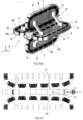
- the apparatus 1 includes two track frames 2, 3 that mount respective sets 4, 5 of die elements 6.
- the die elements 6 have any suitable profile determined by the profile desired to be formed.
- respective male and female die sets suitable for forming a channel or a top-hat profile are shown.
- Each die element 6 is mounted on a chain link 7 respectively connected to the adjacent chain link 7 by a pin 8 in a conventional manner to form a roller chain.
- the track frames 2, 3 define respective endless paths or tracks around which the links 7 travel.
- Each of the paths has a forming portion 9, 10 in which the die elements 6 of each set are opposed to define a forming space 11.
- the forming portions 9, 10 are configured so that the dimensions of the space 11 between the forming portions reduce along its length. In this way transverse forces are simultaneously applied to a section passing through the forming portion.
- the die elements 6 move with the material synchronisely and the distance between the sets of elements 6 gradually reduces.
- Figure 3 shows an embodiment of the invention for forming the profile of a deformable hollow section from a pre-formed tubular section.
- the apparatus 1 includes four track frame elements 2, 2a, 3, 3a arranged in opposed pairs. Each track frame element mounts respective sets 4, 4a, 5, 5a of die elements 6.
- the die elements 6 have any suitable profile determined by the profile desired to be formed in the material.
- Each die element 6 is mounted on a chain link 7 respectively connected to the adjacent chain link 7 by a pin 8 in a conventional manner to form a roller chain.
- the track frames 2, 2a, 3, 3a define respective endless paths around which the links 7 travel.
- Each of the paths has a forming portion 9, 9a, 10, 10a in which the die elements 6 associated with each pair of track frames are opposed to define a forming space 11.
- the forming portions 9, 9a, 10, 10a are configured so that the dimensions of the space 11 between the forming portions reduce along its length. In this way transverse forces are simultaneously applied to a section passing through the forming portion. This can be visualised as the section to be formed being forced through a progressively smaller aperture as it progresses through the forming portion.
- Figures 4(a) to 4(c) show three different configurations of die elements 6 profiles at respective locations along the formed portion 10.
- Figure 4(a) shows a configuration applicable to the embodiment shown in Figures 1 and 2 for forming the profile of a deformable sheet material m.
- the die sets are made up of respective male and female opposed dies. As the dies move along the forming portions 9, 10 the distance between them decreases to reduce the forming space in the direction from right to left. This progressively forms the material to a desired profile.
- Figures 4(b) and 4(c) show a configuration of die sets used in the embodiment generally described in relation to Figure 3 .
- Figure 4(b) four die sets arranged in opposed pairs are used to form a circular section h into a square section as the dies move together along the forming space.
- Figure 4(c) shows an arrangement in which three sets of dies displaced at 120° to form a circular section h to a triangular profile.
- Figure 5 shows an alternative to the apparatus shown in Figures 1 and 2 .
- one lower set 12 of die elements 6 have the profile of the final die profile.
- Three upper sets 6 of progressive shaped complimentary die elements upon track frames 2 are sequentially positioned.
- this provides forming portions 9, 10 at three spaced apart locations.
- the forming portions of the tracks are configured to progressively reduce the dimensions to the space 11 between the dies.
- the material m to be formed progressively proceeds from right to left as shown in the drawings and is formed to the desired profile by the sequential operation of the die sets.
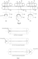
- Figures 6(a) to 6(c) show some exemplary ways in which the apparatus can operate.
- the system is provided with driving sprockets which drive the two sets of die elements in phase so as to draw a section through the forming portion.
- a separate set of driving rolls is provided to propel this section through the forming portion.
- Figure 6(c) shows a similar configuration in which a separate set of driving rolls are used to push a section through the forming portion.
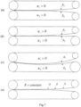
- Figures 7(a) to 7(d) show some of the possible configurations of the track in the forming portion of the apparatus.
- each of the opposed forming portions has a large radius and the centre of the radii are respectively on the opposite sides of the forming space.
- Figure 7(b) shows configuration in which one of the forming portions has a large radius and another has an infinite radius or in other words is flat.
- Figure 7(c) shows a configuration in which the centres of the radii are both on one side of the forming space and large radii are used for the respective forming portions to provide converging paths between the opposed dies.
- Figure 7(d) shows a configuration in which the radii of the forming portion is not constant to provide a converging track between the opposed dies.
- Figure 8(a) schematically shows the relationship between the maximum gap between adjacent dies on the chain and the radius of the portion of the track.
- the pitch to radius ratio is large and preferably over 1:500.
- the maximum gap between the adjacent dies is approximately the product of the height and the length divided by the radius of the track.
- the distance s the chord height between cord c extending through the mid point of the upper die surface and the adjacent die corners is a measure of the relative angle between the die blocks. It is approximately equal to the square of the length of each die divided by quad the radius. It will be apparent that larger gaps may occur in portions of the track other than the forming portion without in any way affecting the operation of the apparatus.
- Figures 9(a) to 9(c) schematically shows some of the profiles that can be formed from a circular section using the apparatus of this invention.
- Figure 9(a) shows a triangular profile.
- Figure 9(b) shows a rectangular profile and
- Figure 9(c) a stepped profile. It will be apparent however that appropriate selection of die shapes can produce a wide range of profiles.
- Figure 10 shows a modified form of the die sets suitable for use in the invention as described in Figures 1 and 2 .
- the die elements 6 are not uniform but form a taper. By arranging these dies in sections on corresponding parts of the respective tracks a profile having a longitudinal taper or other desired non linear form can be formed.
- Embodiments of this invention can be in the form of standalone equipment lined before or after a forming process such as roll forming to process auxiliary operations such as blanking, punching, dooming, coining, shearing and the like. Because the forming dies' velocity is so close the strip's velocity, the auxiliary operation is processed continuously without the interference with the strip that occurs in the rotary punching or dooming.
- a forming process such as roll forming
- auxiliary operations such as blanking, punching, dooming, coining, shearing and the like.
- Figures 11(a) and 11(b) schematically show die configurations for performing punching and dooming respectively.
- opposed dies corresponding shaped to perform the operation more through a forming function in which the dimension of the forming space reduce along the length of the forming portion.
- one part of the die elements are rigid to ensure the profile to be formed but the another can be elastically deformable such as using polyurethane.
- the deformable die elements can provide adequate compressing force to the material to be formed and/or compensate the variation of material properties and thickness.
- Embodiments of the invention can also be used to form a part having limited length that requires multiple passes to form.
- the forming dies for each pass (for example, 8 passes as shown) are arranged in one set and the motions of the sets are synchronised.
- the blank is fed into the former a corresponding number of times to achieve the final profile in one machine.
- This arrangement is to save the capital and space, and another is this type former can be placed beside an assembly line for multi component product and after forming a workpart on-site, the part can be assembled to the product directly.
- a guiding system can be a separate apparatus or embedded in the die-blocks.
- using magnetic die blocks in one die set can sufficiently control the steel strip moving straight forward.
- Other method such as guide plates assembled on the die-blocks may also be applied to guide the strip going straight.
Landscapes
- Engineering & Computer Science (AREA)
- Mechanical Engineering (AREA)
- Bending Of Plates, Rods, And Pipes (AREA)
- Shaping Metal By Deep-Drawing, Or The Like (AREA)
- Moulds For Moulding Plastics Or The Like (AREA)
- Press Drives And Press Lines (AREA)
- Shaping Of Tube Ends By Bending Or Straightening (AREA)
Applications Claiming Priority (2)
| Application Number | Priority Date | Filing Date | Title |
|---|---|---|---|
| AU2010902659A AU2010902659A0 (en) | 2010-06-18 | Method and apparatus for forming the profile of deformable materials and deformable tubular sections | |
| PCT/AU2011/000744 WO2011156873A1 (en) | 2010-06-18 | 2011-06-20 | Method and apparatus for forming the profile of deformable materials and deformable tubular sections |
Publications (3)
| Publication Number | Publication Date |
|---|---|
| EP2582474A1 EP2582474A1 (en) | 2013-04-24 |
| EP2582474A4 EP2582474A4 (en) | 2017-11-15 |
| EP2582474B1 true EP2582474B1 (en) | 2024-12-25 |
Family
ID=45347597
Family Applications (1)
| Application Number | Title | Priority Date | Filing Date |
|---|---|---|---|
| EP11794966.9A Active EP2582474B1 (en) | 2010-06-18 | 2011-06-20 | Method and apparatus for forming the profile of deformable materials |
Country Status (6)
| Country | Link |
|---|---|
| US (1) | US9676018B2 (enExample) |
| EP (1) | EP2582474B1 (enExample) |
| JP (1) | JP5860041B2 (enExample) |
| CN (1) | CN103313806B (enExample) |
| AU (1) | AU2011267770B2 (enExample) |
| WO (1) | WO2011156873A1 (enExample) |
Families Citing this family (12)
| Publication number | Priority date | Publication date | Assignee | Title |
|---|---|---|---|---|
| CN103418657B (zh) * | 2013-08-28 | 2015-09-16 | 北京科技大学 | 组合模具板金属连续冲压成形工艺及成形设备 |
| JP2015085373A (ja) * | 2013-11-01 | 2015-05-07 | カルソニックカンセイ株式会社 | 回転金型装置 |
| EP3110619B1 (en) * | 2014-02-25 | 2019-04-10 | Sns Unicorp Pty. Ltd. | Method and apparatus for forming profiled articles |
| WO2016104718A1 (ja) * | 2014-12-26 | 2016-06-30 | 株式会社中田製作所 | 管の成形方法及び装置 |
| CN104826917B (zh) * | 2015-05-19 | 2017-02-01 | 河南机电高等专科学校 | 双履带凸轮连续冲压模具 |
| JP6844255B2 (ja) * | 2016-12-28 | 2021-03-17 | 日本製鉄株式会社 | キャラクターラインを有するパネルの製造装置および製造方法 |
| US10907626B2 (en) | 2017-02-16 | 2021-02-02 | Biosense Webster (Israel) Ltd. | Peristaltic pump with reduced triboelectric effects |
| US11698059B2 (en) | 2018-12-29 | 2023-07-11 | Biosense Webster (Israel) Ltd. | Disposable dual-action reciprocating pump assembly |
| US11795941B2 (en) | 2018-12-29 | 2023-10-24 | Biosense Webster (Israel) Ltd. | Using silicone o-rings in dual action irrigation pump |
| CN113772931B (zh) * | 2021-09-10 | 2022-09-09 | 武汉华星光电半导体显示技术有限公司 | 曲面显示面板的成型设备及其成型方法、曲面显示面板 |
| BE1032051B1 (nl) | 2023-10-12 | 2025-05-13 | Joris Ide Nv | Inrichting met vergrendelmechanisme en werkwijze voor produceren van een niet-vlak geïsoleerd bekledingspaneel en erdoor verkregen geïsoleerd bekledingspaneel |
| WO2025081222A1 (en) * | 2023-10-16 | 2025-04-24 | The University Of Queensland | A forming apparatus and method |
Citations (1)
| Publication number | Priority date | Publication date | Assignee | Title |
|---|---|---|---|---|
| WO2009110372A1 (ja) * | 2008-03-03 | 2009-09-11 | 株式会社中田製作所 | 成形装置とそのシュー及び成形方法 |
Family Cites Families (19)
| Publication number | Priority date | Publication date | Assignee | Title |
|---|---|---|---|---|
| FR350599A (fr) * | 1904-01-20 | 1905-06-17 | Edwin Ebert Arnold | Perfectionnements pour le réglage automatique des moteurs à explosion |
| US1980308A (en) * | 1929-05-23 | 1934-11-13 | Youngstown Sheet And Tube Co | Method and apparatus for forming material |
| US2642280A (en) * | 1945-10-25 | 1953-06-16 | Gustaf L Fisk | Apparatus for cold reducing metal bars |
| US2569266A (en) * | 1946-10-25 | 1951-09-25 | Nat Steel Corp | Rib curving machine |
| US3059319A (en) * | 1960-03-31 | 1962-10-23 | Robert H Hart | Method for making flexible tubular members |
| CH469516A (it) * | 1967-03-29 | 1969-03-15 | Properzi Ilario | Laminatoio per la laminazione continua di barre, fili e profilati vari metallici |
| US3568245A (en) * | 1967-07-24 | 1971-03-09 | Raimund Jetzer | Apparatus for making composition panels |
| JPS5129360A (en) * | 1974-09-05 | 1976-03-12 | Sumikin Kozai Kogyo Kk | Renzoku uo seikeihoho |
| US4000636A (en) * | 1975-05-01 | 1977-01-04 | Vladimir Nikolaevich Shubin | Pipe bending machine |
| JPS5219163A (en) * | 1975-08-07 | 1977-02-14 | Reikan Rooru Seikei Kikai Kenk | Press mechanism |
| US4429559A (en) * | 1982-01-26 | 1984-02-07 | Depuglia Gaston D | Strip processing apparatus |
| US4917540A (en) * | 1984-08-31 | 1990-04-17 | Santa Fe International Corporation | Pipeline laying system and vessel with pipeline straightening and tensioning device |
| JPH0649760A (ja) * | 1992-07-28 | 1994-02-22 | Iwamoto Seisakusho:Kk | ラップの熱接着による立体的形状の成形方法及びその装置 |
| FR2755639B1 (fr) * | 1996-11-12 | 1999-01-29 | Onduline Sa | Machine pour reprofiler des materiaux ondules |
| JP2004154793A (ja) * | 2002-11-05 | 2004-06-03 | Denso Corp | ロール成形方法およびその装置 |
| DE102005022244B4 (de) * | 2005-05-13 | 2007-07-19 | Eroform Edelstahl Gmbh | Führungs- und Verformungssystem, dessen Verwendung sowie Verfahren zur Herstellung von geschweißten Rohren |
| JP2008030112A (ja) * | 2006-07-28 | 2008-02-14 | Goro Igarashi | 薄鋼板波板の曲げ加工 |
| KR20100049510A (ko) * | 2007-06-01 | 2010-05-12 | 더 유니버서티 어브 퀸슬랜드 | 변형성 물질을 압축 성형하기 위한 조립체 및 방법 |
| US8161786B2 (en) * | 2008-04-15 | 2012-04-24 | Glen Stapleton | Apparatus for feeding and turning tube products into a pilger mill machine |
-
2011
- 2011-06-20 US US13/805,084 patent/US9676018B2/en active Active
- 2011-06-20 EP EP11794966.9A patent/EP2582474B1/en active Active
- 2011-06-20 CN CN201180037732.2A patent/CN103313806B/zh active Active
- 2011-06-20 WO PCT/AU2011/000744 patent/WO2011156873A1/en not_active Ceased
- 2011-06-20 AU AU2011267770A patent/AU2011267770B2/en active Active
- 2011-06-20 JP JP2013514499A patent/JP5860041B2/ja active Active
Patent Citations (1)
| Publication number | Priority date | Publication date | Assignee | Title |
|---|---|---|---|---|
| WO2009110372A1 (ja) * | 2008-03-03 | 2009-09-11 | 株式会社中田製作所 | 成形装置とそのシュー及び成形方法 |
Also Published As
| Publication number | Publication date |
|---|---|
| EP2582474A4 (en) | 2017-11-15 |
| AU2011267770A1 (en) | 2013-01-10 |
| JP5860041B2 (ja) | 2016-02-16 |
| US9676018B2 (en) | 2017-06-13 |
| CN103313806A (zh) | 2013-09-18 |
| US20130174630A1 (en) | 2013-07-11 |
| AU2011267770B2 (en) | 2017-02-02 |
| CN103313806B (zh) | 2016-08-17 |
| WO2011156873A1 (en) | 2011-12-22 |
| EP2582474A1 (en) | 2013-04-24 |
| JP2013533806A (ja) | 2013-08-29 |
Similar Documents
| Publication | Publication Date | Title |
|---|---|---|
| EP2582474B1 (en) | Method and apparatus for forming the profile of deformable materials | |
| US10414107B2 (en) | Method and material efficient tooling for continuous compression molding | |
| US9174258B2 (en) | Apparatus and process for forming profiles with a variable height by means of cold rolling | |
| CN101965260A (zh) | 成形装置、该成形装置的模板以及成形方法 | |
| MX2011003554A (es) | Sistema para formacion con rollos frios de perfiles que tienen secciones transversales variables. | |
| US5237846A (en) | Method and apparatus for forming metal roll-formed parts | |
| EP1585608B1 (en) | Method and apparatus for in-situ leveling of progressively formed sheet metal | |
| ITBO20100083A1 (it) | Metodo e apparecchiatura per raddrizzare tondini di ferro e simili | |
| KR100778763B1 (ko) | 한 개의 공전롤을 갖는 인발형 연속 전단변형장치 | |
| CN108080499A (zh) | 无级变速器用金属元件的制造方法 | |
| DE102015210259B4 (de) | Verfahren zum Herstellen von Schlitzrohren aus Blechtafeln | |
| CN114570784A (zh) | 一种大口径不锈钢管的成型装置 | |
| US5176019A (en) | Forming of metal structural members | |
| US5272899A (en) | Method and apparatus for hot roll forming inside U-shaped channel section | |
| KR20010068450A (ko) | 이형재 스트립의 제조방법 | |
| GB2095595A (en) | Sheet material and method of producing formations in continuously processed material | |
| DE102005031437A1 (de) | Vorrichtung zum Umformen eines bandförmigen Werkstückes | |
| JPH09108707A (ja) | T形鋼の製造装置 | |
| EP3110619B1 (en) | Method and apparatus for forming profiled articles | |
| EP2208555B1 (de) | Walzverfahren und Walzvorrichtung zum Herstellen eines Metallbands mit einer über seine Breite variierenden Dicke | |
| US4099662A (en) | Method and apparatus for producing welded steel tubes having large square cross section | |
| RU2341347C2 (ru) | Способ изготовления шевронного заполнителя и устройство для его осуществления | |
| KR200186267Y1 (ko) | 이형재 스트립의 제조장치 | |
| AU2001285613B2 (en) | Method and apparatus for the continuous press-forming of wide panels | |
| WO2002022285A1 (en) | Method and apparatus for the continuous press-forming of wide panels |
Legal Events
| Date | Code | Title | Description |
|---|---|---|---|
| PUAI | Public reference made under article 153(3) epc to a published international application that has entered the european phase |
Free format text: ORIGINAL CODE: 0009012 |
|
| 17P | Request for examination filed |
Effective date: 20121218 |
|
| AK | Designated contracting states |
Kind code of ref document: A1 Designated state(s): AL AT BE BG CH CY CZ DE DK EE ES FI FR GB GR HR HU IE IS IT LI LT LU LV MC MK MT NL NO PL PT RO RS SE SI SK SM TR |
|
| DAX | Request for extension of the european patent (deleted) | ||
| RA4 | Supplementary search report drawn up and despatched (corrected) |
Effective date: 20171018 |
|
| RIC1 | Information provided on ipc code assigned before grant |
Ipc: B21C 37/15 20060101ALI20171012BHEP Ipc: B21D 5/12 20060101AFI20171012BHEP Ipc: B30B 5/06 20060101ALI20171012BHEP Ipc: B21D 22/08 20060101ALI20171012BHEP Ipc: B21D 7/08 20060101ALI20171012BHEP |
|
| STAA | Information on the status of an ep patent application or granted ep patent |
Free format text: STATUS: EXAMINATION IS IN PROGRESS |
|
| 17Q | First examination report despatched |
Effective date: 20200417 |
|
| APBK | Appeal reference recorded |
Free format text: ORIGINAL CODE: EPIDOSNREFNE |
|
| APBN | Date of receipt of notice of appeal recorded |
Free format text: ORIGINAL CODE: EPIDOSNNOA2E |
|
| APBR | Date of receipt of statement of grounds of appeal recorded |
Free format text: ORIGINAL CODE: EPIDOSNNOA3E |
|
| APAF | Appeal reference modified |
Free format text: ORIGINAL CODE: EPIDOSCREFNE |
|
| APAF | Appeal reference modified |
Free format text: ORIGINAL CODE: EPIDOSCREFNE |
|
| APBX | Invitation to file observations in appeal sent |
Free format text: ORIGINAL CODE: EPIDOSNOBA2E |
|
| APBZ | Receipt of observations in appeal recorded |
Free format text: ORIGINAL CODE: EPIDOSNOBA4E |
|
| APBT | Appeal procedure closed |
Free format text: ORIGINAL CODE: EPIDOSNNOA9E |
|
| GRAP | Despatch of communication of intention to grant a patent |
Free format text: ORIGINAL CODE: EPIDOSNIGR1 |
|
| STAA | Information on the status of an ep patent application or granted ep patent |
Free format text: STATUS: GRANT OF PATENT IS INTENDED |
|
| INTG | Intention to grant announced |
Effective date: 20240718 |
|
| GRAS | Grant fee paid |
Free format text: ORIGINAL CODE: EPIDOSNIGR3 |
|
| GRAA | (expected) grant |
Free format text: ORIGINAL CODE: 0009210 |
|
| STAA | Information on the status of an ep patent application or granted ep patent |
Free format text: STATUS: THE PATENT HAS BEEN GRANTED |
|
| AK | Designated contracting states |
Kind code of ref document: B1 Designated state(s): AL AT BE BG CH CY CZ DE DK EE ES FI FR GB GR HR HU IE IS IT LI LT LU LV MC MK MT NL NO PL PT RO RS SE SI SK SM TR |
|
| REG | Reference to a national code |
Ref country code: GB Ref legal event code: FG4D |
|
| REG | Reference to a national code |
Ref country code: CH Ref legal event code: EP |
|
| REG | Reference to a national code |
Ref country code: DE Ref legal event code: R096 Ref document number: 602011075174 Country of ref document: DE |
|
| REG | Reference to a national code |
Ref country code: IE Ref legal event code: FG4D |
|
| REG | Reference to a national code |
Ref country code: LT Ref legal event code: MG9D |
|
| PG25 | Lapsed in a contracting state [announced via postgrant information from national office to epo] |
Ref country code: FI Free format text: LAPSE BECAUSE OF FAILURE TO SUBMIT A TRANSLATION OF THE DESCRIPTION OR TO PAY THE FEE WITHIN THE PRESCRIBED TIME-LIMIT Effective date: 20241225 |
|
| P01 | Opt-out of the competence of the unified patent court (upc) registered |
Free format text: CASE NUMBER: APP_11268/2025 Effective date: 20250307 |
|
| PG25 | Lapsed in a contracting state [announced via postgrant information from national office to epo] |
Ref country code: BG Free format text: LAPSE BECAUSE OF FAILURE TO SUBMIT A TRANSLATION OF THE DESCRIPTION OR TO PAY THE FEE WITHIN THE PRESCRIBED TIME-LIMIT Effective date: 20241225 |
|
| PG25 | Lapsed in a contracting state [announced via postgrant information from national office to epo] |
Ref country code: NO Free format text: LAPSE BECAUSE OF FAILURE TO SUBMIT A TRANSLATION OF THE DESCRIPTION OR TO PAY THE FEE WITHIN THE PRESCRIBED TIME-LIMIT Effective date: 20250325 |
|
| PG25 | Lapsed in a contracting state [announced via postgrant information from national office to epo] |
Ref country code: GR Free format text: LAPSE BECAUSE OF FAILURE TO SUBMIT A TRANSLATION OF THE DESCRIPTION OR TO PAY THE FEE WITHIN THE PRESCRIBED TIME-LIMIT Effective date: 20250326 Ref country code: LV Free format text: LAPSE BECAUSE OF FAILURE TO SUBMIT A TRANSLATION OF THE DESCRIPTION OR TO PAY THE FEE WITHIN THE PRESCRIBED TIME-LIMIT Effective date: 20241225 |
|
| PG25 | Lapsed in a contracting state [announced via postgrant information from national office to epo] |
Ref country code: RS Free format text: LAPSE BECAUSE OF FAILURE TO SUBMIT A TRANSLATION OF THE DESCRIPTION OR TO PAY THE FEE WITHIN THE PRESCRIBED TIME-LIMIT Effective date: 20250325 |
|
| REG | Reference to a national code |
Ref country code: NL Ref legal event code: MP Effective date: 20241225 |
|
| PG25 | Lapsed in a contracting state [announced via postgrant information from national office to epo] |
Ref country code: NL Free format text: LAPSE BECAUSE OF FAILURE TO SUBMIT A TRANSLATION OF THE DESCRIPTION OR TO PAY THE FEE WITHIN THE PRESCRIBED TIME-LIMIT Effective date: 20241225 |
|
| REG | Reference to a national code |
Ref country code: AT Ref legal event code: MK05 Ref document number: 1753752 Country of ref document: AT Kind code of ref document: T Effective date: 20241225 |
|
| PG25 | Lapsed in a contracting state [announced via postgrant information from national office to epo] |
Ref country code: SM Free format text: LAPSE BECAUSE OF FAILURE TO SUBMIT A TRANSLATION OF THE DESCRIPTION OR TO PAY THE FEE WITHIN THE PRESCRIBED TIME-LIMIT Effective date: 20241225 |
|
| PG25 | Lapsed in a contracting state [announced via postgrant information from national office to epo] |
Ref country code: PL Free format text: LAPSE BECAUSE OF FAILURE TO SUBMIT A TRANSLATION OF THE DESCRIPTION OR TO PAY THE FEE WITHIN THE PRESCRIBED TIME-LIMIT Effective date: 20241225 |
|
| PGFP | Annual fee paid to national office [announced via postgrant information from national office to epo] |
Ref country code: DE Payment date: 20250618 Year of fee payment: 15 |
|
| PG25 | Lapsed in a contracting state [announced via postgrant information from national office to epo] |
Ref country code: ES Free format text: LAPSE BECAUSE OF FAILURE TO SUBMIT A TRANSLATION OF THE DESCRIPTION OR TO PAY THE FEE WITHIN THE PRESCRIBED TIME-LIMIT Effective date: 20241225 |
|
| PG25 | Lapsed in a contracting state [announced via postgrant information from national office to epo] |
Ref country code: IS Free format text: LAPSE BECAUSE OF FAILURE TO SUBMIT A TRANSLATION OF THE DESCRIPTION OR TO PAY THE FEE WITHIN THE PRESCRIBED TIME-LIMIT Effective date: 20250425 |
|
| PG25 | Lapsed in a contracting state [announced via postgrant information from national office to epo] |
Ref country code: PT Free format text: LAPSE BECAUSE OF FAILURE TO SUBMIT A TRANSLATION OF THE DESCRIPTION OR TO PAY THE FEE WITHIN THE PRESCRIBED TIME-LIMIT Effective date: 20250428 |
|
| PG25 | Lapsed in a contracting state [announced via postgrant information from national office to epo] |
Ref country code: EE Free format text: LAPSE BECAUSE OF FAILURE TO SUBMIT A TRANSLATION OF THE DESCRIPTION OR TO PAY THE FEE WITHIN THE PRESCRIBED TIME-LIMIT Effective date: 20241225 |
|
| PGFP | Annual fee paid to national office [announced via postgrant information from national office to epo] |
Ref country code: FR Payment date: 20250624 Year of fee payment: 15 |
|
| PG25 | Lapsed in a contracting state [announced via postgrant information from national office to epo] |
Ref country code: RO Free format text: LAPSE BECAUSE OF FAILURE TO SUBMIT A TRANSLATION OF THE DESCRIPTION OR TO PAY THE FEE WITHIN THE PRESCRIBED TIME-LIMIT Effective date: 20241225 Ref country code: AT Free format text: LAPSE BECAUSE OF FAILURE TO SUBMIT A TRANSLATION OF THE DESCRIPTION OR TO PAY THE FEE WITHIN THE PRESCRIBED TIME-LIMIT Effective date: 20241225 |
|
| PG25 | Lapsed in a contracting state [announced via postgrant information from national office to epo] |
Ref country code: SK Free format text: LAPSE BECAUSE OF FAILURE TO SUBMIT A TRANSLATION OF THE DESCRIPTION OR TO PAY THE FEE WITHIN THE PRESCRIBED TIME-LIMIT Effective date: 20241225 |
|
| PG25 | Lapsed in a contracting state [announced via postgrant information from national office to epo] |
Ref country code: CZ Free format text: LAPSE BECAUSE OF FAILURE TO SUBMIT A TRANSLATION OF THE DESCRIPTION OR TO PAY THE FEE WITHIN THE PRESCRIBED TIME-LIMIT Effective date: 20241225 |
|
| PG25 | Lapsed in a contracting state [announced via postgrant information from national office to epo] |
Ref country code: IT Free format text: LAPSE BECAUSE OF FAILURE TO SUBMIT A TRANSLATION OF THE DESCRIPTION OR TO PAY THE FEE WITHIN THE PRESCRIBED TIME-LIMIT Effective date: 20241225 |
|
| PG25 | Lapsed in a contracting state [announced via postgrant information from national office to epo] |
Ref country code: SE Free format text: LAPSE BECAUSE OF FAILURE TO SUBMIT A TRANSLATION OF THE DESCRIPTION OR TO PAY THE FEE WITHIN THE PRESCRIBED TIME-LIMIT Effective date: 20241225 |
|
| REG | Reference to a national code |
Ref country code: DE Ref legal event code: R097 Ref document number: 602011075174 Country of ref document: DE |
|
| PG25 | Lapsed in a contracting state [announced via postgrant information from national office to epo] |
Ref country code: DK Free format text: LAPSE BECAUSE OF FAILURE TO SUBMIT A TRANSLATION OF THE DESCRIPTION OR TO PAY THE FEE WITHIN THE PRESCRIBED TIME-LIMIT Effective date: 20241225 |
|
| PLBE | No opposition filed within time limit |
Free format text: ORIGINAL CODE: 0009261 |
|
| STAA | Information on the status of an ep patent application or granted ep patent |
Free format text: STATUS: NO OPPOSITION FILED WITHIN TIME LIMIT |
|
| REG | Reference to a national code |
Ref country code: CH Ref legal event code: L10 Free format text: ST27 STATUS EVENT CODE: U-0-0-L10-L00 (AS PROVIDED BY THE NATIONAL OFFICE) Effective date: 20251105 |
|
| 26N | No opposition filed |
Effective date: 20250926 |
|
| REG | Reference to a national code |
Ref country code: CH Ref legal event code: H13 Free format text: ST27 STATUS EVENT CODE: U-0-0-H10-H13 (AS PROVIDED BY THE NATIONAL OFFICE) Effective date: 20260127 |
|
| PG25 | Lapsed in a contracting state [announced via postgrant information from national office to epo] |
Ref country code: MC Free format text: LAPSE BECAUSE OF FAILURE TO SUBMIT A TRANSLATION OF THE DESCRIPTION OR TO PAY THE FEE WITHIN THE PRESCRIBED TIME-LIMIT Effective date: 20241225 |
|
| PG25 | Lapsed in a contracting state [announced via postgrant information from national office to epo] |
Ref country code: LU Free format text: LAPSE BECAUSE OF NON-PAYMENT OF DUE FEES Effective date: 20250620 |
|
| GBPC | Gb: european patent ceased through non-payment of renewal fee |
Effective date: 20250620 |
|
| REG | Reference to a national code |
Ref country code: BE Ref legal event code: MM Effective date: 20250630 |
|
| PG25 | Lapsed in a contracting state [announced via postgrant information from national office to epo] |
Ref country code: GB Free format text: LAPSE BECAUSE OF NON-PAYMENT OF DUE FEES Effective date: 20250620 |
|
| PG25 | Lapsed in a contracting state [announced via postgrant information from national office to epo] |
Ref country code: IE Free format text: LAPSE BECAUSE OF NON-PAYMENT OF DUE FEES Effective date: 20250620 |
|
| PG25 | Lapsed in a contracting state [announced via postgrant information from national office to epo] |
Ref country code: HR Free format text: LAPSE BECAUSE OF FAILURE TO SUBMIT A TRANSLATION OF THE DESCRIPTION OR TO PAY THE FEE WITHIN THE PRESCRIBED TIME-LIMIT Effective date: 20241225 |
|
| PG25 | Lapsed in a contracting state [announced via postgrant information from national office to epo] |
Ref country code: BE Free format text: LAPSE BECAUSE OF NON-PAYMENT OF DUE FEES Effective date: 20250630 |
|
| PG25 | Lapsed in a contracting state [announced via postgrant information from national office to epo] |
Ref country code: CH Free format text: LAPSE BECAUSE OF NON-PAYMENT OF DUE FEES Effective date: 20250630 |