EP2582439B1 - Verfahren zur Herstellung eines Einlaufkanals, und ein nachgerüsteter Einlaufkanal - Google Patents
Verfahren zur Herstellung eines Einlaufkanals, und ein nachgerüsteter Einlaufkanal Download PDFInfo
- Publication number
- EP2582439B1 EP2582439B1 EP11796137.5A EP11796137A EP2582439B1 EP 2582439 B1 EP2582439 B1 EP 2582439B1 EP 11796137 A EP11796137 A EP 11796137A EP 2582439 B1 EP2582439 B1 EP 2582439B1
- Authority
- EP
- European Patent Office
- Prior art keywords
- channel
- baffle
- flow
- input channel
- depth
- Prior art date
- Legal status (The legal status is an assumption and is not a legal conclusion. Google has not performed a legal analysis and makes no representation as to the accuracy of the status listed.)
- Active
Links
Images






Classifications
-
- B—PERFORMING OPERATIONS; TRANSPORTING
- B01—PHYSICAL OR CHEMICAL PROCESSES OR APPARATUS IN GENERAL
- B01D—SEPARATION
- B01D21/00—Separation of suspended solid particles from liquids by sedimentation
- B01D21/24—Feed or discharge mechanisms for settling tanks
- B01D21/2405—Feed mechanisms for settling tanks
- B01D21/2411—Feed mechanisms for settling tanks having a tangential inlet
-
- B—PERFORMING OPERATIONS; TRANSPORTING
- B01—PHYSICAL OR CHEMICAL PROCESSES OR APPARATUS IN GENERAL
- B01D—SEPARATION
- B01D21/00—Separation of suspended solid particles from liquids by sedimentation
- B01D21/26—Separation of sediment aided by centrifugal force or centripetal force
-
- B—PERFORMING OPERATIONS; TRANSPORTING
- B04—CENTRIFUGAL APPARATUS OR MACHINES FOR CARRYING-OUT PHYSICAL OR CHEMICAL PROCESSES
- B04C—APPARATUS USING FREE VORTEX FLOW, e.g. CYCLONES
- B04C3/00—Apparatus in which the axial direction of the vortex flow following a screw-thread type line remains unchanged ; Devices in which one of the two discharge ducts returns centrally through the vortex chamber, a reverse-flow vortex being prevented by bulkheads in the central discharge duct
- B04C3/06—Construction of inlets or outlets to the vortex chamber
-
- Y—GENERAL TAGGING OF NEW TECHNOLOGICAL DEVELOPMENTS; GENERAL TAGGING OF CROSS-SECTIONAL TECHNOLOGIES SPANNING OVER SEVERAL SECTIONS OF THE IPC; TECHNICAL SUBJECTS COVERED BY FORMER USPC CROSS-REFERENCE ART COLLECTIONS [XRACs] AND DIGESTS
- Y10—TECHNICAL SUBJECTS COVERED BY FORMER USPC
- Y10T—TECHNICAL SUBJECTS COVERED BY FORMER US CLASSIFICATION
- Y10T137/00—Fluid handling
- Y10T137/794—With means for separating solid material from the fluid
- Y10T137/8013—Sediment chamber
-
- Y—GENERAL TAGGING OF NEW TECHNOLOGICAL DEVELOPMENTS; GENERAL TAGGING OF CROSS-SECTIONAL TECHNOLOGIES SPANNING OVER SEVERAL SECTIONS OF THE IPC; TECHNICAL SUBJECTS COVERED BY FORMER USPC CROSS-REFERENCE ART COLLECTIONS [XRACs] AND DIGESTS
- Y10—TECHNICAL SUBJECTS COVERED BY FORMER USPC
- Y10T—TECHNICAL SUBJECTS COVERED BY FORMER US CLASSIFICATION
- Y10T29/00—Metal working
- Y10T29/49—Method of mechanical manufacture
-
- Y—GENERAL TAGGING OF NEW TECHNOLOGICAL DEVELOPMENTS; GENERAL TAGGING OF CROSS-SECTIONAL TECHNOLOGIES SPANNING OVER SEVERAL SECTIONS OF THE IPC; TECHNICAL SUBJECTS COVERED BY FORMER USPC CROSS-REFERENCE ART COLLECTIONS [XRACs] AND DIGESTS
- Y10—TECHNICAL SUBJECTS COVERED BY FORMER USPC
- Y10T—TECHNICAL SUBJECTS COVERED BY FORMER US CLASSIFICATION
- Y10T29/00—Metal working
- Y10T29/49—Method of mechanical manufacture
- Y10T29/494—Fluidic or fluid actuated device making
Definitions
- This invention relates to a flow channel, and more particularly to an input flow channel for the flow of waste water into a grit removal system of a waste treatment system.
- Grit removal systems such as grit extractors or grit traps have been used in many waste water treatment systems to remove grit from the waste water prior to passing the water onto further process and collect the grit to transfer to a recovery device of the system.
- Grit removal systems operate according to a variety of methods. For example, some facilities hold grit-laden water in oversized storage tanks and allow the grit to settle out of the water over time. Other facilities use air induced flow patterns or forced vortex methods to separate grit from the water.
- one advantageous grit removal system includes an apparatus which includes flumes for injecting and extracting liquid (e.g., waste water) tangentially relative to a round chamber, thus creating a forced vortex in the chamber.
- liquid e.g., waste water
- the grit-laden waste water flows through a channel from an upstream portion of the waste water system and then into the round chamber of the grit removal system. Flow velocity into the round chamber facilitates operation of the grit removal system by creating a circular flow stream which causes the grit to settle near the bottom center of the round chamber.
- the grit in the input waste water is thus removed from the liquid stream and collected in the storage chamber for relatively easy removal.
- Such an apparatus is disclosed in U.S. Patent No. 6,811,697 B2 .
- U.S. Patent No. 4,767,532 similarly discloses an apparatus for removing grit in which a grit storage chamber is provided beneath the center of the round chamber of the grit removal system. Liquid flow in the round chamber causes grit particles to settle toward the chamber floor, where they are urged radially inwardly so as to drop through an opening into a grit storage chamber.
- Excellent grit removal systems are available, for example, from Smith & Loveless, Inc. of 14040 Santa Fe Trail Drive, Lenexa, Kansas 66215-1284 , including its PISTA® grit removal system which has a flat bottomed grit chamber and operates on the forced vortex principal.
- the flow of waste water into the channel to the round chamber may significantly vary.
- grit (including sand) in waste water does not float or flow consistently, if the velocity of flow is not sufficiently high the grit and sand may not be maintained in suspension and pushed down the channel, in which case it will settle to the bottom of a channel before reaching the grit removal system where it can be properly removed from the system.
- the flow rate of waste water may vary widely during a given day, as water use in the community and industry in the area, even if predictable, will seldom be uniform (e.g., a factory may discharge large amounts of waste water at different times of the day, and/or individual users may generate more load in the morning than at midnight).
- water usage may vary widely over the design life of a waste water system. For example, systems are often built to be able to handle a maximum load which may not be anticipated to occur for many years (e.g., when a new community is built out). Until that build out occurs, flow rates could be significantly less than designed for. Similarly, waste water systems built years ago to handle an anticipated maximum load may now find that the maximum load anticipated years ago will never occur ( e . g ., because planned buildings were never built, and/or home and industry usage became more efficient than was anticipated when the waste system was built).
- the input channels are generally formed of concrete with vertical side walls and flat bottoms, and where the flow velocity through such a channel (which is based on the actual flow rate of waste water at a given facility) has been found to be of an insufficient volume, concrete blocks or a vertical steel plate (fastened in place) have been placed in the channel to create a different vertical side wall which narrows the channel and thereby increases the flow velocity through the channel.
- baffles have been included in the grit removal system to direct waste water flow through the system so as to facilitate the desired vortex flow, such as shown in U.S. Patent No. 6,811,697 B2 .
- a low flow volume in the input channel may result in a low velocity within the channel itself.
- insufficient flow velocity in the input channel can result in grit settling and accumulating in the channel rather than enter the grit removal system and be removed, in which case the settled grit will not be handled and removed by the system, but instead will undesirably accumulate in the channel and detrimentally effect the operational performance of the unit.
- the present invention is directed toward overcoming one or more of the problems set forth above.
- the present invention provides a novel, improved structure and method for ensuring that the flow velocity of waste water containing grit to be removed will be sufficiently high to carry the grit to a grit removal system. This is accomplished with a unique structure which enables structures to accommodate different flow rates of waste water, including flow rates which may differ from the originally anticipated flow rates at the time the waste treatment facility is designed and built.
- a method of making an input channel having a depth D for the flow of waste water into a grit removal unit including the step of forming one side wall of the channel to vary the channel width over the depth of the channel, whereby (a) the width at the bottom of the channel is W B , (b) the width at the top of the channel is W T , and (c) the width at channel depth "d" above the bottom of the channel is W d , wherein (i) 0 ⁇ d ⁇ D, (ii) W B ⁇ W T , and (iii) W d is greater than or equal to the channel widths at substantially every channel depth less than "d".
- the channel width is varied according to a selected one of a group of anticipated variances in the flow rate of waste water, where (1) the one side wall is shaped in steps whereby the width of the channel W d is varied over the depth of the channel in stepwise fashion when the flow rate of waste water is anticipated to involve substantially predictable volumes of waste water at different time periods, (2) the one side wall is shaped substantially flat and tilted away from the other side wall whereby the width of the channel W is varied in substantially uniform fashion when the flow rate of waste water is anticipated to change substantially evenly, and (3) the one side wall is shaped substantially curved away from the other side wall whereby W is varied in substantially non-linear fashion when the flow rate of waste water is anticipated to change substantially non-linearly.
- first and second flow rates of waste water through the input channel are expected, with the second flow rate being greater than the first flow rate, and the one side wall is shaped in steps.
- the channel width is W 1 in the bottom for the channel for a depth d 1
- the channel width is W 2 for a depth d 2 above depth d 1
- W 1 W B
- W 1 ⁇ W 2 W 1 , whereby a channel cross sectional opening of (W 1 x d 1 ) provides a water flow velocity in a desired range for the first flow rate of water, and a channel cross sectional opening of ([W 1 x d 1 ] + [W 2 x d 2 ]) provides a water flow velocity in the desired range for the second flow rate of water.
- a third flow rate of waste water through the input channel is expected, the third flow rate being greater than the second flow rate, the channel width is W 3 for a depth d 3 above depth d 1 + d 2 , W 2 ⁇ W 3 , and a channel cross sectional opening of ([W 1 x d 1 ] + [W 2 x d 2 ] + [W 3 x d 3 ]) provides a water flow velocity in the desired range for the third flow rate of water.
- the expected flow rates of waste water are expected flow rates over the design life of the grit removal unit.
- the expected flow rates of waste water are different than the flow rates expected when the channel was built
- the one side wall is shaped whereby the flow rate of waste water will result in a depth d FR and the cross sectional opening of the input channel at depth d FR provides a flow velocity of the waste water in a desired range.
- the one side wall is curved to non-linearly increase the width of the channel as the depth of the channel increases.
- the one side wall is formed so that the channel width is greater than the channel width at substantially every height therebelow.
- an input channel initially formed with a flat bottom and two vertical sides is retrofitted by the steps of (1) adding a baffle along one side of the input channel to restrict the cross sectional opening allowing flow of water therethrough, the baffle selectively narrowing the width of the channel to less than W T to aid in increasing the velocity of the flow, and (2) securing the baffle in the input channel.
- the baffle is anchored to the input channel along the one side.
- ballast is added to the baffle to weigh the baffle down onto the bottom of the input channel.
- an input channel for the flow of waste water into a grit removal unit includes a flat bottom with two side walls extending upwardly from the bottom, and has a depth D extending from a flat bottom to the top of the channel. At least one of the side walls is shaped to vary the channel width over the depth of the channel, whereby (a) the width at the bottom of the channel is W B , (b) the width at the top of the channel is W T , and (c) the width at channel depth "d" above the bottom of the channel is W d , wherein (i) 0 ⁇ d ⁇ D, (ii) W B ⁇ W T , and (iii) W d is greater than or equal to the channel widths at substantially every channel depth less than "d".
- the channel width is varied according to a selected one of a group of anticipated variances in the flow rate of waste water, where (1) the one side wall is shaped in steps whereby the width of the channel W d is varied over the depth of the channel in stepwise fashion when the flow rate of waste water is anticipated to involve substantially predictable volumes of waste water at different time periods, (2) the one side wall is shaped substantially flat and tilted away from the other side wall whereby the width of the channel the width of the channel W is varied in substantially uniform fashion when the flow rate of waste water is anticipated to change substantially evenly, and (3) the one side wall is shaped substantially curved away from the other side wall whereby W is varied in substantially non-linear fashion when the flow rate of waste water is anticipated to change substantially non-linearly.
- first and second flow rates of waste water through the input channel are expected, with the second flow rate being greater than the first flow rate, and the one side wall is shaped in steps.
- the channel width is W 1 in the bottom for the channel for a depth d 1
- the channel width is W 2 for a depth d 2 above depth d 1
- W 1 W B
- W 1 ⁇ W 2 W 1 , whereby a channel cross sectional opening of (W 1 x d 1 ) provides a water flow velocity in a desired range for the first flow rate of water, and a channel cross sectional opening of ([W 1 x d 1 ] + [W 2 x d 2 ]) provides a water flow velocity in the desired range for the second flow rate of water.
- a third flow rate of waste water through the input channel is expected, the third flow rate being greater than the second flow rate, the channel width is W 3 for a depth d 3 above depth d 1 + d 2 , W 2 ⁇ W 3 , and a channel cross sectional opening of ([W 1 x d 1 ] + [W 2 x d 2 ] + [W 3 x d 3 ]) provides a water flow velocity in the desired range for the third flow rate of water.
- the expected flow rates of waste water are expected flow rates over the design life of the grit removal unit.
- the expected flow rates of waste water are different than the flow rates expected when the channel was built
- the one side wall is shaped whereby the flow rate of waste water will result in a depth d FR and the cross sectional opening of the input channel at depth d FR provides a flow velocity of the waste water in a desired range.
- the one side wall is curved to non-linearly increase the width of the channel as the depth of the channel increases.
- the one side wall is formed so that the channel width is greater than the channel width at substantially every height therebelow.
- the one side wall of the input channel is defined by a baffle extending substantially the length of the channel and restricting the cross sectional open area of the channel allowing the flow of water through the channel, the baffle selectively narrowing the width of the channel to less than W T to aid in increasing the velocity of the flow.
- the baffle is secured adjacent the one side of the channel by an anchor system.
- the baffle is hollow and can be filled with ballast sufficient to hold the baffle on the bottom of the input channel.
- the apparatus of this invention can have certain conventional components and control mechanisms the details of which, although not fully illustrated or described, will be apparent to those having skill in the art and an understanding of the necessary functions of such components and mechanisms.
- Channels 20 are provided in waste treatment systems to carry the flow of waste water to and through a treatment facility.
- the physical dimensions of the channels 20 vary from location to location, and are not able to change easily since they are normally constructed of concrete to a predefined dimension.
- the channels 20 are also normally rectangular in the cross-sectional shape, in which the flow volume and hydraulic profile (water depth) through the channel 20 will vary over periods of time.
- This flow volume is normally based on the design calculations for the peak flow volume that the waste treatment system is required to treat, including projections for the future flow rates. These peak volumes consider the ultimate population projections, anticipated development, collection system condition, and watershed characteristics. At the same time, it should be appreciated that the projected peak flow volumes may not be encountered for a long period of time.
- wastewater components require a flow velocity to be within a certain range, which is difficult to accomplish given the different flow volumes encountered, even when projected flow volumes are accurate.
- the present invention allows such flow velocities to be kept within the desired ranges over the predefined flow volumes.
- the channels 20 which are used at the input of the grit removal system 24 are configured to ensure that, notwithstanding different flow volumes or rates of waste water, a flow velocity of the waste water will be maintained in the channel 20 which is sufficient to both enable the fine particles to be carried to the grit removal system (where they can be properly removed and handled) and also ensures that the flow velocity in the removal system 24 is sufficient for its operation.
- such advantageous operation can be obtained by changing the ratio of the flow path area (i . e ., the open area in a cross section taken transverse to the channel 20) to depth.
- flow channels 20 for waste water treatment systems have been suitably constructed (e . g ., of concrete or steel) with a flat bottom 30 between two substantially vertical side walls 32, 34.
- the dimensions of the channel 20 i . e ., its width and its depth) are typically designed to handle the maximum expected flow rate of waste water expected during the life of the grit removal system 24.
- the flow rate of waste water will often be at less than the maximum anticipated rate, such channels 20 may result in flow velocities which are less than desired, that is, so slow that the suspended fine particles may fall from the waste water and settle onto the bottom of the channel 20. There is no mechanism or system in the channels 20 to remove such particles.
- the ratio of the flow path area of the channel 20 to its depth is modified as variously illustrated in Figs. 1a-1i .
- one side wall 32 is modified by adding a step 40, whereby the flow path area has a width W B at the bottom and up to a depth d 1 , and above depth d 1 has a width W T substantially equal to the width at the top of the channel. It should thus be appreciated that a low flow rate may be maintained in the narrower portion of the channel 20 (up to depth d1 such as, e . g ., water level 50'), where the flow velocity will be maintained at a sufficient speed.
- depth d1 such as, e . g ., water level 50'
- the present invention may be incorporated as a component of a waste treatment system, or a stand alone component.
- the modification to the side wall 32 can be accomplished during initial construction of the channel 20, or the modification to the side wall 32 can be accomplished by adding a baffle 60 to, for example, form the step 40 in the Fig. 1 a embodiment.
- a suitable baffle 60 can be added when circumstances change such that the maximum flow rate is not reached as expected, or when the maximum flow rate is not anticipated until a number of years into the design life of the system.
- An added baffle 60 may be manufactured, for example, of concrete formed in the desired shape and then placed along the one side wall 32 of the channel.
- the baffle 60 may be formed, for example, of steel ( e . g ., as a hollow steel member appropriately shaped) which is similarly placed in the channel 20 adjacent the one side wall 32.
- a baffle 60 consisting of a hollow formed member may be filled with suitable ballast, such as sand, to assist in ensuring that the baffle 60 stays in place as desired in the channel 20.
- suitable ballast such as sand
- the materials of construction may vary depending on the channel 20 and application including, inter alia , not only concrete sections or reinforced steel plates, but also plastic sections ballast with water or sand, and or nylon or vinyl sections secured to the structure ( e .
- the baffle 60 may be hollow and filled with a suitable ballast (e.g., sand or water), and the ballast may not only serve to weigh down the baffle 60 but may also serve to assist in maintaining (or even creating, via inflation) the desired shape of the baffle 60.
- a suitable ballast e.g., sand or water
- the baffle 60 may also be advantageously secured in the channel 20, as by anchoring.
- the method of anchoring will vary based on the material of the baffle 60 and of the channel 20.
- some channels have a coating or lining applied to provide protection to the channel material, in which case an anchoring method should preferably be used which will maintain the coating.
- an anchoring method should preferably be used which will maintain the coating.
- channels are typically constructed out of concrete, steel is also used in some applications.
- anchoring structures suitable for such applications include mechanically fastening the baffle 60 to the channel wall 32 and/or 34, welding (steel installations), using a ballast material (such as water or sand), or attaching a frame, straps or tethers between the baffle 60 and the channel 20 (e.g., anchored to the bottom 30, one or both side walls 32, 34 of the channel 20, and/or a ceiling above the channel 20).
- a ballast material such as water or sand
- baffles 60 can advantageously allow later changes, such as a baffle having a different size, configuration and/or type of baffle to ensure efficient and effective operation should it develop that the flow volumes and/or hydraulic profiles of the treatment plants are different than those anticipated or expected when the channel was originally designed.
- FIG. 1b -1i Alternate embodiments of the present invention are shown in Figs. 1b -1i . It should be appreciated that in the illustrated alternate embodiments, reference numerals corresponding to those used in connection with the Fig. 1a embodiment are used for identical components (e . g ., bottom and side walls are identified by reference numerals 30, 32 and 34 in Fig 1a , and also in Figs. 1b-1i ). Similar but different components, on the other hand, are identified by use of reference numerals with the letter designation of the Figure added ( e . g ., in Fig. 1a , the baffle is identified by reference numeral 60, whereas in Fig. 1b the different baffle is 60b, in Fig. 1c the still different baffle is 60c, etc.).
- Figs. 1b and 1c illustrate baffles 60b, 60c providing more steps, with baffle 60b providing two steps (40 b1 , 40 b2 ) and baffle 60c providing three steps (40 c1 , 40 c2 , 40 c3 ).
- baffles 60b, 60c may be used in applications, for example, where more than two discrete flow volumes are anticipated ( e . g ., water levels 50', 50", and 50"').
- Figs. 1d and 1e illustrate baffles 60d, 60e which are evenly tapered to widen from the bottom 30, rather than stepped, as may be advantageously used, for example, in facilities where changes in flow volumes are anticipated to occur evenly over time.
- the embodiment of Fig. 1d includes a step 40d at the top of the baffle 60d, which step 40d may, for example, be advantageously provided in facilities where surges of flow volumes are anticipated to occur when flow volumes exceed the volumes in which even flow volume variations are anticipated.
- a channel width W 1 (equal to the width at the bottom of the channel) may be provided for a depth d 1 , with a greater channel width W 2 provided for a depth d 2 above depth d 1 , W 1 , then a channel cross sectional opening of (W 1 x d 1 ) may be provided a water flow velocity in a desired range for the lower expected flow rate of water, and a channel cross sectional opening of ([W 1 x d 1 ] + [W 2 x d 2 ]) may provide a water flow velocity in the desired range for the second flow rate of water.
- a channel cross sectional opening of ([W 1 x d 1 ] + [W 2 x d 2 ] + [W 3 x d 3 ]) may provide a water flow velocity in the desired range for the third flow rate of water.
- Fig. 1f illustrates a baffle 60f which is convexly curved to non-linearly increase the width of the channel 20f as the depth of the channel increases.
- a baffle 60f may be used, for example, in facilities where flow volumes are anticipated to change somewhat linearly (e.g., without major surges), but where the changes are expected to occur more rapidly as the flow volumes become greater.
- Figs. 1g and 1h illustrates baffle 60g, 60h which use various combinations of steps and tapers, as may be advantageously used, for example, in facilities where flow volumes are anticipated to change evenly in certain flow volume ranges and more quickly ( e . g ., in surges) in other flow volume ranges.
- Fig. 1i illustrates a baffle 60i which is concavely curved, such as may be used, for example, in facilities where flow volumes are anticipated to change somewhat evenly ( e . g ., without major surges), but where the changes are expected to occur more slowly as the flow volumes become greater.
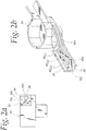
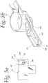
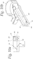
- Figs. 2-6 further illustrate five of the above described structures ( i . e ., the structures illustrated in Figs. 1c, 1d, 1g, 1f and 1i ) as configured to supply waste water to a grit removal system such as taught in previously discussed U.S. Patent No. 6,811,697 B2 .
- the baffle 60c is installed in the straight section of the channel 20c and includes a taper 70c at the front (input) or influent end to provide a smooth transition for the flow from the full channel width W T to the reduced widths defined by the steps 40 c1 , 40 c2 , 40 c3 .
- another transition may be provided which can vary in shape and angle based on the application ( e . g ., it may be tapered similar to the front end, or it may end more abruptly).
- the baffle 60c may also follow any elevation changes of the channel 20c, such as at the increased slope portion 80c dropping toward the grit removal unit 24 (as may be desirable, e.g., for grit removal units 24 of the type illustrated).
- Figs. 3-6 similarly illustrate the baffles 60d, 60g, 60f and 60i of Figs. 1d, 1g, 1f and 1i respectively, including tapers 70d, 70g, 70f and 70i at the baffle front ends, and elevation changes following the slope of sloped portions 80d, 80g, 80f and 80i of the respective channels.
- Figs. 7-11 similarly illustrate the baffles 60c, 60d, 60g, 60f and 60i of Figs. 1c, 1d, 1g, 1f and 1i respectively for input channels associated with a different design grit removal unit 24' (wherein no differently sloped portion is provided).
- These baffles similarly include the taper 70c, 70d, 70g, 70f and 70i at their front end and, as illustrated, abruptly end without a taper at the entrance to the grit removal unit 24'.
- the particular configuration of the present invention which is most suitable for a particular waste treatment facility may be advantageously determined using suitable calculations or Computational Fluid Dynamics (CFD) modeling based on the hydraulics of the application (i . e ., flow volume ranges, the degree of change in flow volumes, flow velocities, and the hydraulic profile), as well as the expected flow volumes ( i . e ., maximum [peak] flow volumes, average flow volumes, and the minimum flow volume anticipated), the time of the change between flow volumes, and the expected duration of the period of flows.
- CFD Computational Fluid Dynamics
- baffle profile that is the most effective at controlling the velocity in the channel for the expected range of flows and water depths may be advantageously used, even baffle profiles which are not most effective may nonetheless be advantageously used to improve operation of the waste water treatment system.
- the size of the baffles may also be advantageously determined so that (1) the velocity in the channel at the expected maximum flow (and consequently the highest water level) will be close to the maximum desired channel velocity and, conversely, (2) the velocity in the channel at the expected low flow volume will be near the minimum desired flow velocity. This will give the largest range of flows that will have channel velocities in the desired range.
- baffles 60 will allow for the flow velocities to be maintained in a desired range over a larger range of flow volumes (and thereby allow the associated grit removal system 24 to operate most efficiently and effectively).
- the larger range of flow volumes will thus provide advantageous operation over long periods of time.
Landscapes
- Chemical & Material Sciences (AREA)
- Chemical Kinetics & Catalysis (AREA)
- Physical Water Treatments (AREA)
- Water Treatment By Electricity Or Magnetism (AREA)
- Sewage (AREA)
Claims (9)
- Verfahren zum Herstellen eines Einlasskanals (20) zum Verhindern von Ablagerungen im Schmutzwasserfluss in eine Entsandungseinheit (24), wobei der Einlasskanal (20) eine Tiefe D hat, umfassend den Schritt des Formens einer Seitenwand des Kanals (20), um die Kanalweite über die Tiefe des Kanals (20) zu verändern, wobei:die Weite am Boden des Kanals (20) WB ist,die Weite am oberen Ende des Kanals (20) WT ist,und WB < WT ist,wobei die Weite bei einer Kanaltiefe "d" über dem Boden des Kanals Wd ist,wobei Wd größer oder gleich der Kanalweite bei jeder Kanaltiefe kleiner als "d" ist,dadurch gekennzeichnet, dassdas Verfahren ferner ein Nachrüsten eines Einlasskanals (20) umfasst, der ursprünglich mit einem flachen Boden (30) und zwei vertikalen Seiten (32, 34) vorgesehen ist, durch die Schritte:Hinzufügen eines Leitblechs (60) entlang einer Seite des Einlasskanals (20) um die vom Wasser durchströmte Querschnittsöffnung zu verringern, welches Leitblech (60) die Weite des Kanals (20) selektiv auf weniger als WT verjüngt, um eine Erhöhung der Strömungsgeschwindigkeit zu unterstützen; undFixieren des Leitblechs (60) in dem Einlasskanal (20).
- Das Verfahren nach Anspruch 1, wobei das Leitblech (60) in dem Einlasskanal (20) fixiert wird, indem zu dem Leitblech ein Gewicht hinzugefügt wird, um das Leitblech nach unten auf den Boden (30) des Einlasskanals (20) zu beschweren.
- Das Verfahren nach Anspruch 1, wobei das Leitblech (60) in dem Einlasskanal (20) fixiert wird, indem das Leitblech entlang der einen Seite in dem Einlasskanal (20) verankert wird.
- Ein nachgerüsteter Einlasskanal (20), hergestellt in dem Verfahren nach Anspruch 1, sodass die eine Seitenwand des Einlasskanals (20) von dem Leitblech (60) gebildet wird, das sich entlang der Länge des Kanals (20) erstreckt und die vom Wasser durchströmte Querschnittsöffnung des Kanals (20) verringert, der eine Tiefe d vom flachen Boden des Kanals (20) weg genommen hat; wobei erste und zweite Durchflussraten des Abwassers durch den Einlasskanal (20) erwartet werden, wobei die zweite Durchflussrate größer als die erste Durchflussrate ist, und
die eine Seitenwand in Stufen geformt ist, wobei
die Kanalweite am Boden (30) des Kanals (20) für eine Tiefe d1 gleich W1 ist,
die Kanalweite für eine Tiefe d2 oberhalb der Tiefe d1 gleich W2 ist,
W1 = WB, und
W1 < W2;
wobei eine Kanalquerschnittsöffnung von (W1 x d1) eine Wasserflussgeschwindigkeit im gewünschten Bereich für die erste Durchflussrate des Wassers ergibt; und
eine Kanalquerschnittsöffnung von ([W1 x d1] + [W2 x d2]) eine Wasserflussgeschwindigkeit im gewünschten Bereich für die zweite Durchflussrate des Wassers ergibt. - Der Einlasskanal (20) nach Anspruch 4, wobei
eine dritte Durchflussrate des Abwassers durch den Einlasskanal (20) erwartet wird,
welche dritte Durchflussrate größer als die zweite Durchflussrate ist;
wobei die Kanalweite für eine Tiefe d3 oberhalb der Tiefe d1 + d2 gleich W3 ist;
wobei W2 < W3; und
eine Kanalquerschnittsöffnung von ([W1 x d1] + [W2 x d2] + [W3 x d3]) eine Wasserflussgeschwindigkeit in dem gwünschten Bereich für die dritte Durchflussrate des Wassers ergibt. - Der Einlasskanal (20) nach Anspruch 4, wobei die erwarteten Durchflussraten des Abwassers Durchflussraten sind, die während der Auslegungslebensdauer der Entsandungseinheit (24) erwartet werden.
- Der Einlasskanal (20) nach Anspruch 4, wobei sich die erwarteten Durchflussraten des Abwassers von Durchflussraten unterscheiden, die beim Bau des Kanals (20) erwartet wurden.
- Der Einlasskanal (20) nach Anspruch 4, hergestellt nach Anspruch 3, wobei das Leitblech (60) mit einem Verankerungssystem an die eine Seite (32, 34) des Kanals grenzend fixiert ist.
- Der Einlasskanal (20) nach Anspruch 4, hergestellt nach Anspruch 2, wobei das Leitblech (60) hohl ist und mit einem Gewicht gefüllt ist, ausreichend um das Leitblech (60) auf dem Boden (30) des Einlasskanals (20) zu halten.
Applications Claiming Priority (2)
| Application Number | Priority Date | Filing Date | Title |
|---|---|---|---|
| US12/818,355 US8460560B2 (en) | 2010-06-18 | 2010-06-18 | Variable influent flow channel baffle |
| PCT/US2011/037715 WO2011159438A1 (en) | 2010-06-18 | 2011-05-24 | Variable influent flow channel baffle |
Publications (3)
| Publication Number | Publication Date |
|---|---|
| EP2582439A1 EP2582439A1 (de) | 2013-04-24 |
| EP2582439A4 EP2582439A4 (de) | 2014-07-16 |
| EP2582439B1 true EP2582439B1 (de) | 2019-03-06 |
Family
ID=45327615
Family Applications (1)
| Application Number | Title | Priority Date | Filing Date |
|---|---|---|---|
| EP11796137.5A Active EP2582439B1 (de) | 2010-06-18 | 2011-05-24 | Verfahren zur Herstellung eines Einlaufkanals, und ein nachgerüsteter Einlaufkanal |
Country Status (6)
| Country | Link |
|---|---|
| US (1) | US8460560B2 (de) |
| EP (1) | EP2582439B1 (de) |
| AU (1) | AU2011265710B2 (de) |
| CA (1) | CA2802160C (de) |
| NZ (2) | NZ604041A (de) |
| WO (1) | WO2011159438A1 (de) |
Families Citing this family (1)
| Publication number | Priority date | Publication date | Assignee | Title |
|---|---|---|---|---|
| US9334178B2 (en) * | 2012-11-08 | 2016-05-10 | Smith & Loveless Inc. | Vortex-type grit chamber |
Family Cites Families (21)
| Publication number | Priority date | Publication date | Assignee | Title |
|---|---|---|---|---|
| US2425932A (en) * | 1947-08-19 | Gkit separator | ||
| US2025722A (en) | 1933-07-20 | 1935-12-31 | Thomas R Camp | Flow control apparatus |
| US2281826A (en) | 1938-02-17 | 1942-05-05 | Thomas R Camp | Flow control apparatus |
| US2573905A (en) | 1946-11-20 | 1951-11-06 | Hannah J Hapman | Sludge removing system |
| US3962084A (en) * | 1973-06-15 | 1976-06-08 | Gert Nussbaum | Rain storing tank |
| US3891557A (en) * | 1974-02-11 | 1975-06-24 | Fmc Corp | Peripheral feed clarification tank |
| US3941698A (en) | 1974-02-19 | 1976-03-02 | Ecodyne Corporation | Grit selector |
| US4107038A (en) | 1977-08-12 | 1978-08-15 | Ecodyne Corporation | Method and apparatus for removing grit |
| GB2148744B (en) * | 1983-11-02 | 1986-06-25 | Jones & Attwood Ltd | Grit trap |
| US4767532A (en) | 1987-05-21 | 1988-08-30 | Smith & Loveless, Inc. | Apparatus for removing grit |
| GB9005418D0 (en) | 1990-03-10 | 1990-05-09 | Hydraulic Design Ltd | Method and apparatus for removing grit from sewage |
| US5759415A (en) * | 1991-10-02 | 1998-06-02 | Vortechnics, Inc. | Method and apparatus for separating floating and non-floating particulate from rainwater drainage |
| US5300220A (en) * | 1992-06-29 | 1994-04-05 | Henry Filters, Inc. | Trough system for machine tool coolant collection flumes |
| DE4224047C2 (de) * | 1992-07-21 | 1998-03-26 | Anton Felder | Vorrichtung und Verfahren zur zentrischen Beschickung von Rundsandfängen und Sandklassierern in Rundbauweise |
| JP2981960B2 (ja) | 1993-06-04 | 1999-11-22 | アクアテック株式会社 | 固形物流離分離方法 |
| FR2725143B1 (fr) | 1994-10-04 | 1999-08-06 | Degremont | Decanteur longitudinal a separation de flux |
| US7278239B1 (en) | 1999-11-03 | 2007-10-09 | Lauriston Enterprises Pty Ltd. | Gutter protector and guttering incorporating same |
| US6598352B2 (en) | 2001-08-07 | 2003-07-29 | Edward A. Higginbotham | Self cleaning gutter shield |
| US6811697B2 (en) * | 2001-10-26 | 2004-11-02 | Smith & Loveless | Apparatus and method for extracting particles from a fluid stream |
| US7971732B2 (en) | 2006-11-06 | 2011-07-05 | Smith & Loveless, Inc. | Grit trap for waste water system |
| EP2451575A2 (de) * | 2009-07-07 | 2012-05-16 | Boehringer Ingelheim Microparts GmbH | Plasmaabscheidungsreservoir |
-
2010
- 2010-06-18 US US12/818,355 patent/US8460560B2/en active Active
-
2011
- 2011-05-24 AU AU2011265710A patent/AU2011265710B2/en active Active
- 2011-05-24 EP EP11796137.5A patent/EP2582439B1/de active Active
- 2011-05-24 NZ NZ60404111A patent/NZ604041A/en unknown
- 2011-05-24 WO PCT/US2011/037715 patent/WO2011159438A1/en not_active Ceased
- 2011-05-24 NZ NZ617871A patent/NZ617871A/en unknown
- 2011-05-24 CA CA2802160A patent/CA2802160C/en active Active
Non-Patent Citations (1)
| Title |
|---|
| None * |
Also Published As
| Publication number | Publication date |
|---|---|
| US20110308661A1 (en) | 2011-12-22 |
| AU2011265710A1 (en) | 2013-01-10 |
| EP2582439A4 (de) | 2014-07-16 |
| NZ617871A (en) | 2015-02-27 |
| CA2802160A1 (en) | 2011-12-22 |
| EP2582439A1 (de) | 2013-04-24 |
| US8460560B2 (en) | 2013-06-11 |
| NZ604041A (en) | 2014-04-30 |
| CA2802160C (en) | 2016-08-09 |
| WO2011159438A1 (en) | 2011-12-22 |
| AU2011265710B2 (en) | 2015-04-16 |
Similar Documents
| Publication | Publication Date | Title |
|---|---|---|
| US6350374B1 (en) | Stormwater treatment apparatus | |
| US7582216B2 (en) | Water treatment and bypass system | |
| Brouckaert et al. | The use of computational fluid dynamics for improving the design and operation of water and wastewater treatment plants | |
| NZ261815A (en) | Solids separated from flowing liquid by panel cleaned by liquid flow | |
| GB2294411A (en) | A Water Treatment Tank | |
| WO2005084778A1 (en) | Vane diffuser | |
| US7507333B2 (en) | Method of and apparatus for cleaning runoff water | |
| US6868971B2 (en) | Solids/liquids separator | |
| US9480939B2 (en) | Underdrain and method for transferring forces and directing flow | |
| CA2802160C (en) | Variable influent flow channel baffle | |
| US10472815B1 (en) | Hydro-variant baffle cartridge system | |
| US5795467A (en) | Adjustable inlet for waste water treatment apparatus | |
| CN108996678A (zh) | 一种污水设施过流用降跌消氧装置 | |
| Milovanović et al. | Enhancing stormwater sediment settling at detention pond inlets by a bottom grid structure (BGS) | |
| US5895579A (en) | Adjustable inlet for waste water treatment apparatus | |
| EP2480303A1 (de) | Abscheider | |
| KR20100069524A (ko) | 침전물 퇴적 방지용 수중보 구조물 | |
| Marais et al. | Design of grit channels controlled by Parshall flumes | |
| AU713900B1 (en) | Linear buoyancy separation device | |
| El-Etriby | Using of Plate Settlers for Wastewater Grit Removal. | |
| AU2004242447B2 (en) | Solids/liquids separator | |
| AU2016224126B2 (en) | Dewatering tank | |
| KR200338729Y1 (ko) | 배수량의 저하를 방지하는 하수구용 구조물 | |
| JP2004502063A (ja) | 下射式越流フィルター | |
| AU2001256005A1 (en) | Solids/liquids separator |
Legal Events
| Date | Code | Title | Description |
|---|---|---|---|
| PUAI | Public reference made under article 153(3) epc to a published international application that has entered the european phase |
Free format text: ORIGINAL CODE: 0009012 |
|
| 17P | Request for examination filed |
Effective date: 20130117 |
|
| AK | Designated contracting states |
Kind code of ref document: A1 Designated state(s): AL AT BE BG CH CY CZ DE DK EE ES FI FR GB GR HR HU IE IS IT LI LT LU LV MC MK MT NL NO PL PT RO RS SE SI SK SM TR |
|
| DAX | Request for extension of the european patent (deleted) | ||
| RIC1 | Information provided on ipc code assigned before grant |
Ipc: B04C 3/06 20060101ALI20140605BHEP Ipc: B01D 21/24 20060101AFI20140605BHEP Ipc: B01D 21/26 20060101ALI20140605BHEP |
|
| A4 | Supplementary search report drawn up and despatched |
Effective date: 20140617 |
|
| RIC1 | Information provided on ipc code assigned before grant |
Ipc: B01D 21/26 20060101ALI20140611BHEP Ipc: B01D 21/24 20060101AFI20140611BHEP Ipc: B04C 3/06 20060101ALI20140611BHEP |
|
| STAA | Information on the status of an ep patent application or granted ep patent |
Free format text: STATUS: EXAMINATION IS IN PROGRESS |
|
| 17Q | First examination report despatched |
Effective date: 20161031 |
|
| RIC1 | Information provided on ipc code assigned before grant |
Ipc: B01D 21/24 20060101AFI20180726BHEP Ipc: B01D 21/26 20060101ALI20180726BHEP |
|
| GRAP | Despatch of communication of intention to grant a patent |
Free format text: ORIGINAL CODE: EPIDOSNIGR1 |
|
| STAA | Information on the status of an ep patent application or granted ep patent |
Free format text: STATUS: GRANT OF PATENT IS INTENDED |
|
| INTG | Intention to grant announced |
Effective date: 20180831 |
|
| GRAS | Grant fee paid |
Free format text: ORIGINAL CODE: EPIDOSNIGR3 |
|
| GRAA | (expected) grant |
Free format text: ORIGINAL CODE: 0009210 |
|
| STAA | Information on the status of an ep patent application or granted ep patent |
Free format text: STATUS: THE PATENT HAS BEEN GRANTED |
|
| AK | Designated contracting states |
Kind code of ref document: B1 Designated state(s): AL AT BE BG CH CY CZ DE DK EE ES FI FR GB GR HR HU IE IS IT LI LT LU LV MC MK MT NL NO PL PT RO RS SE SI SK SM TR |
|
| REG | Reference to a national code |
Ref country code: GB Ref legal event code: FG4D |
|
| REG | Reference to a national code |
Ref country code: CH Ref legal event code: EP Ref country code: AT Ref legal event code: REF Ref document number: 1103781 Country of ref document: AT Kind code of ref document: T Effective date: 20190315 |
|
| REG | Reference to a national code |
Ref country code: DE Ref legal event code: R096 Ref document number: 602011056923 Country of ref document: DE |
|
| REG | Reference to a national code |
Ref country code: IE Ref legal event code: FG4D |
|
| REG | Reference to a national code |
Ref country code: NL Ref legal event code: MP Effective date: 20190306 |
|
| REG | Reference to a national code |
Ref country code: LT Ref legal event code: MG4D |
|
| PG25 | Lapsed in a contracting state [announced via postgrant information from national office to epo] |
Ref country code: LT Free format text: LAPSE BECAUSE OF FAILURE TO SUBMIT A TRANSLATION OF THE DESCRIPTION OR TO PAY THE FEE WITHIN THE PRESCRIBED TIME-LIMIT Effective date: 20190306 Ref country code: FI Free format text: LAPSE BECAUSE OF FAILURE TO SUBMIT A TRANSLATION OF THE DESCRIPTION OR TO PAY THE FEE WITHIN THE PRESCRIBED TIME-LIMIT Effective date: 20190306 Ref country code: NO Free format text: LAPSE BECAUSE OF FAILURE TO SUBMIT A TRANSLATION OF THE DESCRIPTION OR TO PAY THE FEE WITHIN THE PRESCRIBED TIME-LIMIT Effective date: 20190606 Ref country code: SE Free format text: LAPSE BECAUSE OF FAILURE TO SUBMIT A TRANSLATION OF THE DESCRIPTION OR TO PAY THE FEE WITHIN THE PRESCRIBED TIME-LIMIT Effective date: 20190306 |
|
| PG25 | Lapsed in a contracting state [announced via postgrant information from national office to epo] |
Ref country code: NL Free format text: LAPSE BECAUSE OF FAILURE TO SUBMIT A TRANSLATION OF THE DESCRIPTION OR TO PAY THE FEE WITHIN THE PRESCRIBED TIME-LIMIT Effective date: 20190306 Ref country code: RS Free format text: LAPSE BECAUSE OF FAILURE TO SUBMIT A TRANSLATION OF THE DESCRIPTION OR TO PAY THE FEE WITHIN THE PRESCRIBED TIME-LIMIT Effective date: 20190306 Ref country code: BG Free format text: LAPSE BECAUSE OF FAILURE TO SUBMIT A TRANSLATION OF THE DESCRIPTION OR TO PAY THE FEE WITHIN THE PRESCRIBED TIME-LIMIT Effective date: 20190606 Ref country code: LV Free format text: LAPSE BECAUSE OF FAILURE TO SUBMIT A TRANSLATION OF THE DESCRIPTION OR TO PAY THE FEE WITHIN THE PRESCRIBED TIME-LIMIT Effective date: 20190306 Ref country code: HR Free format text: LAPSE BECAUSE OF FAILURE TO SUBMIT A TRANSLATION OF THE DESCRIPTION OR TO PAY THE FEE WITHIN THE PRESCRIBED TIME-LIMIT Effective date: 20190306 Ref country code: GR Free format text: LAPSE BECAUSE OF FAILURE TO SUBMIT A TRANSLATION OF THE DESCRIPTION OR TO PAY THE FEE WITHIN THE PRESCRIBED TIME-LIMIT Effective date: 20190607 |
|
| REG | Reference to a national code |
Ref country code: AT Ref legal event code: MK05 Ref document number: 1103781 Country of ref document: AT Kind code of ref document: T Effective date: 20190306 |
|
| PG25 | Lapsed in a contracting state [announced via postgrant information from national office to epo] |
Ref country code: PT Free format text: LAPSE BECAUSE OF FAILURE TO SUBMIT A TRANSLATION OF THE DESCRIPTION OR TO PAY THE FEE WITHIN THE PRESCRIBED TIME-LIMIT Effective date: 20190706 Ref country code: ES Free format text: LAPSE BECAUSE OF FAILURE TO SUBMIT A TRANSLATION OF THE DESCRIPTION OR TO PAY THE FEE WITHIN THE PRESCRIBED TIME-LIMIT Effective date: 20190306 Ref country code: AL Free format text: LAPSE BECAUSE OF FAILURE TO SUBMIT A TRANSLATION OF THE DESCRIPTION OR TO PAY THE FEE WITHIN THE PRESCRIBED TIME-LIMIT Effective date: 20190306 Ref country code: SK Free format text: LAPSE BECAUSE OF FAILURE TO SUBMIT A TRANSLATION OF THE DESCRIPTION OR TO PAY THE FEE WITHIN THE PRESCRIBED TIME-LIMIT Effective date: 20190306 Ref country code: EE Free format text: LAPSE BECAUSE OF FAILURE TO SUBMIT A TRANSLATION OF THE DESCRIPTION OR TO PAY THE FEE WITHIN THE PRESCRIBED TIME-LIMIT Effective date: 20190306 Ref country code: IT Free format text: LAPSE BECAUSE OF FAILURE TO SUBMIT A TRANSLATION OF THE DESCRIPTION OR TO PAY THE FEE WITHIN THE PRESCRIBED TIME-LIMIT Effective date: 20190306 Ref country code: CZ Free format text: LAPSE BECAUSE OF FAILURE TO SUBMIT A TRANSLATION OF THE DESCRIPTION OR TO PAY THE FEE WITHIN THE PRESCRIBED TIME-LIMIT Effective date: 20190306 Ref country code: RO Free format text: LAPSE BECAUSE OF FAILURE TO SUBMIT A TRANSLATION OF THE DESCRIPTION OR TO PAY THE FEE WITHIN THE PRESCRIBED TIME-LIMIT Effective date: 20190306 |
|
| PG25 | Lapsed in a contracting state [announced via postgrant information from national office to epo] |
Ref country code: PL Free format text: LAPSE BECAUSE OF FAILURE TO SUBMIT A TRANSLATION OF THE DESCRIPTION OR TO PAY THE FEE WITHIN THE PRESCRIBED TIME-LIMIT Effective date: 20190306 Ref country code: SM Free format text: LAPSE BECAUSE OF FAILURE TO SUBMIT A TRANSLATION OF THE DESCRIPTION OR TO PAY THE FEE WITHIN THE PRESCRIBED TIME-LIMIT Effective date: 20190306 |
|
| REG | Reference to a national code |
Ref country code: DE Ref legal event code: R119 Ref document number: 602011056923 Country of ref document: DE |
|
| REG | Reference to a national code |
Ref country code: CH Ref legal event code: PL |
|
| PG25 | Lapsed in a contracting state [announced via postgrant information from national office to epo] |
Ref country code: IS Free format text: LAPSE BECAUSE OF FAILURE TO SUBMIT A TRANSLATION OF THE DESCRIPTION OR TO PAY THE FEE WITHIN THE PRESCRIBED TIME-LIMIT Effective date: 20190706 Ref country code: AT Free format text: LAPSE BECAUSE OF FAILURE TO SUBMIT A TRANSLATION OF THE DESCRIPTION OR TO PAY THE FEE WITHIN THE PRESCRIBED TIME-LIMIT Effective date: 20190306 |
|
| PLBE | No opposition filed within time limit |
Free format text: ORIGINAL CODE: 0009261 |
|
| STAA | Information on the status of an ep patent application or granted ep patent |
Free format text: STATUS: NO OPPOSITION FILED WITHIN TIME LIMIT |
|
| PG25 | Lapsed in a contracting state [announced via postgrant information from national office to epo] |
Ref country code: MC Free format text: LAPSE BECAUSE OF FAILURE TO SUBMIT A TRANSLATION OF THE DESCRIPTION OR TO PAY THE FEE WITHIN THE PRESCRIBED TIME-LIMIT Effective date: 20190306 Ref country code: LI Free format text: LAPSE BECAUSE OF NON-PAYMENT OF DUE FEES Effective date: 20190531 Ref country code: DK Free format text: LAPSE BECAUSE OF FAILURE TO SUBMIT A TRANSLATION OF THE DESCRIPTION OR TO PAY THE FEE WITHIN THE PRESCRIBED TIME-LIMIT Effective date: 20190306 Ref country code: CH Free format text: LAPSE BECAUSE OF NON-PAYMENT OF DUE FEES Effective date: 20190531 |
|
| REG | Reference to a national code |
Ref country code: BE Ref legal event code: MM Effective date: 20190531 |
|
| 26N | No opposition filed |
Effective date: 20191209 |
|
| PG25 | Lapsed in a contracting state [announced via postgrant information from national office to epo] |
Ref country code: LU Free format text: LAPSE BECAUSE OF NON-PAYMENT OF DUE FEES Effective date: 20190524 Ref country code: SI Free format text: LAPSE BECAUSE OF FAILURE TO SUBMIT A TRANSLATION OF THE DESCRIPTION OR TO PAY THE FEE WITHIN THE PRESCRIBED TIME-LIMIT Effective date: 20190306 |
|
| PG25 | Lapsed in a contracting state [announced via postgrant information from national office to epo] |
Ref country code: TR Free format text: LAPSE BECAUSE OF FAILURE TO SUBMIT A TRANSLATION OF THE DESCRIPTION OR TO PAY THE FEE WITHIN THE PRESCRIBED TIME-LIMIT Effective date: 20190306 |
|
| PG25 | Lapsed in a contracting state [announced via postgrant information from national office to epo] |
Ref country code: IE Free format text: LAPSE BECAUSE OF NON-PAYMENT OF DUE FEES Effective date: 20190524 Ref country code: DE Free format text: LAPSE BECAUSE OF NON-PAYMENT OF DUE FEES Effective date: 20191203 |
|
| PG25 | Lapsed in a contracting state [announced via postgrant information from national office to epo] |
Ref country code: BE Free format text: LAPSE BECAUSE OF NON-PAYMENT OF DUE FEES Effective date: 20190531 |
|
| PG25 | Lapsed in a contracting state [announced via postgrant information from national office to epo] |
Ref country code: FR Free format text: LAPSE BECAUSE OF NON-PAYMENT OF DUE FEES Effective date: 20190531 |
|
| PG25 | Lapsed in a contracting state [announced via postgrant information from national office to epo] |
Ref country code: CY Free format text: LAPSE BECAUSE OF FAILURE TO SUBMIT A TRANSLATION OF THE DESCRIPTION OR TO PAY THE FEE WITHIN THE PRESCRIBED TIME-LIMIT Effective date: 20190306 |
|
| PG25 | Lapsed in a contracting state [announced via postgrant information from national office to epo] |
Ref country code: MT Free format text: LAPSE BECAUSE OF FAILURE TO SUBMIT A TRANSLATION OF THE DESCRIPTION OR TO PAY THE FEE WITHIN THE PRESCRIBED TIME-LIMIT Effective date: 20190306 Ref country code: HU Free format text: LAPSE BECAUSE OF FAILURE TO SUBMIT A TRANSLATION OF THE DESCRIPTION OR TO PAY THE FEE WITHIN THE PRESCRIBED TIME-LIMIT; INVALID AB INITIO Effective date: 20110524 |
|
| PG25 | Lapsed in a contracting state [announced via postgrant information from national office to epo] |
Ref country code: MK Free format text: LAPSE BECAUSE OF FAILURE TO SUBMIT A TRANSLATION OF THE DESCRIPTION OR TO PAY THE FEE WITHIN THE PRESCRIBED TIME-LIMIT Effective date: 20190306 |
|
| PGFP | Annual fee paid to national office [announced via postgrant information from national office to epo] |
Ref country code: GB Payment date: 20250527 Year of fee payment: 15 |