EP2582010A1 - Vehicle battery-pack equalization system and vehicle battery-pack equalization method - Google Patents
Vehicle battery-pack equalization system and vehicle battery-pack equalization method Download PDFInfo
- Publication number
- EP2582010A1 EP2582010A1 EP10852874.6A EP10852874A EP2582010A1 EP 2582010 A1 EP2582010 A1 EP 2582010A1 EP 10852874 A EP10852874 A EP 10852874A EP 2582010 A1 EP2582010 A1 EP 2582010A1
- Authority
- EP
- European Patent Office
- Prior art keywords
- equalization
- vehicle
- processing time
- pack
- time period
- Prior art date
- Legal status (The legal status is an assumption and is not a legal conclusion. Google has not performed a legal analysis and makes no representation as to the accuracy of the status listed.)
- Granted
Links
- 238000000034 method Methods 0.000 title claims description 100
- 238000007599 discharging Methods 0.000 claims abstract description 11
- 230000004044 response Effects 0.000 claims description 6
- HBBGRARXTFLTSG-UHFFFAOYSA-N Lithium ion Chemical compound [Li+] HBBGRARXTFLTSG-UHFFFAOYSA-N 0.000 description 3
- PXHVJJICTQNCMI-UHFFFAOYSA-N Nickel Chemical compound [Ni] PXHVJJICTQNCMI-UHFFFAOYSA-N 0.000 description 3
- 229910001416 lithium ion Inorganic materials 0.000 description 3
- 238000012544 monitoring process Methods 0.000 description 3
- 229910000652 nickel hydride Inorganic materials 0.000 description 3
- 239000003990 capacitor Substances 0.000 description 2
- 238000010586 diagram Methods 0.000 description 1
- 230000000694 effects Effects 0.000 description 1
- 230000010287 polarization Effects 0.000 description 1
- 238000004904 shortening Methods 0.000 description 1
Images


Classifications
-
- H—ELECTRICITY
- H01—ELECTRIC ELEMENTS
- H01M—PROCESSES OR MEANS, e.g. BATTERIES, FOR THE DIRECT CONVERSION OF CHEMICAL ENERGY INTO ELECTRICAL ENERGY
- H01M10/00—Secondary cells; Manufacture thereof
- H01M10/42—Methods or arrangements for servicing or maintenance of secondary cells or secondary half-cells
- H01M10/44—Methods for charging or discharging
- H01M10/441—Methods for charging or discharging for several batteries or cells simultaneously or sequentially
-
- B—PERFORMING OPERATIONS; TRANSPORTING
- B60—VEHICLES IN GENERAL
- B60L—PROPULSION OF ELECTRICALLY-PROPELLED VEHICLES; SUPPLYING ELECTRIC POWER FOR AUXILIARY EQUIPMENT OF ELECTRICALLY-PROPELLED VEHICLES; ELECTRODYNAMIC BRAKE SYSTEMS FOR VEHICLES IN GENERAL; MAGNETIC SUSPENSION OR LEVITATION FOR VEHICLES; MONITORING OPERATING VARIABLES OF ELECTRICALLY-PROPELLED VEHICLES; ELECTRIC SAFETY DEVICES FOR ELECTRICALLY-PROPELLED VEHICLES
- B60L3/00—Electric devices on electrically-propelled vehicles for safety purposes; Monitoring operating variables, e.g. speed, deceleration or energy consumption
- B60L3/0023—Detecting, eliminating, remedying or compensating for drive train abnormalities, e.g. failures within the drive train
- B60L3/0046—Detecting, eliminating, remedying or compensating for drive train abnormalities, e.g. failures within the drive train relating to electric energy storage systems, e.g. batteries or capacitors
-
- B—PERFORMING OPERATIONS; TRANSPORTING
- B60—VEHICLES IN GENERAL
- B60L—PROPULSION OF ELECTRICALLY-PROPELLED VEHICLES; SUPPLYING ELECTRIC POWER FOR AUXILIARY EQUIPMENT OF ELECTRICALLY-PROPELLED VEHICLES; ELECTRODYNAMIC BRAKE SYSTEMS FOR VEHICLES IN GENERAL; MAGNETIC SUSPENSION OR LEVITATION FOR VEHICLES; MONITORING OPERATING VARIABLES OF ELECTRICALLY-PROPELLED VEHICLES; ELECTRIC SAFETY DEVICES FOR ELECTRICALLY-PROPELLED VEHICLES
- B60L58/00—Methods or circuit arrangements for monitoring or controlling batteries or fuel cells, specially adapted for electric vehicles
- B60L58/10—Methods or circuit arrangements for monitoring or controlling batteries or fuel cells, specially adapted for electric vehicles for monitoring or controlling batteries
- B60L58/18—Methods or circuit arrangements for monitoring or controlling batteries or fuel cells, specially adapted for electric vehicles for monitoring or controlling batteries of two or more battery modules
- B60L58/22—Balancing the charge of battery modules
-
- H—ELECTRICITY
- H02—GENERATION; CONVERSION OR DISTRIBUTION OF ELECTRIC POWER
- H02J—CIRCUIT ARRANGEMENTS OR SYSTEMS FOR SUPPLYING OR DISTRIBUTING ELECTRIC POWER; SYSTEMS FOR STORING ELECTRIC ENERGY
- H02J7/00—Circuit arrangements for charging or depolarising batteries or for supplying loads from batteries
- H02J7/0013—Circuit arrangements for charging or depolarising batteries or for supplying loads from batteries acting upon several batteries simultaneously or sequentially
- H02J7/0014—Circuits for equalisation of charge between batteries
- H02J7/0016—Circuits for equalisation of charge between batteries using shunting, discharge or bypass circuits
-
- H—ELECTRICITY
- H01—ELECTRIC ELEMENTS
- H01M—PROCESSES OR MEANS, e.g. BATTERIES, FOR THE DIRECT CONVERSION OF CHEMICAL ENERGY INTO ELECTRICAL ENERGY
- H01M2220/00—Batteries for particular applications
- H01M2220/20—Batteries in motive systems, e.g. vehicle, ship, plane
-
- Y—GENERAL TAGGING OF NEW TECHNOLOGICAL DEVELOPMENTS; GENERAL TAGGING OF CROSS-SECTIONAL TECHNOLOGIES SPANNING OVER SEVERAL SECTIONS OF THE IPC; TECHNICAL SUBJECTS COVERED BY FORMER USPC CROSS-REFERENCE ART COLLECTIONS [XRACs] AND DIGESTS
- Y02—TECHNOLOGIES OR APPLICATIONS FOR MITIGATION OR ADAPTATION AGAINST CLIMATE CHANGE
- Y02E—REDUCTION OF GREENHOUSE GAS [GHG] EMISSIONS, RELATED TO ENERGY GENERATION, TRANSMISSION OR DISTRIBUTION
- Y02E60/00—Enabling technologies; Technologies with a potential or indirect contribution to GHG emissions mitigation
- Y02E60/10—Energy storage using batteries
-
- Y—GENERAL TAGGING OF NEW TECHNOLOGICAL DEVELOPMENTS; GENERAL TAGGING OF CROSS-SECTIONAL TECHNOLOGIES SPANNING OVER SEVERAL SECTIONS OF THE IPC; TECHNICAL SUBJECTS COVERED BY FORMER USPC CROSS-REFERENCE ART COLLECTIONS [XRACs] AND DIGESTS
- Y02—TECHNOLOGIES OR APPLICATIONS FOR MITIGATION OR ADAPTATION AGAINST CLIMATE CHANGE
- Y02T—CLIMATE CHANGE MITIGATION TECHNOLOGIES RELATED TO TRANSPORTATION
- Y02T10/00—Road transport of goods or passengers
- Y02T10/60—Other road transportation technologies with climate change mitigation effect
- Y02T10/70—Energy storage systems for electromobility, e.g. batteries
Definitions
- the present invention relates to a system and method for equalizing a voltage of each of two or more cells connected in series in a battery pack.
- Such electrically-driven vehicles often use, as a power supply, a battery pack in which two or more nickel hydride or lithium ion secondary cells serving as unit cells are connected in series.
- a voltage variation at both ends of unit cells may be caused depending on a charged state (remaining capacity, or state of charge (SOC)) of each unit cell. If charging and discharging are continued with the voltage variation left unremoved, it may become easier for some unit cells to reach the upper or lower limit of cell voltage, resulting in a reduced usable range of the battery pack and shorter travel distance of the electrically-driven vehicle.
- SOC state of charge
- Patent Document 1 discloses that the equalization of unit cells is accomplished by repeating, for a predetermined period, moving charges to a capacitor from a unit cell having a voltage at both ends higher than any other unit cells, and then moving charges from the capacitor to a unit cell having a voltage at both ends lower than any other unit cells.
- Patent Document 2 discloses that equalization is performed slowly for a long period of time (about a few hours to one day) and stopped after a predetermined time elapses. Patent Document 2 further describes that the predetermined time to perform equalization is changed in accordance with an instruction from a user or ambient temperature of the vehicle.
- Patent Document 3 When equalization of unit cells is performed with an ignition switch of a vehicle being turned OFF, some electric power from the electric source for the vehicle is consumed. Therefore, in order to reduce the electric power required for the equalization process, it is suggested that a temperature variation in a battery pack is sensed in order to avoid the equalization process of the unit cells when the sensed temperature variation is within a predetermined range (for example, Patent Document 3).
- Patent Document 3 further describes that a predetermined time interval to perform an equalization process is set in a timer such that the voltage state of a battery pack is monitored in order to determine whether or not discharge for equalization is necessary; and that an equalization process is performed when the discharge for equalization is determined necessary.
- An object of the present invention is to reduce electric power consumption required for an equalization process in a vehicle battery-pack equalization system.
- a vehicle battery-pack equalization system is characterized by a system that equalizes a voltage or a remaining capacity (SOC) of each of a plurality of cells connected in series in a battery pack mounted on a vehicle by discharging each of the plurality of cells, wherein equalization processing time of each of the cells is set to a time period which is obtained by multiplying a discharge time period of the battery pack immediately before an equalization process by a ratio of difference of an electric current discharged from each of the cells with respect to an equalization discharge electric current.
- SOC remaining capacity
- the equalization processing time of each of the cells for a next equalization process is set to a time period which is obtained by adding a discharge time period of the battery pack immediately before the next equalization process multiplied by a ratio of difference of an electric current discharged from each of the cells with respect to the equalization discharge electric current and a difference between an actual equalization processing time at a previous equalization process and a setting of the equalization processing time for the previous equalization process.
- the vehicle includes an ignition switch that starts and stops the vehicle, and in response to turning OFF of the ignition switch, setting of the equalization processing time is started, and the equalization process is started after the equalization processing time is set. Also, preferably, when the ignition switch is turned ON before the set equalization processing time elapses, the equalization process is interrupted.
- a vehicle battery-pack equalization method is characterized by a method that equalizes a voltage or a remaining capacity (SOC) of each of a plurality of cells connected in series in a battery pack mounted on a vehicle by discharging each of the plurality of cells, wherein an equalization process is started after setting an equalization processing time of each of the cells to a time period which is obtained by multiplying a discharge time period of the battery pack immediately before the equalization process by a ratio of difference of an electric current discharged from each of the cells with respect to an equalization discharge electric current.
- SOC remaining capacity
- the equalization processing time of each of the cells for a next equalization process is set to a time period which is obtained by adding a discharge time period of the battery pack immediately before the next equalization process multiplied by a ratio of difference of an electric current discharged from each of the cells with respect to the equalization discharge electric current and a difference between an actual equalization processing time at a previous equalization process and a setting of the equalization processing time for the previous equalization process.
- the vehicle includes an ignition switch that starts and stops the vehicle, and in response to turning OFF of the ignition switch, setting of the equalization processing time is started. Also, preferably, when the ignition switch is turned ON before the set equalization processing time elapses, the equalization process is interrupted.
- the present invention achieves an advantage that electric power consumption required for an equalization process can be reduced in a vehicle battery-pack equalization system.
- the battery pack 10 to which the equalization process is applied is described as unit cells 11 of nickel hydride or lithium ion secondary cells connected in series as a high-voltage battery, unit cells of other types may be combined. In such a case, each of the unit cells 11 corresponds to each of the cells defined in Claim 1. Further, the battery pack 10 may be formed by two or more battery blocks connected in series, each of which includes two or more unit cells connected in series. In such a case, each battery block corresponds to each of the cells defined in Claim 1.
- a vehicle battery-pack equalization system 100 includes voltage sensors 20 for measuring a voltage of each unit cell 11 of a battery pack 10 in which two or more unit cells 11 are connected in series; an equalization circuit 40 for equalizing a voltage of each unit cell 11; and an equalization controller 30 for outputting an instruction on the operation of the equalization circuit 40 in accordance with an input from the voltage sensors 20.
- dash-dot lines represent signal lines.
- the battery pack 10 is a high-voltage battery formed by connecting, in series, two or more unit cells 11 of nickel hydride or lithium ion secondary cell. Each end of the battery pack 10 is connected, via an inverter or the like, to a load 62 such as a vehicle driving motor. Further, a system relay 63 is provided between the load 62 and the battery pack 10 for disconnecting the connection between the load 62 and the battery pack 10.
- Each of voltage sensors 20 for detecting a voltage of each unit cell 11 includes a voltage divider resistor 21 which is connected in parallel to each unit cell 11, and an op-amp 22 which is connected between a negative side of the respective voltage divider resistor 21 and a negative side of the respective unit cell 11. All the voltage divider resistors 21 have the same resistance and are arranged in series in relation to each other. The two ends of each voltage divider resistor 21 are respectively connected to a plus-side electrical path 12 and a minus-side electrical path 13 of the battery pack 10. An output of each op-amp 22 is connected to the equalization controller 30 via an interface (not shown) such that the signal is input to the equalization controller 30.
- a voltage at both ends of each voltage divider resistor 21 is an average voltage of the unit cells 11 which can be obtained by dividing the overall voltage of the battery pack 10 by the number of unit cells 11.
- Each op-amp 22 outputs a voltage difference between a voltage of the respective unit cell 11 and the average voltage of the unit cells 11. Further, each op-amp 22 is configured to be driven by electric power supplied, via a switch 23, from the respective unit cell 11 from which the op-amp 22 senses the voltage difference.
- Each switch 23 is connected to the equalization controller 30 and is configured to be turned ON and OFF in accordance with an instruction from the equalization controller 30.
- unit discharge circuits 43 each of which includes a discharge resistor 41 and an ON/OFF switch 42 connected in series with the discharge resistor 41, are connected in series in the same number as the unit cells.
- the ends of the equalization circuit 40 are respectively connected to the plus-side electrical path 12 and the minus-side electrical path 13 of the battery pack 10.
- the two ends of each unit discharge circuit 43 are connected to a plus-side end and a minus-side end of each unit cell 11 via a respective connection line 14.
- Each unit discharge circuit 43 is arranged to be in parallel with the corresponding unit cell 11.
- each ON/OFF switch 42 of each unit discharge circuit 43 is connected to the equalization controller 30 via an interface (not shown) such that each ON/OFF switch is turned ON/OFF in accordance with an instruction from the equalization controller 30.
- the equalization controller 30 is a computer which includes a CPU 31 for processing signals and a memory 32.
- the memory 32 includes an equalization processing time setting unit 33 for setting a time period for performing an equalization process which equalizes a voltage among unit cells 11; an Equalization processing unit 34 for performing the equalization process for the set time period; a time counter 35 for counting the time period in which the equalization process is performed; control data 36 which include data such as discharge characteristics of each unit cell 11; and a memory stack 37 for storing a remaining time period for the equalization process of each unit cell 11, described below.
- An electrically-driven vehicle on which the vehicle battery-pack equalization system 100 according to the present embodiment is mounted includes a controller 50 for controlling ON and OFF of a power supply of the electrically-driven vehicle and electric power supplied to the load 62, and a power supply 54 for supplying electric power for driving the equalization controller 30.
- a power supply line 55 for supplying electric power from the power supply 54 to the equalization controller 30 is a power supply switch 56 which disconnects a connection between the power supply 54 and the equalization controller 30.
- an ignition switch 61 is provided with the electrically-driven vehicle for starting and stopping the vehicle.
- the controller 50 is a computer which includes a CPU 51 for processing signals and a memory 52 in which control programs and data are stored.
- the controller 50 is configured to be connected with the equalization controller 30 to exchange signals and data therebetween.
- the power supply switch 56, the system relay 63, and the load 62 are connected to the controller 50 via respective interfaces (not shown) and configured to be operated in accordance with an instruction from the controller 50.
- the ignition switch 61 is connected to the controller 50 via an interface (not shown) such that a signal indicating whether a driver has turned ON or OFF the ignition switch 61 is input to the controller 50.
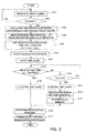
- the equalization controller 30 monitors a voltage of each unit cell 11 by receiving the voltage from the voltage sensors 20. As shown in step S101 in FIG. 2 , the controller 50 receives an ON/OFF signal from the ignition switch 61 and transmits the signal to the equalization controller 30. As shown in step S102 in FIG. 2 , the equalization controller 30 determines whether or not the ignition switch 61 is OFF.
- the equalization controller 30 When the ignition switch 61 is OFF, the equalization controller 30 recognizes that the system relay 63 is OFF, so the connection between the battery pack 10 and the load 62 is disconnected. Then, as shown in step S103 in FIG. 2 , the equalization controller 30 starts calculating a time period required for the equalization process and setting the equalization process time.
- each unit cell 11 is fully charged up to the upper limit of the capacity, which is voltage V 1 for all the unit cells as shown at point p in FIG. 3 .
- V 1 voltage
- each unit cell 11 discharges along the discharge characteristic curve, resulting in a decrease in voltage.
- the discharge curves are assumed to be identical for sake of explanation.
- curves a and b should be identical, they are illustrated as two lines here for sake of explanation.
- Discharge electric currents of respective unit cells 11 are different.
- a discharge electric current of one unit cell 11a is I 1 (A)
- a discharge electric current of another unit cell 11b is I 2 (A)
- I 1 (A) a discharge electric current of another unit cell 11b
- I 1 (A) a discharge electric current of another unit cell 11b
- the discharge electric current I 2 (A) of unit cell 11b is larger than the discharge electric current I 1 (A) of the other unit cell 11a for ⁇ I. Therefore, as shown in FIG.
- the unit cell 11a discharges Ah 1 (ampere hour) from point p to point q shown in a solid line a for time T, while the unit cell 11b discharges Ah 2 (ampere hour) from point p to point r shown in a dash-dot line b. Therefore, the unit cell 11b discharges more than the unit cell 11a for the discharged current amount difference ⁇ Ah.
- SOC remaining capacity
- the ON/OFF switch 42 of the unit discharge circuit 43 is turned ON, after a vehicle is stopped and the discharge from the battery pack 10 to the load 62 is stopped, for the unit cell 11 whose voltage is higher than the average voltage of the unit cells 11 so as to flow a minute equalization discharge electric current I 3 through a discharge resistor 41 to cause discharge from this unit cell with the higher voltage. In this way, voltage equalization is performed for each unit cell 11.
- the total discharged current amount of the unit cell 11a becomes Ah 2 , which is equal to the total discharged current amount of the unit cell 11b. Accordingly, the difference in the remaining capacity (SOC) and voltage can be eliminated.
- the equalization controller 30 starts a step of setting an equalization process time when the ignition switch 61 of an electrically-driven vehicle is turned OFF to stop the vehicle such that the battery pack 10 is disconnected from the load 62.
- the equalization controller 30 calculates a time period An required for an equalization process for each unit cell 11.
- the ignition switch 61 is turned ON each time to start the electrically-driven vehicle, while the ignition switch 61 is turned OFF each time to stop the electrically-driven vehicle. Therefore, the OFF of the ignition switch 61 (IG OFF) for the current time is referred to as "n-th IG OFF" in FIG. 2 .
- the equalization controller 30 calculates a time period Am n required for an equalization process for an m-th unit cell 11 m for the current time (n-th time) from the following equation.
- Am n ⁇ Im n / I 3 x T n
- T n represents a time period (in hours) starting when the ignition switch 61 is turned ON for the n-th time until the ignition switch 61 is turned OFF for the n-th time
- ⁇ Im n is a difference between an electric current discharged from the m-th unit cell 11 m during that period and a reference discharge current of the unit cells 11.
- the difference may be an electric current difference between the electric current discharged from the m-th unit cell 11 m during that period and the average discharged electric current of the unit cells 11 m .
- the difference in a discharged electric current may be an electric current difference between the minimum discharged electric current of the unit cells 11 and the electric current discharged from the m-th unit cell 11 m .
- These values ⁇ Im an and ⁇ Im bn can be stored as a map for each unit cell 11 in the control data 36 of the equalization controller 30.
- step S104 in FIG. 2 the equalization controller 30 reads out, from the memory stack 37, the remaining time period Sm n-1 of the equalization process of the m-th unit cell 11 m performed after the previous (n - 1 time) OFF of the ignition switch 61 described below. Then, as shown in step S105 in FIG. 2 , the equalization controller 30 adds the remaining time period Sm n-1 to the time period Am n required for the current equalization process of the m-th unit cell 11 m obtained above to calculate a setting of the current (n-th time) equalization processing time Am n * of the m-th unit cell 11 m by the following equation.
- Am n * Am n + Sm n - 1
- the equalization controller 30 completes the setting step of the equalization processing time when calculating the setting of the equalization processing time Am n * (where m is 1 to the number of unit cells) of each unit cell 11 m based on Equation 7.
- the equalization controller 30 After completing the setting of the equalization processing time, the equalization controller 30 starts the step of the equalization process as shown in step S106 in FIG. 2 .
- the equalization process is performed, for example, on a unit cell 11 whose setting of the equalization processing time A n * is positive, on all of unit cells 11 when the maximum negative value is set as a reference value for the equalization processing time setting A n *, or only on unit cells 11 whose setting of the equalization processing time A n * is higher than a certain value set as a reference setting A s * of the equalization processing time.
- the description below is provided for an equalization process applied to a unit cell whose setting of the equalization processing time A n * is positive.
- the equalization controller 30 turns ON the respective ON/Off switch 42 provided in parallel with each m-th unit cell 11 m whose setting of the equalization processing time Am n * is positive, in order to discharge electric power stored in the unit cell 11 m through each discharge resistor 41 to thereby reduce the voltage of the unit cell 11 m . Further, as shown in step S107 in FIG. 2 , the equalization controller 30 starts counting time t (count time step) during which the ON/OFF switch 42 is ON and the equalization process is actually performed.
- the equalization controller 30 finishes the equalization process of the unit cell 11 m by turning OFF the ON/OFF switch 42 corresponding to the unit cell 11 m .
- the equalization controller 30 finishes the equalization process when the count time t exceeds each setting of the equalization processing time Am n *.
- the equalization controller 30 turns each switch 23 OFF to stop electric power supply to the respective op-amp 22. Further, the equalization controller 30 outputs a signal, to the controller 50, indicating that the equalization process has been completed.
- step S111 in FIG. 2 in response to receipt of the equalization process complete signal from the equalization controller 30, the controller 50 outputs an instruction to turn the power supply switch 56 OFF.
- the power supply switch 56 is turned OFF in accordance with this instruction, whereby the electric power supply to the equalization controller 30 is stopped.
- step S112 the equalization controller 30 stops the time count as shown in step 113 in FIG. 2 , and stores, in the memory stack 37, the counted time tc obtained at the stop; that is, the time period in which the equalization process has been actually performed. Then, as shown in step S114 in FIG.
- the equalization controller 30 calculates, as a remaining time period Sm n , a time difference between the counted time tc obtained when the ignition switch 61 is turned ON and the setting of the equalization processing time Am n * for the m-th unit cell 11 m in the equalization process whose setting of the equalization processing time Am n * is positive based on Equation 8 shown below, and stores the obtained value in the memory stack 37 as shown in step 115 in FIG. 2 .
- Sm n Am n * - tc
- the equalization controller 30 stores the remaining time period Sm n of the unit cells 11 m if the remaining time period Sm n is positive in the m-th memory stack 37 for the unit cell 11 m .
- This remaining time period Sm n is read out from the memory stack 37 in order to calculate a setting of the equalization processing time Am n+1 * when the ignition switch 61 is turned OFF next time (n + 1 time), and then added to the time period Am n+1 required for the equalization process as shown in the following equation.
- the remaining time period Sm n is carried over sequentially to the next and later setting of the equalization processing time, it is possible to avoid the voltage difference and variations of the remaining capacities (SOC) among unit cells 11 from being accumulated and becoming larger due to the equalization process performed only for a time period less than the full time period required for the equalization process.
- the equalization controller 30 After storing the remaining time period Sm n in the memory stack 37, the equalization controller 30 stops the equalization process as shown in step S110 in FIG. 2 . Then, the equalization controller 30 turns each switch 23 OFF to stop electric power supply to each op-amp 22. Further, the equalization controller 30 outputs a signal, to the controller 50, indicating that the equalization process has been completed. Upon receipt of this equalization process complete signal from the equalization controller 30, the controller 50 outputs an instruction to turn the power supply switch 56 OFF as shown in step S111 in FIG. 2 . The power supply switch 56 is turned OFF in accordance with this instruction and the electric power supply to the equalization controller 30 is stopped.
- the vehicle battery-pack equalization system 100 performs an equalization process by setting an equalization processing time for each unit cell 11 m depending on variation of discharged electric current from the unit cell 11 m . Therefore, because it is possible to avoid each unit cell 11 m from discharging more than necessary, the electric current consumed during the equalization process can be reduced.
- a vehicle battery-pack equalization system 100 because the remaining time period Sm n is carried over to the next and later setting of the equalization processing time if an equalization process is interrupted during the process by the ignition switch 61 which is turned ON before the time period Am n required for the equalization process elapses, it is possible to avoid a voltage difference and a variety of remaining capacities (SOC) from being accumulated and becoming larger. Furthermore, because it is also possible to avoid the situation that some of the unit cells 11 easily reach the upper or lower limit of the cell voltage, the usage width of the battery pack 10 can be larger, thereby avoiding shortening of the running distance of electrically-driven vehicle.
- the voltage sensors 20 are described to sense a difference between the average voltage of the unit cells 11 and a voltage of each unit cell 11.
- the voltage sensors 20 may directly measure a voltage of each unit cell 11 to input the measured voltage to the equalization controller 30.
- the equalization controller 30 may calculate a time period A n required for an equalization process of each unit cell 11 based on the voltage of each unit cell 11 to set each setting of the equalization processing time A n *.
Landscapes
- Engineering & Computer Science (AREA)
- Power Engineering (AREA)
- Mechanical Engineering (AREA)
- Sustainable Energy (AREA)
- Sustainable Development (AREA)
- Transportation (AREA)
- Life Sciences & Earth Sciences (AREA)
- Manufacturing & Machinery (AREA)
- Chemical & Material Sciences (AREA)
- Chemical Kinetics & Catalysis (AREA)
- Electrochemistry (AREA)
- General Chemical & Material Sciences (AREA)
- Electric Propulsion And Braking For Vehicles (AREA)
- Secondary Cells (AREA)
- Charge And Discharge Circuits For Batteries Or The Like (AREA)
Abstract
Description
- The present invention relates to a system and method for equalizing a voltage of each of two or more cells connected in series in a battery pack.
- Recently, electric vehicles driven by an electric motor and hybrid vehicles driven by both an engine and electric motor have come into use. Such electrically-driven vehicles often use, as a power supply, a battery pack in which two or more nickel hydride or lithium ion secondary cells serving as unit cells are connected in series. In such a battery pack, as charging and discharging are repeated, a voltage variation at both ends of unit cells may be caused depending on a charged state (remaining capacity, or state of charge (SOC)) of each unit cell. If charging and discharging are continued with the voltage variation left unremoved, it may become easier for some unit cells to reach the upper or lower limit of cell voltage, resulting in a reduced usable range of the battery pack and shorter travel distance of the electrically-driven vehicle.
- Therefore, it is suggested that equalization of a voltage at both ends of unit cells be started when an ignition switch of a vehicle is turned OFF with a recognition that unit cells are in equilibrium and free from polarization (For example, see Patent Document 1).
Patent Document 1 discloses that the equalization of unit cells is accomplished by repeating, for a predetermined period, moving charges to a capacitor from a unit cell having a voltage at both ends higher than any other unit cells, and then moving charges from the capacitor to a unit cell having a voltage at both ends lower than any other unit cells. - Further, electric power for operation is consumed in an equalization circuit which senses battery characteristics of unit cells to force an overcharged unit cell to consume, as required, electric power in order to equalize the unit cells. Therefore, it is suggested that, when a predetermined time elapses after the running of the vehicle with a battery pack is stopped, electric power to be supplied to an equalization circuit is stopped in order to reduce electric power consumption by such equalization circuit (for example, refer to Patent Document 2).
Patent Document 2 discloses that equalization is performed slowly for a long period of time (about a few hours to one day) and stopped after a predetermined time elapses.Patent Document 2 further describes that the predetermined time to perform equalization is changed in accordance with an instruction from a user or ambient temperature of the vehicle. - When equalization of unit cells is performed with an ignition switch of a vehicle being turned OFF, some electric power from the electric source for the vehicle is consumed. Therefore, in order to reduce the electric power required for the equalization process, it is suggested that a temperature variation in a battery pack is sensed in order to avoid the equalization process of the unit cells when the sensed temperature variation is within a predetermined range (for example, Patent Document 3).
Patent Document 3 further describes that a predetermined time interval to perform an equalization process is set in a timer such that the voltage state of a battery pack is monitored in order to determine whether or not discharge for equalization is necessary; and that an equalization process is performed when the discharge for equalization is determined necessary. -
- Patent Document 1:
JP 2006-246646A - Patent Document 2:
JP 2008-054416A - Patent Document 3:
JP 2007-325458A - As described in
Patent Documents Patent Document 1, because equalization of unit cells is performed with an ignition switch turned OFF, if the ignition switch is turned ON before the predetermined time elapses, the next charging or discharging operation is performed before the current equalization of unit cells has been completed. Therefore, there has been an occasion that a voltage variation of unit cells is accumulated due to uncompleted equalizations of unit cells. In the conventional art described inPatent Document 3, a voltage state of a battery pack is monitored at every time period set in a timer to perform an equalization process if necessary. There is a problem that because the time period set in the timer is an invariable time period, more electric power than necessary may be consumed if the set time period is long. - An object of the present invention is to reduce electric power consumption required for an equalization process in a vehicle battery-pack equalization system.
- A vehicle battery-pack equalization system according to the present invention is characterized by a system that equalizes a voltage or a remaining capacity (SOC) of each of a plurality of cells connected in series in a battery pack mounted on a vehicle by discharging each of the plurality of cells, wherein equalization processing time of each of the cells is set to a time period which is obtained by multiplying a discharge time period of the battery pack immediately before an equalization process by a ratio of difference of an electric current discharged from each of the cells with respect to an equalization discharge electric current.
- In a vehicle battery-pack equalization system according to the present invention, preferably, when the equalization process is interrupted during the equalization process, the equalization processing time of each of the cells for a next equalization process is set to a time period which is obtained by adding a discharge time period of the battery pack immediately before the next equalization process multiplied by a ratio of difference of an electric current discharged from each of the cells with respect to the equalization discharge electric current and a difference between an actual equalization processing time at a previous equalization process and a setting of the equalization processing time for the previous equalization process.
- Further, in the vehicle battery-pack equalization system according to the present invention, preferably, the vehicle includes an ignition switch that starts and stops the vehicle, and in response to turning OFF of the ignition switch, setting of the equalization processing time is started, and the equalization process is started after the equalization processing time is set. Also, preferably, when the ignition switch is turned ON before the set equalization processing time elapses, the equalization process is interrupted.
- A vehicle battery-pack equalization method according to the present invention is characterized by a method that equalizes a voltage or a remaining capacity (SOC) of each of a plurality of cells connected in series in a battery pack mounted on a vehicle by discharging each of the plurality of cells, wherein an equalization process is started after setting an equalization processing time of each of the cells to a time period which is obtained by multiplying a discharge time period of the battery pack immediately before the equalization process by a ratio of difference of an electric current discharged from each of the cells with respect to an equalization discharge electric current.
- In a vehicle battery-pack equalization method according to the present invention, preferably, when the equalization process is interrupted during the equalization process, the equalization processing time of each of the cells for a next equalization process is set to a time period which is obtained by adding a discharge time period of the battery pack immediately before the next equalization process multiplied by a ratio of difference of an electric current discharged from each of the cells with respect to the equalization discharge electric current and a difference between an actual equalization processing time at a previous equalization process and a setting of the equalization processing time for the previous equalization process.
- In a vehicle battery-pack equalization method according to the present invention, preferably, the vehicle includes an ignition switch that starts and stops the vehicle, and in response to turning OFF of the ignition switch, setting of the equalization processing time is started. Also, preferably, when the ignition switch is turned ON before the set equalization processing time elapses, the equalization process is interrupted.
- The present invention achieves an advantage that electric power consumption required for an equalization process can be reduced in a vehicle battery-pack equalization system.
-
-
FIG. 1 is a schematic diagram which shows a configuration of a vehicle battery-pack equalization system according to an embodiment of the present invention. -
FIG. 2 is a flowchart which shows operations of a vehicle battery-pack equalization system according to the embodiment. -
FIG. 3 is an explanatory graph which shows discharge characteristics of unit cells according to the embodiment. - An embodiment according to the present invention is described below by reference to the drawings. Although, in the description below, the
battery pack 10 to which the equalization process is applied is described asunit cells 11 of nickel hydride or lithium ion secondary cells connected in series as a high-voltage battery, unit cells of other types may be combined. In such a case, each of theunit cells 11 corresponds to each of the cells defined inClaim 1. Further, thebattery pack 10 may be formed by two or more battery blocks connected in series, each of which includes two or more unit cells connected in series. In such a case, each battery block corresponds to each of the cells defined inClaim 1. - As shown in
FIG. 1 , a vehicle battery-pack equalization system 100 according to an embodiment of the present invention includesvoltage sensors 20 for measuring a voltage of eachunit cell 11 of abattery pack 10 in which two ormore unit cells 11 are connected in series; anequalization circuit 40 for equalizing a voltage of eachunit cell 11; and anequalization controller 30 for outputting an instruction on the operation of theequalization circuit 40 in accordance with an input from thevoltage sensors 20. It should be noted that, inFIG. 1 , dash-dot lines represent signal lines. - The
battery pack 10 is a high-voltage battery formed by connecting, in series, two ormore unit cells 11 of nickel hydride or lithium ion secondary cell. Each end of thebattery pack 10 is connected, via an inverter or the like, to aload 62 such as a vehicle driving motor. Further, asystem relay 63 is provided between theload 62 and thebattery pack 10 for disconnecting the connection between theload 62 and thebattery pack 10. - Each of
voltage sensors 20 for detecting a voltage of eachunit cell 11 includes a voltage divider resistor 21 which is connected in parallel to eachunit cell 11, and an op-amp 22 which is connected between a negative side of the respective voltage divider resistor 21 and a negative side of therespective unit cell 11. All the voltage divider resistors 21 have the same resistance and are arranged in series in relation to each other. The two ends of each voltage divider resistor 21 are respectively connected to a plus-sideelectrical path 12 and a minus-sideelectrical path 13 of thebattery pack 10. An output of each op-amp 22 is connected to theequalization controller 30 via an interface (not shown) such that the signal is input to theequalization controller 30. A voltage at both ends of each voltage divider resistor 21 is an average voltage of theunit cells 11 which can be obtained by dividing the overall voltage of thebattery pack 10 by the number ofunit cells 11. Each op-amp 22 outputs a voltage difference between a voltage of therespective unit cell 11 and the average voltage of theunit cells 11. Further, each op-amp 22 is configured to be driven by electric power supplied, via aswitch 23, from therespective unit cell 11 from which the op-amp 22 senses the voltage difference. Eachswitch 23 is connected to theequalization controller 30 and is configured to be turned ON and OFF in accordance with an instruction from theequalization controller 30. - In the
equalization circuit 40,unit discharge circuits 43, each of which includes adischarge resistor 41 and an ON/OFF switch 42 connected in series with thedischarge resistor 41, are connected in series in the same number as the unit cells. The ends of theequalization circuit 40 are respectively connected to the plus-sideelectrical path 12 and the minus-sideelectrical path 13 of thebattery pack 10. The two ends of eachunit discharge circuit 43 are connected to a plus-side end and a minus-side end of eachunit cell 11 via arespective connection line 14. Eachunit discharge circuit 43 is arranged to be in parallel with thecorresponding unit cell 11. Further, each ON/OFF switch 42 of eachunit discharge circuit 43 is connected to theequalization controller 30 via an interface (not shown) such that each ON/OFF switch is turned ON/OFF in accordance with an instruction from theequalization controller 30. - The
equalization controller 30 is a computer which includes aCPU 31 for processing signals and amemory 32. Thememory 32 includes an equalization processingtime setting unit 33 for setting a time period for performing an equalization process which equalizes a voltage amongunit cells 11; anEqualization processing unit 34 for performing the equalization process for the set time period; atime counter 35 for counting the time period in which the equalization process is performed;control data 36 which include data such as discharge characteristics of eachunit cell 11; and amemory stack 37 for storing a remaining time period for the equalization process of eachunit cell 11, described below. - An electrically-driven vehicle on which the vehicle battery-
pack equalization system 100 according to the present embodiment is mounted includes acontroller 50 for controlling ON and OFF of a power supply of the electrically-driven vehicle and electric power supplied to theload 62, and apower supply 54 for supplying electric power for driving theequalization controller 30. Provided with an electricpower supply line 55 for supplying electric power from thepower supply 54 to theequalization controller 30 is apower supply switch 56 which disconnects a connection between thepower supply 54 and theequalization controller 30. Further, anignition switch 61 is provided with the electrically-driven vehicle for starting and stopping the vehicle. - The
controller 50 is a computer which includes aCPU 51 for processing signals and amemory 52 in which control programs and data are stored. Thecontroller 50 is configured to be connected with theequalization controller 30 to exchange signals and data therebetween. Thepower supply switch 56, thesystem relay 63, and theload 62 are connected to thecontroller 50 via respective interfaces (not shown) and configured to be operated in accordance with an instruction from thecontroller 50. Further, theignition switch 61 is connected to thecontroller 50 via an interface (not shown) such that a signal indicating whether a driver has turned ON or OFF theignition switch 61 is input to thecontroller 50. - Operations in the embodiment having the above configuration are described below by referring to
FIGs. 2 and3 . While the electrically-driven vehicle is running, thesystem relay 63 is ON and electric power is supplied from thebattery pack 10 to theload 62. Further, with thepower supply switch 56 and switch 23 turned ON, theequalization controller 30 monitors a voltage of eachunit cell 11 by receiving the voltage from thevoltage sensors 20. As shown in step S101 inFIG. 2 , thecontroller 50 receives an ON/OFF signal from theignition switch 61 and transmits the signal to theequalization controller 30. As shown in step S102 inFIG. 2 , theequalization controller 30 determines whether or not theignition switch 61 is OFF. When theignition switch 61 is OFF, theequalization controller 30 recognizes that thesystem relay 63 is OFF, so the connection between thebattery pack 10 and theload 62 is disconnected. Then, as shown in step S103 inFIG. 2 , theequalization controller 30 starts calculating a time period required for the equalization process and setting the equalization process time. - Here, by referring to
FIG. 3 , the description below shows an example of voltage change of eachunit cell 11 when the electrically-driven vehicle is running with both theignition switch 61 andsystem relay 63 being ON. At the start of running of the electrically-driven vehicle, eachunit cell 11 is fully charged up to the upper limit of the capacity, which is voltage V1 for all the unit cells as shown at point p inFIG. 3 . When the electrically-driven vehicle starts running in this state, eachunit cell 11 discharges along the discharge characteristic curve, resulting in a decrease in voltage. Although the actual discharge curves of therespective unit cells 11 may be different, here the discharge curves are assumed to be identical for sake of explanation. Although curves a and b should be identical, they are illustrated as two lines here for sake of explanation. Discharge electric currents ofrespective unit cells 11 are different. Here, it is assumed that a discharge electric current of one unit cell 11a is I1 (A), while a discharge electric current of another unit cell 11b is I2 (A), which is larger than the I1 (A). When electric power is discharged from thebattery pack 10 to theload 62 or the like for the purpose of running the electrically-driven vehicle, electric power is discharged from eachunit cell 11 for the amount of the discharged electric current multiplied by a time period. Because the discharge time period T (time period in which theignition switch 61 is ON) is identical for unit cells 11a and 11b, the discharged current amounts Ah1 and Ah2 of the unit cells 11a and 11b can be obtained by the following equations:

Where the unit of the discharged current amount is ampere hour. The discharge electric current I2 (A) of unit cell 11b is larger than the discharge electric current I1 (A) of the other unit cell 11a for ΔI. Therefore, as shown inFIG. 3 , the unit cell 11a discharges Ah1 (ampere hour) from point p to point q shown in a solid line a for time T, while the unit cell 11b discharges Ah2 (ampere hour) from point p to point r shown in a dash-dot line b. Therefore, the unit cell 11b discharges more than the unit cell 11a for the discharged current amount difference ΔAh.
Therefore, the remaining capacity (SOC) becomes lower for that amount, resulting in variation in remaining capacities (SOC) of the unit cells 11a and 11b. Accordingly, variations appear in the voltages of these unit cells, such as voltages V2 and V3. - There is another difference besides such a discharged electric current difference ΔId between unit cells 11a, 11b. Each
unit cell 11 supplies a drive current to the respective op-amp 22 in order to enable monitoring of the voltage of theunit cell 11. Because there is a variation ΔIe also in this driving current of each op-amp 22, the discharge electric current from eachunit cell 11 varies for the amount of discharged electric current variation ΔId of eachunit cell 11 which occurs when discharging from thebattery pack 10 as a whole, added with the electric current variation ΔIe consumed for monitoring the voltage of therespective unit cell 11. Due to this discharged electric current variation (ΔI =ΔId + ΔIe), a variation occurs in the remaining capacity (SOC) and voltage of eachunit cell 11 when thebattery pack 10 is discharged for a time period T. - When a difference exists in remaining capacity (SOC) or voltage among
unit cells 11 as described above, the ON/OFF switch 42 of theunit discharge circuit 43 is turned ON, after a vehicle is stopped and the discharge from thebattery pack 10 to theload 62 is stopped, for theunit cell 11 whose voltage is higher than the average voltage of theunit cells 11 so as to flow a minute equalization discharge electric current I3 through adischarge resistor 41 to cause discharge from this unit cell with the higher voltage. In this way, voltage equalization is performed for eachunit cell 11. When the unit cell 11a is discharged through thedischarge resistor 41 as described above for the difference ΔAh between the discharged current amount Ah1 of the unit cell 11a and the discharged current amount Ah2 of the unit cell 11b, the total discharged current amount of the unit cell 11a becomes Ah2, which is equal to the total discharged current amount of the unit cell 11b. Accordingly, the difference in the remaining capacity (SOC) and voltage can be eliminated. Thus, the time period Te required for the equalization process of unit cells 11a and 11b is obtained as follows:
Therefore, the time period Te required for the equalization process can be obtained by multiplying the discharge time period T from thebattery pack 10 immediately before an equalization process by a ratio of difference ΔI of electric current discharged from therespective unit cell 11 with respect to an equalization discharge electric current I3. Accordingly, the time period Te becomes proportional to the discharge time period T of thebattery pack 10. - The
equalization controller 30 starts a step of setting an equalization process time when theignition switch 61 of an electrically-driven vehicle is turned OFF to stop the vehicle such that thebattery pack 10 is disconnected from theload 62. First, as shown in step S103 inFIG. 2 , theequalization controller 30 calculates a time period An required for an equalization process for eachunit cell 11. Theignition switch 61 is turned ON each time to start the electrically-driven vehicle, while theignition switch 61 is turned OFF each time to stop the electrically-driven vehicle. Therefore, the OFF of the ignition switch 61 (IG OFF) for the current time is referred to as "n-th IG OFF" inFIG. 2 . Theequalization controller 30 calculates a time period Amn required for an equalization process for an m-th unit cell 11m for the current time (n-th time) from the following equation.
Where Tn represents a time period (in hours) starting when theignition switch 61 is turned ON for the n-th time until theignition switch 61 is turned OFF for the n-th time; and ΔImn is a difference between an electric current discharged from the m-th unit cell 11m during that period and a reference discharge current of theunit cells 11. For example, the difference may be an electric current difference between the electric current discharged from the m-th unit cell 11m during that period and the average discharged electric current of theunit cells 11m. Alternatively, by setting the minimum discharged electric current of theunit cells 11 as a reference, the difference in a discharged electric current may be an electric current difference between the minimum discharged electric current of theunit cells 11 and the electric current discharged from the m-th unit cell 11m. The discharged electric current difference ΔImn of the m-th unit cell 11m from the reference discharge electric current is a sum of an electric current difference ΔIman of the m-th unit cell 11m from the reference discharge electric current when supplying electric power from thebattery pack 10 to theload 62 and an electric current difference ΔImbn between the electric current consumed for monitoring a voltage of therespective unit cell 11 and the reference electric current; that, is, ΔImn = ΔIman + ΔImbn. These values ΔIman and ΔImbn can be stored as a map for eachunit cell 11 in thecontrol data 36 of theequalization controller 30. - Further, the
equalization controller 30 may obtain, from thevoltage sensors 20, a voltage difference between a voltage of the m-th unit cell 11m when theignition switch 61 is turned OFF and the average voltage of theunit cells 11. Then, based on this voltage difference and the discharge electric current curve included in thecontrol data 36, theequalization controller 30 may obtain a discharged current amount difference ΔAhm between the discharged current amount of the m-th unit cell 11m and the average discharged current amount ofunit cells 11. Theequalization controller 30 may calculate a time period Amn required for an equalization process of the m-th unit cell 11m based on the following equation.
- Next, as shown in step S104 in
FIG. 2 , theequalization controller 30 reads out, from thememory stack 37, the remaining time period Smn-1 of the equalization process of the m-th unit cell 11m performed after the previous (n - 1 time) OFF of theignition switch 61 described below. Then, as shown in step S105 inFIG. 2 , theequalization controller 30 adds the remaining time period Smn-1 to the time period Amn required for the current equalization process of the m-th unit cell 11m obtained above to calculate a setting of the current (n-th time) equalization processing time Amn* of the m-th unit cell 11m by the following equation.
Theequalization controller 30 completes the setting step of the equalization processing time when calculating the setting of the equalization processing time Amn* (where m is 1 to the number of unit cells) of eachunit cell 11m based on Equation 7. - After completing the setting of the equalization processing time, the
equalization controller 30 starts the step of the equalization process as shown in step S106 inFIG. 2 . The equalization process is performed, for example, on aunit cell 11 whose setting of the equalization processing time An* is positive, on all ofunit cells 11 when the maximum negative value is set as a reference value for the equalization processing time setting An*, or only onunit cells 11 whose setting of the equalization processing time An* is higher than a certain value set as a reference setting As* of the equalization processing time. The description below is provided for an equalization process applied to a unit cell whose setting of the equalization processing time An* is positive. - The
equalization controller 30 turns ON the respective ON/Off switch 42 provided in parallel with each m-th unit cell 11m whose setting of the equalization processing time Amn* is positive, in order to discharge electric power stored in theunit cell 11m through eachdischarge resistor 41 to thereby reduce the voltage of theunit cell 11m. Further, as shown in step S107 inFIG. 2 , theequalization controller 30 starts counting time t (count time step) during which the ON/OFF switch 42 is ON and the equalization process is actually performed. When the count time t for the m-th unit cell 11m exceeds the setting of the equalization processing time Amn*, theequalization controller 30 finishes the equalization process of theunit cell 11m by turning OFF the ON/OFF switch 42 corresponding to theunit cell 11m. As shown in step S110 inFIG. 2 , for all thetarget unit cells 11 whose setting of the equalization processing time Amn* is positive, theequalization controller 30 finishes the equalization process when the count time t exceeds each setting of the equalization processing time Amn*. Theequalization controller 30 turns eachswitch 23 OFF to stop electric power supply to the respective op-amp 22. Further, theequalization controller 30 outputs a signal, to thecontroller 50, indicating that the equalization process has been completed. As shown in step S111 inFIG. 2 , in response to receipt of the equalization process complete signal from theequalization controller 30, thecontroller 50 outputs an instruction to turn thepower supply switch 56 OFF. Thepower supply switch 56 is turned OFF in accordance with this instruction, whereby the electric power supply to theequalization controller 30 is stopped. - On the other hand, when a driver turns the
ignition switch 61 ON during the equalization process, a signal is input, to thecontroller 50, indicating that theignition switch 61 has been turned ON. Then, thecontroller 50 sends anignition switch 61 ON signal to theequalization controller 30. In response to receipt of this signal indicating that theignition switch 61 has been turned ON as shown in step S112, theequalization controller 30 stops the time count as shown in step 113 inFIG. 2 , and stores, in thememory stack 37, the counted time tc obtained at the stop; that is, the time period in which the equalization process has been actually performed. Then, as shown in step S114 inFIG. 2 , theequalization controller 30 calculates, as a remaining time period Smn, a time difference between the counted time tc obtained when theignition switch 61 is turned ON and the setting of the equalization processing time Amn* for the m-th unit cell 11m in the equalization process whose setting of the equalization processing time Amn* is positive based on Equation 8 shown below, and stores the obtained value in thememory stack 37 as shown in step 115 inFIG. 2 .
It should be noted that, with theunit cells 11m whose remaining time period Smn is negative, the equalization processing time for theunit cell 11m has elapsed and thus the equalization has been completed. On the other hand, with theunit cells 11m whose remaining time period Smn is positive, the equalization processing time for theunit cell 11m has not elapsed and thus the equalization has not been completed. Theequalization controller 30 stores the remaining time period Smn of theunit cells 11m if the remaining time period Smn is positive in the m-th memory stack 37 for theunit cell 11m. This remaining time period Smn is read out from thememory stack 37 in order to calculate a setting of the equalization processing time Amn+1* when theignition switch 61 is turned OFF next time (n + 1 time), and then added to the time period Amn+1 required for the equalization process as shown in the following equation.
Further, the remaining time period Smn-1, obtained in a similar manner, of the equalization process performed after theignition switch 61 is turned OFF for the previous time (n-1 time) is added to the time Amn required for equalization process for the current time (n-th time) when setting the equalization processing time for the current time (n-th time) as shown in Equation 7 as described above. When theignition switch 61 is turned ON and an equalization process of m-th unit cell 11m is interrupted in this way during the process before the time Amn required for equalization process for theunit cell 11m elapses, the remaining time period Smn is carried over sequentially to the next and later setting of the equalization processing time, it is possible to avoid the voltage difference and variations of the remaining capacities (SOC) amongunit cells 11 from being accumulated and becoming larger due to the equalization process performed only for a time period less than the full time period required for the equalization process. - After storing the remaining time period Smn in the
memory stack 37, theequalization controller 30 stops the equalization process as shown in step S110 inFIG. 2 . Then, theequalization controller 30 turns eachswitch 23 OFF to stop electric power supply to each op-amp 22. Further, theequalization controller 30 outputs a signal, to thecontroller 50, indicating that the equalization process has been completed. Upon receipt of this equalization process complete signal from theequalization controller 30, thecontroller 50 outputs an instruction to turn thepower supply switch 56 OFF as shown in step S111 inFIG. 2 . Thepower supply switch 56 is turned OFF in accordance with this instruction and the electric power supply to theequalization controller 30 is stopped. - As described above, the vehicle battery-
pack equalization system 100 according to the embodiment of the present invention performs an equalization process by setting an equalization processing time for eachunit cell 11m depending on variation of discharged electric current from theunit cell 11m. Therefore, because it is possible to avoid eachunit cell 11m from discharging more than necessary, the electric current consumed during the equalization process can be reduced. Further, in a vehicle battery-pack equalization system 100 according to the embodiment of the present invention, because the remaining time period Smn is carried over to the next and later setting of the equalization processing time if an equalization process is interrupted during the process by theignition switch 61 which is turned ON before the time period Amn required for the equalization process elapses, it is possible to avoid a voltage difference and a variety of remaining capacities (SOC) from being accumulated and becoming larger. Furthermore, because it is also possible to avoid the situation that some of theunit cells 11 easily reach the upper or lower limit of the cell voltage, the usage width of thebattery pack 10 can be larger, thereby avoiding shortening of the running distance of electrically-driven vehicle. - In the embodiments described above, the
voltage sensors 20 are described to sense a difference between the average voltage of theunit cells 11 and a voltage of eachunit cell 11. However, thevoltage sensors 20 may directly measure a voltage of eachunit cell 11 to input the measured voltage to theequalization controller 30. Then, theequalization controller 30 may calculate a time period An required for an equalization process of eachunit cell 11 based on the voltage of eachunit cell 11 to set each setting of the equalization processing time An*. - 10 battery pack, 11 unit cell, 11mm-th unit cell, 12 plus-side electrical path, 13 minus-side electrical path, 14 connection line, 20 voltage sensor, 21 voltage divider resistor, 22 op-amp, 23 switch, 30 equalization controller, 32 memory, 33 equalization processing time setting unit, 34 equalization processing unit, 35 time counter, 36 control data, 37 memory stack, 40 equalization circuit, 41 discharge resistor, 42 ON/OFF switch, 43 unit discharge circuit, 50 controller, 52 memory, 54 power supply, 55 power supply line, 56 power supply switch, 61 ignition switch, 62 load, 63 system relay, 100 vehicle battery-pack equalization system, Amn time period required for equalization process for m-th unit cell, Amn* setting of equalization processing time for m-th unit cell, An time required for equalization process, An* setting of equalization processing time, As* reference setting of equalization processing time, Smn remaining time period of equalization process for m-th unit cell.
Claims (8)
- A vehicle battery-pack equalization system that equalizes a voltage or a remaining capacity (SOC) of each of a plurality of cells connected in series in a battery pack mounted on a vehicle by discharging each of the plurality of cells,
wherein equalization processing time of each of the cells is set to a time period which is obtained by multiplying a discharge time period of the battery pack immediately before an equalization process by a ratio of difference of an electric current discharged from the respective cell with respect to an equalization discharge electric current. - The vehicle battery-pack equalization system according to claim 1, wherein
when the equalization process is interrupted during the equalization process, the equalization processing time of each of the cells for a next equalization process is set to a time period which is obtained by adding
a discharge time period of the batterypack immediately before the next equalization process multiplied by a ratio of difference of an electric current discharged from the respective cell with respect to the equalization discharge electric current and
a difference between an actual equalization processing time at a previous equalization process and a setting of the equalization processing time for the previous equalization process. - The vehicle battery-pack equalization system according to claim 1, wherein
the vehicle includes an ignition switch that starts and stops the vehicle, and
in response to turning OFF of the ignition switch, setting of the equalization processing time is started, and the equalization process is started after the equalization processing time is set. - The vehicle battery-pack equalization system according to claim 2, wherein
the vehicle includes an ignition switch that starts and stops the vehicle, and
when the ignition switch is turned ON before the set equalization processing time elapses, the equalization process is interrupted. - A vehicle battery-pack equalization method that equalizes a voltage or a remaining capacity (SOC) of each of a plurality of cells connected in series in a battery pack mounted on a vehicle by discharging each of the plurality of cells,
wherein an equalization process is started after setting an equalization processing time of each of the cells to a time period which is obtained by multiplying a discharge time period of the battery pack immediately before the equalization process by a ratio of difference of an electric current discharged from the respective cell with respect to an equalization discharge electric current. - The vehicle battery-pack equalization method according to claim 5, wherein
when the equalization process is interrupted during the equalization process, the equalization processing time of each of the cells for a next equalization process is set to a time period which is obtained by adding
a discharge time period of the battery pack immediately before the next equalization process multiplied by a ratio of difference of an electric current discharged from the respective cell with respect to the equalization discharge electric current and
a difference between an actual equalization processing time at a previous equalization process and a setting of the equalization processing time for the previous equalization process. - The vehicle battery-pack equalization method according to claim 5, wherein
the vehicle includes an ignition switch that starts and stops the vehicle, and
in response to turning OFF of the ignition switch, setting of the equalization processing time is started. - The vehicle battery-pack equalization method according to claim 6, wherein
the vehicle includes an ignition switch that starts and stops the vehicle, and
when the ignition switch is turned ON before the set equalization processing time elapses, the equalization process is interrupted.
Applications Claiming Priority (1)
| Application Number | Priority Date | Filing Date | Title |
|---|---|---|---|
| PCT/JP2010/059759 WO2011155034A1 (en) | 2010-06-09 | 2010-06-09 | Vehicle battery-pack equalization system and vehicle battery-pack equalization method |
Publications (4)
| Publication Number | Publication Date |
|---|---|
| EP2582010A1 true EP2582010A1 (en) | 2013-04-17 |
| EP2582010A8 EP2582010A8 (en) | 2013-08-07 |
| EP2582010A4 EP2582010A4 (en) | 2015-01-07 |
| EP2582010B1 EP2582010B1 (en) | 2017-10-04 |
Family
ID=45097665
Family Applications (1)
| Application Number | Title | Priority Date | Filing Date |
|---|---|---|---|
| EP10852874.6A Active EP2582010B1 (en) | 2010-06-09 | 2010-06-09 | Vehicle battery-pack equalization system and vehicle battery-pack equalization method |
Country Status (6)
| Country | Link |
|---|---|
| US (1) | US8957636B2 (en) |
| EP (1) | EP2582010B1 (en) |
| JP (1) | JP5316709B2 (en) |
| KR (1) | KR101424908B1 (en) |
| CN (1) | CN102918738B (en) |
| WO (1) | WO2011155034A1 (en) |
Cited By (2)
| Publication number | Priority date | Publication date | Assignee | Title |
|---|---|---|---|---|
| CN109435777A (en) * | 2017-08-31 | 2019-03-08 | 比亚迪股份有限公司 | Battery equalization system, vehicle, battery equalization method and storage medium |
| EP3675312A4 (en) * | 2017-08-31 | 2020-07-01 | BYD Company Limited | Battery balancing system, vehicle, battery balancing method, and storage medium |
Families Citing this family (23)
| Publication number | Priority date | Publication date | Assignee | Title |
|---|---|---|---|---|
| JP5562180B2 (en) | 2010-08-27 | 2014-07-30 | 日立アプライアンス株式会社 | Axial gap type rotating electrical machine |
| JP5998454B2 (en) * | 2011-11-07 | 2016-09-28 | ソニー株式会社 | Control device, control method, and control system |
| DE102012213926A1 (en) * | 2012-08-07 | 2014-02-13 | Robert Bosch Gmbh | Battery module, battery management system, system for supplying a drive of a machine suitable for generating torque with electrical energy and motor vehicle |
| JP5704146B2 (en) * | 2012-10-22 | 2015-04-22 | トヨタ自動車株式会社 | Power storage system |
| JP6036849B2 (en) * | 2012-12-27 | 2016-11-30 | トヨタ自動車株式会社 | In-vehicle control device |
| US8901888B1 (en) | 2013-07-16 | 2014-12-02 | Christopher V. Beckman | Batteries for optimizing output and charge balance with adjustable, exportable and addressable characteristics |
| CN105556786A (en) * | 2013-09-27 | 2016-05-04 | 日本电气株式会社 | Power-storage-cell management device, power-storage cell, method for managing power-storage cell, and program |
| CN103730931B (en) * | 2013-12-20 | 2016-11-23 | 惠州市亿能电子有限公司 | A kind of equalization methods being applicable to motor vehicle driven by mixed power battery system |
| KR101726927B1 (en) * | 2014-11-21 | 2017-04-13 | 주식회사 엘지화학 | Apparatus and method for battery module operation |
| CN107005072B (en) * | 2015-02-23 | 2020-11-24 | 皇家飞利浦有限公司 | Charger device for battery-backed power supply |
| KR102475482B1 (en) * | 2015-11-18 | 2022-12-09 | 삼성전자주식회사 | Method and apparatus of controlling battery, and battery pack enabling the method |
| JP6361643B2 (en) * | 2015-12-15 | 2018-07-25 | 横河電機株式会社 | Energy storage service system |
| WO2017132529A1 (en) * | 2016-01-27 | 2017-08-03 | The University Of Toledo | A bilevel equalizer for battery cell charge management |
| CN110015179B (en) * | 2017-08-31 | 2023-01-06 | 比亚迪股份有限公司 | Battery equalization method, system, vehicle, storage medium and electronic device |
| KR102202614B1 (en) * | 2017-09-19 | 2021-01-12 | 주식회사 엘지화학 | Battery management system and a battery pack including the same |
| CN108183518B (en) * | 2017-11-30 | 2020-03-06 | 宁德时代新能源科技股份有限公司 | Battery pack balance control method and device and balance control equipment |
| JP7085428B2 (en) * | 2018-07-10 | 2022-06-16 | 株式会社半導体エネルギー研究所 | Battery protection circuit, power storage device, and electrical equipment |
| CN109274160A (en) * | 2018-11-28 | 2019-01-25 | 中车株洲电力机车有限公司 | A kind of battery equalisation method, system and rail traffic vehicles |
| JP7481147B2 (en) | 2020-03-31 | 2024-05-10 | Fdk株式会社 | Battery voltage equalizer |
| CN113625167B (en) * | 2020-05-08 | 2024-04-12 | 郑州宇通集团有限公司 | Evaluation method for equalization effect of battery management system |
| KR102532062B1 (en) * | 2020-12-10 | 2023-05-12 | 현대모비스 주식회사 | Apparatus for managing battery cell and method thereof |
| KR20230024068A (en) | 2021-08-11 | 2023-02-20 | 김수연 | Customized backrest chair |
| KR20230055714A (en) | 2021-10-19 | 2023-04-26 | 현대자동차주식회사 | Billing system and method for based on available capacity of vehicle battery |
Citations (2)
| Publication number | Priority date | Publication date | Assignee | Title |
|---|---|---|---|---|
| US20060103351A1 (en) * | 2004-11-18 | 2006-05-18 | Denso Corporation | Battery pack manager |
| JP2007244058A (en) * | 2006-03-07 | 2007-09-20 | Nissan Motor Co Ltd | Capacity adjusting device of battery pack |
Family Cites Families (14)
| Publication number | Priority date | Publication date | Assignee | Title |
|---|---|---|---|---|
| JP4567109B2 (en) * | 1998-11-24 | 2010-10-20 | パナソニック株式会社 | Secondary battery charge / discharge control method |
| US7508165B2 (en) * | 2004-10-19 | 2009-03-24 | Denso Corporation | Cell voltage equalization apparatus for combined battery pack including circuit driven by power supplied by the combined battery pack |
| JP2006246646A (en) | 2005-03-04 | 2006-09-14 | Yazaki Corp | Equalization method and its device |
| JP2007325458A (en) | 2006-06-02 | 2007-12-13 | Toyota Motor Corp | Vehicular battery pack uniformizing system |
| JP4872496B2 (en) * | 2006-07-06 | 2012-02-08 | 日産自動車株式会社 | Battery detection device |
| JP2008054416A (en) | 2006-08-24 | 2008-03-06 | Toyota Motor Corp | Battery pack equalizer and vehicle mounted with the battery pack |
| JP2009011022A (en) | 2007-06-26 | 2009-01-15 | Nissan Motor Co Ltd | Capacity adjusting device and capacity adjusting method of battery pack |
| US20090079391A1 (en) * | 2007-09-25 | 2009-03-26 | O2Micro Inc. | Systems and methods for cell balancing |
| WO2009076418A1 (en) * | 2007-12-11 | 2009-06-18 | Antonio Trigiani | Battery management system |
| JP2010088194A (en) * | 2008-09-30 | 2010-04-15 | Nissan Motor Co Ltd | Device and method for adjusting capacity of battery pack |
| CN101404347A (en) * | 2008-10-24 | 2009-04-08 | 中国移动通信集团甘肃有限公司 | Accumulator charging management method and apparatus |
| CN101692502B (en) * | 2009-09-25 | 2011-08-17 | 深圳市航盛电子股份有限公司 | Battery management system |
| JP2012113856A (en) * | 2010-11-22 | 2012-06-14 | Toyota Motor Corp | Method of replacing power supply stack, control device, and control program |
| JP5375927B2 (en) * | 2011-11-02 | 2013-12-25 | 株式会社豊田自動織機 | Battery equalization apparatus and method |
-
2010
- 2010-06-09 US US13/575,238 patent/US8957636B2/en active Active
- 2010-06-09 JP JP2012519167A patent/JP5316709B2/en active Active
- 2010-06-09 CN CN201080064537.4A patent/CN102918738B/en active Active
- 2010-06-09 EP EP10852874.6A patent/EP2582010B1/en active Active
- 2010-06-09 KR KR1020127026984A patent/KR101424908B1/en active IP Right Grant
- 2010-06-09 WO PCT/JP2010/059759 patent/WO2011155034A1/en active Application Filing
Patent Citations (2)
| Publication number | Priority date | Publication date | Assignee | Title |
|---|---|---|---|---|
| US20060103351A1 (en) * | 2004-11-18 | 2006-05-18 | Denso Corporation | Battery pack manager |
| JP2007244058A (en) * | 2006-03-07 | 2007-09-20 | Nissan Motor Co Ltd | Capacity adjusting device of battery pack |
Non-Patent Citations (2)
| Title |
|---|
| None * |
| See also references of WO2011155034A1 * |
Cited By (5)
| Publication number | Priority date | Publication date | Assignee | Title |
|---|---|---|---|---|
| CN109435777A (en) * | 2017-08-31 | 2019-03-08 | 比亚迪股份有限公司 | Battery equalization system, vehicle, battery equalization method and storage medium |
| EP3675312A4 (en) * | 2017-08-31 | 2020-07-01 | BYD Company Limited | Battery balancing system, vehicle, battery balancing method, and storage medium |
| EP3678276A4 (en) * | 2017-08-31 | 2020-09-09 | BYD Company Limited | Battery balancing system, vehicle, battery balancing method, and storage medium |
| CN109435777B (en) * | 2017-08-31 | 2021-02-23 | 比亚迪股份有限公司 | Battery equalization system, vehicle, battery equalization method, and storage medium |
| US11571981B2 (en) | 2017-08-31 | 2023-02-07 | Byd Company Limited | Battery equalization system, vehicle, battery equalization method and storage medium |
Also Published As
| Publication number | Publication date |
|---|---|
| EP2582010A4 (en) | 2015-01-07 |
| CN102918738B (en) | 2015-01-28 |
| KR20130007613A (en) | 2013-01-18 |
| EP2582010B1 (en) | 2017-10-04 |
| CN102918738A (en) | 2013-02-06 |
| JPWO2011155034A1 (en) | 2013-08-01 |
| EP2582010A8 (en) | 2013-08-07 |
| JP5316709B2 (en) | 2013-10-16 |
| US8957636B2 (en) | 2015-02-17 |
| KR101424908B1 (en) | 2014-08-01 |
| WO2011155034A1 (en) | 2011-12-15 |
| US20130069596A1 (en) | 2013-03-21 |
Similar Documents
| Publication | Publication Date | Title |
|---|---|---|
| US8957636B2 (en) | Vehicle battery-pack equalization system and vehicle battery-pack equalization method | |
| JP5567956B2 (en) | Cell voltage equalization device for multiple assembled batteries | |
| EP3267552B1 (en) | Battery control device and vehicle system | |
| JP3867581B2 (en) | Assembled battery system | |
| EP3279679B1 (en) | Battery control device and electric vehicle system | |
| EP2847026B1 (en) | Electrical storage system and equalizing method | |
| US8493031B2 (en) | Equalization device, battery system and electric vehicle including the same, equalization processing program, and equalization processing method | |
| CN107817450B (en) | Storage element pack, management device, SOC estimation method, medium, and panel system | |
| US9755281B2 (en) | Method for connecting battery cells in a battery, battery, and monitoring device | |
| JP5719236B2 (en) | Secondary battery control device | |
| JP5397013B2 (en) | Battery control device | |
| CN103457003A (en) | Charge control device for secondary battery, charge control method for secondary battery | |
| WO2008065910A1 (en) | Accumulator failure detecting device, accumulator failure detecting method, accumulator failure detecting program, and computer-readable recording medium containing the accumulator failure detecting program | |
| CN114194041A (en) | Method for estimating a full charge time of a battery, powertrain controller and electric vehicle | |
| JP3453821B2 (en) | Battery remaining capacity measurement device | |
| WO2011145255A1 (en) | Battery control device and vehicle | |
| JP5131533B2 (en) | Battery charge / discharge control method and charge / discharge control apparatus | |
| WO2016200319A1 (en) | A method and a monitoring unit for monitoring a battery system | |
| EP3872920A1 (en) | Battery control device | |
| JP4961861B2 (en) | Battery detection device | |
| JP5525199B2 (en) | Battery capacity control device for battery pack | |
| JPH10106635A (en) | Battery pack condition detecting method | |
| JP2000235065A (en) | Battery control apparatus | |
| JP2021058071A (en) | Method and device for setting charging rate | |
| JP2014085118A (en) | Electricity storage system and abnormality discrimination method |
Legal Events
| Date | Code | Title | Description |
|---|---|---|---|
| PUAI | Public reference made under article 153(3) epc to a published international application that has entered the european phase |
Free format text: ORIGINAL CODE: 0009012 |
|
| 17P | Request for examination filed |
Effective date: 20120831 |
|
| AK | Designated contracting states |
Kind code of ref document: A1 Designated state(s): AL AT BE BG CH CY CZ DE DK EE ES FI FR GB GR HR HU IE IS IT LI LT LU LV MC MK MT NL NO PL PT RO SE SI SK SM TR |
|
| RIN1 | Information on inventor provided before grant (corrected) |
Inventor name: OCHIAI, KIYOE |
|
| RIN1 | Information on inventor provided before grant (corrected) |
Inventor name: OCHIAI, KIYOE |
|
| DAX | Request for extension of the european patent (deleted) | ||
| A4 | Supplementary search report drawn up and despatched |
Effective date: 20141210 |
|
| RIC1 | Information provided on ipc code assigned before grant |
Ipc: H02J 7/02 20060101AFI20141204BHEP Ipc: H01M 10/44 20060101ALI20141204BHEP Ipc: B60L 3/00 20060101ALI20141204BHEP |
|
| REG | Reference to a national code |
Ref country code: DE Ref legal event code: R079 Ref document number: 602010045820 Country of ref document: DE Free format text: PREVIOUS MAIN CLASS: H02J0007020000 Ipc: H02J0007000000 |
|
| GRAP | Despatch of communication of intention to grant a patent |
Free format text: ORIGINAL CODE: EPIDOSNIGR1 |
|
| RIC1 | Information provided on ipc code assigned before grant |
Ipc: H02J 7/00 20060101AFI20170331BHEP Ipc: H01M 10/44 20060101ALI20170331BHEP Ipc: H02J 7/02 20160101ALI20170331BHEP Ipc: B60L 3/00 20060101ALI20170331BHEP |
|
| INTG | Intention to grant announced |
Effective date: 20170426 |
|
| GRAS | Grant fee paid |
Free format text: ORIGINAL CODE: EPIDOSNIGR3 |
|
| GRAA | (expected) grant |
Free format text: ORIGINAL CODE: 0009210 |
|
| AK | Designated contracting states |
Kind code of ref document: B1 Designated state(s): AL AT BE BG CH CY CZ DE DK EE ES FI FR GB GR HR HU IE IS IT LI LT LU LV MC MK MT NL NO PL PT RO SE SI SK SM TR |
|
| REG | Reference to a national code |
Ref country code: GB Ref legal event code: FG4D |
|
| REG | Reference to a national code |
Ref country code: CH Ref legal event code: EP |
|
| REG | Reference to a national code |
Ref country code: AT Ref legal event code: REF Ref document number: 934861 Country of ref document: AT Kind code of ref document: T Effective date: 20171015 |
|
| REG | Reference to a national code |
Ref country code: IE Ref legal event code: FG4D |
|
| REG | Reference to a national code |
Ref country code: DE Ref legal event code: R096 Ref document number: 602010045820 Country of ref document: DE |
|
| REG | Reference to a national code |
Ref country code: NL Ref legal event code: MP Effective date: 20171004 |
|
| REG | Reference to a national code |
Ref country code: LT Ref legal event code: MG4D |
|
| REG | Reference to a national code |
Ref country code: AT Ref legal event code: MK05 Ref document number: 934861 Country of ref document: AT Kind code of ref document: T Effective date: 20171004 |
|
| REG | Reference to a national code |
Ref country code: DE Ref legal event code: R084 Ref document number: 602010045820 Country of ref document: DE |
|
| PG25 | Lapsed in a contracting state [announced via postgrant information from national office to epo] |
Ref country code: NL Free format text: LAPSE BECAUSE OF FAILURE TO SUBMIT A TRANSLATION OF THE DESCRIPTION OR TO PAY THE FEE WITHIN THE PRESCRIBED TIME-LIMIT Effective date: 20171004 |
|
| PG25 | Lapsed in a contracting state [announced via postgrant information from national office to epo] |
Ref country code: ES Free format text: LAPSE BECAUSE OF FAILURE TO SUBMIT A TRANSLATION OF THE DESCRIPTION OR TO PAY THE FEE WITHIN THE PRESCRIBED TIME-LIMIT Effective date: 20171004 Ref country code: FI Free format text: LAPSE BECAUSE OF FAILURE TO SUBMIT A TRANSLATION OF THE DESCRIPTION OR TO PAY THE FEE WITHIN THE PRESCRIBED TIME-LIMIT Effective date: 20171004 Ref country code: SE Free format text: LAPSE BECAUSE OF FAILURE TO SUBMIT A TRANSLATION OF THE DESCRIPTION OR TO PAY THE FEE WITHIN THE PRESCRIBED TIME-LIMIT Effective date: 20171004 Ref country code: LT Free format text: LAPSE BECAUSE OF FAILURE TO SUBMIT A TRANSLATION OF THE DESCRIPTION OR TO PAY THE FEE WITHIN THE PRESCRIBED TIME-LIMIT Effective date: 20171004 Ref country code: NO Free format text: LAPSE BECAUSE OF FAILURE TO SUBMIT A TRANSLATION OF THE DESCRIPTION OR TO PAY THE FEE WITHIN THE PRESCRIBED TIME-LIMIT Effective date: 20180104 |
|
| PG25 | Lapsed in a contracting state [announced via postgrant information from national office to epo] |
Ref country code: BG Free format text: LAPSE BECAUSE OF FAILURE TO SUBMIT A TRANSLATION OF THE DESCRIPTION OR TO PAY THE FEE WITHIN THE PRESCRIBED TIME-LIMIT Effective date: 20180104 Ref country code: LV Free format text: LAPSE BECAUSE OF FAILURE TO SUBMIT A TRANSLATION OF THE DESCRIPTION OR TO PAY THE FEE WITHIN THE PRESCRIBED TIME-LIMIT Effective date: 20171004 Ref country code: GR Free format text: LAPSE BECAUSE OF FAILURE TO SUBMIT A TRANSLATION OF THE DESCRIPTION OR TO PAY THE FEE WITHIN THE PRESCRIBED TIME-LIMIT Effective date: 20180105 Ref country code: IS Free format text: LAPSE BECAUSE OF FAILURE TO SUBMIT A TRANSLATION OF THE DESCRIPTION OR TO PAY THE FEE WITHIN THE PRESCRIBED TIME-LIMIT Effective date: 20180204 Ref country code: AT Free format text: LAPSE BECAUSE OF FAILURE TO SUBMIT A TRANSLATION OF THE DESCRIPTION OR TO PAY THE FEE WITHIN THE PRESCRIBED TIME-LIMIT Effective date: 20171004 Ref country code: HR Free format text: LAPSE BECAUSE OF FAILURE TO SUBMIT A TRANSLATION OF THE DESCRIPTION OR TO PAY THE FEE WITHIN THE PRESCRIBED TIME-LIMIT Effective date: 20171004 |
|
| REG | Reference to a national code |
Ref country code: DE Ref legal event code: R097 Ref document number: 602010045820 Country of ref document: DE |
|
| PG25 | Lapsed in a contracting state [announced via postgrant information from national office to epo] |
Ref country code: DK Free format text: LAPSE BECAUSE OF FAILURE TO SUBMIT A TRANSLATION OF THE DESCRIPTION OR TO PAY THE FEE WITHIN THE PRESCRIBED TIME-LIMIT Effective date: 20171004 Ref country code: EE Free format text: LAPSE BECAUSE OF FAILURE TO SUBMIT A TRANSLATION OF THE DESCRIPTION OR TO PAY THE FEE WITHIN THE PRESCRIBED TIME-LIMIT Effective date: 20171004 Ref country code: SK Free format text: LAPSE BECAUSE OF FAILURE TO SUBMIT A TRANSLATION OF THE DESCRIPTION OR TO PAY THE FEE WITHIN THE PRESCRIBED TIME-LIMIT Effective date: 20171004 Ref country code: CZ Free format text: LAPSE BECAUSE OF FAILURE TO SUBMIT A TRANSLATION OF THE DESCRIPTION OR TO PAY THE FEE WITHIN THE PRESCRIBED TIME-LIMIT Effective date: 20171004 |
|
| PLBE | No opposition filed within time limit |
Free format text: ORIGINAL CODE: 0009261 |
|
| STAA | Information on the status of an ep patent application or granted ep patent |
Free format text: STATUS: NO OPPOSITION FILED WITHIN TIME LIMIT |
|
| PG25 | Lapsed in a contracting state [announced via postgrant information from national office to epo] |
Ref country code: SM Free format text: LAPSE BECAUSE OF FAILURE TO SUBMIT A TRANSLATION OF THE DESCRIPTION OR TO PAY THE FEE WITHIN THE PRESCRIBED TIME-LIMIT Effective date: 20171004 Ref country code: PL Free format text: LAPSE BECAUSE OF FAILURE TO SUBMIT A TRANSLATION OF THE DESCRIPTION OR TO PAY THE FEE WITHIN THE PRESCRIBED TIME-LIMIT Effective date: 20171004 Ref country code: IT Free format text: LAPSE BECAUSE OF FAILURE TO SUBMIT A TRANSLATION OF THE DESCRIPTION OR TO PAY THE FEE WITHIN THE PRESCRIBED TIME-LIMIT Effective date: 20171004 Ref country code: RO Free format text: LAPSE BECAUSE OF FAILURE TO SUBMIT A TRANSLATION OF THE DESCRIPTION OR TO PAY THE FEE WITHIN THE PRESCRIBED TIME-LIMIT Effective date: 20171004 |
|
| 26N | No opposition filed |
Effective date: 20180705 |
|
| PG25 | Lapsed in a contracting state [announced via postgrant information from national office to epo] |
Ref country code: SI Free format text: LAPSE BECAUSE OF FAILURE TO SUBMIT A TRANSLATION OF THE DESCRIPTION OR TO PAY THE FEE WITHIN THE PRESCRIBED TIME-LIMIT Effective date: 20171004 |
|
| REG | Reference to a national code |
Ref country code: CH Ref legal event code: PL |
|
| GBPC | Gb: european patent ceased through non-payment of renewal fee |
Effective date: 20180609 |
|
| REG | Reference to a national code |
Ref country code: BE Ref legal event code: MM Effective date: 20180630 |
|
| REG | Reference to a national code |
Ref country code: IE Ref legal event code: MM4A |
|
| PG25 | Lapsed in a contracting state [announced via postgrant information from national office to epo] |
Ref country code: MC Free format text: LAPSE BECAUSE OF FAILURE TO SUBMIT A TRANSLATION OF THE DESCRIPTION OR TO PAY THE FEE WITHIN THE PRESCRIBED TIME-LIMIT Effective date: 20171004 Ref country code: LU Free format text: LAPSE BECAUSE OF NON-PAYMENT OF DUE FEES Effective date: 20180609 |
|
| PG25 | Lapsed in a contracting state [announced via postgrant information from national office to epo] |
Ref country code: CH Free format text: LAPSE BECAUSE OF NON-PAYMENT OF DUE FEES Effective date: 20180630 Ref country code: LI Free format text: LAPSE BECAUSE OF NON-PAYMENT OF DUE FEES Effective date: 20180630 Ref country code: FR Free format text: LAPSE BECAUSE OF NON-PAYMENT OF DUE FEES Effective date: 20180630 Ref country code: GB Free format text: LAPSE BECAUSE OF NON-PAYMENT OF DUE FEES Effective date: 20180609 Ref country code: IE Free format text: LAPSE BECAUSE OF NON-PAYMENT OF DUE FEES Effective date: 20180609 |
|
| PG25 | Lapsed in a contracting state [announced via postgrant information from national office to epo] |
Ref country code: BE Free format text: LAPSE BECAUSE OF NON-PAYMENT OF DUE FEES Effective date: 20180630 |
|
| PG25 | Lapsed in a contracting state [announced via postgrant information from national office to epo] |
Ref country code: MT Free format text: LAPSE BECAUSE OF NON-PAYMENT OF DUE FEES Effective date: 20180609 |
|
| PG25 | Lapsed in a contracting state [announced via postgrant information from national office to epo] |
Ref country code: TR Free format text: LAPSE BECAUSE OF FAILURE TO SUBMIT A TRANSLATION OF THE DESCRIPTION OR TO PAY THE FEE WITHIN THE PRESCRIBED TIME-LIMIT Effective date: 20171004 |
|
| PG25 | Lapsed in a contracting state [announced via postgrant information from national office to epo] |
Ref country code: HU Free format text: LAPSE BECAUSE OF FAILURE TO SUBMIT A TRANSLATION OF THE DESCRIPTION OR TO PAY THE FEE WITHIN THE PRESCRIBED TIME-LIMIT; INVALID AB INITIO Effective date: 20100609 Ref country code: PT Free format text: LAPSE BECAUSE OF FAILURE TO SUBMIT A TRANSLATION OF THE DESCRIPTION OR TO PAY THE FEE WITHIN THE PRESCRIBED TIME-LIMIT Effective date: 20171004 |
|
| PG25 | Lapsed in a contracting state [announced via postgrant information from national office to epo] |
Ref country code: CY Free format text: LAPSE BECAUSE OF FAILURE TO SUBMIT A TRANSLATION OF THE DESCRIPTION OR TO PAY THE FEE WITHIN THE PRESCRIBED TIME-LIMIT Effective date: 20171004 Ref country code: MK Free format text: LAPSE BECAUSE OF NON-PAYMENT OF DUE FEES Effective date: 20171004 |
|
| PG25 | Lapsed in a contracting state [announced via postgrant information from national office to epo] |
Ref country code: AL Free format text: LAPSE BECAUSE OF FAILURE TO SUBMIT A TRANSLATION OF THE DESCRIPTION OR TO PAY THE FEE WITHIN THE PRESCRIBED TIME-LIMIT Effective date: 20171004 |
|
| P01 | Opt-out of the competence of the unified patent court (upc) registered |
Effective date: 20230427 |
|
| PGFP | Annual fee paid to national office [announced via postgrant information from national office to epo] |
Ref country code: DE Payment date: 20240502 Year of fee payment: 15 |