EP2581504A1 - Construction machine - Google Patents
Construction machine Download PDFInfo
- Publication number
- EP2581504A1 EP2581504A1 EP11792452.2A EP11792452A EP2581504A1 EP 2581504 A1 EP2581504 A1 EP 2581504A1 EP 11792452 A EP11792452 A EP 11792452A EP 2581504 A1 EP2581504 A1 EP 2581504A1
- Authority
- EP
- European Patent Office
- Prior art keywords
- door
- area
- operator
- front pillar
- cab
- Prior art date
- Legal status (The legal status is an assumption and is not a legal conclusion. Google has not performed a legal analysis and makes no representation as to the accuracy of the status listed.)
- Granted
Links
Images

Classifications
-
- E—FIXED CONSTRUCTIONS
- E02—HYDRAULIC ENGINEERING; FOUNDATIONS; SOIL SHIFTING
- E02F—DREDGING; SOIL-SHIFTING
- E02F9/00—Component parts of dredgers or soil-shifting machines, not restricted to one of the kinds covered by groups E02F3/00 - E02F7/00
- E02F9/16—Cabins, platforms, or the like, for drivers
- E02F9/163—Structures to protect drivers, e.g. cabins, doors for cabins; Falling object protection structure [FOPS]; Roll over protection structure [ROPS]
-
- B—PERFORMING OPERATIONS; TRANSPORTING
- B60—VEHICLES IN GENERAL
- B60J—WINDOWS, WINDSCREENS, NON-FIXED ROOFS, DOORS, OR SIMILAR DEVICES FOR VEHICLES; REMOVABLE EXTERNAL PROTECTIVE COVERINGS SPECIALLY ADAPTED FOR VEHICLES
- B60J5/00—Doors
-
- B—PERFORMING OPERATIONS; TRANSPORTING
- B60—VEHICLES IN GENERAL
- B60J—WINDOWS, WINDSCREENS, NON-FIXED ROOFS, DOORS, OR SIMILAR DEVICES FOR VEHICLES; REMOVABLE EXTERNAL PROTECTIVE COVERINGS SPECIALLY ADAPTED FOR VEHICLES
- B60J5/00—Doors
- B60J5/04—Doors arranged at the vehicle sides
- B60J5/0486—Special type
- B60J5/0487—Special type simplified doors related to cabins of, e.g. golf carts, tractors, jeeps, cranes, forklifts, etc.
-
- B—PERFORMING OPERATIONS; TRANSPORTING
- B62—LAND VEHICLES FOR TRAVELLING OTHERWISE THAN ON RAILS
- B62D—MOTOR VEHICLES; TRAILERS
- B62D25/00—Superstructure or monocoque structure sub-units; Parts or details thereof not otherwise provided for
- B62D25/08—Front or rear portions
-
- B—PERFORMING OPERATIONS; TRANSPORTING
- B62—LAND VEHICLES FOR TRAVELLING OTHERWISE THAN ON RAILS
- B62D—MOTOR VEHICLES; TRAILERS
- B62D33/00—Superstructures for load-carrying vehicles
- B62D33/06—Drivers' cabs
-
- B—PERFORMING OPERATIONS; TRANSPORTING
- B62—LAND VEHICLES FOR TRAVELLING OTHERWISE THAN ON RAILS
- B62D—MOTOR VEHICLES; TRAILERS
- B62D33/00—Superstructures for load-carrying vehicles
- B62D33/06—Drivers' cabs
- B62D33/0617—Drivers' cabs for tractors or off-the-road vehicles
-
- E—FIXED CONSTRUCTIONS
- E02—HYDRAULIC ENGINEERING; FOUNDATIONS; SOIL SHIFTING
- E02F—DREDGING; SOIL-SHIFTING
- E02F3/00—Dredgers; Soil-shifting machines
- E02F3/04—Dredgers; Soil-shifting machines mechanically-driven
- E02F3/28—Dredgers; Soil-shifting machines mechanically-driven with digging tools mounted on a dipper- or bucket-arm, i.e. there is either one arm or a pair of arms, e.g. dippers, buckets
- E02F3/30—Dredgers; Soil-shifting machines mechanically-driven with digging tools mounted on a dipper- or bucket-arm, i.e. there is either one arm or a pair of arms, e.g. dippers, buckets with a dipper-arm pivoted on a cantilever beam, i.e. boom
- E02F3/32—Dredgers; Soil-shifting machines mechanically-driven with digging tools mounted on a dipper- or bucket-arm, i.e. there is either one arm or a pair of arms, e.g. dippers, buckets with a dipper-arm pivoted on a cantilever beam, i.e. boom working downwardly and towards the machine, e.g. with backhoes
- E02F3/325—Backhoes of the miniature type
-
- E—FIXED CONSTRUCTIONS
- E02—HYDRAULIC ENGINEERING; FOUNDATIONS; SOIL SHIFTING
- E02F—DREDGING; SOIL-SHIFTING
- E02F9/00—Component parts of dredgers or soil-shifting machines, not restricted to one of the kinds covered by groups E02F3/00 - E02F7/00
- E02F9/16—Cabins, platforms, or the like, for drivers
Definitions
- the present invention relates to a construction machine such as a compact excavator provided with an operator's cab having a door capable of opening and closing an opening surface forming a boarding port.
- the hydraulic excavator forming a compact slewing device as disclosed in Patent Document 1.
- the hydraulic excavator has an undercarriage, an upper structure disposed on the undercarriage, a work device attached to the upper structure, and a cab, that is, an operator's cab, provided on the upper structure and having a door capable of opening and closing an opening surface forming a boarding port.
- the operator's cab has a left front pillar disposed on the work device side, that is, a front pillar, and a center pillar to which the door is attached rotatably, that is, a door mounting pillar.
- the front pillar and the door mounting pillar are provided to put the boarding port therebetween.
- the door consists of two door pieces coupled with each other through a plurality of hinges in order to prevent the operator's cab from protruding outside the essentially requested turning radius of the upper structure which is not larger than the vehicle width in the hydraulic excavator forming a compact slewing device.
- the hinges are attached to edge portions of the respective door pieces provided vertically in a center portion of the whole door consisting of the two door pieces.
- the turning radius of the upper structure would be beyond the aforementioned essentially requested turning radius which is not larger than the vehicle width.
- the slewing of the upper structure might be restricted by the work environment so as to cause troubles in various works performed by means of the work device of the hydraulic excavator forming the compact slewing device.
- Patent Literature 1 JP-A-2006-21753
- the whole door is formed out of two door pieces so that the essentially requested turning radius which is not larger than the vehicle width can be secured.
- a plurality of hinges coupling the two door pieces with each other are provided in the center portion of the whole door, and these hinges are attached to the edge portions of the respective door pieces. Accordingly, it is impossible to secure a good field of view for an operator seated on an operator' s seat in the operator's cab.
- the hinges are required in the center portion of the whole door, the number of parts increases. Thus, the manufacturing cost may increase easily.
- An object of the invention is to provide a construction machine capable of securing a turning radius not larger than the vehicle width, capable of securing a good field of view for an operator seated on an operator's seat, and capable of reducing the number of components.
- a construction machine including an undercarriage, an upper structure disposed on the undercarriage, a work device attached to the upper structure, and an operator's cab provided on the upper structure and having a door capable of opening and closing an opening surface forming a boarding port, the operator's cab including a front pillar and a door mounting pillar which are provided to put the boarding port therebetween, the front pillar being disposed on the work device side, the door being rotatably attached to the door mounting pillar, the construction machine being characterized in that: the door consists of one door piece, and has a flexing portion which is closer to the front pillar than a center portion of the door when the door is in a closed state; and the flexing portion is formed into a shape having a first area which is formed so that, when the door is in a closed state, the first area approaches the opening surface as the first area approaches the front pillar, and a second area which is arranged
- the flexing portion is provided nearer the front pillar than the center portion of the door, and the flexing portion is formed into a shape having a first area which is formed so that when the door is closed, the first area approaches the opening surface forming the boarding port as the first area approaches the front pillar, and a second area which is arranged continuously with the first area and which is formed so that the second area draws away from the aforementioned opening surface as the second area approaches the front pillar.
- the flexing portion is provided nearer the front pillar than the center portion of the door, it is possible to form the center portion of the door to overhang outside the flexing portion. Thus, it is possible to prevent the door from gaining entrance into the operator's cab while securing a large space in the operator's cab.
- the door consists of one door piece, a plurality of hinges and members to which the hinges are attached do not have to be provided in the center portion of the door.
- a good field of view for an operator seated on the operator's seat it is possible to reduce the number of components.
- the door is provided with the flexing portion nearer the front pillar than the center portion, it is possible to secure high rigidity in the flexing portion, and it is therefore possible to improve air tightness when the door is closed.
- the flexing portion is formed into a shape which is disposed substantially inside a turning radius of the upper structure defined to be not larger than a vehicle width of the undercarriage when the door is in a completely open state.
- the flexing portion is formed into a shape in which an end portion of the second area of the flexing portion is located on the turning radius when the door is in a completely open state.
- a recess portion which receives the end portion of the second area of the flexing portion when the door is in a closed state is provided in the front pillar.
- the end portion of the second area of the flexing portion of the door is received in the recess portion of the front pillar when the door is closed. Accordingly, the end portion of the second area of the flexing portion can be prevented frombeing disposed outside the front pillar. This contributes to keeping the turning radius not larger than the vehicle width.
- the construction machine consists of a compact excavator, which is provided with a step for making it easy to get on and off the operator's cab, and a protrusion portion which protrudes outward from the opening surface is provided in a part of the step while a convex portion which covers the protrusion portion of the step when the door is in a closed state is provided in a part of the door.
- the protrusion portion protruding outward from the opening surface forming a boarding port of the operator's cab is provided only in a part of the step.
- the protrusion portion can be provided in the step without changing the outer shell shape of the operator's cab. That is, the dimensions of the shape of the step can be increased without increasing the turning radius.
- the protrusion portion provided in the step is covered with the convex portion provided in a part of the door, so that the whole step including the protrusion portion can be located in the operator's cab. Accordingly, it is possible to prevent fallen snow from being frozen on the step even when the construction machine is placed in a cold district where snow falls.
- a door for opening and closing an opening surface forming a boarding port consists of one door piece, and has a flexing portion provided nearer a front pillar than a center portion of the door when the door is in a closed state.
- the flexing portion is formed into a shape having a first area which is formed so that, when the door is in a closed state, the first area approaches the opening surface as the first area approaches the front pillar, and a second area which is arranged continuously with the first area and nearer the front pillar than the first area and which is formed so that the second area draws away from the opening surface as the second area approaches the front pillar. It is therefore possible to secure a turning radius not larger than the vehicle width without forming a large operator's cab.
- a work device for slewing an upper structure can be driven to perform a desired work without trouble.
- the center portion of the door can be formed to overhang outside the flexing portion.
- a plurality of hinges and members to which the hinges are attached do not have to be provided in the center portion of the door so that it is possible to secure a good field of view for the operator seated on the operator's seat, and the operationality performed by the operator can be improved in comparison with that in the background art.
- Fig. 1 is a side view showing a compact excavator arranged as an embodiment of a construction machine according to the invention.
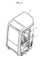
- Fig. 2 is a perspective view showing an operator's cab provided in the compact excavator shown in Fig. 1 .
- the construction machine according to this embodiment is constituted by a compact excavator which is a kind of small-size construction machine.
- the compact excavator has an undercarriage 1 having a pair of left and right crawler belts 1a, an upper structure 2 disposed on the undercarriage 1, and a work device 3 attached to the upper structure 2 so as to be rotatable in an up/down direction.
- the work device 3 includes a boom 3a attached to the upper structure 2, an arm 3b attached to a front end of the boom 3a, and a bucket 3c attached to a front end of the arm 3b.
- An operator's cab 6 accommodating an operator's seat 4 and having a door 5 consisting of one door piece capable of opening and closing an opening surface 16 of a boarding port 20 which will be described later is disposed on the upper structure 2.
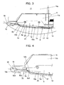
- Fig. 3 is a plan view showing in section a main portion of the operator's cab shown in Fig. 2 when the door is closed.
- Fig. 4 is a main portion enlarged view of Fig. 3 .
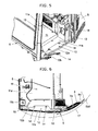
- Fig. 5 is a main portion perspective view showing the operator's cab shown in Fig. 2 when the door is open.
- Fig. 6 is a plan view showing in section a main portion of the operator's cab shown in Fig. 2 when the door is open.
- the compact excavator according to the embodiment is configured so that a protrusion portion 12a protruding outward from the opening surface 16 forming the boarding port 20 of the operator's cab 6 is provided in a part of a step which makes it easy to get on and off the operator's cab 6.
- a floor 11 of the operator's cab 6 includes a flat portion 11a disposed in front of the aforementioned operator's seat 4, and a step portion 11b disposed on the boarding port 20 side.
- the step portion 11b is provided continuously with the flat portion 11a and arranged in a lower position than the flat portion 11a.
- a flange portion 12 forming the same plane as that of the step portion 11b of the floor 11 is provided continuously with the step portion 11b in the operator's cab 6.
- the aforementioned step consists of the step portion 11b of the floor 11 and the flange portion 12.
- the protrusion portion 12a protruding outward from the opening surface 15 forming the boarding port 20 as shown in Fig. 4 is provided in the flange portion 12.
- the flange portion 12 is removably fixed to a frame forming the operator's cab 6, by means of a pair of bolts 14.
- An end surface of a main portion of the protrusion portion 12a provided in the flange portion 12 is, for example, formed into a linear shape in a horizontal plane.
- the operator's cab 6 has a pillar disposed on the work device 3 side, that is, a front pillar 15, and a pillar to which the door 5 is attached rotatably through hinges 18, that is, a door mounting pillar 13.
- the front pillar 15 and the door mounting pillar 13 are provided to put the boarding port 20 therebetween.
- a flexing portion 12b which is formed so that the flexing portion 12b approaches the opening surface 16 forming the boarding port 20 as the flexing portion 12b approaches the front pillar 15 is provided in an end portion of the protrusion portion 12a of the flange portion 12 on the front pillar 15 side.
- a convex portion 5a which covers the protrusion portion 12a provided in the flange portion 12 forming the step when the door 5 is in a closed state is provided in a part of a lower end portion of the door 5.
- a main portion of the convex portion 5a is formed into a flat surface shape in accordance with the linear shape of the end surface of the main portion of the protrusion portion 12a of the flange portion 12.
- the convex portion 5a is, for example, formed by press working for manufacturing the door 5.
- the door 5 has a flexing portion 5b nearer the front pillar 15 than a center portion 21 of the door 5 when the door 5 is in a closed state.
- the flexing portion 5b is formed into a shape having a first area 5b1 formed to extend to a center vicinity 30 of the flexing portion 5b so that, when the door 5 is in a closed state, the first area 5b1 approaches the opening surface 16 of the boardingport 20 as the first area 5b1 approaches the front pillar 15, and a second area 5b2 which is arranged continuously with the first area 5b1 and nearer the front pillar 15 than the first area 5b1 and which is formed so that the second area 5b2 draws away from the opening surface 16 as the second area 5b2 approaches the front pillar 15.
- the flexing portion 5b is formed into a shape which is disposed substantially inside a turning radius 17 of the upper structure 2 defined to be not larger than the vehicle width of the undercarriage 1 when the door 5 is in a completely open state.
- the flexing portion 5b is formed into a shape such that an end portion 5b3 of the second area 5b2 of the flexing portion 5b is located on the turning radius 17 when the door 5 is in a completely open state.
- the flexing portion 5b is formed into a shape such that the end portion 5b3 of the second area 5b2 of the flexing portion 5b is received in a recess portion 15a formed in the front pillar 15 when the door 5 is in a closed state. Further, as shown in Fig. 6 , the flexing portion 5b forms a clearance portion which can prevent the door 5 from interfering with the exterior cover 8 of the upper structure 2 when the door 5 is completely open.
- the turning radius 17 shown in Figs. 4 and 6 is set so that the turning radius 17 can keep a turning radius equivalent to that in a background-art compact excavator as described above, that is, a size not larger than the vehicle width defined by the paired crawler belts 1a of the undercarriage 1.
- an operator may open the door 5, put his/her foot on the step consisting of the step portion 11b of the floor 11 and the flange portion 12 having the protrusion portion 12a, climb on the flat portion 11a of the floor 11, and seat himself/herself on the operator's seat 4, as shown in Figs. 5 and 6 .
- the operator seated on the operator's seat 4 thus operates an operating lever disposed in the operator's cab 6, for example, to drive the work device 3 shown in Fig. 1 .
- a desired work such as a soil excavation work can be carried out.
- the door 5 When the door 5 is completely open, the door 5 is disposed to face the exterior cover 8 of the upper structure 2, as shown in Fig. 6 .
- the door 5 may be closed if occasion demands.
- the operator may leave the operator's seat 4, move from the flat portion 11a of the floor 11 onto the step consisting of the step portion 11b and the flange portion 12, further step off onto the ground where the compact excavator is placed, and then close the door 5, for example, as shown in Figs. 3 and 4 .
- the protrusion portion 12a of the flange portion 12 is covered with the convex portion 5a of the door 5 while the end portion 5b3 of the second area 5b2 of the flexing portion 5b of the door 5 is received in the recess portion 15a of the front pillar 15.
- the end surface of the main portion of the protrusion portion 12a of the flange portion 12 is formed into a linear shape in a horizontal plane, and the main portion of the convex portion 5a of the door 5 is formed into a flat surface shape.
- the end surface of the main portion of the protrusion portion 12a of the flange portion 12 maybe, for example, formed into a curved shape in a horizontal plane or formed into a shape with irregular portions.
- the convex portion 5a of the door 5 may be formed to have a curved surface in a horizontal plane or formed to have a curved surface in a vertical plane.
- the protrusion portion 12a and the convex portion 5a may be formed into various shapes.
- the flexing portion 5b is provided nearer the front pillar 15 than the center portion 21 of the door 5, and the flexing portion 5b is formed into a shape including the first area 5b1 formed so that, when the door 5 is closed, the first area 5b1 approaches the opening surface 16 forming the boarding port 20 as the first area 5b1 approaches the front pillar 15, and the second area 5b2 which is arranged continuously with the first area 5b1 and which is formed so that the second area 5b2 draws away from the aforementioned opening surface 16 as the second area 5b2 approaches the front pillar 15. It is therefore possible to provide the door 5 whose shape does not bring about any change on the basic design of the operator's cab 6.
- the work device 3 for slewing the upper structure 2 can be driven to perform a desired work without any trouble.
- the flexing portion 5b is provided nearer the front pillar 15 than the center portion 21 of the door 5. It is therefore possible to form the center portion 21 of the door 5 to overhang outside the flexing portion 5b. Thus, it is possible to prevent the door 5 from gaining entrance into the operator's cab 6 while securing a large space in the operator's cab 6. This contributes to securing good operationality performed by the operator seated in the operator's cab 6.
- the door 5 consists of one door piece, a plurality of hinges 18 and members to which these hinges 18 are attached do not have to be provided in the center portion 21 of the door 5.
- the operator seated on the operator's seat 4 can secure a good field of view.
- the manufacturing cost can be reduced.
- the door 5 is provided with the flexing portion 5b nearer the front pillar 15 than the center portion 21, it is possible to secure high rigidity in the flexing portion 5b. Accordingly, it is possible to improve air tightness when the door 5 is closed. Thus, it is possible to obtain a highly reliable door structure in the operator's cab 6.
- the flexing portion 5b is formed into a shape which is disposed substantially inside the turning radius 17 of the upper structure 2 defined to be not larger than the vehicle width of the undercarriage 1 when the door 5 is in a completely open state. Accordingly, even when a work is carried out in the state where the door 5 is completely open, the upper structure 2 can be slewed well without being influenced by the flexing portion 5b provided thus. Thus, the work can be carried out.
- the recess portion 15a which receives the end portion 5b3 of the second area 5b2 of the flexing portion 5b when the door 5 is in a closed state is provided in the front pillar 15. Accordingly, the end portion 5b3 of the second area 5b2 of the flexing portion 5b provided in the door 5 is received in the recess portion 15a of the front pillar 15 when the door 5 is closed. Accordingly, the end portion 5b3 of the second area 5b2 can be prevented from being disposed outside the front pillar 15. This contributes to keeping the turning radius 17 not larger than the vehicle width.
- the protrusion portion 12a which protrudes outward from the opening surface 15 forming the boarding port 20 of the operator's cab 6 is provided only in a part of the flange portion 12 forming a step.
- the protrusion portion 12a can be provided in the step without changing the outer shell shape of the operator's cab 6. That is, the dimensions of the shape of the step can be increased without increasing the turning radius 17.
- the upper structure 2 can be slewed to drive the work device 3 so as to perform a desired work without any trouble. At the same time, getting on/off the operator's cab 6 can be performed easily.
- the protrusion portion 12a of the flange portion 12 is covered with the convex portion 5a provided in the door 5, so that the whole step including the protrusion portion 12a can be located in the operator's cab 6. It is therefore possible to prevent fallen snow from being frozen in the step including the protrusion portion 12a even when the compact excavator is placed in a cold district where snow falls. Accordingly, the situation that the door 5 cannot be opened due to the frozen snow can be avoided so that the door 5 can be opened and closed smoothly.
- Apluralityof combinations of the flange portion 12 having the protrusion portion 12a and the door 5 having the convex portion 5a may be taken into account in advance. That is, protrusion portions 12a having different shapes from each other or convex portions 5a having different shapes from each other may be taken into account in advance. It is therefore possible to easily obtain an operator's cab 6 having a combination of a selected flange portion 12 and a selected door 5 without having any change in the basic design of the operator's cab 6.
- the flexing portion 5b of the door 5 forms a clearance portion for preventing interference with the exterior cover 8 forming the upper structure 2. It is therefore possible to suppress damage of the door 5 and damage of the exterior cover 8 when the door 5 is operated to be open. Thus, a highly reliable compact excavator can be obtained.
- the aforementioned embodiment consists of a compact excavator.
- the construction machine according to the invention may be a hydraulic excavator which is larger than the compact excavator.
- the construction machine may be any construction machine different from the hydraulic excavator as long as the construction machine has an upper structure provided on an undercarriage and an openable door provided on the upper structure.
Landscapes
- Engineering & Computer Science (AREA)
- Mechanical Engineering (AREA)
- Mining & Mineral Resources (AREA)
- Civil Engineering (AREA)
- General Engineering & Computer Science (AREA)
- Structural Engineering (AREA)
- Chemical & Material Sciences (AREA)
- Combustion & Propulsion (AREA)
- Transportation (AREA)
- Component Parts Of Construction Machinery (AREA)
- Body Structure For Vehicles (AREA)
Abstract
Description
- The present invention relates to a construction machine such as a compact excavator provided with an operator's cab having a door capable of opening and closing an opening surface forming a boarding port.
- As this type background-art technique, there is a hydraulic excavator forming a compact slewing device as disclosed in
Patent Document 1. The hydraulic excavator has an undercarriage, an upper structure disposed on the undercarriage, a work device attached to the upper structure, and a cab, that is, an operator's cab, provided on the upper structure and having a door capable of opening and closing an opening surface forming a boarding port. The operator's cab has a left front pillar disposed on the work device side, that is, a front pillar, and a center pillar to which the door is attached rotatably, that is, a door mounting pillar. The front pillar and the door mounting pillar are provided to put the boarding port therebetween. - In addition, the door consists of two door pieces coupled with each other through a plurality of hinges in order to prevent the operator's cab from protruding outside the essentially requested turning radius of the upper structure which is not larger than the vehicle width in the hydraulic excavator forming a compact slewing device. The hinges are attached to edge portions of the respective door pieces provided vertically in a center portion of the whole door consisting of the two door pieces.
- If the door were formed out of one door piece to increase the operator's cab, the turning radius of the upper structure would be beyond the aforementioned essentially requested turning radius which is not larger than the vehicle width. Thus, the slewing of the upper structure might be restricted by the work environment so as to cause troubles in various works performed by means of the work device of the hydraulic excavator forming the compact slewing device.
- Patent Literature 1:
JP-A-2006-21753 - According to the background-art technique disclosed in
Patent Document 1, the whole door is formed out of two door pieces so that the essentially requested turning radius which is not larger than the vehicle width can be secured. However, a plurality of hinges coupling the two door pieces with each other are provided in the center portion of the whole door, and these hinges are attached to the edge portions of the respective door pieces. Accordingly, it is impossible to secure a good field of view for an operator seated on an operator' s seat in the operator's cab. In addition, since the hinges are required in the center portion of the whole door, the number of parts increases. Thus, the manufacturing cost may increase easily. - The present invention has been accomplished in consideration of the aforementioned actual situation in the background art. An object of the invention is to provide a construction machine capable of securing a turning radius not larger than the vehicle width, capable of securing a good field of view for an operator seated on an operator's seat, and capable of reducing the number of components.
- In order to attain the foregoing object, according to the present invention, there is provided a construction machine including an undercarriage, an upper structure disposed on the undercarriage, a work device attached to the upper structure, and an operator's cab provided on the upper structure and having a door capable of opening and closing an opening surface forming a boarding port, the operator's cab including a front pillar and a door mounting pillar which are provided to put the boarding port therebetween, the front pillar being disposed on the work device side, the door being rotatably attached to the door mounting pillar, the construction machine being characterized in that: the door consists of one door piece, and has a flexing portion which is closer to the front pillar than a center portion of the door when the door is in a closed state; and the flexing portion is formed into a shape having a first area which is formed so that, when the door is in a closed state, the first area approaches the opening surface as the first area approaches the front pillar, and a second area which is arranged continuously with the first area and nearer the front pillar than the first area and which is formed so that the second area draws away from the opening surface as the second area approaches the front pillar.
- According to the invention configured thus, the flexing portion is provided nearer the front pillar than the center portion of the door, and the flexing portion is formed into a shape having a first area which is formed so that when the door is closed, the first area approaches the opening surface forming the boarding port as the first area approaches the front pillar, and a second area which is arranged continuously with the first area and which is formed so that the second area draws away from the aforementioned opening surface as the second area approaches the front pillar. Accordingly, it is possible to provide a door whose shape does not bring about any change in the basic design of the operator's cab. That is, since it is not necessary to form the operator's cab largely for installing the door, it is possible to secure the turning radius not larger than the vehicle width.
- In addition, since the flexing portion is provided nearer the front pillar than the center portion of the door, it is possible to form the center portion of the door to overhang outside the flexing portion. Thus, it is possible to prevent the door from gaining entrance into the operator's cab while securing a large space in the operator's cab.
- In addition, since the door consists of one door piece, a plurality of hinges and members to which the hinges are attached do not have to be provided in the center portion of the door. Thus, it is possible to secure a good field of view for an operator seated on the operator's seat. In addition, it is possible to reduce the number of components.
- Further, since the door is provided with the flexing portion nearer the front pillar than the center portion, it is possible to secure high rigidity in the flexing portion, and it is therefore possible to improve air tightness when the door is closed.
- In addition, according to the invention, there is provided the aforementioned configuration of the invention characterized in that: the flexing portion is formed into a shape which is disposed substantially inside a turning radius of the upper structure defined to be not larger than a vehicle width of the undercarriage when the door is in a completely open state. According to the invention configured thus, even when a work is carried out in the state where the door is completely open, the upper structure can be slewed well without being influenced by the flexing portion provided thus. Thus, the work can be carried out.
- In addition, according to the invention, there is provided the aforementioned configuration of the invention characterized in that: the flexing portion is formed into a shape in which an end portion of the second area of the flexing portion is located on the turning radius when the door is in a completely open state.
- In addition, according to the invention, there is provided the aforementioned configuration of the invention characterized in that: a recess portion which receives the end portion of the second area of the flexing portion when the door is in a closed state is provided in the front pillar. According to the invention configured thus, the end portion of the second area of the flexing portion of the door is received in the recess portion of the front pillar when the door is closed. Accordingly, the end portion of the second area of the flexing portion can be prevented frombeing disposed outside the front pillar. This contributes to keeping the turning radius not larger than the vehicle width.
- In addition, according to the invention, there is provided the aforementioned configuration of the invention characterized in that: the construction machine consists of a compact excavator, which is provided with a step for making it easy to get on and off the operator's cab, and a protrusion portion which protrudes outward from the opening surface is provided in a part of the step while a convex portion which covers the protrusion portion of the step when the door is in a closed state is provided in a part of the door.
- According to the invention configured thus, the protrusion portion protruding outward from the opening surface forming a boarding port of the operator's cab is provided only in a part of the step. Thus, the protrusion portion can be provided in the step without changing the outer shell shape of the operator's cab. That is, the dimensions of the shape of the step can be increased without increasing the turning radius. In addition, when the door is closed, the protrusion portion provided in the step is covered with the convex portion provided in a part of the door, so that the whole step including the protrusion portion can be located in the operator's cab. Accordingly, it is possible to prevent fallen snow from being frozen on the step even when the construction machine is placed in a cold district where snow falls.
- According to the invention, a door for opening and closing an opening surface forming a boarding port consists of one door piece, and has a flexing portion provided nearer a front pillar than a center portion of the door when the door is in a closed state. The flexing portion is formed into a shape having a first area which is formed so that, when the door is in a closed state, the first area approaches the opening surface as the first area approaches the front pillar, and a second area which is arranged continuously with the first area and nearer the front pillar than the first area and which is formed so that the second area draws away from the opening surface as the second area approaches the front pillar. It is therefore possible to secure a turning radius not larger than the vehicle width without forming a large operator's cab. Thus, according to the invention, a work device for slewing an upper structure can be driven to perform a desired work without trouble.
- In addition, according to the invention, the center portion of the door can be formed to overhang outside the flexing portion. Thus, it is possible to prevent the door from gaining entrance into the operator's cab while securing a large space in the operator's cab. This contributes to securing good operationality for an operator seated in the operator's cab.
- In addition, according to the invention, a plurality of hinges and members to which the hinges are attached do not have to be provided in the center portion of the door so that it is possible to secure a good field of view for the operator seated on the operator's seat, and the operationality performed by the operator can be improved in comparison with that in the background art. In addition, it is possible to reduce the number of components so that it is possible to reduce the manufacturing cost in comparison with that in the background art.
- Further, according to the invention, it is possible to secure high rigidity in the flexing portion, so that it is possible to improve air tightness in comparison with that in the background art when the door is closed, and it is possible to obtain a highly reliable door structure in the operator's cab.
-
- [
Fig. 1 ] A side view showing a compact excavator arranged as an embodiment of a construction machine according to the invention. - [
Fig. 2 ] A perspective view showing an operator's cab provided in the compact excavator shown inFig. 1 . - [
Fig. 3 ] A plan view showing in section a main portion of the operator's cab shown inFig. 2 when a door is closed. - [
Fig. 4 ] A main portion enlarged view ofFig. 3 . - [
Fig. 5 ] A main portion perspective view showing the operator's cab shown inFig. 2 when the door is open. - [
Fig. 6 ] A plan view showing in section a main portion of the operator's cab shown inFig. 2 when the door is open. - An embodiment of a construction machine according to the invention will be describedbelow with reference to the drawings.
-
Fig. 1 is a side view showing a compact excavator arranged as an embodiment of a construction machine according to the invention.Fig. 2 is a perspective view showing an operator's cab provided in the compact excavator shown inFig. 1 . - As shown in these
Figs. 1 and2 , the construction machine according to this embodiment is constituted by a compact excavator which is a kind of small-size construction machine. The compact excavator has anundercarriage 1 having a pair of left andright crawler belts 1a, anupper structure 2 disposed on theundercarriage 1, and awork device 3 attached to theupper structure 2 so as to be rotatable in an up/down direction. Thework device 3 includes aboom 3a attached to theupper structure 2, anarm 3b attached to a front end of theboom 3a, and abucket 3c attached to a front end of thearm 3b. - An operator's
cab 6 accommodating an operator'sseat 4 and having adoor 5 consisting of one door piece capable of opening and closing an openingsurface 16 of aboarding port 20 which will be described later is disposed on theupper structure 2. In addition, anengine 7, amachine room 9 accommodating a not-shown pump etc. and covered with anexterior cover 8, and acounter weight 10 for securing a weight balance are disposed in theupper structure 2. -
Fig. 3 is a plan view showing in section a main portion of the operator's cab shown inFig. 2 when the door is closed.Fig. 4 is a main portion enlarged view ofFig. 3 .Fig. 5 is a main portion perspective view showing the operator's cab shown inFig. 2 when the door is open.Fig. 6 is a plan view showing in section a main portion of the operator's cab shown inFig. 2 when the door is open. - The compact excavator according to the embodiment is configured so that a
protrusion portion 12a protruding outward from the openingsurface 16 forming theboarding port 20 of the operator'scab 6 is provided in a part of a step which makes it easy to get on and off the operator'scab 6. - That is, as shown in
Figs. 3 to 6 , afloor 11 of the operator'scab 6 includes aflat portion 11a disposed in front of the aforementioned operator'sseat 4, and astep portion 11b disposed on theboarding port 20 side. Thestep portion 11b is provided continuously with theflat portion 11a and arranged in a lower position than theflat portion 11a. Aflange portion 12 forming the same plane as that of thestep portion 11b of thefloor 11 is provided continuously with thestep portion 11b in the operator'scab 6. The aforementioned step consists of thestep portion 11b of thefloor 11 and theflange portion 12. Theprotrusion portion 12a protruding outward from the openingsurface 15 forming theboarding port 20 as shown inFig. 4 is provided in theflange portion 12. - The
flange portion 12 is removably fixed to a frame forming the operator'scab 6, by means of a pair ofbolts 14. An end surface of a main portion of theprotrusion portion 12a provided in theflange portion 12 is, for example, formed into a linear shape in a horizontal plane. - As shown in
Figs. 4 and6 , the operator'scab 6 has a pillar disposed on thework device 3 side, that is, afront pillar 15, and a pillar to which thedoor 5 is attached rotatably through hinges 18, that is, adoor mounting pillar 13. Thefront pillar 15 and thedoor mounting pillar 13 are provided to put theboarding port 20 therebetween. As shown inFig. 4 , a flexingportion 12b which is formed so that the flexingportion 12b approaches the openingsurface 16 forming theboarding port 20 as the flexingportion 12b approaches thefront pillar 15 is provided in an end portion of theprotrusion portion 12a of theflange portion 12 on thefront pillar 15 side. - As shown in
Figs. 3 and 4 , aconvex portion 5a which covers theprotrusion portion 12a provided in theflange portion 12 forming the step when thedoor 5 is in a closed state is provided in a part of a lower end portion of thedoor 5. A main portion of theconvex portion 5a is formed into a flat surface shape in accordance with the linear shape of the end surface of the main portion of theprotrusion portion 12a of theflange portion 12. Theconvex portion 5a is, for example, formed by press working for manufacturing thedoor 5. - In addition, according to the embodiment, as shown in
Figs. 3 and 4 , thedoor 5 has a flexingportion 5b nearer thefront pillar 15 than acenter portion 21 of thedoor 5 when thedoor 5 is in a closed state. - As shown in
Fig. 4 , the flexingportion 5b is formed into a shape having a first area 5b1 formed to extend to acenter vicinity 30 of the flexingportion 5b so that, when thedoor 5 is in a closed state, the first area 5b1 approaches the openingsurface 16 of theboardingport 20 as the first area 5b1 approaches thefront pillar 15, and a second area 5b2 which is arranged continuously with the first area 5b1 and nearer thefront pillar 15 than the first area 5b1 and which is formed so that the second area 5b2 draws away from the openingsurface 16 as the second area 5b2 approaches thefront pillar 15. - In addition, as shown in
Figs. 5 and 6 , the flexingportion 5b is formed into a shape which is disposed substantially inside a turningradius 17 of theupper structure 2 defined to be not larger than the vehicle width of theundercarriage 1 when thedoor 5 is in a completely open state. For example, as shown inFig. 6 , the flexingportion 5b is formed into a shape such that an end portion 5b3 of the second area 5b2 of the flexingportion 5b is located on the turningradius 17 when thedoor 5 is in a completely open state. - In addition, as shown in
Fig. 4 , the flexingportion 5b is formed into a shape such that the end portion 5b3 of the second area 5b2 of the flexingportion 5b is received in arecess portion 15a formed in thefront pillar 15 when thedoor 5 is in a closed state. Further, as shown inFig. 6 , the flexingportion 5b forms a clearance portion which can prevent thedoor 5 from interfering with theexterior cover 8 of theupper structure 2 when thedoor 5 is completely open. - The basic outer shell shape of the operator's
cab 6 is not changed. Therefore, the turningradius 17 shown inFigs. 4 and6 is set so that the turningradius 17 can keep a turning radius equivalent to that in a background-art compact excavator as described above, that is, a size not larger than the vehicle width defined by the pairedcrawler belts 1a of theundercarriage 1. - According to the embodiment configured thus, to sit on the operator's
seat 4 in order to perform a work, an operator may open thedoor 5, put his/her foot on the step consisting of thestep portion 11b of thefloor 11 and theflange portion 12 having theprotrusion portion 12a, climb on theflat portion 11a of thefloor 11, and seat himself/herself on the operator'sseat 4, as shown inFigs. 5 and 6 . The operator seated on the operator'sseat 4 thus operates an operating lever disposed in the operator'scab 6, for example, to drive thework device 3 shown inFig. 1 . Thus, a desired work such as a soil excavation work can be carried out. When thedoor 5 is completely open, thedoor 5 is disposed to face theexterior cover 8 of theupper structure 2, as shown inFig. 6 . During the work, thedoor 5 may be closed if occasion demands. - When finishing the work, the operator may leave the operator's
seat 4, move from theflat portion 11a of thefloor 11 onto the step consisting of thestep portion 11b and theflange portion 12, further step off onto the ground where the compact excavator is placed, and then close thedoor 5, for example, as shown inFigs. 3 and 4 . Thus, as shown inFig. 4 , theprotrusion portion 12a of theflange portion 12 is covered with theconvex portion 5a of thedoor 5 while the end portion 5b3 of the second area 5b2 of the flexingportion 5b of thedoor 5 is received in therecess portion 15a of thefront pillar 15. - In the aforementioned embodiment, the end surface of the main portion of the
protrusion portion 12a of theflange portion 12 is formed into a linear shape in a horizontal plane, and the main portion of theconvex portion 5a of thedoor 5 is formed into a flat surface shape. However, the end surface of the main portion of theprotrusion portion 12a of theflange portion 12 maybe, for example, formed into a curved shape in a horizontal plane or formed into a shape with irregular portions. On the other hand, theconvex portion 5a of thedoor 5 may be formed to have a curved surface in a horizontal plane or formed to have a curved surface in a vertical plane. Theprotrusion portion 12a and theconvex portion 5a may be formed into various shapes. - According to the embodiment configured thus, the flexing
portion 5b is provided nearer thefront pillar 15 than thecenter portion 21 of thedoor 5, and the flexingportion 5b is formed into a shape including the first area 5b1 formed so that, when thedoor 5 is closed, the first area 5b1 approaches the openingsurface 16 forming theboarding port 20 as the first area 5b1 approaches thefront pillar 15, and the second area 5b2 which is arranged continuously with the first area 5b1 and which is formed so that the second area 5b2 draws away from theaforementioned opening surface 16 as the second area 5b2 approaches thefront pillar 15. It is therefore possible to provide thedoor 5 whose shape does not bring about any change on the basic design of the operator'scab 6. That is, since it is not necessary to form the operator'scab 6 largely for installing thedoor 5, it is possible to secure theturning radius 17 not larger than the vehicle width. Thus, according to the embodiment, thework device 3 for slewing theupper structure 2 can be driven to perform a desired work without any trouble. - In addition, the flexing
portion 5b is provided nearer thefront pillar 15 than thecenter portion 21 of thedoor 5. It is therefore possible to form thecenter portion 21 of thedoor 5 to overhang outside the flexingportion 5b. Thus, it is possible to prevent thedoor 5 from gaining entrance into the operator'scab 6 while securing a large space in the operator'scab 6. This contributes to securing good operationality performed by the operator seated in the operator'scab 6. - In addition, since the
door 5 consists of one door piece, a plurality ofhinges 18 and members to which these hinges 18 are attached do not have to be provided in thecenter portion 21 of thedoor 5. Thus, the operator seated on the operator'sseat 4 can secure a good field of view. In addition, it is possible to reduce the number of components. Thus, the manufacturing cost can be reduced. - Further, since the
door 5 is provided with the flexingportion 5b nearer thefront pillar 15 than thecenter portion 21, it is possible to secure high rigidity in the flexingportion 5b. Accordingly, it is possible to improve air tightness when thedoor 5 is closed. Thus, it is possible to obtain a highly reliable door structure in the operator'scab 6. - In addition, the flexing
portion 5b is formed into a shape which is disposed substantially inside the turningradius 17 of theupper structure 2 defined to be not larger than the vehicle width of theundercarriage 1 when thedoor 5 is in a completely open state. Accordingly, even when a work is carried out in the state where thedoor 5 is completely open, theupper structure 2 can be slewed well without being influenced by the flexingportion 5b provided thus. Thus, the work can be carried out. - In addition, the
recess portion 15a which receives the end portion 5b3 of the second area 5b2 of the flexingportion 5b when thedoor 5 is in a closed state is provided in thefront pillar 15. Accordingly, the end portion 5b3 of the second area 5b2 of the flexingportion 5b provided in thedoor 5 is received in therecess portion 15a of thefront pillar 15 when thedoor 5 is closed. Accordingly, the end portion 5b3 of the second area 5b2 can be prevented from being disposed outside thefront pillar 15. This contributes to keeping the turningradius 17 not larger than the vehicle width. - In addition, according to the embodiment, as shown in
Fig. 4 , theprotrusion portion 12a which protrudes outward from the openingsurface 15 forming theboarding port 20 of the operator'scab 6 is provided only in a part of theflange portion 12 forming a step. Thus, theprotrusion portion 12a can be provided in the step without changing the outer shell shape of the operator'scab 6. That is, the dimensions of the shape of the step can be increased without increasing the turningradius 17. Thus, theupper structure 2 can be slewed to drive thework device 3 so as to perform a desired work without any trouble. At the same time, getting on/off the operator'scab 6 can be performed easily. - In addition, when the
door 5 is closed, theprotrusion portion 12a of theflange portion 12 is covered with theconvex portion 5a provided in thedoor 5, so that the whole step including theprotrusion portion 12a can be located in the operator'scab 6. It is therefore possible to prevent fallen snow from being frozen in the step including theprotrusion portion 12a even when the compact excavator is placed in a cold district where snow falls. Accordingly, the situation that thedoor 5 cannot be opened due to the frozen snow can be avoided so that thedoor 5 can be opened and closed smoothly. - Apluralityof combinations of the
flange portion 12 having theprotrusion portion 12a and thedoor 5 having theconvex portion 5a may be taken into account in advance. That is,protrusion portions 12a having different shapes from each other orconvex portions 5a having different shapes from each other may be taken into account in advance. It is therefore possible to easily obtain an operator'scab 6 having a combination of a selectedflange portion 12 and a selecteddoor 5 without having any change in the basic design of the operator'scab 6. - In addition, as shown in
Fig. 6 , the flexingportion 5b of thedoor 5 forms a clearance portion for preventing interference with theexterior cover 8 forming theupper structure 2. It is therefore possible to suppress damage of thedoor 5 and damage of theexterior cover 8 when thedoor 5 is operated to be open. Thus, a highly reliable compact excavator can be obtained. - The aforementioned embodiment consists of a compact excavator. However, the construction machine according to the invention may be a hydraulic excavator which is larger than the compact excavator. In addition, the construction machine may be any construction machine different from the hydraulic excavator as long as the construction machine has an upper structure provided on an undercarriage and an openable door provided on the upper structure.
-
- 1
- undercarriage
- 2
- upper structure
- 3
- work device
- 4
- operator's seat
- 5
- door
- 5a
- convex portion
- 5b
- flexing portion
- 5b1
- first area
- 5b2
- second area
- 5b3
- end portion
- 6
- operator's cab
- 8
- exterior cover
- 11
- floor
- 11a
- flat portion
- 11b
- step portion
- 12
- flange portion
- 12a
- protrusion portion
- 12b
- flexing portion
- 13
- door mounting pillar
- 15
- front pillar
- 15a
- recess portion
- 16
- opening surface
- 17
- turning radius
- 20
- boarding port
- 21
- center portion
- 30
- center vicinity
Claims (5)
- A construction machine comprising an undercarriage, an upper structure disposed on the undercarriage, a work device attached to the upper structure, and an operator's cab provided on the upper structure and having a door capable of opening and closing an opening surface forming a boarding port, the operator's cab including a front pillar and a door mounting pillar which are provided to put the boarding port therebetween, the front pillar being disposed on the work device side, the door being rotatably attached to the door mounting pillar, the construction machine being characterized in that:the door consists of one door piece, and has a flexing portion which is closer to the front pillar than a center portion of the door when the door is in a closed state; andthe flexing portion is formed into a shape having a first area which is formed so that, when the door is in a closed state, the first area approaches the opening surface as the first area approaches the front pillar, and a second area which is arranged continuously with the first area and nearer the front pillar than the first area and which is formed so that the second area draws away from the opening surface as the second area approaches the front pillar.
- A construction machine according to Claim 1, characterized in that:the flexing portion is formed into a shape which is disposed substantially inside a turning radius of the upper structure defined to be not larger than a vehicle width of the undercarriage when the door is in a completely open state.
- A construction machine according to Claim 2, characterized in that:the flexing portion is formed into a shape in which an end portion of the second area of the flexing portion is located on the turning radius when the door is in a completely open state.
- A construction machine according to Claim 3, characterized in that:A recess portion which receives the end portion of the second area of the flexing portion when the door is in a closed state is provided in the front pillar.
- A construction machine according to Claim 4, characterized in that:the construction machine consists of a compact excavator, which is provided with a step for making it easy to get on and off the operator's cab, and a protrusion portion which protrudes outward from the opening surface is provided in a part of the step while a convex portion which covers the protrusion portion of the step when the door is in a closed state is provided in a part of the door.
Applications Claiming Priority (2)
| Application Number | Priority Date | Filing Date | Title |
|---|---|---|---|
| JP2010132054A JP5054805B2 (en) | 2010-06-09 | 2010-06-09 | Construction machinery |
| PCT/JP2011/063066 WO2011155495A1 (en) | 2010-06-09 | 2011-06-07 | Construction machine |
Publications (3)
| Publication Number | Publication Date |
|---|---|
| EP2581504A1 true EP2581504A1 (en) | 2013-04-17 |
| EP2581504A4 EP2581504A4 (en) | 2016-02-24 |
| EP2581504B1 EP2581504B1 (en) | 2017-08-16 |
Family
ID=45098100
Family Applications (1)
| Application Number | Title | Priority Date | Filing Date |
|---|---|---|---|
| EP11792452.2A Active EP2581504B1 (en) | 2010-06-09 | 2011-06-07 | Construction machine |
Country Status (6)
| Country | Link |
|---|---|
| US (1) | US8944202B2 (en) |
| EP (1) | EP2581504B1 (en) |
| JP (1) | JP5054805B2 (en) |
| KR (1) | KR101771277B1 (en) |
| CN (1) | CN102933773B (en) |
| WO (1) | WO2011155495A1 (en) |
Cited By (1)
| Publication number | Priority date | Publication date | Assignee | Title |
|---|---|---|---|---|
| EP4520639A1 (en) * | 2023-09-07 | 2025-03-12 | Iveco S.P.A. | Improved cabin for a heavy vehicle |
Families Citing this family (1)
| Publication number | Priority date | Publication date | Assignee | Title |
|---|---|---|---|---|
| JP5706110B2 (en) * | 2010-07-29 | 2015-04-22 | プレス工業株式会社 | Cab frame structure of construction machinery |
Family Cites Families (18)
| Publication number | Priority date | Publication date | Assignee | Title |
|---|---|---|---|---|
| JPH01175490U (en) * | 1988-06-01 | 1989-12-13 | ||
| CN1098954C (en) * | 1998-05-26 | 2003-01-15 | 日立建机株式会社 | Cab for construction machinery |
| KR100382823B1 (en) * | 1999-09-01 | 2003-05-09 | 가부시끼 가이샤 구보다 | Back hoe |
| JP4650860B2 (en) * | 2001-03-28 | 2011-03-16 | 株式会社小松製作所 | Swivel construction machine |
| JP3747900B2 (en) * | 2002-01-11 | 2006-02-22 | コベルコ建機株式会社 | Cabin link door support structure |
| JP4201186B2 (en) * | 2003-08-27 | 2008-12-24 | キャタピラージャパン株式会社 | Wheeled construction machine |
| DE10361831A1 (en) * | 2003-12-30 | 2005-08-04 | Karl Miller Gmbh | Cabin for use with a crane, excavator or the like |
| JP4313220B2 (en) * | 2004-02-12 | 2009-08-12 | 日立建機株式会社 | Construction machinery |
| JP4625371B2 (en) | 2004-06-07 | 2011-02-02 | 日立建機株式会社 | Construction machinery |
| US7575272B2 (en) * | 2004-06-07 | 2009-08-18 | Hitachi Construction Machinery Co., Ltd. | Construction machine |
| JP4516009B2 (en) * | 2005-12-13 | 2010-08-04 | 日立建機株式会社 | Construction machinery |
| EP1835080B1 (en) * | 2006-03-13 | 2013-07-03 | Volvo Construction Equipment Holding Sweden AB | Operator cab for heavy construction equipment |
| US7988210B2 (en) * | 2006-10-20 | 2011-08-02 | Kubota Corporation | Cabin door device |
| JP5001224B2 (en) * | 2008-06-27 | 2012-08-15 | 日立建機株式会社 | Construction machinery |
| CN201941554U (en) * | 2010-12-06 | 2011-08-24 | 柳州五菱汽车有限责任公司 | Sealing device for car door and car body and sealing rubber strip of car door |
| US8556331B2 (en) * | 2010-12-28 | 2013-10-15 | Kawasaki Jukogyo Kabushiki Kaisha | Utility vehicle |
| EP2679729B1 (en) * | 2011-02-24 | 2019-04-10 | Hitachi Construction Machinery Tierra Co., Ltd. | Construction machine with cab construction |
| US20140017053A1 (en) * | 2011-06-13 | 2014-01-16 | Hitachi Construction Machinery Co., Ltd. | Construction machine |
-
2010
- 2010-06-09 JP JP2010132054A patent/JP5054805B2/en active Active
-
2011
- 2011-06-07 CN CN201180028477.5A patent/CN102933773B/en active Active
- 2011-06-07 EP EP11792452.2A patent/EP2581504B1/en active Active
- 2011-06-07 KR KR1020137000449A patent/KR101771277B1/en active Active
- 2011-06-07 WO PCT/JP2011/063066 patent/WO2011155495A1/en not_active Ceased
- 2011-06-07 US US13/702,862 patent/US8944202B2/en active Active
Cited By (1)
| Publication number | Priority date | Publication date | Assignee | Title |
|---|---|---|---|---|
| EP4520639A1 (en) * | 2023-09-07 | 2025-03-12 | Iveco S.P.A. | Improved cabin for a heavy vehicle |
Also Published As
| Publication number | Publication date |
|---|---|
| US20130078068A1 (en) | 2013-03-28 |
| KR20130122605A (en) | 2013-11-07 |
| EP2581504A4 (en) | 2016-02-24 |
| US8944202B2 (en) | 2015-02-03 |
| JP5054805B2 (en) | 2012-10-24 |
| CN102933773A (en) | 2013-02-13 |
| JP2011256601A (en) | 2011-12-22 |
| KR101771277B1 (en) | 2017-08-24 |
| EP2581504B1 (en) | 2017-08-16 |
| CN102933773B (en) | 2015-03-25 |
| WO2011155495A1 (en) | 2011-12-15 |
Similar Documents
| Publication | Publication Date | Title |
|---|---|---|
| JP3304102B2 (en) | Cab for construction machinery | |
| EP1770223B1 (en) | Construction machine | |
| EP1582635B1 (en) | Swiveling work machine | |
| EP1589153B1 (en) | Swiveling utility machine having swivel deck | |
| EP2130979A2 (en) | Step apparatus for heavy construction equipment and tree harvester having leveling system | |
| KR101778827B1 (en) | Construction machinery | |
| US7347487B2 (en) | Floor structure of construction machine and method of assembling the same | |
| EP1873043A1 (en) | Hood guard for construction machines | |
| EP2581504B1 (en) | Construction machine | |
| EP2719837A1 (en) | Construction machine | |
| US7744148B2 (en) | Rotatable cab with toe guard | |
| JP4044314B2 (en) | Construction machinery | |
| KR101131506B1 (en) | Revolving work vehicle | |
| KR20150024352A (en) | Construction machine | |
| JP2014031687A (en) | Work machine | |
| EP1486621A2 (en) | Construction machine | |
| JP4703369B2 (en) | Work machine | |
| JP2583943Y2 (en) | Cabin for construction machinery | |
| JP2005163533A (en) | Working machine | |
| JPH09203077A (en) | Work machine step device | |
| JP2004238864A (en) | Step device for construction machine | |
| JP2007204993A (en) | Work vehicle canopy | |
| JP2005007967A (en) | Turning work vehicle with exterior cover protection plate | |
| JP2017206842A (en) | Small excavator |
Legal Events
| Date | Code | Title | Description |
|---|---|---|---|
| PUAI | Public reference made under article 153(3) epc to a published international application that has entered the european phase |
Free format text: ORIGINAL CODE: 0009012 |
|
| 17P | Request for examination filed |
Effective date: 20121122 |
|
| AK | Designated contracting states |
Kind code of ref document: A1 Designated state(s): AL AT BE BG CH CY CZ DE DK EE ES FI FR GB GR HR HU IE IS IT LI LT LU LV MC MK MT NL NO PL PT RO RS SE SI SK SM TR |
|
| DAX | Request for extension of the european patent (deleted) | ||
| RA4 | Supplementary search report drawn up and despatched (corrected) |
Effective date: 20160122 |
|
| RIC1 | Information provided on ipc code assigned before grant |
Ipc: E02F 9/16 20060101AFI20160118BHEP Ipc: B60J 5/00 20060101ALI20160118BHEP Ipc: B62D 33/06 20060101ALI20160118BHEP Ipc: B62D 25/08 20060101ALI20160118BHEP |
|
| GRAP | Despatch of communication of intention to grant a patent |
Free format text: ORIGINAL CODE: EPIDOSNIGR1 |
|
| STAA | Information on the status of an ep patent application or granted ep patent |
Free format text: STATUS: GRANT OF PATENT IS INTENDED |
|
| INTG | Intention to grant announced |
Effective date: 20170306 |
|
| RIN1 | Information on inventor provided before grant (corrected) |
Inventor name: KIMURA, SHOUGO Inventor name: TANAKA, TOMOYUKI Inventor name: ISHII, HAJIME |
|
| RAP1 | Party data changed (applicant data changed or rights of an application transferred) |
Owner name: HITACHI CONSTRUCTION MACHINERY TIERRA CO., LTD. |
|
| GRAS | Grant fee paid |
Free format text: ORIGINAL CODE: EPIDOSNIGR3 |
|
| GRAA | (expected) grant |
Free format text: ORIGINAL CODE: 0009210 |
|
| STAA | Information on the status of an ep patent application or granted ep patent |
Free format text: STATUS: THE PATENT HAS BEEN GRANTED |
|
| AK | Designated contracting states |
Kind code of ref document: B1 Designated state(s): AL AT BE BG CH CY CZ DE DK EE ES FI FR GB GR HR HU IE IS IT LI LT LU LV MC MK MT NL NO PL PT RO RS SE SI SK SM TR |
|
| REG | Reference to a national code |
Ref country code: GB Ref legal event code: FG4D |
|
| REG | Reference to a national code |
Ref country code: CH Ref legal event code: EP |
|
| REG | Reference to a national code |
Ref country code: IE Ref legal event code: FG4D |
|
| REG | Reference to a national code |
Ref country code: AT Ref legal event code: REF Ref document number: 919171 Country of ref document: AT Kind code of ref document: T Effective date: 20170915 |
|
| REG | Reference to a national code |
Ref country code: DE Ref legal event code: R096 Ref document number: 602011040673 Country of ref document: DE |
|
| REG | Reference to a national code |
Ref country code: NL Ref legal event code: FP |
|
| REG | Reference to a national code |
Ref country code: LT Ref legal event code: MG4D |
|
| REG | Reference to a national code |
Ref country code: AT Ref legal event code: MK05 Ref document number: 919171 Country of ref document: AT Kind code of ref document: T Effective date: 20170816 |
|
| PG25 | Lapsed in a contracting state [announced via postgrant information from national office to epo] |
Ref country code: LT Free format text: LAPSE BECAUSE OF FAILURE TO SUBMIT A TRANSLATION OF THE DESCRIPTION OR TO PAY THE FEE WITHIN THE PRESCRIBED TIME-LIMIT Effective date: 20170816 Ref country code: NO Free format text: LAPSE BECAUSE OF FAILURE TO SUBMIT A TRANSLATION OF THE DESCRIPTION OR TO PAY THE FEE WITHIN THE PRESCRIBED TIME-LIMIT Effective date: 20171116 Ref country code: FI Free format text: LAPSE BECAUSE OF FAILURE TO SUBMIT A TRANSLATION OF THE DESCRIPTION OR TO PAY THE FEE WITHIN THE PRESCRIBED TIME-LIMIT Effective date: 20170816 Ref country code: SE Free format text: LAPSE BECAUSE OF FAILURE TO SUBMIT A TRANSLATION OF THE DESCRIPTION OR TO PAY THE FEE WITHIN THE PRESCRIBED TIME-LIMIT Effective date: 20170816 Ref country code: AT Free format text: LAPSE BECAUSE OF FAILURE TO SUBMIT A TRANSLATION OF THE DESCRIPTION OR TO PAY THE FEE WITHIN THE PRESCRIBED TIME-LIMIT Effective date: 20170816 |
|
| PG25 | Lapsed in a contracting state [announced via postgrant information from national office to epo] |
Ref country code: IS Free format text: LAPSE BECAUSE OF FAILURE TO SUBMIT A TRANSLATION OF THE DESCRIPTION OR TO PAY THE FEE WITHIN THE PRESCRIBED TIME-LIMIT Effective date: 20171216 Ref country code: ES Free format text: LAPSE BECAUSE OF FAILURE TO SUBMIT A TRANSLATION OF THE DESCRIPTION OR TO PAY THE FEE WITHIN THE PRESCRIBED TIME-LIMIT Effective date: 20170816 Ref country code: RS Free format text: LAPSE BECAUSE OF FAILURE TO SUBMIT A TRANSLATION OF THE DESCRIPTION OR TO PAY THE FEE WITHIN THE PRESCRIBED TIME-LIMIT Effective date: 20170816 Ref country code: BG Free format text: LAPSE BECAUSE OF FAILURE TO SUBMIT A TRANSLATION OF THE DESCRIPTION OR TO PAY THE FEE WITHIN THE PRESCRIBED TIME-LIMIT Effective date: 20171116 Ref country code: PL Free format text: LAPSE BECAUSE OF FAILURE TO SUBMIT A TRANSLATION OF THE DESCRIPTION OR TO PAY THE FEE WITHIN THE PRESCRIBED TIME-LIMIT Effective date: 20170816 Ref country code: LV Free format text: LAPSE BECAUSE OF FAILURE TO SUBMIT A TRANSLATION OF THE DESCRIPTION OR TO PAY THE FEE WITHIN THE PRESCRIBED TIME-LIMIT Effective date: 20170816 Ref country code: GR Free format text: LAPSE BECAUSE OF FAILURE TO SUBMIT A TRANSLATION OF THE DESCRIPTION OR TO PAY THE FEE WITHIN THE PRESCRIBED TIME-LIMIT Effective date: 20171117 |
|
| PG25 | Lapsed in a contracting state [announced via postgrant information from national office to epo] |
Ref country code: RO Free format text: LAPSE BECAUSE OF FAILURE TO SUBMIT A TRANSLATION OF THE DESCRIPTION OR TO PAY THE FEE WITHIN THE PRESCRIBED TIME-LIMIT Effective date: 20170816 Ref country code: CZ Free format text: LAPSE BECAUSE OF FAILURE TO SUBMIT A TRANSLATION OF THE DESCRIPTION OR TO PAY THE FEE WITHIN THE PRESCRIBED TIME-LIMIT Effective date: 20170816 Ref country code: DK Free format text: LAPSE BECAUSE OF FAILURE TO SUBMIT A TRANSLATION OF THE DESCRIPTION OR TO PAY THE FEE WITHIN THE PRESCRIBED TIME-LIMIT Effective date: 20170816 |
|
| REG | Reference to a national code |
Ref country code: FR Ref legal event code: PLFP Year of fee payment: 8 |
|
| REG | Reference to a national code |
Ref country code: DE Ref legal event code: R097 Ref document number: 602011040673 Country of ref document: DE |
|
| PG25 | Lapsed in a contracting state [announced via postgrant information from national office to epo] |
Ref country code: EE Free format text: LAPSE BECAUSE OF FAILURE TO SUBMIT A TRANSLATION OF THE DESCRIPTION OR TO PAY THE FEE WITHIN THE PRESCRIBED TIME-LIMIT Effective date: 20170816 Ref country code: SK Free format text: LAPSE BECAUSE OF FAILURE TO SUBMIT A TRANSLATION OF THE DESCRIPTION OR TO PAY THE FEE WITHIN THE PRESCRIBED TIME-LIMIT Effective date: 20170816 Ref country code: SM Free format text: LAPSE BECAUSE OF FAILURE TO SUBMIT A TRANSLATION OF THE DESCRIPTION OR TO PAY THE FEE WITHIN THE PRESCRIBED TIME-LIMIT Effective date: 20170816 |
|
| PLBE | No opposition filed within time limit |
Free format text: ORIGINAL CODE: 0009261 |
|
| STAA | Information on the status of an ep patent application or granted ep patent |
Free format text: STATUS: NO OPPOSITION FILED WITHIN TIME LIMIT |
|
| 26N | No opposition filed |
Effective date: 20180517 |
|
| PG25 | Lapsed in a contracting state [announced via postgrant information from national office to epo] |
Ref country code: SI Free format text: LAPSE BECAUSE OF FAILURE TO SUBMIT A TRANSLATION OF THE DESCRIPTION OR TO PAY THE FEE WITHIN THE PRESCRIBED TIME-LIMIT Effective date: 20170816 |
|
| REG | Reference to a national code |
Ref country code: CH Ref legal event code: PL |
|
| REG | Reference to a national code |
Ref country code: BE Ref legal event code: MM Effective date: 20180630 |
|
| REG | Reference to a national code |
Ref country code: IE Ref legal event code: MM4A |
|
| PG25 | Lapsed in a contracting state [announced via postgrant information from national office to epo] |
Ref country code: LU Free format text: LAPSE BECAUSE OF NON-PAYMENT OF DUE FEES Effective date: 20180607 Ref country code: MC Free format text: LAPSE BECAUSE OF FAILURE TO SUBMIT A TRANSLATION OF THE DESCRIPTION OR TO PAY THE FEE WITHIN THE PRESCRIBED TIME-LIMIT Effective date: 20170816 |
|
| PG25 | Lapsed in a contracting state [announced via postgrant information from national office to epo] |
Ref country code: CH Free format text: LAPSE BECAUSE OF NON-PAYMENT OF DUE FEES Effective date: 20180630 Ref country code: LI Free format text: LAPSE BECAUSE OF NON-PAYMENT OF DUE FEES Effective date: 20180630 Ref country code: IE Free format text: LAPSE BECAUSE OF NON-PAYMENT OF DUE FEES Effective date: 20180607 |
|
| PG25 | Lapsed in a contracting state [announced via postgrant information from national office to epo] |
Ref country code: BE Free format text: LAPSE BECAUSE OF NON-PAYMENT OF DUE FEES Effective date: 20180630 |
|
| PG25 | Lapsed in a contracting state [announced via postgrant information from national office to epo] |
Ref country code: MT Free format text: LAPSE BECAUSE OF NON-PAYMENT OF DUE FEES Effective date: 20180607 |
|
| PG25 | Lapsed in a contracting state [announced via postgrant information from national office to epo] |
Ref country code: TR Free format text: LAPSE BECAUSE OF FAILURE TO SUBMIT A TRANSLATION OF THE DESCRIPTION OR TO PAY THE FEE WITHIN THE PRESCRIBED TIME-LIMIT Effective date: 20170816 |
|
| PG25 | Lapsed in a contracting state [announced via postgrant information from national office to epo] |
Ref country code: HU Free format text: LAPSE BECAUSE OF FAILURE TO SUBMIT A TRANSLATION OF THE DESCRIPTION OR TO PAY THE FEE WITHIN THE PRESCRIBED TIME-LIMIT; INVALID AB INITIO Effective date: 20110607 Ref country code: PT Free format text: LAPSE BECAUSE OF FAILURE TO SUBMIT A TRANSLATION OF THE DESCRIPTION OR TO PAY THE FEE WITHIN THE PRESCRIBED TIME-LIMIT Effective date: 20170816 |
|
| PG25 | Lapsed in a contracting state [announced via postgrant information from national office to epo] |
Ref country code: CY Free format text: LAPSE BECAUSE OF FAILURE TO SUBMIT A TRANSLATION OF THE DESCRIPTION OR TO PAY THE FEE WITHIN THE PRESCRIBED TIME-LIMIT Effective date: 20170816 Ref country code: HR Free format text: LAPSE BECAUSE OF FAILURE TO SUBMIT A TRANSLATION OF THE DESCRIPTION OR TO PAY THE FEE WITHIN THE PRESCRIBED TIME-LIMIT Effective date: 20170816 Ref country code: MK Free format text: LAPSE BECAUSE OF NON-PAYMENT OF DUE FEES Effective date: 20170816 |
|
| PG25 | Lapsed in a contracting state [announced via postgrant information from national office to epo] |
Ref country code: AL Free format text: LAPSE BECAUSE OF FAILURE TO SUBMIT A TRANSLATION OF THE DESCRIPTION OR TO PAY THE FEE WITHIN THE PRESCRIBED TIME-LIMIT Effective date: 20170816 |
|
| PGFP | Annual fee paid to national office [announced via postgrant information from national office to epo] |
Ref country code: NL Payment date: 20260514 Year of fee payment: 16 |
|
| PGFP | Annual fee paid to national office [announced via postgrant information from national office to epo] |
Ref country code: GB Payment date: 20260505 Year of fee payment: 16 |
|
| PGFP | Annual fee paid to national office [announced via postgrant information from national office to epo] |
Ref country code: IT Payment date: 20260522 Year of fee payment: 16 |
|
| PGFP | Annual fee paid to national office [announced via postgrant information from national office to epo] |
Ref country code: DE Payment date: 20260430 Year of fee payment: 16 |
|
| PGFP | Annual fee paid to national office [announced via postgrant information from national office to epo] |
Ref country code: FR Payment date: 20260511 Year of fee payment: 16 |