EP2581485B1 - Verfahren zur Montage der Frontplatte eines Haushaltsgerätes und entsprechende Frontplatte - Google Patents
Verfahren zur Montage der Frontplatte eines Haushaltsgerätes und entsprechende Frontplatte Download PDFInfo
- Publication number
- EP2581485B1 EP2581485B1 EP11185162.2A EP11185162A EP2581485B1 EP 2581485 B1 EP2581485 B1 EP 2581485B1 EP 11185162 A EP11185162 A EP 11185162A EP 2581485 B1 EP2581485 B1 EP 2581485B1
- Authority
- EP
- European Patent Office
- Prior art keywords
- support plate
- decorative cover
- front panel
- glue bead
- embossing
- Prior art date
- Legal status (The legal status is an assumption and is not a legal conclusion. Google has not performed a legal analysis and makes no representation as to the accuracy of the status listed.)
- Active
Links
Images


Classifications
-
- D—TEXTILES; PAPER
- D06—TREATMENT OF TEXTILES OR THE LIKE; LAUNDERING; FLEXIBLE MATERIALS NOT OTHERWISE PROVIDED FOR
- D06F—LAUNDERING, DRYING, IRONING, PRESSING OR FOLDING TEXTILE ARTICLES
- D06F34/00—Details of control systems for washing machines, washer-dryers or laundry dryers
- D06F34/28—Arrangements for program selection, e.g. control panels therefor; Arrangements for indicating program parameters, e.g. the selected program or its progress
- D06F34/34—Arrangements for program selection, e.g. control panels therefor; Arrangements for indicating program parameters, e.g. the selected program or its progress characterised by mounting or attachment features, e.g. detachable control panels or detachable display panels
-
- F—MECHANICAL ENGINEERING; LIGHTING; HEATING; WEAPONS; BLASTING
- F24—HEATING; RANGES; VENTILATING
- F24C—DOMESTIC STOVES OR RANGES ; DETAILS OF DOMESTIC STOVES OR RANGES, OF GENERAL APPLICATION
- F24C7/00—Stoves or ranges heated by electric energy
- F24C7/08—Arrangement or mounting of control or safety devices
- F24C7/082—Arrangement or mounting of control or safety devices on ranges, e.g. control panels, illumination
-
- A—HUMAN NECESSITIES
- A47—FURNITURE; DOMESTIC ARTICLES OR APPLIANCES; COFFEE MILLS; SPICE MILLS; SUCTION CLEANERS IN GENERAL
- A47L—DOMESTIC WASHING OR CLEANING; SUCTION CLEANERS IN GENERAL
- A47L15/00—Washing or rinsing machines for crockery or tableware
- A47L15/42—Details
- A47L15/4293—Arrangements for programme selection, e.g. control panels; Indication of the selected programme, programme progress or other parameters of the programme, e.g. by using display panels
Definitions
- the present invention relates to a method for assembling a front panel for a domestic appliance. Further, the present invention relates to a corresponding front panel for a domestic appliance, wherein said front panel comprises a decorative cover made of one or more at least partially transparent materials, a support plate with at least one cutout corresponding with said decorative cover and at least one holding device.
- the front panel for a domestic appliance includes several components.
- a decorative cover made of glass or another transparent material forms the foremost part of the front panel.
- a support plate made of a metal sheet of plastics form the central part of the front panel.
- One or more holding devices are provided for receiving control elements and/or display devices. The holding devices form the rear and/or inner parts of the front panel.
- the assembling of the components for the front panel requires several steps. A number of fasteners are necessary for connecting the components of the front panel. Usually, the neighbouring components of the front panel are connected by fasteners. The connection to the next components is made by further fasteners.
- the operation panel assembly comprises a base body, a transparent cover and an information carrier.
- the information carrier includes graphical elements and consists of at least two carrier elements.
- Each carrier element includes graphical elements, so that the composed carrier elements represent a combination of graphical elements.
- the carrier elements are transparent plastic films printed by said graphical elements. Two large-area sides the transparent plastic films are adjacent.
- the carrier elements are arranged between the base body and the transparent cover.
- the object of the present invention is achieved by the method according to claim 1.
- the present invention relates to a method for assembling a front panel for a domestic appliance, wherein said method comprises the following steps:
- the main idea of the present invention is that one glue bead allows the connection between three substantial components of the front panel.
- the glue bead is applied onto the rear side of the decorative cover.
- the support plate and one or more holding devices are directly fixed on the decorative cover by said glue bead. If only the holding device is fixed on the decorative cover by said glue bead, then the support plate may be clamped between the decorative cover and the holding device, so that the support plate is indirectly fixed on the decorative cover by said glue bead.
- the provided support plate comprises an embossing enclosing at least partially the cutout of said support plate or an embossing is prepared along the circumference of the cutout of the support plate, wherein the embossing is displaced rearwards.
- the volume of the glue bead is defined by the embossing. Tolerances of the embossing and/or the support plate can be compensated by a variable thickness of the glue bead. Also distorted support plates, which cannot be used for a conventional assembling method, are suitable for the inventive assembling method.
- the embossing includes a plurality of holes or a plurality of holes is prepared in the embossing, so that a part of the glue bead swells through said holes during attaching the support plate onto the rear side of the decorative cover.
- the holes allow that the glue bead is divided into two glue beads on the opposite sides of the embossing. One application of the glue bead results in two glue beads by the holes.
- the glue bead is prepared with a number of contractions in order to obtain a number of places for glue dots, and the holding device is prefixed onto the rear side of the support plate by said glue dots.
- the holding device may be attached onto the rear side of the support plate by glue dots, wherein said glue dots are joined behind the positions of the contractions.
- the holding device may comprise corresponding holes.
- the support plate is fixed by gluing the holding device onto the decorative cover.
- the support plate and/or the holding device are centred and/or aligned during attaching the support plate and/or the holding device, respectively.
- the attaching and centring of the support plate and/or holding device may be performed within one step in each case.
- the object of the present invention is further achieved by the front panel according to claim 8.
- the present invention relates to a front panel for a domestic appliance, wherein:
- the inventive front panel requires one glue bead for the connection between at least three substantial components of the front panel.
- the glue bead is applied onto the rear side of the decorative cover.
- the support plate and one or more holding devices are directly fixed on the decorative cover by said glue bead. If only the holding device is fixed on the decorative cover by said glue bead, then the support plate is clamped between the decorative cover and the holding device, so that the support plate is indirectly fixed on the decorative cover by said glue bead.
- the support plate comprises an embossing enclosing at least partially the cutout of said support plate, wherein the embossing is displaced rearwards.
- the volume of the glue bead is defined by the embossing. Tolerances of the embossing and/or the support plate are compensated by a variable thickness of the glue bead.
- the front panel may be made of a distorted support plate, which cannot be used for a conventional assembling method.
- the embossing may include a plurality of holes, so that a part of the glue bead penetrates through said holes.
- the holes divide the original glue bead into two glue beads on the opposite sides of the embossing.
- the glue bead may comprise a number of contractions, so that a number of places for glue dots is obtained, and the holding device may be prefixed on the rear side of the support plate by said glue dots.
- the decorative cover is the foremost component of the front panel.
- the side walls of the decorative cover may be illuminated or illuminable for display and/or design purposes.
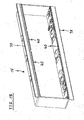
- FIG 1 illustrates a rear view of a decorative cover 10 for a front panel according to a first embodiment of the present invention.
- the front panel is provided for a domestic appliance.
- the decorative cover 10 is formed as a rectangular sheet and comprises four round holes 24.
- the round holes 24 are provided for receiving knobs or shafts of said knobs.
- the decorative cover 10 is made of glass.
- the decorative cover 10 may be made of plastics.
- a glue bead 18 is applied at an outer portion of the rear side of the decorative cover 10.
- the glue bead 18 has the form of a rectangular frame.
- An adhesive tape or a pierced adhesive foil may be used instead of said glue bead 18.
- the application of the glue bead 18 onto the decorative cover 10 is the first step of assembling the front panel of the first embodiment.
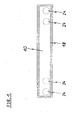
- FIG 2 illustrates a rear view of a support plate 12 with the decorative cover 10 for the front panel according to the first embodiment of the present invention.
- the support plate 12 is substantially formed as a rectangular sheet.
- a rectangular cutout is arranged in the central portion of the support plate 12. Said rectangular cutout is marginally smaller than the decorative cover 10 attached at the front side of the support plate 12.
- the rectangular cutout is enclosed by an embossing 22.
- the embossing 22 is provided for receiving the glue bead 18 of the decorative cover 10. The deepness of the embossing 22 defines the thickness of the glue bead 18 between the rear side of the decorative cover 10 and the front side of the support plate 12.
- the assembly of the support plate 12 and the decorative cover 10 is the second step of assembling the front panel of the first embodiment.
- FIG 3 illustrates a rear view of the support plate 12 with the decorative cover 10 for the front panel according to the first embodiment of the present invention.
- FIG 3 shows the same support plate 12 and the same decorative cover 10 as in FIG 2 .
- a further glue bead 20 is arranged on the rear side of the support plate 12.
- the glue bead 20 has the form of a rectangular frame and two transverse joints 26.
- the rectangular frame of the glue bead 20 has substantially the same size as the rectangular frame of the glue bead 18.
- an adhesive tape or a pierced adhesive foil may be used instead of the glue bead 20.
- the applying of the glue bead 20 onto the support plate 12 is the third step of assembling the front panel of the first embodiment.
- FIG 4 illustrates a rear view of the support plate 12 with the decorative cover 10 and a holding frame 16 for the front panel according to the first embodiment of the present invention.
- the holding frame 16 is attached in a central portion of the rear side of the support plate 12.
- the holding frame 16 is fixed by the glue bead 20.
- knob housings 14 are also attached at the rear side of the support plate 12. Two knob housings 14 are arranged side-by-side on the left and right sides of the holding frame 16 in each case. Each knob housing 14 corresponds with one of the round holes 24 of the decorative cover 10.
- the knob housings 14 are also fixed by the glue bead 20.
- the fixing of the holding frame 16 and the knob housings 14 at the support plate 12 is the fourth step of assembling the front panel of the first embodiment.
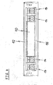
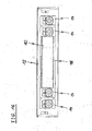
- FIG 5 illustrates a sectional side view of the support plate 12 with the decorative cover 10 and the holding frame 16 for the front panel according to the first embodiment of the present invention.
- FIG 5 clarifies the arrangement of the decorative cover 10, the support plate 12, the holding frame 16 and the glue beads 18 and 20.
- the decorative cover 10 is the foremost component of the front panel.
- the glue bead 18 between the decorative cover 10 and the support plate 12 is arranged in a space provided by the embossing 22.
- the decorative cover 10 lies directly against the support plate 12.
- the glue bead 20 between the support plate 12 and the holding frame 16 is arranged at rear side of the embossing 22 and opposite to the glue bead 18.
- FIG 6 illustrates a rear view of the decorative cover 10 for the front panel according to a second embodiment of the present invention. Same and similar components have the same reference numerals as in the first embodiment.
- the decorative cover 10 is formed as a rectangular sheet and comprises the four round holes 24.
- the round holes 24 are provided for receiving the knobs or the shafts of said knobs.
- the glue bead 18 is applied at an outer portion of the rear side of the decorative cover 10.
- the glue bead 18 has the form of a rectangular frame. Additionally, the glue bead 18 comprises six transverse joints 26, so that the round holes 24 are enclosed by the glue bead 18.
- an adhesive tape or a pierced adhesive foil may be used instead of said glue bead 18.
- the application of the glue bead 18 onto the decorative cover 10 is the first step of assembling the front panel of the second embodiment.
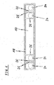
- FIG 7 illustrates a rear view of the support plate 12 with the decorative cover 10 for the front panel according to the second embodiment of the present invention.
- the support plate 12 of the second embodiment is similarly formed as the support plate 12 of the first embodiment.
- the embossing 22 comprises a plurality of holes 28. A part of the glue bead 18 expands through said holes 28, when the support plate 12 is put onto the decorative cover 10.
- the deepness of the embossing 22 defines the thickness of the glue bead 18 between the rear side of the decorative cover 10 and the front side of the support plate 12. That part of the glue bead 18 expanded through the holes 28 forms the glue bead 20 on the rear side of the support plate 12.
- the assembly of the support plate 12 and the decorative cover 10 is the second step of assembling the front panel of the second embodiment.
- FIG 8 illustrates a rear view of the support plate 12 with the decorative cover 10 and the holding frame 16 for the front panel according to the second embodiment of the present invention.
- the holding frame 16 and the four knob housings 14 are attached at the rear side of the support plate 12 in a similar way as in the first embodiment.
- the glue bead 20 between the support plate 12 on the one hand and the holding frame 16 and four knob housings 14 on the other hand is formed by the expansion of the glue bead 18 through the holes 28.
- the fixing of the holding frame 16 and the knob housings 14 at the support plate 12 is the third step of assembling the front panel of the second embodiment.
- FIG 9 illustrates a rear view of the decorative cover 10 for the front panel according to a third embodiment of the present invention.
- the glue bead 18 is applied at an outer portion of the rear side of the decorative cover 10 and has the form of a rectangular frame. Further, the glue bead 18 comprises the six transverse joints 26, so that the round holes 24 are enclosed by the glue bead 18 as in the second embodiment. Additionally, the glue bead 18 comprises a number of contractions 30 in its upper and lower parts. Said contractions 30 are provided in order to obtain places for glue dots.
- the application of the glue bead 18 onto the decorative cover 10 is the first step of assembling the front panel of the third embodiment.
- FIG 10 illustrates a rear view of the support plate 12 with the decorative cover 10 for the front panel according to the third embodiment of the present invention.
- the support plate 12 of the third embodiment has the same form as the support plate 12 of the second embodiment.
- a part of the glue bead 18 expands through the holes 28 in the embossing 22, except at the positions of the contractions 30 of the glue bead 18.
- the deepness of the embossing 22 defines the thickness of the glue bead 18 between the rear side of the decorative cover 10 and the front side of the support plate 12.
- the positions of the contractions 30 are provided for gluing dots of hot glue or UV glue.
- the assembly of the support plate 12 and the decorative cover 10 is the second step of assembling the front panel of the third embodiment.
- FIG 11 illustrates a rear view of the support plate 12 with the decorative cover 10 and the holding frame for the front panel according to the third embodiment of the present invention.
- the holding frame 16 and the four knob housings 14 are attached at the rear side of the support plate 12 in a similar way as in the second embodiment. Now the glue dots of hot glue or UV glue are set at the positions of the contractions 30. The holding frame 16 and the knob housings 14 are hold for a few seconds up to the glue of the gluing dots is hardened. In this way, a bending of the parts can be compensated. Thus, the assembly can be handled directly after the gluing process, since the holding frame 16 and the knob housings 14 are prefixed.
- the fixing of the holding frame 16 and the knob housings 14 at the support plate 12 is the third step of assembling the front panel of the third embodiment.
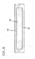
- FIG 12 illustrates a rear view of the decorative cover 10 and the support plate 12 for the front panel according to a fourth embodiment of the present invention.
- the support plate 12 is put onto the decorative cover 10. This is the first step of assembling the front panel of the fourth embodiment.
- FIG 13 illustrates a rear view of the decorative cover 10 and the support plate 12 with a glue bead 32 the front panel according to the fourth embodiment of the present invention.
- the glue bead 32 is applied onto the decorative cover 10.
- the glue bead 32 has the form of a rectangular frame.
- the glue bead 32 is inside the rectangular cutout of the support plate 12.
- an adhesive tape or a pierced adhesive foil may be used.
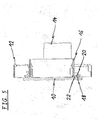
- FIG 14 illustrates a perspective front view of the knob housing 14 for the front panel according to the fourth embodiment of the present invention.
- Contact surfaces 34 and distance elements 36 are arranged at the front side of the knob housing 14.
- the contact surfaces 34 are arranged in lines at the upper and lower end portions of the front side, respectively.
- the distance elements 36 are arranged between the upper and lower lines of the contact surfaces 34.
- the contact surfaces 34 are provided to lie against the rear side of the support plate 12.
- the distance elements 36 are provided to lie against the rear side of the decorative cover 10.
- FIG 15 illustrates a perspective front view of the holding frame 16 for the front panel according to the fourth embodiment of the present invention.
- Contact surfaces 38 and distance elements 40 are arranged also at the front side of the holding frame 16.
- the longitudinal contact surfaces 38 form the upper and lower end portions of the front side, respectively.
- the distance elements 40 are arranged between the upper and lower contact surfaces 38.
- the contact surfaces 38 are provided to lie against the rear side of the support plate 12.
- the distance elements 40 are provided to lie against the rear side of the decorative cover 10.
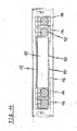
- FIG 16 illustrates a rear view of the support plate 12 with the decorative cover 10 and the holding frame 16 for the front panel according to the fourth embodiment of the present invention.
- the holding frame 16 is attached in a central portion of the rear side of the support plate 12.
- the holding frame 16 is fixed at the decorative cover 10 by the glue bead 32.
- the support plate 12 is clamped between the decorative cover 10 and the holding frame 16.
- the four knob housings 14 are also attached at the rear side of the support plate 12.
- the knob housings 14 are also fixed at the decorative cover 10 by the glue bead 32.
- the support plate 12 is clamped between the decorative cover 10 on the one hand and four knob housings 14 on the other hand.
- the fixing of the holding frame 16 and the knob housings 14 at the support plate 12 is the third step of assembling the front panel of the fourth embodiment.
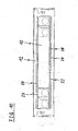
- FIG 17 illustrates a sectional side view of the support plate 12 with the decorative cover 10 and the knob housing 14 for the front panel according to the fourth embodiment of the present invention.
- FIG 17 clarifies the arrangement of the decorative cover 10, the support plate 12, the knob housing 14 and the glue bead 32.
- the decorative cover 10 is the foremost component of the front panel.
- the glue bead 32 between the decorative cover 10 and the knob housing 14 is arranged in a space provided by the distance elements 36.
- the support plate 12 is clamped between the decorative cover 10 on the one hand and four knob housings 14 on the other hand.
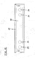
- FIG 18 illustrates a sectional side view of the support plate 12 with the decorative cover 10 and the holding frame 16 for the front panel according to the fourth embodiment of the present invention.
- FIG 18 clarifies the arrangement of the decorative cover 10, the support plate 12, the holding frame 16 and the glue bead 32.
- the decorative cover 10 is the foremost component of the front panel.
- the glue bead 32 between the decorative cover 10 and the holding frame 16 is arranged in a space provided by the distance elements 40.
- the support plate 12 is clamped between the decorative cover 10 and the holding frame 16.
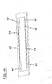
- FIG 19 illustrates a perspective front view of the support plate 12 for the front panel according to a fifth embodiment of the present invention.
- the support plate 12 includes a first embossing 42 at the upper and lower side of the cutout.
- the first embossing 42 is provided for receiving the holding frame 16 and the knob housings 14.
- the first embossing 42 comprises a number of centring elements 46.
- the support plate 12 includes a second embossing 44 enclosing the cutout.
- the second embossing 44 is provided for receiving the glue bead 18.
- FIG 20 illustrates a perspective front view of the support plate 12 with the holding frame 16 and the four knob housings 14 for the front panel according to the fifth embodiment of the present invention.
- the holding frame 16 and the four knob housings 14 are inserted in the cutout of the support plate 12.
- FIG 21 illustrates a perspective rear view of the support plate 12 with the holding frame 16 and the four knob housings 14 for the front panel according to the fifth embodiment of the present invention.
- the holding frame 16 and the knob housings 14 include hooks 48.
- the holding frame 16 and the knob housings 14 are inserted into the support plat 12, so that the contact surfaces 34 and 38 of the holding frame 16 and knob housings 14, respectively, contact the first embossing 42.
- the hooks 48 are provided for a pre-fixing the holding frame 16 and the knob housings 14.
- the glue bead 18 is applied onto the decorative cover 10.
- the support plate 12 with the holding frame 16 and the knob housings 14 is set downwards. The hooks 48 prevent that the holding frame 16 and the knob housings 14 get out of the support plate 12.
- the decorative cover 10 with the glue bead 18 can be set downwards onto the support plate 12 with the holding frame 16 and the knob housings 14, or the glue bead 18 is applied onto the support plate 12 with the holding frame 16 and the knob housings 14 and then the decorative cover 10 is set up.
- the hooks 48 are not necessary.
- FIG 22 illustrates a rear view of the decorative cover 10 for the front panel according to the fifth embodiment of the present invention.
- the decorative cover 10 is formed as a rectangular sheet and comprises the four round holes 24.
- the glue bead 18 is applied at the outer portion of the rear side of the decorative cover 10.
- the glue bead 18 has the form of a rectangular frame. Additionally, the glue bead 18 comprises six transverse joints 26, so that the round holes 24 are enclosed by the glue bead 18.
- an adhesive tape or a pierced adhesive foil may be used instead of said glue bead 18.
- FIG 23 illustrates a sectional side view of the support plate 12 with the decorative cover 10 and the holding frame 16 for the front panel according to the fifth embodiment of the present invention.
- FIG 23 clarifies the structure of the first embossing 42 and the second embossing 44.
- FIG 24 illustrates a perspective front view of the knob housing 14 for the front panel according to the fifth embodiment of the present invention.
- the knob housing 14 comprises the hooks 48 at its rear side. Said hooks 48 form a snap-in mechanism with the support plate 12.
- FIG 25 illustrates a perspective front view of the holding frame 16 for the front panel according to the fifth embodiment of the present invention.
- the holding frame 16 includes the contact surfaces 38 and the distance elements 40.
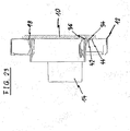
- FIG 26 illustrates a partial sectional side view of the support plate 12 with the decorative cover 10 and the holding frame 16 for the front panel according to the fifth embodiment of the present invention.
- FIG 26 clarifies the arrangement of the first embossing 42 and the second embossing 44.
- a part of the glue bead 18 is between the second embossing 44 and the decorative cover 10.
- Another part of the glue bead 18 is between the holding frame 16 and the decorative cover 10.
- the contact surface 34 of the holding frame 16 is supported by the first embossing 42.
- the method of the present invention reduces the number of steps for said method.
- Each embodiment of the inventive method can be performed manually or by a robot.
- the side walls of the decorative cover 10 can be illuminated for display and/or design purposes.
- a microsection at the side walls of the decorative cover 10 may be provided for coupling out of light.
- the possible structures of the microsections allow different effects.
- the coupling of light into the decorative cover 10 may be performed via holes for the knobs and/or keys or via additional holes.
- the decorative cover 10 may at least partially have a concave or convex structure in order to obtain the effects of lenses.
Landscapes
- Engineering & Computer Science (AREA)
- Textile Engineering (AREA)
- Chemical & Material Sciences (AREA)
- Combustion & Propulsion (AREA)
- Mechanical Engineering (AREA)
- General Engineering & Computer Science (AREA)
- Casings For Electric Apparatus (AREA)
Claims (15)
- Verfahren zur Montage einer Frontplatte für ein Haushaltsgerät, wobei das Verfahren die folgenden Schritte umfasst:- Bereitstellen einer dekorativen Abdeckung (10), die aus einem oder mehreren zumindest teilweise transparenten Werkstoffen hergestellt ist,- Bereitstellen einer Trägerplatte (12) mit einer rechteckigen Aussparung im mittleren Teil der Trägerplatte (12), die geringfügig kleiner als die dekorative Abdeckung (10) ist,- Bereitstellen mindestens einer Haltevorrichtung (14, 16) zum Aufnehmen von Steuerelementen und/oder Anzeigevorrichtungen,- Aufbringen einer Kleberaupe (18, 32) auf einer Rückseite der dekorativen Abdeckung (10),- Anbringen der Trägerplatte (12) auf der Rückseite der dekorativen Abdeckung (10) und- Anbringen der Haltevorrichtung (14, 16) auf der Kleberaupe (18, 32),- so dass die Kleberaupe (18, 32) zumindest teilweise durch die Trägerplatte (12) und/oder die Haltevorrichtung (14, 16) bedeckt ist.
- Verfahren nach Anspruch 1, wobei die bereitgestellte Trägerplatte (12) eine Prägung (22) umfasst, die zumindest teilweise die Aussparung der Trägerplatte (12) umschließt, oder wobei eine Prägung (22) entlang des Umfangs der Aussparung der Trägerplatte (12) hergestellt wird, wobei die Prägung (22) nach hinten gerichtet ist.
- Verfahren nach Anspruch 2, wobei die Dicke der Kleberaupe (18) zwischen der Rückseite der dekorativen Abdeckung (10) und der Vorderseite der Trägerplatte (12) durch die Tiefe der Prägung (22) definiert wird.
- Verfahren nach Anspruch 2 oder 3, wobei eine Vielzahl von Löchern (28) in der Prägung (22) hergestellt wird, so dass ein Teil der Kleberaupe (18) während der Befestigung der Trägerplatte (12) an der Rückseite der dekorativen Abdeckung (10) durch die Löcher (28) quillt.
- Verfahren nach einem der vorhergehenden Ansprüche, wobei die Kleberaupe (18) mit einer Anzahl von Verengungen (30) hergestellt wird, um eine Anzahl von Stellen für Klebepunkte zu erhalten, und wobei die Haltevorrichtung (14, 16) durch die Klebepunkte auf der Rückseite der Trägerplatte (12) vorbefestigt wird.
- Verfahren nach Anspruch 5, wobei die Trägerplatte (12) durch Kleben der Haltevorrichtung (14, 16) auf die dekorative Abdeckung (10) befestigt wird.
- Verfahren nach einem der vorhergehenden Ansprüche, wobei die Trägerplatte (12) und die Haltevorrichtung (14, 16) während der Befestigung der Trägerplatte (12) und der Haltevorrichtung (14, 16) zentriert und/oder ausgerichtet werden.
- Frontplatte für ein Haushaltsgerät, umfassend:- eine dekorative Abdeckung (10), die aus einem oder mehreren zumindest teilweise transparenten Werkstoffen hergestellt ist,- eine Trägerplatte (12) mit einer rechteckigen Aussparung im mittleren Teil der Trägerplatte (12), die geringfügig kleiner als die dekorative Abdeckung (10) ist,- mindestens eine Haltevorrichtung (14, 16) zum Aufnehmen von Steuerelementen und/oder Anzeigevorrichtungen,- eine Kleberaupe (18, 32), die auf einer Rückseite der dekorativen Abdeckung (10) aufgebracht ist, und wobei die Trägerplatte (12) an der Rückseite der dekorativen Abdeckung (10) angebracht ist und die Haltevorrichtung (14, 16) auf der Kleberaupe (18, 32) angebracht ist, so dass die Kleberaupe (18, 32) zumindest teilweise durch die Trägerplatte (12) und/oder der Haltevorrichtung (14, 16) bedeckt ist.
- Frontplatte nach Anspruch 8, wobei die Trägerplatte (12) eine Prägung (22) ümfasst, die zumindest teilweise die Aussparung der Trägerplatte (12) umschließt und wobei die Prägung (22) nach hinten gerichtet ist.
- Frontplatte nach Anspruch 9, wobei die Dicke der Kleberaupe (18) zwischen der Rückseite der dekorativen Abdeckung (10) und der Vorderseite der Trägerplatte (12) durch die Tiefe der Prägung (22) definiert wird.
- Frontplatte nach Anspruch 9 oder 10, wobei die Prägung (22) eine Vielzahl von Löchern (28) umfasst, so dass ein Teil der Kleberaupe (18) durch die Löcher (28) quillt.
- Frontplatte nach einem Ansprüche 8 bis 11, wobei die Kleberaupe (18) eine Anzahl von Verengungen (30) umfasst, so dass eine Anzahl von Stellen für Klebepunkte gebildet wird, und wobei die Haltevorrichtung (14, 16) durch die Klebepunkte auf der Rückseite der Trägerplatte (12) vorbefestigt wird.
- Frontplatte nach Anspruch 12, wobei die Trägerplatte (12) durch die Haltevorrichtung (14, 16) befestigt wird, die auf die dekorative Abdeckung (10) geklebt wird.
- Frontplatte nach einem der Ansprüche 8 bis 13, wobei die dekorative Abdeckung (10) die vorderste Komponente der Frontplatte ist.
- Frontplatte nach Anspruch 14, wobei die Seitenwände der dekorativen Abdeckung (10) für Anzeige- und/oder Design-Zwecke beleuchtet sind oder beleuchtet werden können.
Priority Applications (3)
| Application Number | Priority Date | Filing Date | Title |
|---|---|---|---|
| PL11185162T PL2581485T3 (pl) | 2011-10-14 | 2011-10-14 | Sposób montowania panelu przedniego do urządzenia gospodarstwa domowego oraz odpowiedni panel przedni |
| ES11185162.2T ES2496316T3 (es) | 2011-10-14 | 2011-10-14 | Método de montaje de un panel frontal para un aparato doméstico y panel frontal correspondiente |
| EP11185162.2A EP2581485B2 (de) | 2011-10-14 | 2011-10-14 | Verfahren zur Montage der Frontplatte eines Haushaltsgerätes und entsprechende Frontplatte |
Applications Claiming Priority (1)
| Application Number | Priority Date | Filing Date | Title |
|---|---|---|---|
| EP11185162.2A EP2581485B2 (de) | 2011-10-14 | 2011-10-14 | Verfahren zur Montage der Frontplatte eines Haushaltsgerätes und entsprechende Frontplatte |
Publications (3)
| Publication Number | Publication Date |
|---|---|
| EP2581485A1 EP2581485A1 (de) | 2013-04-17 |
| EP2581485B1 true EP2581485B1 (de) | 2014-06-11 |
| EP2581485B2 EP2581485B2 (de) | 2024-05-22 |
Family
ID=44862559
Family Applications (1)
| Application Number | Title | Priority Date | Filing Date |
|---|---|---|---|
| EP11185162.2A Active EP2581485B2 (de) | 2011-10-14 | 2011-10-14 | Verfahren zur Montage der Frontplatte eines Haushaltsgerätes und entsprechende Frontplatte |
Country Status (3)
| Country | Link |
|---|---|
| EP (1) | EP2581485B2 (de) |
| ES (1) | ES2496316T3 (de) |
| PL (1) | PL2581485T3 (de) |
Families Citing this family (7)
| Publication number | Priority date | Publication date | Assignee | Title |
|---|---|---|---|---|
| CN206070194U (zh) | 2015-11-02 | 2017-04-05 | Lg电子株式会社 | 衣物处理装置 |
| KR101708355B1 (ko) | 2015-11-02 | 2017-02-20 | 엘지전자 주식회사 | 의류처리장치 |
| KR101708354B1 (ko) | 2015-11-02 | 2017-02-20 | 엘지전자 주식회사 | 의류처리장치 |
| CN106032637B (zh) | 2015-11-02 | 2019-01-29 | Lg电子株式会社 | 衣物处理装置 |
| KR101708352B1 (ko) | 2015-11-02 | 2017-02-20 | 엘지전자 주식회사 | 의류처리장치 |
| CN106012440B (zh) | 2015-11-02 | 2018-09-14 | Lg电子株式会社 | 衣物处理装置 |
| CN108007064B (zh) * | 2016-10-27 | 2021-04-20 | 青岛海尔洗衣机有限公司 | 控制面板结构和家电设备 |
Family Cites Families (10)
| Publication number | Priority date | Publication date | Assignee | Title |
|---|---|---|---|---|
| IT8434067V0 (it) † | 1984-10-31 | 1984-10-31 | Zanussi Elettrodomestici | Porta per un forno di cottura. |
| TW455042U (en) † | 1995-07-19 | 2001-09-11 | Matsushita Electric Industrial Co Ltd | Operating apparatus and heating cooker using the same |
| US5584563A (en) * | 1996-01-16 | 1996-12-17 | General Electric Company | Appliance control assembly |
| DE29610047U1 (de) * | 1996-06-07 | 1996-08-22 | Schwarzbich, Jörg, 33615 Bielefeld | Bedienungskonsole für Haushaltsgeräte |
| EP1120606B1 (de) † | 2000-01-24 | 2006-03-29 | Sharp Kabushiki Kaisha | Kochgerät |
| DE20111406U1 (de) † | 2001-07-13 | 2001-10-11 | RATIONAL AG, 86899 Landsberg | Gargerätetüre mit Polyurethan-Klebung |
| DE102004046484B4 (de) * | 2004-09-23 | 2006-11-16 | Miele & Cie. Kg | Kastenförmige Bedienblende |
| DE102005024934B4 (de) * | 2005-05-31 | 2014-03-27 | BSH Bosch und Siemens Hausgeräte GmbH | Bedienblendenanordnung für ein Haushaltgerät |
| JP2007078296A (ja) † | 2005-09-16 | 2007-03-29 | Hitachi Appliances Inc | 加熱調理器 |
| PL1990698T3 (pl) * | 2007-05-10 | 2011-11-30 | Electrolux Home Products Corp Nv | Udoskonalony modułowy panel sterujący do urządzeń domowych |
-
2011
- 2011-10-14 EP EP11185162.2A patent/EP2581485B2/de active Active
- 2011-10-14 ES ES11185162.2T patent/ES2496316T3/es active Active
- 2011-10-14 PL PL11185162T patent/PL2581485T3/pl unknown
Also Published As
| Publication number | Publication date |
|---|---|
| PL2581485T3 (pl) | 2014-11-28 |
| ES2496316T3 (es) | 2014-09-18 |
| EP2581485A1 (de) | 2013-04-17 |
| EP2581485B2 (de) | 2024-05-22 |
Similar Documents
| Publication | Publication Date | Title |
|---|---|---|
| EP2581485B1 (de) | Verfahren zur Montage der Frontplatte eines Haushaltsgerätes und entsprechende Frontplatte | |
| JP6752857B2 (ja) | 自動車用レーダーセンサのためのカバー | |
| CN107757516B (zh) | 用于制造车辆内饰件的方法和车辆内饰件 | |
| US9015976B2 (en) | Frame assembly for display panel | |
| CN203687503U (zh) | 用于冰箱的门以及冰箱 | |
| US20190152129A1 (en) | Methods for Forming Electronic Devices with Bent Display Edges | |
| WO2019048452A1 (en) | METHOD FOR ASSEMBLING CURVED DISPLAY DEVICES | |
| EP3709780B1 (de) | Bedienfeld für eine vorrichtung, insbesondere für ein haushaltsgerät, und verfahren zur montage des besagten bedienfelds | |
| EP2390403B1 (de) | Verfahren zur Montage einer Blende eines Geräts, insbesondere eines Haushaltsgeräts | |
| US7096614B1 (en) | Military ribbon assembly | |
| EP2530554B1 (de) | Tragbare elektronische Vorrichtung | |
| US8405962B2 (en) | Electro-optical apparatus and display module | |
| KR102596527B1 (ko) | 디스플레이 패널용 케이스 및 이를 포함하는 디스플레이 장치 | |
| JP6594158B2 (ja) | 電子機器及びその製造方法 | |
| JP5941131B1 (ja) | 意匠シート付前面パネル及び意匠シート付前面パネルの製造方法 | |
| CN111107202B (zh) | 电子设备的安装方法及电子设备 | |
| KR101518198B1 (ko) | 다방향 벽시계 제조방법 및 다방향 벽시계 | |
| US20150348725A1 (en) | Sub-assembling method, sub-assembled unit, and apparatus with sub-assembled unit | |
| US7710508B2 (en) | Liquid crystal display including a bezel having sidewalls and sub-sidewalls | |
| JP2010084414A (ja) | 採光部付き扉 | |
| CN223962345U (zh) | 上膜和托盘贴合治具 | |
| CN205751964U (zh) | 一种电子设备及其侧键fpc装配总成 | |
| CN210639598U (zh) | 一种触控显示装置及显示装置 | |
| US12339534B2 (en) | Display apparatus and manufacturing method of the same | |
| JP2025095278A (ja) | 表示装置およびその製造方法 |
Legal Events
| Date | Code | Title | Description |
|---|---|---|---|
| PUAI | Public reference made under article 153(3) epc to a published international application that has entered the european phase |
Free format text: ORIGINAL CODE: 0009012 |
|
| 17P | Request for examination filed |
Effective date: 20120328 |
|
| AK | Designated contracting states |
Kind code of ref document: A1 Designated state(s): AL AT BE BG CH CY CZ DE DK EE ES FI FR GB GR HR HU IE IS IT LI LT LU LV MC MK MT NL NO PL PT RO RS SE SI SK SM TR |
|
| AX | Request for extension of the european patent |
Extension state: BA ME |
|
| GRAP | Despatch of communication of intention to grant a patent |
Free format text: ORIGINAL CODE: EPIDOSNIGR1 |
|
| RIC1 | Information provided on ipc code assigned before grant |
Ipc: A47L 15/42 20060101ALI20131129BHEP Ipc: D06F 39/00 20060101AFI20131129BHEP |
|
| INTG | Intention to grant announced |
Effective date: 20140108 |
|
| GRAS | Grant fee paid |
Free format text: ORIGINAL CODE: EPIDOSNIGR3 |
|
| GRAA | (expected) grant |
Free format text: ORIGINAL CODE: 0009210 |
|
| AK | Designated contracting states |
Kind code of ref document: B1 Designated state(s): AL AT BE BG CH CY CZ DE DK EE ES FI FR GB GR HR HU IE IS IT LI LT LU LV MC MK MT NL NO PL PT RO RS SE SI SK SM TR |
|
| REG | Reference to a national code |
Ref country code: GB Ref legal event code: FG4D |
|
| REG | Reference to a national code |
Ref country code: CH Ref legal event code: EP |
|
| REG | Reference to a national code |
Ref country code: IE Ref legal event code: FG4D |
|
| REG | Reference to a national code |
Ref country code: AT Ref legal event code: REF Ref document number: 672325 Country of ref document: AT Kind code of ref document: T Effective date: 20140715 |
|
| REG | Reference to a national code |
Ref country code: DE Ref legal event code: R096 Ref document number: 602011007558 Country of ref document: DE Effective date: 20140724 |
|
| REG | Reference to a national code |
Ref country code: NL Ref legal event code: T3 |
|
| REG | Reference to a national code |
Ref country code: ES Ref legal event code: FG2A Ref document number: 2496316 Country of ref document: ES Kind code of ref document: T3 Effective date: 20140918 |
|
| PG25 | Lapsed in a contracting state [announced via postgrant information from national office to epo] |
Ref country code: NO Free format text: LAPSE BECAUSE OF FAILURE TO SUBMIT A TRANSLATION OF THE DESCRIPTION OR TO PAY THE FEE WITHIN THE PRESCRIBED TIME-LIMIT Effective date: 20140911 Ref country code: GR Free format text: LAPSE BECAUSE OF FAILURE TO SUBMIT A TRANSLATION OF THE DESCRIPTION OR TO PAY THE FEE WITHIN THE PRESCRIBED TIME-LIMIT Effective date: 20140912 Ref country code: LT Free format text: LAPSE BECAUSE OF FAILURE TO SUBMIT A TRANSLATION OF THE DESCRIPTION OR TO PAY THE FEE WITHIN THE PRESCRIBED TIME-LIMIT Effective date: 20140611 Ref country code: FI Free format text: LAPSE BECAUSE OF FAILURE TO SUBMIT A TRANSLATION OF THE DESCRIPTION OR TO PAY THE FEE WITHIN THE PRESCRIBED TIME-LIMIT Effective date: 20140611 |
|
| REG | Reference to a national code |
Ref country code: AT Ref legal event code: MK05 Ref document number: 672325 Country of ref document: AT Kind code of ref document: T Effective date: 20140611 |
|
| REG | Reference to a national code |
Ref country code: LT Ref legal event code: MG4D |
|
| PG25 | Lapsed in a contracting state [announced via postgrant information from national office to epo] |
Ref country code: LV Free format text: LAPSE BECAUSE OF FAILURE TO SUBMIT A TRANSLATION OF THE DESCRIPTION OR TO PAY THE FEE WITHIN THE PRESCRIBED TIME-LIMIT Effective date: 20140611 Ref country code: SE Free format text: LAPSE BECAUSE OF FAILURE TO SUBMIT A TRANSLATION OF THE DESCRIPTION OR TO PAY THE FEE WITHIN THE PRESCRIBED TIME-LIMIT Effective date: 20140611 Ref country code: HR Free format text: LAPSE BECAUSE OF FAILURE TO SUBMIT A TRANSLATION OF THE DESCRIPTION OR TO PAY THE FEE WITHIN THE PRESCRIBED TIME-LIMIT Effective date: 20140611 Ref country code: RS Free format text: LAPSE BECAUSE OF FAILURE TO SUBMIT A TRANSLATION OF THE DESCRIPTION OR TO PAY THE FEE WITHIN THE PRESCRIBED TIME-LIMIT Effective date: 20140611 |
|
| REG | Reference to a national code |
Ref country code: PL Ref legal event code: T3 |
|
| PG25 | Lapsed in a contracting state [announced via postgrant information from national office to epo] |
Ref country code: PT Free format text: LAPSE BECAUSE OF FAILURE TO SUBMIT A TRANSLATION OF THE DESCRIPTION OR TO PAY THE FEE WITHIN THE PRESCRIBED TIME-LIMIT Effective date: 20141013 Ref country code: RO Free format text: LAPSE BECAUSE OF FAILURE TO SUBMIT A TRANSLATION OF THE DESCRIPTION OR TO PAY THE FEE WITHIN THE PRESCRIBED TIME-LIMIT Effective date: 20140611 Ref country code: EE Free format text: LAPSE BECAUSE OF FAILURE TO SUBMIT A TRANSLATION OF THE DESCRIPTION OR TO PAY THE FEE WITHIN THE PRESCRIBED TIME-LIMIT Effective date: 20140611 Ref country code: CZ Free format text: LAPSE BECAUSE OF FAILURE TO SUBMIT A TRANSLATION OF THE DESCRIPTION OR TO PAY THE FEE WITHIN THE PRESCRIBED TIME-LIMIT Effective date: 20140611 Ref country code: SK Free format text: LAPSE BECAUSE OF FAILURE TO SUBMIT A TRANSLATION OF THE DESCRIPTION OR TO PAY THE FEE WITHIN THE PRESCRIBED TIME-LIMIT Effective date: 20140611 |
|
| PG25 | Lapsed in a contracting state [announced via postgrant information from national office to epo] |
Ref country code: IS Free format text: LAPSE BECAUSE OF FAILURE TO SUBMIT A TRANSLATION OF THE DESCRIPTION OR TO PAY THE FEE WITHIN THE PRESCRIBED TIME-LIMIT Effective date: 20141011 Ref country code: AT Free format text: LAPSE BECAUSE OF FAILURE TO SUBMIT A TRANSLATION OF THE DESCRIPTION OR TO PAY THE FEE WITHIN THE PRESCRIBED TIME-LIMIT Effective date: 20140611 |
|
| REG | Reference to a national code |
Ref country code: DE Ref legal event code: R026 Ref document number: 602011007558 Country of ref document: DE |
|
| PLBI | Opposition filed |
Free format text: ORIGINAL CODE: 0009260 |
|
| 26 | Opposition filed |
Opponent name: WHIRLPOOL EUROPE SRL Effective date: 20150311 |
|
| PLAX | Notice of opposition and request to file observation + time limit sent |
Free format text: ORIGINAL CODE: EPIDOSNOBS2 |
|
| PG25 | Lapsed in a contracting state [announced via postgrant information from national office to epo] |
Ref country code: DK Free format text: LAPSE BECAUSE OF FAILURE TO SUBMIT A TRANSLATION OF THE DESCRIPTION OR TO PAY THE FEE WITHIN THE PRESCRIBED TIME-LIMIT Effective date: 20140611 |
|
| REG | Reference to a national code |
Ref country code: DE Ref legal event code: R026 Ref document number: 602011007558 Country of ref document: DE Effective date: 20150311 |
|
| PG25 | Lapsed in a contracting state [announced via postgrant information from national office to epo] |
Ref country code: MC Free format text: LAPSE BECAUSE OF FAILURE TO SUBMIT A TRANSLATION OF THE DESCRIPTION OR TO PAY THE FEE WITHIN THE PRESCRIBED TIME-LIMIT Effective date: 20140611 Ref country code: LU Free format text: LAPSE BECAUSE OF FAILURE TO SUBMIT A TRANSLATION OF THE DESCRIPTION OR TO PAY THE FEE WITHIN THE PRESCRIBED TIME-LIMIT Effective date: 20141014 |
|
| REG | Reference to a national code |
Ref country code: IE Ref legal event code: MM4A |
|
| PG25 | Lapsed in a contracting state [announced via postgrant information from national office to epo] |
Ref country code: SI Free format text: LAPSE BECAUSE OF FAILURE TO SUBMIT A TRANSLATION OF THE DESCRIPTION OR TO PAY THE FEE WITHIN THE PRESCRIBED TIME-LIMIT Effective date: 20140611 |
|
| PLBB | Reply of patent proprietor to notice(s) of opposition received |
Free format text: ORIGINAL CODE: EPIDOSNOBS3 |
|
| REG | Reference to a national code |
Ref country code: FR Ref legal event code: PLFP Year of fee payment: 5 |
|
| PG25 | Lapsed in a contracting state [announced via postgrant information from national office to epo] |
Ref country code: IE Free format text: LAPSE BECAUSE OF NON-PAYMENT OF DUE FEES Effective date: 20141014 |
|
| PG25 | Lapsed in a contracting state [announced via postgrant information from national office to epo] |
Ref country code: SM Free format text: LAPSE BECAUSE OF FAILURE TO SUBMIT A TRANSLATION OF THE DESCRIPTION OR TO PAY THE FEE WITHIN THE PRESCRIBED TIME-LIMIT Effective date: 20140611 |
|
| PG25 | Lapsed in a contracting state [announced via postgrant information from national office to epo] |
Ref country code: CY Free format text: LAPSE BECAUSE OF FAILURE TO SUBMIT A TRANSLATION OF THE DESCRIPTION OR TO PAY THE FEE WITHIN THE PRESCRIBED TIME-LIMIT Effective date: 20140611 Ref country code: BG Free format text: LAPSE BECAUSE OF FAILURE TO SUBMIT A TRANSLATION OF THE DESCRIPTION OR TO PAY THE FEE WITHIN THE PRESCRIBED TIME-LIMIT Effective date: 20140611 |
|
| PG25 | Lapsed in a contracting state [announced via postgrant information from national office to epo] |
Ref country code: HU Free format text: LAPSE BECAUSE OF FAILURE TO SUBMIT A TRANSLATION OF THE DESCRIPTION OR TO PAY THE FEE WITHIN THE PRESCRIBED TIME-LIMIT; INVALID AB INITIO Effective date: 20111014 Ref country code: MT Free format text: LAPSE BECAUSE OF FAILURE TO SUBMIT A TRANSLATION OF THE DESCRIPTION OR TO PAY THE FEE WITHIN THE PRESCRIBED TIME-LIMIT Effective date: 20140611 Ref country code: BE Free format text: LAPSE BECAUSE OF FAILURE TO SUBMIT A TRANSLATION OF THE DESCRIPTION OR TO PAY THE FEE WITHIN THE PRESCRIBED TIME-LIMIT Effective date: 20140611 |
|
| REG | Reference to a national code |
Ref country code: FR Ref legal event code: PLFP Year of fee payment: 6 |
|
| APBM | Appeal reference recorded |
Free format text: ORIGINAL CODE: EPIDOSNREFNO |
|
| APAH | Appeal reference modified |
Free format text: ORIGINAL CODE: EPIDOSCREFNO |
|
| REG | Reference to a national code |
Ref country code: FR Ref legal event code: PLFP Year of fee payment: 7 |
|
| PLAB | Opposition data, opponent's data or that of the opponent's representative modified |
Free format text: ORIGINAL CODE: 0009299OPPO |
|
| R26 | Opposition filed (corrected) |
Opponent name: WHIRLPOOL EUROPE SRL Effective date: 20150311 |
|
| PLAB | Opposition data, opponent's data or that of the opponent's representative modified |
Free format text: ORIGINAL CODE: 0009299OPPO |
|
| PG25 | Lapsed in a contracting state [announced via postgrant information from national office to epo] |
Ref country code: MK Free format text: LAPSE BECAUSE OF FAILURE TO SUBMIT A TRANSLATION OF THE DESCRIPTION OR TO PAY THE FEE WITHIN THE PRESCRIBED TIME-LIMIT Effective date: 20140611 |
|
| R26 | Opposition filed (corrected) |
Opponent name: WHIRLPOOL EUROPE SRL Effective date: 20150311 |
|
| REG | Reference to a national code |
Ref country code: FR Ref legal event code: PLFP Year of fee payment: 8 |
|
| PG25 | Lapsed in a contracting state [announced via postgrant information from national office to epo] |
Ref country code: AL Free format text: LAPSE BECAUSE OF FAILURE TO SUBMIT A TRANSLATION OF THE DESCRIPTION OR TO PAY THE FEE WITHIN THE PRESCRIBED TIME-LIMIT Effective date: 20140611 |
|
| PLAB | Opposition data, opponent's data or that of the opponent's representative modified |
Free format text: ORIGINAL CODE: 0009299OPPO |
|
| R26 | Opposition filed (corrected) |
Opponent name: WHIRLPOOL EMEA S.P.A. Effective date: 20150311 |
|
| PLAY | Examination report in opposition despatched + time limit |
Free format text: ORIGINAL CODE: EPIDOSNORE2 |
|
| PLAH | Information related to despatch of examination report in opposition + time limit modified |
Free format text: ORIGINAL CODE: EPIDOSCORE2 |
|
| PLBC | Reply to examination report in opposition received |
Free format text: ORIGINAL CODE: EPIDOSNORE3 |
|
| PLAB | Opposition data, opponent's data or that of the opponent's representative modified |
Free format text: ORIGINAL CODE: 0009299OPPO |
|
| PGFP | Annual fee paid to national office [announced via postgrant information from national office to epo] |
Ref country code: NL Payment date: 20221019 Year of fee payment: 12 |
|
| R26 | Opposition filed (corrected) |
Opponent name: WHIRLPOOL EMEA S.P.A. Effective date: 20150311 |
|
| PGFP | Annual fee paid to national office [announced via postgrant information from national office to epo] |
Ref country code: TR Payment date: 20221013 Year of fee payment: 12 Ref country code: ES Payment date: 20221222 Year of fee payment: 12 |
|
| PGFP | Annual fee paid to national office [announced via postgrant information from national office to epo] |
Ref country code: PL Payment date: 20221011 Year of fee payment: 12 |
|
| P01 | Opt-out of the competence of the unified patent court (upc) registered |
Effective date: 20230625 |
|
| APBM | Appeal reference recorded |
Free format text: ORIGINAL CODE: EPIDOSNREFNO |
|
| APBP | Date of receipt of notice of appeal recorded |
Free format text: ORIGINAL CODE: EPIDOSNNOA2O |
|
| APAH | Appeal reference modified |
Free format text: ORIGINAL CODE: EPIDOSCREFNO |
|
| APBU | Appeal procedure closed |
Free format text: ORIGINAL CODE: EPIDOSNNOA9O |
|
| PGFP | Annual fee paid to national office [announced via postgrant information from national office to epo] |
Ref country code: GB Payment date: 20231024 Year of fee payment: 13 |
|
| PUAH | Patent maintained in amended form |
Free format text: ORIGINAL CODE: 0009272 |
|
| STAA | Information on the status of an ep patent application or granted ep patent |
Free format text: STATUS: PATENT MAINTAINED AS AMENDED |
|
| 27A | Patent maintained in amended form |
Effective date: 20240522 |
|
| AK | Designated contracting states |
Kind code of ref document: B2 Designated state(s): AL AT BE BG CH CY CZ DE DK EE ES FI FR GB GR HR HU IE IS IT LI LT LU LV MC MK MT NL NO PL PT RO RS SE SI SK SM TR |
|
| REG | Reference to a national code |
Ref country code: DE Ref legal event code: R102 Ref document number: 602011007558 Country of ref document: DE |
|
| REG | Reference to a national code |
Ref country code: NL Ref legal event code: MM Effective date: 20231101 |
|
| PG25 | Lapsed in a contracting state [announced via postgrant information from national office to epo] |
Ref country code: NL Free format text: LAPSE BECAUSE OF NON-PAYMENT OF DUE FEES Effective date: 20231101 |
|
| PG25 | Lapsed in a contracting state [announced via postgrant information from national office to epo] |
Ref country code: NL Free format text: LAPSE BECAUSE OF NON-PAYMENT OF DUE FEES Effective date: 20231101 |
|
| PG25 | Lapsed in a contracting state [announced via postgrant information from national office to epo] |
Ref country code: ES Free format text: LAPSE BECAUSE OF FAILURE TO SUBMIT A TRANSLATION OF THE DESCRIPTION OR TO PAY THE FEE WITHIN THE PRESCRIBED TIME-LIMIT Effective date: 20240522 |
|
| PG25 | Lapsed in a contracting state [announced via postgrant information from national office to epo] |
Ref country code: ES Free format text: LAPSE BECAUSE OF FAILURE TO SUBMIT A TRANSLATION OF THE DESCRIPTION OR TO PAY THE FEE WITHIN THE PRESCRIBED TIME-LIMIT Effective date: 20240522 |
|
| GBPC | Gb: european patent ceased through non-payment of renewal fee |
Effective date: 20241014 |
|
| PG25 | Lapsed in a contracting state [announced via postgrant information from national office to epo] |
Ref country code: GB Free format text: LAPSE BECAUSE OF NON-PAYMENT OF DUE FEES Effective date: 20241014 |
|
| REG | Reference to a national code |
Ref country code: CH Ref legal event code: U11 Free format text: ST27 STATUS EVENT CODE: U-0-0-U10-U11 (AS PROVIDED BY THE NATIONAL OFFICE) Effective date: 20251101 |
|
| PGFP | Annual fee paid to national office [announced via postgrant information from national office to epo] |
Ref country code: DE Payment date: 20251028 Year of fee payment: 15 |
|
| PGFP | Annual fee paid to national office [announced via postgrant information from national office to epo] |
Ref country code: IT Payment date: 20251022 Year of fee payment: 15 |
|
| PGFP | Annual fee paid to national office [announced via postgrant information from national office to epo] |
Ref country code: FR Payment date: 20251027 Year of fee payment: 15 |
|
| PGFP | Annual fee paid to national office [announced via postgrant information from national office to epo] |
Ref country code: CH Payment date: 20251101 Year of fee payment: 15 |
|
| PG25 | Lapsed in a contracting state [announced via postgrant information from national office to epo] |
Ref country code: PL Free format text: LAPSE BECAUSE OF NON-PAYMENT OF DUE FEES Effective date: 20231014 |