EP2581293B1 - Dispositif de renforcement de liaison - Google Patents
Dispositif de renforcement de liaison Download PDFInfo
- Publication number
- EP2581293B1 EP2581293B1 EP12187211.3A EP12187211A EP2581293B1 EP 2581293 B1 EP2581293 B1 EP 2581293B1 EP 12187211 A EP12187211 A EP 12187211A EP 2581293 B1 EP2581293 B1 EP 2581293B1
- Authority
- EP
- European Patent Office
- Prior art keywords
- link
- links
- reinforcement device
- cell
- connection
- Prior art date
- Legal status (The legal status is an assumption and is not a legal conclusion. Google has not performed a legal analysis and makes no representation as to the accuracy of the status listed.)
- Active
Links
- 230000002787 reinforcement Effects 0.000 title claims 8
- 230000003014 reinforcing effect Effects 0.000 claims description 11
- 239000011324 bead Substances 0.000 claims description 4
- 239000004753 textile Substances 0.000 claims description 4
- 238000006073 displacement reaction Methods 0.000 claims description 3
- 238000005553 drilling Methods 0.000 claims description 3
- 238000009958 sewing Methods 0.000 claims description 2
- 238000005096 rolling process Methods 0.000 claims 1
- 230000035939 shock Effects 0.000 description 7
- 238000013016 damping Methods 0.000 description 4
- 229910000831 Steel Inorganic materials 0.000 description 2
- 239000010959 steel Substances 0.000 description 2
- 229920000271 Kevlar® Polymers 0.000 description 1
- 238000009825 accumulation Methods 0.000 description 1
- 230000002411 adverse Effects 0.000 description 1
- 239000004760 aramid Substances 0.000 description 1
- 229920006231 aramid fiber Polymers 0.000 description 1
- 229920001971 elastomer Polymers 0.000 description 1
- 239000000806 elastomer Substances 0.000 description 1
- 238000004880 explosion Methods 0.000 description 1
- 239000002360 explosive Substances 0.000 description 1
- 230000000977 initiatory effect Effects 0.000 description 1
- 238000003780 insertion Methods 0.000 description 1
- 230000037431 insertion Effects 0.000 description 1
- 239000004761 kevlar Substances 0.000 description 1
- 238000012423 maintenance Methods 0.000 description 1
- 239000000463 material Substances 0.000 description 1
- 239000000203 mixture Substances 0.000 description 1
- 230000000750 progressive effect Effects 0.000 description 1
- 238000000926 separation method Methods 0.000 description 1
- 238000003466 welding Methods 0.000 description 1
- 238000004804 winding Methods 0.000 description 1
Images


Classifications
-
- B—PERFORMING OPERATIONS; TRANSPORTING
- B62—LAND VEHICLES FOR TRAVELLING OTHERWISE THAN ON RAILS
- B62D—MOTOR VEHICLES; TRAILERS
- B62D24/00—Connections between vehicle body and vehicle frame
- B62D24/02—Vehicle body, not intended to move relatively to the vehicle frame, and mounted on vibration absorbing mountings, e.g. rubber pads
-
- F—MECHANICAL ENGINEERING; LIGHTING; HEATING; WEAPONS; BLASTING
- F41—WEAPONS
- F41H—ARMOUR; ARMOURED TURRETS; ARMOURED OR ARMED VEHICLES; MEANS OF ATTACK OR DEFENCE, e.g. CAMOUFLAGE, IN GENERAL
- F41H7/00—Armoured or armed vehicles
- F41H7/02—Land vehicles with enclosing armour, e.g. tanks
- F41H7/04—Armour construction
- F41H7/042—Floors or base plates for increased land mine protection
-
- F—MECHANICAL ENGINEERING; LIGHTING; HEATING; WEAPONS; BLASTING
- F41—WEAPONS
- F41H—ARMOUR; ARMOURED TURRETS; ARMOURED OR ARMED VEHICLES; MEANS OF ATTACK OR DEFENCE, e.g. CAMOUFLAGE, IN GENERAL
- F41H7/00—Armoured or armed vehicles
- F41H7/02—Land vehicles with enclosing armour, e.g. tanks
- F41H7/04—Armour construction
- F41H7/044—Hull or cab construction other than floors or base plates for increased land mine protection
Definitions
- the technical field of the invention is that of devices for reinforcing a connection between a cell and a carrier structure of a vehicle that can be subjected to a mine shock.
- the document FR 2 916 528 describes a device according to the preamble of claim 1.
- This device is designed to reduce the vibrations of a muffler compared to a vehicle body. It is suitable for movements of low amplitude (a few millimeters) and high frequency (of the order of the MHz).
- the invention proposes to solve the problem of the separation between the cell and the carrier structure of a vehicle when it is subjected to a mine shock without adversely affecting the driving comfort of the vehicle.
- the invention proposes means for reinforcing the flexible connection connecting the cell and the carrier structure without impairing the normal operation of this flexible structure.
- the subject of the invention is a device for reinforcing a connection between a carrier structure and a cell of a vehicle, a link having a maximum maximum deflection, a reinforcing device characterized in that it comprises at least one at least two links surrounding at least one element of the carrier structure with a clearance greater than the maximum deflection of the link, each link being made otherwise integral with the cell by at least one fixing means, each link being calibrated at break and being of different length so as to present a different game with the element of the structure.
- each link comprises a first and a second end, all the first ends of the links being integral with one and the same first fastening means and all the second ends of the links being integral with one and the same second means of fastening.
- fixation may comprise a corresponding housing with a bead obtained by winding and sewing an end of the links to obtain a recess connection.
- a fixing means may comprise a set of wedges and plates connected by a clamping means and ensuring the attachment of one end of the links by clamping.
- the links can be folded between the wedges and plates ensuring their pinching and will be guided by a drilling of a support secured to the cell and disposed between wedges and plates, a traction on a link causing a sliding of this link through the piercing and a progressive tearing of the link.
- at least one link may be formed by a textile strap.
- At least one link may be formed by a wire rope.
- a vehicle 100 comprises a cell 101 integral with a carrier structure 102 in the vicinity of longitudinal members 102a and 102b of the supporting structure 102.
- the links of the cell 101 with the carrier structure 102 is made by means of damping elements 50 of "silent block" type in the front part, and a pivot connection 51 in the rear part.
- the cell 101 in the vicinity of each of the longitudinal members 102a and 102b, is secured to binding reinforcing devices 1 against the shocks of mines.
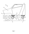
- the floor 101a of the vehicle cell (cell and vehicle visible to the figure 1 ) is integral with the spar 102a which is an element of the carrier structure of the vehicle.
- a binding reinforcing device 1 against mine shocks is secured to the floor 101a by a fastening means 2.
- This fastening means 2 comprises a plate 2c integral with the floor 101a of the vehicle by welding for example. Two pairs of support plates 2b integral with the plate 2c pass through the floor 101a.
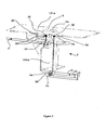
- the link reinforcing device 1 comprises at least two flexible links (three in number according to the described embodiment). Each of the links 3a, 3b, 3c is secured by each of its ends to the fastening means 2 at one of the pairs of support plates 2b. Each link 3a, 3b, 3c has a different length.
- the links 3a, 3b, 3c surround the spar 102a and are arranged in such a way that a link, the shortest 3a of the three, surrounds the spar 102a with a clearance J1 greater than the maximum clearance allowed by the link formed by the element. damper 50.
- This shortest link 3a is surrounded by a link of greater length 3b, which itself is surrounded by a longer link 3c.
- the longest link 3c surrounds the other two links 3a and 3b.
- the ends of the links 3a, 3b, 3c are wound on themselves and sewn together to form a bead 3d which is embedded with the fastening means 2.
- the embedding being done for example by insertion of the bead 3d in a corresponding housing 2d arranged between two support plates 2b.
- the lower part of the shortest link 3a is separated from the lower part of the spar 102a of the carrier structure 102 by a first functional clearance J1.
- This Game J1 is greater than the maximum travel C admissible by the vibration damping element 50.
- a second vertical clearance J2 separates the intermediate length link 3b from the lower part of the spar 102a.
- a third vertical clearance J3 separates the third link 3c, the longest link, from the lower part of the spar 102a. It is recalled that the spar 102a belongs to the supporting structure 102.
- the links are made in the form of textile straps comprising for example aramid fibers known under the name of Kevlar which is a registered trademark.
- Each of the links is calibrated at break in tension in order to obtain a break at a controlled energy level. Calibration at break can be done by choosing a section of the material of each means of connection adapted to the level of constraints from which one wishes to see breaking the link. The preferred location for breaking each link can be chosen by initiating a break in this place. In order to absorb progressively the energy of the mine shock, the tensile strength of each of the links can be chosen so as to increase progressively, from the shortest link to the longest link. The distance separating each link from the neighboring links may be different.
- the figure 3 shows another embodiment of the fastening means 2 (secured to the floor 101 of the vehicle cell).
- This means comprises a substantially vertical support plate 2b.
- This support plate 2b has a bore 2a in which are passed the three links 3a, 3b, 3c.
- the links are folded on both sides of the plate 2b.
- the links are pinched on both sides of the plate 2b by shims 2d and 2e.
- the clamping force exerted by the wedges 2d and 2e is provided by the tightening of two screws 2f which pass through the assembly formed by: the wedges 2d and 2e, the links 3a, 3b, 3c and the plate 2b. Tightening of the screws is done with a controlled torque.
- the traction exerted on the links 3a, 3b, 3c will cause them to slip between the wedges and tear gradually absorbing some of the impact energy.
- FIG. 4 the operation of the device according to the invention.
- a mine 104 bursts under the vehicle 100 producing a breath 105 which causes the lifting of the cell 101 of the vehicle 100.
- the brutally and massively released energy causes the breaking of the links 50 and 51 between the cell 101 and the carrier structure 102.
- the vertical displacement of the cell 101 with respect to the carrier structure 102 leads initially to the tensioning the shortest link 3a which breaks by absorbing part of the energy of the breath.
- the intermediate length link 3b in turn comes into contact with the carrier structure 102, it tends and breaks in turn also absorbing some of the remaining energy.
- the last link 3c (longest link) finally comes into contact with the carrier structure 102.
- the links may be made in the form of steel cables. A mix between steel cables and textile straps is also possible in order to better adapt the elongations and breaking strength capacities according to each link.
Landscapes
- Engineering & Computer Science (AREA)
- General Engineering & Computer Science (AREA)
- Chemical & Material Sciences (AREA)
- Combustion & Propulsion (AREA)
- Transportation (AREA)
- Mechanical Engineering (AREA)
- Body Structure For Vehicles (AREA)
- Aiming, Guidance, Guns With A Light Source, Armor, Camouflage, And Targets (AREA)
- Tents Or Canopies (AREA)
Description
- Le domaine technique de l'invention est celui des dispositifs de renforcement d'une liaison entre une cellule et une structure porteuse d'un véhicule pouvant être soumis à un choc de mine.
- Le document
FR 2 916 528 - Lorsqu'un véhicule comportant une cabine montée sur un châssis par l'intermédiaire de supports antivibratoires type "silent block" ou plus généralement, lorsqu'une cellule de véhicule montée sur une structure porteuse est soumise à un tir de mine par le dessous du véhicule, la cellule peut être amenée à se décrocher de la structure porteuse et à être projetée.
- Quand bien même la cellule serait protégée contre la perforation, sa projection constituerait un autre danger non négligeable pour les occupants.
- Pour limiter le débattement entre deux éléments mobiles relativement l'un par rapport à l'autre, il est connu dans le brevet
FR2867537 - Ce dispositif est conçu pour réduire les vibrations d'un pot d'échappement par rapport à une caisse de véhicule. Il est adapté à des mouvements de faible amplitude (quelques millimètres) et de fréquence élevée (de l'ordre du MHz).
- Il n'est en aucun cas adapté pour absorber l'énergie brutalement et massivement dissipée par l'explosion d'une mine ou autre engin explosif qui produit des déplacements rapides et de forte amplitude (de l'ordre de plusieurs dizaines de centimètres).
- Par ailleurs il est nécessaire pour assurer le confort de roulage de conserver une liaison entre châssis et cabine utilisant des supports antivibratoires souples.
- L'invention se propose de résoudre le problème de la désolidarisation entre la cellule et la structure porteuse d'un véhicule lorsqu'il est soumis à un choc de mine sans pour autant nuire au confort de roulage du véhicule.
Pour cela l'invention propose des moyens permettant de renforcer la liaison souple reliant la cellule et la structure porteuse sans pour autant nuire au fonctionnement normal de cette structure souple. - Ainsi pour résoudre ce problème, l'invention à pour objet un dispositif de renforcement d'une liaison entre une structure porteuse et une cellule d'un véhicule, liaison ayant un débattement maximal donné, dispositif de renforcement caractérisé en ce qu'il comporte au moins deux liens entourant au moins un élément de la structure porteuse avec un jeu supérieur au débattement maximal de la liaison, chaque lien étant rendu par ailleurs solidaire de la cellule par au moins un moyen de fixation, chaque lien étant calibré à la rupture et étant de longueur différente de façon à présenter un jeu différent avec l'élément de la structure.
Selon une caractéristique de l'invention, chaque lien comporte une première et une seconde extrémité, toutes les premières extrémités des liens étant solidaires d'un même premier moyen de fixation et toutes les secondes extrémités des liens étant solidaires d'un même second moyen de fixation.
Selon un premier mode de réalisation, un moyen de fixation pourra comporter un logement correspondant avec un bourrelet obtenu par enroulement et couture d'une extrémité des liens pour obtenir une liaison encastrement. - Selon un second mode de réalisation de l'invention, un moyen de fixation pourra comporter un jeu de cales et de plaques liées par un moyen de serrage et assurant la solidarisation d'une extrémité des liens par pincement.
Avantageusement, les liens pourront être pliés entre les cales et plaques assurant leur pincement et seront guidés par un perçage d'un support solidaire de la cellule et disposé entre cales et plaques, une traction sur un lien provoquant un glissement de ce lien au travers du perçage et un déchirement progressif du lien.
Selon différentes variantes, au moins un lien pourra être formé par une sangle textile.
Au moins un lien pourra être formé par un câble métallique. - L'invention sera mieux comprise à la lecture de la description suivante, description faite en référence aux dessins annexés dans lesquels:
- La
figure 1 représente une vue en coupe longitudinale de la partie avant d'un véhicule comportant un dispositif de renforcement selon l'invention. - La
figure 2 représente une vue de détail de trois quarts d'une partie d'un véhicule comportant un mode de réalisation d'un dispositif de renforcement selon l'invention. - La
figure 3 représente une vue de détail d'un autre mode de réalisation d'un moyen de fixation. - La
figure 4 représente une vue en coupe longitudinale de la partie avant d'un véhicule soumis à un choc de mine et comportant un dispositif de renforcement selon l'invention. - Selon la
figure 1 et selon un mode de réalisation, un véhicule 100 comporte une cellule 101 solidaire d'une structure porteuse 102 au voisinage de longerons 102a et 102b de la structure porteuse 102. Les liaisons de la cellule 101 avec la structure porteuse 102 est faite au moyen d'éléments amortisseurs 50 de type "silent block" dans la partie avant, et d'une liaison pivot 51 dans la partie arrière. La cellule 101, au voisinage de chacun des longerons 102a et 102b, est solidaire de dispositifs de renforcement de liaison 1 contre les chocs de mines.
Selon lafigure 2 , le plancher 101a de la cellule du véhicule (cellule et véhicule visibles à lafigure 1 ) est solidaire du longeron 102a qui est un élément de la structure porteuse du véhicule. La solidarisation est faite au moyen de l'élément amortisseur de vibrations 50, élément disposant d'une course verticale maximale C, les autres degrés de liberté étant inferieurs ou égaux à cette course.
Un dispositif de renforcement de liaison 1 contre les chocs de mines est rendu solidaire du plancher 101a par un moyen de fixation 2. Ce moyen de fixation 2 comporte une platine 2c solidaire du plancher 101a du véhicule par soudage par exemple. Deux paires de plaques support 2b solidaire de la platine 2c traversent le plancher 101a.
Le dispositif de renforcement de liaison 1 comporte au moins deux liens 3 souples (au nombre de trois selon le mode réalisation décrit). Chacun des liens 3a,3b,3c est solidaire par chacune de ses extrémités du moyen de fixation 2 au niveau d'une des paires de plaques support 2b. Chaque lien 3a,3b,3c a une longueur différente. Les liens 3a,3b,3c entourent le longeron 102a et sont disposés de telle manière qu'un lien, le plus court 3a des trois, entoure le longeron 102a avec un jeu J1 supérieur au débattement maximal admissible par la liaison formée par l'élément amortisseur 50. Ainsi le lien 3a ne gêne pas le fonctionnement normal du moyen amortisseur 50 lors du roulage du véhicule.
Ce lien le plus court 3a est entouré par un lien de longueur supérieur 3b, qui est lui-même entouré d'un lien plus long 3c. Le lien le plus long 3c entoure les deux autres liens 3a et 3b. Selon le mode de réalisation décrit, les extrémités des liens 3a,3b,3c sont enroulées sur elles-mêmes et cousues ensembles pour former un bourrelet 3d qui est encastré avec le moyen de fixation 2. L'encastrement se faisant par exemple par insertion du bourrelet 3d dans un logement correspondant 2d aménagé entre deux des plaques supports 2b.
On notera que la partie basse du lien le plus court 3a est séparée de la partie basse du longeron 102a de la structure porteuse 102 par un premier jeu fonctionnel J1. Ce Jeu J1 est supérieur à la course maximale C admissible par l'élément amortisseur de vibrations 50.
On notera que le fait que les liens sont souples et disposés à distance de la structure porteuse autorise des déplacements omnidirectionnels de la cellule par rapport à la structure porteuse.
Un second jeu vertical J2 sépare le lien de longueur intermédiaire 3b de la partie basse du longeron 102a. Un troisième jeu vertical J3 sépare le troisième lien 3c , lien le plus long, de la partie basse du longeron 102a. On rappelle que le longeron 102a appartient à la structure porteuse 102. - Selon le mode de réalisation décrit, les liens sont réalisés sous la forme de sangles textiles comportant par exemple des fibres aramides connues sous le nom de Kevlar qui est une marque déposé. Chacun des liens est calibré à la rupture en traction afin d'obtenir une rupture à un niveau d'énergie maîtrisé. Le calibrage à la rupture pourra se faire en choisissant une section du matériau de chaque moyen de liaison adaptée au niveau de contraintes à partir duquel on souhaite voir rompre le lien. L'endroit privilégié pour la rupture de chaque lien pourra être choisi en pratiquant une amorce de rupture à cet endroit. Afin d'absorber progressivement l'énergie du choc de mine, la résistance à la traction de chacun des liens pourra être choisie de manière à augmenter progressivement, du lien le plus court au lien le plus long.
La distance séparant chaque lien du ou des liens voisins pourra être différente. - La
figure 3 montre un autre mode de réalisation du moyen de fixation 2 (solidaire du plancher 101 de la cellule du véhicule). Ce moyen comporte une plaque support 2b sensiblement verticale. Cette plaque support 2b comporte un perçage 2a dans lequel sont passés les trois liens 3a,3b,3c. Les liens sont repliés de part et d'autre de la plaque 2b. Les liens sont pincés de part et d'autre de la plaque 2b par des cales 2d et 2e.
L'effort de pincement exercé par les cales 2d et 2e est fourni par le serrage de deux vis 2f qui traversent l'ensemble formé par : les cales 2d et 2e, les liens 3a,3b,3c et la plaque 2b. Le serrage des vis est effectué avec un couple maitrisé. Ainsi lors d'un choc de mines, la traction exercée sur les liens 3a,3b,3c amènera ceux ci à glisser entre les cales et à se déchirer progressivement en absorbant une partie de l'énergie du choc. - On a représenté à la
figure 4 le fonctionnement du dispositif selon l'invention.
Une mine 104 éclate sous le véhicule 100 en produisant un souffle 105 qui provoque le soulèvement de la cellule 101 du véhicule 100. L'énergie brutalement et massivement libérée provoque la rupture des liaisons 50 et 51 entre la cellule 101 et la structure porteuse 102.
Le déplacement vertical de la cellule 101 par rapport à la structure porteuse 102 conduit dans un premier temps à la mise en tension du lien le plus court 3a qui se rompt en absorbant une partie de l'énergie du souffle.
Dans un second temps, le lien de longueur intermédiaire 3b vient à son tour en contact avec la structure porteuse 102, il se tend et se rompt à son tour en absorbant lui aussi une partie de l'énergie restante.
Le dernier lien 3c (lien le plus long) vient enfin en contact avec la structure porteuse 102. Il est mis en tension et absorbe lui aussi de l'énergie par allongement et évite la projection de la cellule 101 au loin de la structure porteuse 102. Ce dernier lien est dimensionné pour ne pas se rompre assurant le maintien d'une solidarisation entre structure porteuse 102 et cabine 101.
La liaison entre la cellule 101 et la structure porteuse 102 est ainsi renforcée. Le distance totale D entre cellule 101 et structure porteuse 102 représente ainsi le cumul des jeux J1, J2, J3 et de l'allongement final du lien le plus long 3b, auxquels s'ajoute le cas échant la distance de glissement au niveau du moyen de fixation 2 si l'on emploie le mode de réalisation décrit à lafigure 3 .
Selon une variante, les liens pourront être réalisés sous la forme de câbles d'acier. Un panachage entre câbles d'acier et sangles textiles est également envisageable afin de mieux adapter les allongements et les capacités de résistance à la rupture en fonction de chaque lien.
Claims (7)
- Dispositif de renforcement (1) d'une liaison entre une structure porteuse (102) et une cellule (101) d'un véhicule (100), liaison ayant un débattement maximal donné, dispositif de renforcement caractérisé en ce qu'il comporte au moins deux liens (3a, 3b, 3c) entourant au moins un élément de la structure porteuse (102) avec un jeu (J1,J2,J3) supérieur au débattement maximal (C) de la liaison, chaque lien (3a, 3b,3c) étant rendu par ailleurs solidaire de la cellule (101) par au moins un moyen de fixation (2), chaque lien (3a, 3b, 3c) étant calibré à la rupture et étant de longueur différente de façon à présenter un jeu (J1,J2,J3) différent avec l'élément de la structure (102).
- Dispositif de renforcement (1) de liaison selon la revendication 1, caractérisé en ce que chaque lien (3a, 3b,3c) comporte une première et une seconde extrémité, toutes les premières extrémités des liens étant solidaires d'un même premier moyen de fixation (2) et toutes les secondes extrémités des liens étant solidaires d'un même second moyen de fixation (2).
- Dispositif de renforcement (1) de liaison selon la revendication 2, caractérisé en ce qu'au moins un moyen de fixation (2) comporte un logement (2d) correspondant avec un bourrelet (3d) obtenu par enroulement et couture d'une extrémité des liens (3a, 3b, 3c) pour obtenir une liaison encastrement.
- Dispositif de renforcement de liaison selon la revendication 2, caractérisé en ce qu'au moins un moyen de fixation (2) comporte un jeu de cales (2d, 2e) et de plaques liées (2b) par un moyen de serrage (2f) et assurant la solidarisation d'une extrémité des liens par pincement.
- Dispositif de renforcement de liaison selon la revendication 4, caractérisé en ce que les liens (3a, 3b 3c) sont pliés entre les cales (2d,2e) et plaques (2f) assurant leur pincement et sont guidés par un perçage (2a) d'un support (2c) solidaire de la cellule (101) et disposé entre cales (2d,2e) et plaques (2f), une traction sur un lien (3a) provoquant un glissement de ce lien (3a) au travers du perçage (2a) et un déchirement progressif du lien (3a).
- Dispositif de renforcement (1) de liaison selon une des revendications 1 à 5, caractérisé en ce qu'au moins un lien (3a, 3b, 3c) est formé par une sangle textile.
- Dispositif de renforcement (1) de liaison selon une des revendications 1 à 6, caractérisé en ce qu'au moins un lien (3a, 3b, 3c) est formé par un câble métallique.
Priority Applications (1)
| Application Number | Priority Date | Filing Date | Title |
|---|---|---|---|
| PL12187211T PL2581293T3 (pl) | 2011-10-14 | 2012-10-04 | Urządzenie wzmacniające połączenie |
Applications Claiming Priority (1)
| Application Number | Priority Date | Filing Date | Title |
|---|---|---|---|
| FR1103162A FR2981324B1 (fr) | 2011-10-14 | 2011-10-14 | Dispositif de renforcement de liaison |
Publications (2)
| Publication Number | Publication Date |
|---|---|
| EP2581293A1 EP2581293A1 (fr) | 2013-04-17 |
| EP2581293B1 true EP2581293B1 (fr) | 2014-05-14 |
Family
ID=46934486
Family Applications (1)
| Application Number | Title | Priority Date | Filing Date |
|---|---|---|---|
| EP12187211.3A Active EP2581293B1 (fr) | 2011-10-14 | 2012-10-04 | Dispositif de renforcement de liaison |
Country Status (6)
| Country | Link |
|---|---|
| EP (1) | EP2581293B1 (fr) |
| DK (1) | DK2581293T3 (fr) |
| ES (1) | ES2487270T3 (fr) |
| FR (1) | FR2981324B1 (fr) |
| PL (1) | PL2581293T3 (fr) |
| RS (1) | RS53345B (fr) |
Families Citing this family (1)
| Publication number | Priority date | Publication date | Assignee | Title |
|---|---|---|---|---|
| CN106672084A (zh) * | 2016-12-31 | 2017-05-17 | 北奔重型汽车集团有限公司 | 一种驾驶室底板转向轴孔防护装置 |
Family Cites Families (3)
| Publication number | Priority date | Publication date | Assignee | Title |
|---|---|---|---|---|
| JP4299050B2 (ja) * | 2003-04-30 | 2009-07-22 | キャタピラージャパン株式会社 | 運転室補強構造 |
| FR2867537B1 (fr) | 2004-03-12 | 2006-05-26 | Hutchinson | Dispositif de liaison antivibratoire |
| FR2916528B1 (fr) * | 2007-05-23 | 2009-07-17 | Nexter Systems Sa | Vehicule blinde leger modulaire et cabine mise en oeuvre dans un tel vehicule |
-
2011
- 2011-10-14 FR FR1103162A patent/FR2981324B1/fr not_active Expired - Fee Related
-
2012
- 2012-10-04 PL PL12187211T patent/PL2581293T3/pl unknown
- 2012-10-04 EP EP12187211.3A patent/EP2581293B1/fr active Active
- 2012-10-04 RS RS20140280A patent/RS53345B/en unknown
- 2012-10-04 DK DK12187211.3T patent/DK2581293T3/da active
- 2012-10-04 ES ES12187211.3T patent/ES2487270T3/es active Active
Also Published As
| Publication number | Publication date |
|---|---|
| PL2581293T3 (pl) | 2014-10-31 |
| DK2581293T3 (da) | 2014-08-11 |
| ES2487270T3 (es) | 2014-08-20 |
| FR2981324B1 (fr) | 2013-10-25 |
| EP2581293A1 (fr) | 2013-04-17 |
| FR2981324A1 (fr) | 2013-04-19 |
| RS53345B (en) | 2014-10-31 |
Similar Documents
| Publication | Publication Date | Title |
|---|---|---|
| ES2342460T3 (es) | Sistema adaptativo de tensor de correa para el control de polea de carga de par torsor reversible. | |
| FR2747633A1 (fr) | Vehicule ferroviaire a cabine de conduite comportant une structure absorbeuse d'energie a deformation progressive | |
| EP2189317A1 (fr) | Support de groupe motopropulseur à rupture programmée, fixé à un brancard d'un véhicule automobile | |
| FR2928877A1 (fr) | Structure de montage de groupe motopropulseur d'un vehicule electrique. | |
| CA2820670A1 (fr) | Structure primaire de fuselage pour aeronef comprenant des entretoises a rupture precoce pour accroitre l'absorption d'energie en cas de crash | |
| EP1849655A1 (fr) | Dispositif pour le transport de bicyclette | |
| EP2581293B1 (fr) | Dispositif de renforcement de liaison | |
| JP4763784B2 (ja) | 運転室用の衝突時拘束装置を備えたトラック | |
| FR2776244A1 (fr) | Dispositif de montage du moteur pour ameliorer la tenue au crash des vehicules | |
| EP0841204B1 (fr) | Véhicule automobile comportant un bloc motopropulseur doté d'une suspension à débattement limité | |
| WO2004052677A1 (fr) | Siege d'enfant pour automobile susceptible de basculer vers une position de protection | |
| EP1127778A1 (fr) | Véhicule comportant un système de protection en cas de choc | |
| US4089385A (en) | Device for binding an engine to a vehicle chassis or body | |
| EP1042139B1 (fr) | Dispositif d'antisoumarinage deployable d'une position inactive vers une position active | |
| FR2688177A1 (fr) | Siege de vehicule comportant un element de deformation en tant que protection pour le passager assis derriere en cas de collision. | |
| FR2964913A1 (fr) | Ensemble de protection d'un receptacle d'un systeme de stockage d'energie electrique pour un vehicule. | |
| EP0995641B2 (fr) | Dispositif de protection tel que filet de protection pour vehicule automobile | |
| EP1580096A1 (fr) | Châssis de véhicule comportant un dispositif antivibratoire | |
| EP2356008B1 (fr) | Dispositif de transport par cable muni de moyens d'amortissement | |
| EP1514739B1 (fr) | Dispositif de sécurite pour véhicule | |
| FR2726533A1 (fr) | Dispositif de lancement d'un aeronef | |
| CN102976219B (zh) | 缓冲装置、工程机械及其吊臂 | |
| FR2885575A1 (fr) | Dispositif d'arret de charges | |
| EP2822840B1 (fr) | Caisse de vehicule automobile a zone d'auvent rigidifiee par cable. | |
| FR2997381A1 (fr) | Nacelle decouplable pour vehicule |
Legal Events
| Date | Code | Title | Description |
|---|---|---|---|
| PUAI | Public reference made under article 153(3) epc to a published international application that has entered the european phase |
Free format text: ORIGINAL CODE: 0009012 |
|
| AK | Designated contracting states |
Kind code of ref document: A1 Designated state(s): AL AT BE BG CH CY CZ DE DK EE ES FI FR GB GR HR HU IE IS IT LI LT LU LV MC MK MT NL NO PL PT RO RS SE SI SK SM TR |
|
| AX | Request for extension of the european patent |
Extension state: BA ME |
|
| 17P | Request for examination filed |
Effective date: 20131017 |
|
| RBV | Designated contracting states (corrected) |
Designated state(s): AL AT BE BG CH CY CZ DE DK EE ES FI FR GB GR HR HU IE IS IT LI LT LU LV MC MK MT NL NO PL PT RO RS SE SI SK SM TR |
|
| GRAP | Despatch of communication of intention to grant a patent |
Free format text: ORIGINAL CODE: EPIDOSNIGR1 |
|
| INTG | Intention to grant announced |
Effective date: 20140127 |
|
| GRAS | Grant fee paid |
Free format text: ORIGINAL CODE: EPIDOSNIGR3 |
|
| GRAA | (expected) grant |
Free format text: ORIGINAL CODE: 0009210 |
|
| AK | Designated contracting states |
Kind code of ref document: B1 Designated state(s): AL AT BE BG CH CY CZ DE DK EE ES FI FR GB GR HR HU IE IS IT LI LT LU LV MC MK MT NL NO PL PT RO RS SE SI SK SM TR |
|
| REG | Reference to a national code |
Ref country code: GB Ref legal event code: FG4D Free format text: NOT ENGLISH |
|
| REG | Reference to a national code |
Ref country code: AT Ref legal event code: REF Ref document number: 668048 Country of ref document: AT Kind code of ref document: T Effective date: 20140615 |
|
| REG | Reference to a national code |
Ref country code: IE Ref legal event code: FG4D Free format text: LANGUAGE OF EP DOCUMENT: FRENCH |
|
| REG | Reference to a national code |
Ref country code: DE Ref legal event code: R096 Ref document number: 602012001764 Country of ref document: DE Effective date: 20140703 |
|
| REG | Reference to a national code |
Ref country code: DK Ref legal event code: T3 Effective date: 20140804 |
|
| REG | Reference to a national code |
Ref country code: ES Ref legal event code: FG2A Ref document number: 2487270 Country of ref document: ES Kind code of ref document: T3 Effective date: 20140820 |
|
| REG | Reference to a national code |
Ref country code: SE Ref legal event code: TRGR |
|
| REG | Reference to a national code |
Ref country code: NO Ref legal event code: T2 Effective date: 20140514 |
|
| REG | Reference to a national code |
Ref country code: NL Ref legal event code: VDEP Effective date: 20140514 |
|
| REG | Reference to a national code |
Ref country code: LT Ref legal event code: MG4D |
|
| PG25 | Lapsed in a contracting state [announced via postgrant information from national office to epo] |
Ref country code: IS Free format text: LAPSE BECAUSE OF FAILURE TO SUBMIT A TRANSLATION OF THE DESCRIPTION OR TO PAY THE FEE WITHIN THE PRESCRIBED TIME-LIMIT Effective date: 20140914 Ref country code: LT Free format text: LAPSE BECAUSE OF FAILURE TO SUBMIT A TRANSLATION OF THE DESCRIPTION OR TO PAY THE FEE WITHIN THE PRESCRIBED TIME-LIMIT Effective date: 20140514 Ref country code: GR Free format text: LAPSE BECAUSE OF FAILURE TO SUBMIT A TRANSLATION OF THE DESCRIPTION OR TO PAY THE FEE WITHIN THE PRESCRIBED TIME-LIMIT Effective date: 20140815 Ref country code: CY Free format text: LAPSE BECAUSE OF FAILURE TO SUBMIT A TRANSLATION OF THE DESCRIPTION OR TO PAY THE FEE WITHIN THE PRESCRIBED TIME-LIMIT Effective date: 20140514 |
|
| REG | Reference to a national code |
Ref country code: PL Ref legal event code: T3 |
|
| PG25 | Lapsed in a contracting state [announced via postgrant information from national office to epo] |
Ref country code: LV Free format text: LAPSE BECAUSE OF FAILURE TO SUBMIT A TRANSLATION OF THE DESCRIPTION OR TO PAY THE FEE WITHIN THE PRESCRIBED TIME-LIMIT Effective date: 20140514 Ref country code: HR Free format text: LAPSE BECAUSE OF FAILURE TO SUBMIT A TRANSLATION OF THE DESCRIPTION OR TO PAY THE FEE WITHIN THE PRESCRIBED TIME-LIMIT Effective date: 20140514 |
|
| REG | Reference to a national code |
Ref country code: EE Ref legal event code: FG4A Ref document number: E009707 Country of ref document: EE Effective date: 20140730 |
|
| PG25 | Lapsed in a contracting state [announced via postgrant information from national office to epo] |
Ref country code: PT Free format text: LAPSE BECAUSE OF FAILURE TO SUBMIT A TRANSLATION OF THE DESCRIPTION OR TO PAY THE FEE WITHIN THE PRESCRIBED TIME-LIMIT Effective date: 20140915 |
|
| PG25 | Lapsed in a contracting state [announced via postgrant information from national office to epo] |
Ref country code: RO Free format text: LAPSE BECAUSE OF FAILURE TO SUBMIT A TRANSLATION OF THE DESCRIPTION OR TO PAY THE FEE WITHIN THE PRESCRIBED TIME-LIMIT Effective date: 20140514 Ref country code: SK Free format text: LAPSE BECAUSE OF FAILURE TO SUBMIT A TRANSLATION OF THE DESCRIPTION OR TO PAY THE FEE WITHIN THE PRESCRIBED TIME-LIMIT Effective date: 20140514 |
|
| REG | Reference to a national code |
Ref country code: DE Ref legal event code: R097 Ref document number: 602012001764 Country of ref document: DE |
|
| PG25 | Lapsed in a contracting state [announced via postgrant information from national office to epo] |
Ref country code: NL Free format text: LAPSE BECAUSE OF FAILURE TO SUBMIT A TRANSLATION OF THE DESCRIPTION OR TO PAY THE FEE WITHIN THE PRESCRIBED TIME-LIMIT Effective date: 20140514 |
|
| PLBE | No opposition filed within time limit |
Free format text: ORIGINAL CODE: 0009261 |
|
| STAA | Information on the status of an ep patent application or granted ep patent |
Free format text: STATUS: NO OPPOSITION FILED WITHIN TIME LIMIT |
|
| 26N | No opposition filed |
Effective date: 20150217 |
|
| REG | Reference to a national code |
Ref country code: DE Ref legal event code: R097 Ref document number: 602012001764 Country of ref document: DE Effective date: 20150217 |
|
| PG25 | Lapsed in a contracting state [announced via postgrant information from national office to epo] |
Ref country code: MC Free format text: LAPSE BECAUSE OF FAILURE TO SUBMIT A TRANSLATION OF THE DESCRIPTION OR TO PAY THE FEE WITHIN THE PRESCRIBED TIME-LIMIT Effective date: 20140514 Ref country code: LU Free format text: LAPSE BECAUSE OF FAILURE TO SUBMIT A TRANSLATION OF THE DESCRIPTION OR TO PAY THE FEE WITHIN THE PRESCRIBED TIME-LIMIT Effective date: 20141004 |
|
| REG | Reference to a national code |
Ref country code: IE Ref legal event code: MM4A |
|
| PG25 | Lapsed in a contracting state [announced via postgrant information from national office to epo] |
Ref country code: SI Free format text: LAPSE BECAUSE OF FAILURE TO SUBMIT A TRANSLATION OF THE DESCRIPTION OR TO PAY THE FEE WITHIN THE PRESCRIBED TIME-LIMIT Effective date: 20140514 |
|
| REG | Reference to a national code |
Ref country code: FR Ref legal event code: PLFP Year of fee payment: 4 |
|
| PG25 | Lapsed in a contracting state [announced via postgrant information from national office to epo] |
Ref country code: IE Free format text: LAPSE BECAUSE OF NON-PAYMENT OF DUE FEES Effective date: 20141004 |
|
| PG25 | Lapsed in a contracting state [announced via postgrant information from national office to epo] |
Ref country code: BG Free format text: LAPSE BECAUSE OF FAILURE TO SUBMIT A TRANSLATION OF THE DESCRIPTION OR TO PAY THE FEE WITHIN THE PRESCRIBED TIME-LIMIT Effective date: 20140514 |
|
| PG25 | Lapsed in a contracting state [announced via postgrant information from national office to epo] |
Ref country code: MT Free format text: LAPSE BECAUSE OF FAILURE TO SUBMIT A TRANSLATION OF THE DESCRIPTION OR TO PAY THE FEE WITHIN THE PRESCRIBED TIME-LIMIT Effective date: 20140514 Ref country code: HU Free format text: LAPSE BECAUSE OF FAILURE TO SUBMIT A TRANSLATION OF THE DESCRIPTION OR TO PAY THE FEE WITHIN THE PRESCRIBED TIME-LIMIT; INVALID AB INITIO Effective date: 20121004 |
|
| REG | Reference to a national code |
Ref country code: FR Ref legal event code: PLFP Year of fee payment: 5 |
|
| PG25 | Lapsed in a contracting state [announced via postgrant information from national office to epo] |
Ref country code: SM Free format text: LAPSE BECAUSE OF FAILURE TO SUBMIT A TRANSLATION OF THE DESCRIPTION OR TO PAY THE FEE WITHIN THE PRESCRIBED TIME-LIMIT Effective date: 20140514 |
|
| REG | Reference to a national code |
Ref country code: FR Ref legal event code: PLFP Year of fee payment: 6 |
|
| PG25 | Lapsed in a contracting state [announced via postgrant information from national office to epo] |
Ref country code: MK Free format text: LAPSE BECAUSE OF FAILURE TO SUBMIT A TRANSLATION OF THE DESCRIPTION OR TO PAY THE FEE WITHIN THE PRESCRIBED TIME-LIMIT Effective date: 20140514 |
|
| REG | Reference to a national code |
Ref country code: FR Ref legal event code: PLFP Year of fee payment: 7 |
|
| PG25 | Lapsed in a contracting state [announced via postgrant information from national office to epo] |
Ref country code: AL Free format text: LAPSE BECAUSE OF FAILURE TO SUBMIT A TRANSLATION OF THE DESCRIPTION OR TO PAY THE FEE WITHIN THE PRESCRIBED TIME-LIMIT Effective date: 20140514 |
|
| PGFP | Annual fee paid to national office [announced via postgrant information from national office to epo] |
Ref country code: EE Payment date: 20210922 Year of fee payment: 10 |
|
| PGFP | Annual fee paid to national office [announced via postgrant information from national office to epo] |
Ref country code: RS Payment date: 20210928 Year of fee payment: 10 Ref country code: NO Payment date: 20210923 Year of fee payment: 10 |
|
| PGFP | Annual fee paid to national office [announced via postgrant information from national office to epo] |
Ref country code: AT Payment date: 20210923 Year of fee payment: 10 Ref country code: ES Payment date: 20211102 Year of fee payment: 10 |
|
| REG | Reference to a national code |
Ref country code: EE Ref legal event code: MM4A Ref document number: E009707 Country of ref document: EE Effective date: 20221031 |
|
| REG | Reference to a national code |
Ref country code: NO Ref legal event code: MMEP |
|
| REG | Reference to a national code |
Ref country code: AT Ref legal event code: MM01 Ref document number: 668048 Country of ref document: AT Kind code of ref document: T Effective date: 20221004 |
|
| PG25 | Lapsed in a contracting state [announced via postgrant information from national office to epo] |
Ref country code: RS Free format text: LAPSE BECAUSE OF NON-PAYMENT OF DUE FEES Effective date: 20221004 Ref country code: NO Free format text: LAPSE BECAUSE OF NON-PAYMENT OF DUE FEES Effective date: 20221031 Ref country code: EE Free format text: LAPSE BECAUSE OF NON-PAYMENT OF DUE FEES Effective date: 20221031 Ref country code: AT Free format text: LAPSE BECAUSE OF NON-PAYMENT OF DUE FEES Effective date: 20221004 |
|
| PGFP | Annual fee paid to national office [announced via postgrant information from national office to epo] |
Ref country code: TR Payment date: 20230925 Year of fee payment: 12 Ref country code: IT Payment date: 20230920 Year of fee payment: 12 Ref country code: GB Payment date: 20230920 Year of fee payment: 12 Ref country code: FI Payment date: 20230921 Year of fee payment: 12 Ref country code: CZ Payment date: 20230925 Year of fee payment: 12 |
|
| REG | Reference to a national code |
Ref country code: ES Ref legal event code: FD2A Effective date: 20231124 |
|
| PGFP | Annual fee paid to national office [announced via postgrant information from national office to epo] |
Ref country code: SE Payment date: 20230922 Year of fee payment: 12 Ref country code: PL Payment date: 20230925 Year of fee payment: 12 Ref country code: FR Payment date: 20230920 Year of fee payment: 12 Ref country code: DK Payment date: 20230920 Year of fee payment: 12 Ref country code: BE Payment date: 20230920 Year of fee payment: 12 |
|
| PG25 | Lapsed in a contracting state [announced via postgrant information from national office to epo] |
Ref country code: ES Free format text: LAPSE BECAUSE OF NON-PAYMENT OF DUE FEES Effective date: 20221005 |
|
| PG25 | Lapsed in a contracting state [announced via postgrant information from national office to epo] |
Ref country code: ES Free format text: LAPSE BECAUSE OF NON-PAYMENT OF DUE FEES Effective date: 20221005 |
|
| PGFP | Annual fee paid to national office [announced via postgrant information from national office to epo] |
Ref country code: DE Payment date: 20230920 Year of fee payment: 12 Ref country code: CH Payment date: 20231102 Year of fee payment: 12 |