EP2581292B1 - Load handling trolley - Google Patents
Load handling trolley Download PDFInfo
- Publication number
- EP2581292B1 EP2581292B1 EP12186194.2A EP12186194A EP2581292B1 EP 2581292 B1 EP2581292 B1 EP 2581292B1 EP 12186194 A EP12186194 A EP 12186194A EP 2581292 B1 EP2581292 B1 EP 2581292B1
- Authority
- EP
- European Patent Office
- Prior art keywords
- load
- ramp
- engager
- handling trolley
- load handling
- Prior art date
- Legal status (The legal status is an assumption and is not a legal conclusion. Google has not performed a legal analysis and makes no representation as to the accuracy of the status listed.)
- Active
Links
Images




Classifications
-
- B—PERFORMING OPERATIONS; TRANSPORTING
- B61—RAILWAYS
- B61D—BODY DETAILS OR KINDS OF RAILWAY VEHICLES
- B61D47/00—Loading or unloading devices combined with vehicles, e.g. loading platforms, doors convertible into loading and unloading ramps
-
- B—PERFORMING OPERATIONS; TRANSPORTING
- B62—LAND VEHICLES FOR TRAVELLING OTHERWISE THAN ON RAILS
- B62B—HAND-PROPELLED VEHICLES, e.g. HAND CARTS OR PERAMBULATORS; SLEDGES
- B62B3/00—Hand carts having more than one axis carrying transport wheels; Steering devices therefor; Equipment therefor
- B62B3/04—Hand carts having more than one axis carrying transport wheels; Steering devices therefor; Equipment therefor involving means for grappling or securing in place objects to be carried; Loading or unloading equipment
- B62B3/06—Hand carts having more than one axis carrying transport wheels; Steering devices therefor; Equipment therefor involving means for grappling or securing in place objects to be carried; Loading or unloading equipment for simply clearing the load from the ground
-
- B—PERFORMING OPERATIONS; TRANSPORTING
- B66—HOISTING; LIFTING; HAULING
- B66F—HOISTING, LIFTING, HAULING OR PUSHING, NOT OTHERWISE PROVIDED FOR, e.g. DEVICES WHICH APPLY A LIFTING OR PUSHING FORCE DIRECTLY TO THE SURFACE OF A LOAD
- B66F9/00—Devices for lifting or lowering bulky or heavy goods for loading or unloading purposes
- B66F9/06—Devices for lifting or lowering bulky or heavy goods for loading or unloading purposes movable, with their loads, on wheels or the like, e.g. fork-lift trucks
-
- B—PERFORMING OPERATIONS; TRANSPORTING
- B62—LAND VEHICLES FOR TRAVELLING OTHERWISE THAN ON RAILS
- B62B—HAND-PROPELLED VEHICLES, e.g. HAND CARTS OR PERAMBULATORS; SLEDGES
- B62B3/00—Hand carts having more than one axis carrying transport wheels; Steering devices therefor; Equipment therefor
- B62B3/008—Hand carts having more than one axis carrying transport wheels; Steering devices therefor; Equipment therefor having more than two axes
-
- B—PERFORMING OPERATIONS; TRANSPORTING
- B62—LAND VEHICLES FOR TRAVELLING OTHERWISE THAN ON RAILS
- B62B—HAND-PROPELLED VEHICLES, e.g. HAND CARTS OR PERAMBULATORS; SLEDGES
- B62B3/00—Hand carts having more than one axis carrying transport wheels; Steering devices therefor; Equipment therefor
- B62B3/009—Hand carts having more than one axis carrying transport wheels; Steering devices therefor; Equipment therefor of the single-track type
-
- B—PERFORMING OPERATIONS; TRANSPORTING
- B62—LAND VEHICLES FOR TRAVELLING OTHERWISE THAN ON RAILS
- B62B—HAND-PROPELLED VEHICLES, e.g. HAND CARTS OR PERAMBULATORS; SLEDGES
- B62B3/00—Hand carts having more than one axis carrying transport wheels; Steering devices therefor; Equipment therefor
- B62B3/04—Hand carts having more than one axis carrying transport wheels; Steering devices therefor; Equipment therefor involving means for grappling or securing in place objects to be carried; Loading or unloading equipment
- B62B3/06—Hand carts having more than one axis carrying transport wheels; Steering devices therefor; Equipment therefor involving means for grappling or securing in place objects to be carried; Loading or unloading equipment for simply clearing the load from the ground
- B62B3/0625—Hand carts having more than one axis carrying transport wheels; Steering devices therefor; Equipment therefor involving means for grappling or securing in place objects to be carried; Loading or unloading equipment for simply clearing the load from the ground using rigid mechanical lifting mechanisms, e.g. levers, cams or gears
-
- B—PERFORMING OPERATIONS; TRANSPORTING
- B62—LAND VEHICLES FOR TRAVELLING OTHERWISE THAN ON RAILS
- B62B—HAND-PROPELLED VEHICLES, e.g. HAND CARTS OR PERAMBULATORS; SLEDGES
- B62B3/00—Hand carts having more than one axis carrying transport wheels; Steering devices therefor; Equipment therefor
- B62B3/04—Hand carts having more than one axis carrying transport wheels; Steering devices therefor; Equipment therefor involving means for grappling or securing in place objects to be carried; Loading or unloading equipment
- B62B3/06—Hand carts having more than one axis carrying transport wheels; Steering devices therefor; Equipment therefor involving means for grappling or securing in place objects to be carried; Loading or unloading equipment for simply clearing the load from the ground
- B62B3/0643—Hand carts having more than one axis carrying transport wheels; Steering devices therefor; Equipment therefor involving means for grappling or securing in place objects to be carried; Loading or unloading equipment for simply clearing the load from the ground the wheels remaining stationary while the supporting surface is lifted
Landscapes
- Engineering & Computer Science (AREA)
- Transportation (AREA)
- Mechanical Engineering (AREA)
- Structural Engineering (AREA)
- Combustion & Propulsion (AREA)
- Civil Engineering (AREA)
- Chemical & Material Sciences (AREA)
- Life Sciences & Earth Sciences (AREA)
- Geology (AREA)
- Handcart (AREA)
- Loading Or Unloading Of Vehicles (AREA)
- Forklifts And Lifting Vehicles (AREA)
- Carriers, Traveling Bodies, And Overhead Traveling Cranes (AREA)
Description
- The present invention relates to load handling trolleys of the type that normally run in channel tracks. Such load handling trolleys comprise elongate load engagers which are raisable and lowerable relative to bogies (or other such wheeled trolleys), sometimes via ramp-and-roller means, as the load engager and the bogies are caused to move longitudinally relative to each other.
- A number of developments to load handling trolleys have been made over recent decades by the present applicant, from the inclusion of positive retention means between the load engager and a bogie assembly, as described in
EP0133042A1 , to alternative forms of such positive retention means as described inEP1251056A1 , to the current version of load handling trolley described and claimed inEP1897749A2 , and in use today -
JP2005-2393354A -
Figures 1 and2 illustrate a prior art load handling trolley of the type described inEP1897749A2 . Aload handling trolley 10 has a load engager 12 of inverted channel section, so that itsweb 14 will be upwards to engage a load (not shown) and itsside walls 16, 18 will depend downwardly. Betweenside walls 16, 18, and in closely adjacent clearance thereto, arebogie assemblies 20. Bogieassemblies 20 have spacedsides studs 26,rollers 28 andjournalled rods 30 forarticulation links 32 betweenbogie assemblies 20, of which there are at least two per load engager. -
Studs 26 also interconnect raising-and-lowering means 34 for raising and loweringbogie assemblies 20 situated betweenbogie side walls walls 36 having aroller 38 mounted therebetween. Associated withroller 38 is aramp 40 secured to the underside of load engager 12 byscrews 41, whereby, from a lowered position, movement of thebogie assemblies 20 along load engager 12 causesroller 38 to move overramp 40 to urge load engager 12 upwards relative tobogie assemblies 20. - Outside faces of
sides bogie assemblies 20 havegrooves 42 therein, along which pins 44 (shown in dotted outline), located on the inside faces ofside walls 16, 18 of load engage 12 travel as load engager 12 moves upwardly or downwardly relative tobogie assemblies 20.Grooves 42 have a first lower part 46 parallel to the lower edges ofsides bogie assemblies 20, an angled major portion 48 corresponding to the slope oframp 40 and an upper portion 50 parallel to the top edge ofsides bogie assemblies 20. Upper portion 50 occupies aprojection 52 extending above the major part of the top edge ofsides bogie assemblies 20. The end of lower part 46 ofgroove 42 is closed to limit the extent of travel ofpins 44, whilst the end of upper part 50 ofgroove 42 is open to allow fitting ofbogie assemblies 20 to load engager 12. - To provide maximum elevation of load engager 12 relative to
bogie assemblies 20 in prior artload handling trolley 10,projections 52 ofsides bogie assemblies 20 are accommodated in the lowered position inapertures 54 provided in the top of load engager 12, so as not to be proud thereof. Whenbogie assemblies 20 are moved longitudinally relative to load engager 12,grooves 42 inprojections 52 allow load engager 12 to be raised higher than would be possible with previously known bogie assembly sides. - As shown, the mechanism for moving bogie assemblies 20 longitudinally relative to load engager 12 is conventional. A
crank 56 is pivotally connected betweenside walls 16, 18 of load engager 12 to pivot about apin 58.Side walls 16, 18 of load engager 12 are connected by anend wall 60, and the top of load engager 12 at its end is open at 62 to receive an operating lever (not shown) that engages in ahole 66 in the top ofcrank 56. Pivotally connected tocrank 56 is a pair of laterally spaced links 68 (only one of which is shown). Pair ofcrank links 68 is pivotally connected to a respective one ofsides bogie assembly 20 by way of apivot pin connection 70. Eachcrank link 68 carries apivot pin 72, which acts as an abutment. - When it is required to elevate load engager 12 relative to a track (not shown) in which it is located, an operating lever (not shown) is inserted into
crank 56 and pivoted anticlockwise (according to the current viewpoint inFigures 1 and2 ) to movecrank 56 and thus displacebogie assembly 20 longitudinally by action oflinks 68. The displacement ofbogie assembly 20 causesramp 40 to be raised byroller 38 and hence load engager 12 is moved to a raised position for movement ofload handling trolley 10 along said track. The maximum displacement is such as to movepins 44 alonggrooves 42 to their upper portions 50. - Where
rollers 28 are in contact with said aforementioned track in normal operation ofload handling trolley 10, a clearance remains betweenpin 72 and the end surface ofsides bogie assembly 20. In the situation whereload handling trolley 10 projects beyond an end of said track, absence ofabutment pin 72 would result in considerable angular displacement betweenlink 68 andbogie assembly 20. However, by providingabutment pin 72, angular movement is constrained and, therefore, despite the fact that theend bogie 20 may be considered not to be sufficiently supported, longitudinal movement is generated to give the desired lift by movement ofroller 38 againstramp 40. - Although extremely successful, in the spirit of achieving continuous improvement in design and function, the present inventor has determined a manner of improving the design of such known load handling trolleys, which brings a number of benefits which will be described hereinafter.
- Accordingly, the present invention provides a load handling trolley, of the type that normally runs in a channel-led track, comprising: an elongate load engager, having a load-receiving surface, which is raisable and lowerable relative to at least one bogie assembly via raising-and-lowering means and a ramp which together cause the load engager and the bogie assembly to move longitudinally relative to each other, said raising-and-lowering means being comprised in the at least one bogie assembly and said ramp being provided on an underside of the load-receiving surface, wherein the ramp comprises guiding means, and the raising-and-lowering means comprises a pair of spaced walls, each being provided with a transverse protrusion which is arranged so as to movably cooperate with the guiding means of the ramp, thereby enabling raising and lowering of the load engager relative to the at least one bogie assembly.
- Provision of such a novel load handling trolley is advantageous for a number of reasons. Unlike prior art load handling trolleys in which the inside faces of the side walls of the load engager are provided with pins or studs which fit into grooves or slots provided in the side walls of the bogie assemblies fitted therein to enable raising and lowering of the load engager relative to the bogie assemblies by means of a ramp fitted to the underside of the load engager (substantially as show in prior art
Figures 1 and2 ), the present invention has simplified the design and construction of such load handling trolleys by providing the ramp fitted to the underside of the load engager with guiding means, and by providing the bogie assemblies with a raising-and-lowering means, which is movably cooperable with the guiding means of the ramp. - Such an arrangement has been found by the present inventor to be extremely beneficial because, although in the prior art engagers the pins provided in the depending side walls of the load engager were not designed to be intentionally load bearing, it was often the case, somewhat inevitably, that these elements did indeed become load bearing with the sometime result that the pins would shear off from the inside faces of the load engager. To repair the load handling trolley in such cases would be expensive as the entire load engager would need to be replaced in order for one pair of interior pins to be replaced, as the pins are cast as an integral part of the load engager. Furthermore, although the bogie assemblies were designed to be load bearing, providing grooves or slots in their side walls actually led to weak points in the side walls, and a further possible failure mode.
- The present invention overcomes these problems by providing the ramp on the underside of the load engager with guiding means and the at least one bogie assembly with a raising-and-lowering means including a pair of spaced walls each provided with a transverse protrusion; the inside faces of the load engager are no longer provided with pins or pegs, and the bogie assemblies are no longer provided with slots or grooves. As a result, if either of the ramp or the raising-and-lowering means should fail, either is easily, simply and cheaply replaceable.
- Preferably the ramp comprises a substantially wedge-shaped body having at least one inclined surface from which depend a pair of substantially triangular-shaped side surfaces, a flat surface opposite to the at least one inclined surface and an end surface; the ramp thus has a "thin end" and a "fat end". The guiding means is preferably provided as undercuts in the triangular-shaped side surfaces of the body below the at least one inclined surface forming contact surfaces. Preferably, the ramp resembles an inverted-T when viewed from its end surface (i.e. its fat end) with the flat surface facing upwardly.
- The ramp is preferably provided with at least two, contiguous inclined surfaces having a first and a second angle of inclination respectively, with the greatest angle of inclination being from where a first inclined surface meets the flat surface (i.e. from its thin end), and the lesser angle of inclination being from where the first inclined surface meets a second inclined surface (i.e. to its fat end). Provision of at least two such contiguous inclined surfaces is advantageous as it reduces the return force, from the first inclined surface having the greater angle of inclination to the second inclined surface having the lesser angle of inclination, that may otherwise act in the opposite direction to the force exerted by the mechanism (such as a ratchet mechanism or a hydraulic drive mechanism) that causes the load engager and the bogie assembly to move longitudinally relative to each other to raise the load engager. This force reduction is greatest towards the fat end of the ramp, i.e. towards the end of the second inclined surface distal from the first inclined surface.
- The end surface of the ramp may furthermore be provided with a tail portion. This tail portion may be formed as a further undercut, this time in the end surface of the body below the at least one inclined surface.
- The flat surface of the ramp is preferably provided with fixing means which enable the ramp to be affixed to the underside of the load-receiving surface of the load engager. Mutual fixing means may be provided in appropriate locations in the load engager. The ramp may usually be fixed substantially centrally with respect to the longitudinal axis of the load engager, such that the guiding means extend longitudinally.
- The transverse protrusions of the raising-and-lowering means are preferably each in the form of a pin, stud, peg or the like which extends inwardly towards the longitudinal axis of the load engager, so as to be movably cooperable with the guiding means of the ramp. Further preferably, the protrusions are provided in the form of a pair of opposed pins, studs or pegs, each of which extends inwardly towards the longitudinal axis of the load engager.
- The raising-and-lowering means preferably further comprises a roller associated with the ramp. When the load engager is in its lowered position, the (thin end) of the ramp may rest on, or nearly rest on, the roller, and when the load engager is caused to be raised, the at least one inclined surface of the ramp is caused to contact (if not already in contact) and travel over the roller towards its end surface (the fat end) to an end point, which defines the extent of travel.
- The spaced side walls may each have a projection above a top edge of a major portion of its length, in which projection the associated transverse protrusion may preferably be located. The projection is preferably accommodated in an aperture provided in the load-receiving surface of the load engager when the load engager is in a lowered position.
- Consequentially, the at least one transverse protrusion is locatable adjacent to, but above, the guiding means of the ramp, which is wholly located within the at least one bogie assembly, when the load engager is in its lowered position, in which the load handling trolley is movable. When the load engager is in its raised position, the at least one transverse protrusion has been caused to move along the length of the guiding means, such that the ramp is wholly located above the at least one bogie assembly, with the result that the maximum possible lift of the load engager relative to the at least one bogie assembly has been achieved.
- The present invention will now be more particularly described, by way of non-limiting example only, with reference to the accompanying schematic drawings (not to scale), in which:
-
Figure 1 shows a prior art load handling trolley as hereinbefore described; -
Figure 2 is an exploded view of the prior art load handling trolley ofFigure 1 ; -
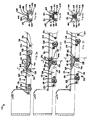
Figures 3a, 3b and 3c show, in longitudinal cross-section, a load handling trolley in accordance with the invention between its lowered and raised positions respectively; -
Figures 4a, 4b and 4c show transverse cross sections of the load handling trolley shown inFigures 3a, 3b and 3c taken along lines A-A, B-B and C-C ofFigures 3a, 3b and 3c respectively; -
Figure 5 is a first perspective view of a ramp usable in a load handling trolley of the invention; -
Figure 6 is a second perspective view of the ramp ofFigure 5 ; -
Figure 7 is a third perspective view of the ramp ofFigures 5 and 6 ; -
Figure 8 is partial view of a portion of the load engager shown inFigures 3a, 3b, 3c, 4a, 4b and 4c ; and -
Figure 9 is partial view of a portion of the load handling trolley shown inFigures 3a, 3b, 3c, 4a, 4b and 4c . - Referring to the
Figures 3a, 3b, 3c, 4a, 4b and 4c , aload handling trolley 110 has aload engager 112 of inverted channel section, so that itsweb 114, in the form of a load-receiving surface, will be upwards to engage a load (not shown) and its (optional)side walls side walls bogie assemblies 120.Bogie assemblies 120 have spacedsides studs 126,rollers 128 andjournalled rods 130 for articulation links (not shown) betweenbogie assemblies 120, of which there are at least two per load engager. -
Studs 126 also interconnect raising-and-lowering means 134 for raising and loweringbogie assemblies 120 situated betweenbogie side walls walls 136, each being provided with apin 144 which extends transversely and inwardly towards the longitudinal axis ofload engager 112, having aroller 138 mounted therebetween. Associated withroller 138 is aramp 140 secured to the underside of theload engager 112 byscrews 141, whereby, from a lowered position, movement of thebogie assemblies 120 in a longitudinal direction along theload engager 112 causes theroller 138 to move over theramp 140 to urge theload engager 112 upwards relative to thebogie assemblies 120. - As shown in
Figures 5, 6 and 7 ,ramp 140 comprises a substantially wedge-shapedbody 500 having a firstinclined surface 501 and a secondinclined surface 502, from the both of which depend a pair of substantially triangular-shaped side surfaces 503, 504, aflat surface 505 opposite to the first and secondinclined surfaces end surface 506; ramp 140 thus has a "thin end" and a "fat end". -
Ramp 140 is provided with a guiding means, in the form of a pair ofundercuts 507 in triangular-shaped side surfaces 503, 504 ofbody 500 below first and secondinclined surfaces ramp 140 resembles an inverted-T when viewed from its end surface 506 (i.e. its fat end) withflat surface 505 facing upwardly. -
End surface 506 oframp 140 is furthermore provided with atail portion 509, which is formed as a further undercut 510 inend surface 506 ofbody 500 below the secondinclined surface 502. -
Flat surface 505 oframp 140 is provided with fixing means, in the form of screw holes 511, 512, which enableramp 140 to be affixed to the underside of load-receivingsurface 114 ofload engager 112, via screws 141. Mutual fixing means may be provided in appropriate locations in the load engager.Ramp 140 is fixed substantially centrally with respect to the longitudinal axis ofload engager 112, such that the guiding means extend longitudinally, as shown inFigures 3a, 3b, 3c, 4a, 4b and 4c , and also inFigure 8 . - In order to provide maximum elevation of
load engager 112 relative tobogie assemblies 120,projections 152 of raising-and-lowering means 134 are accommodated, in the lowered position, inapertures 154 in the load-receivingsurface 154 ofload engager 112, so as not to be proud thereof, as shown inFigures 3a, 4a and9 . Whenbogie assemblies 120 are moved longitudinally relative to loadengager 112, as shown inFigures 3b and 4b , to a maximum lift height, as shown inFigures 3c and 4c ,load engager 112 is caused to be raised at least as high as is achievable with the prior art load handling trolley described and illustrated inFigures 1 and2 herein. - Longitudinal displacement of
bogie assemblies 120 causesramp 140 to be raised byroller 138 and henceload engager 112 is moved to a raised position as shown inFigures 3c and 4c of the drawings for movement ofload handling trolley 110 along a track (not shown). The maximum displacement is such as to movepins 144 along contact surfaces 508 oframps 140 to their end points of travel. Lowering ofload engager 112 is achieved by causingbogie assemblies 120 to be displaced in the opposite direction, thereby causingpins 144 to move in the opposite direction along contact surfaces 508 oframps 140 untilpins 144 are once again located inapertures 154 in load-receivingsurface 114. - The mechanism for moving the
bogie assemblies 120 longitudinally relative to the load engager may be conventional, such as that described inEP1897749A2 , or any other ratchet-type drive mechanism or hydraulic drive mechanism.
Claims (14)
- A load handling trolley (110), of the type that normally runs in a channel-led track, comprising:an elongate load engager (112), having a load-receiving surface (114), which is raisable and lowerable relative to at least one bogie assembly (120) via raising-and-lowering means (134) and a ramp (140) which together cause the load engager (112) and the bogie assembly (120) to move longitudinally relative to each other, said raising-and-lowering means (134) being comprised in the at least one bogie assembly (120) and said ramp (140) being provided on an underside of the load-receiving surface (114),wherein the ramp (140) comprises guiding means (508), and the raising-and-lowering means (134) comprises a pair of spaced walls (136), each being provided with a transverse protrusion (144) which is arranged so as to movably cooperate with the guiding means (508) of the ramp (140), thereby enabling raising and lowering of the load engager (112) relative to the at least one bogie assembly (120).
- A load handling trolley (110) as claimed in claim 1 wherein the ramp (140) comprises a substantially wedge-shaped body (500) having at least one inclined surface (501, 502) from which depend a pair of substantially triangular-shaped side surfaces (503, 504), a flat surface (505) opposite to the at least one inclined surface (501, 502) and an end surface (506).
- A load handling trolley (110) as claimed in claim 2 wherein the guiding means (508) is provided as undercuts (507) in the triangular-shaped side surfaces (503, 504) of the body (500) below the at least one inclined surface (501, 502) forming contact surfaces (508).
- A load handling trolley (110) as claimed in claim 2 or 3 wherein the ramp (140) is provided with at least two, contiguous inclined surfaces (501, 502) having a first (Θ1) and a second (Θ2) angle of inclination respectively.
- A load handling trolley (110) as claimed in any of claims 2 to 4 wherein the end surface (506) of the ramp (140) is provided with a tail portion (509).
- A load handling trolley (110) as claimed in claim 5 wherein the tail portion (509) is formed as a further undercut (510) in the end surface (506) of the body (500) below the at least one inclined surface (501, 502).
- A load handling trolley (110) as claimed in any of claims 2 to 6 wherein the flat surface (505) of the ramp (140) is provided with fixing means (511, 512) which enable the ramp (140) to be affixed to the underside of the load-receiving surface (114) of the load engager (112).
- A load handling trolley (110) as claimed in claim 7 wherein mutual fixing means (141) are provided in appropriate locations in the load engager (112).
- A load handling trolley (110) as claimed in any preceding claim wherein the ramp (140) is fixed substantially centrally with respect to a longitudinal axis of the load engager (112), such that the guiding means (508) extend longitudinally.
- A load handling trolley (110) as claimed in any preceding claim wherein the transverse protrusions (144) of the raising-and-lowering means (134) are each in the form of a pin, stud, peg or the like which extends inwardly towards a longitudinal axis of the load engager (112), so as to be movably cooperable with the guiding means (508) of the ramp (140).
- A load handling trolley (110) as claimed in claim 10 wherein the protrusions (144) are provided in the form of a pair of opposed pins, studs or pegs, each of which extends inwardly towards the longitudinal axis of the load engager (112).
- A load handling trolley (110) as claimed in any preceding claim wherein the raising-and-lowering means (134) comprises a roller (138) associated with the ramp (140).
- A load handling trolley (110) as claimed in any preceding claim wherein the spaced walls (136) each have a projection (152) above a top edge of a major
portion of its length, in which projection (152) the associated transverse protrusion (144) is located. - A load handling trolley (110) as claimed in claim 13 wherein the projection (152) is accommodated in an aperture (154) provided in the load-receiving surface (114) of the load engager (112) when the load engager (112) is in a lowered position.
Applications Claiming Priority (1)
| Application Number | Priority Date | Filing Date | Title |
|---|---|---|---|
| GBGB1117549.4A GB201117549D0 (en) | 2011-10-11 | 2011-10-11 | Load handling trolley |
Publications (2)
| Publication Number | Publication Date |
|---|---|
| EP2581292A1 EP2581292A1 (en) | 2013-04-17 |
| EP2581292B1 true EP2581292B1 (en) | 2014-06-25 |
Family
ID=45091870
Family Applications (1)
| Application Number | Title | Priority Date | Filing Date |
|---|---|---|---|
| EP12186194.2A Active EP2581292B1 (en) | 2011-10-11 | 2012-09-26 | Load handling trolley |
Country Status (4)
| Country | Link |
|---|---|
| EP (1) | EP2581292B1 (en) |
| JP (1) | JP6086693B2 (en) |
| KR (1) | KR101905017B1 (en) |
| GB (1) | GB201117549D0 (en) |
Families Citing this family (3)
| Publication number | Priority date | Publication date | Assignee | Title |
|---|---|---|---|---|
| JP6336366B2 (en) * | 2014-09-25 | 2018-06-06 | オールセーフ株式会社 | Cargo truck |
| WO2018081741A1 (en) * | 2016-10-31 | 2018-05-03 | Innovative Logistics, Inc. | Skate system and movable platform |
| US12703413B2 (en) | 2024-06-11 | 2026-08-11 | Dimension Product Solutions LP | Automated loading and unloading apparatus |
Family Cites Families (4)
| Publication number | Priority date | Publication date | Assignee | Title |
|---|---|---|---|---|
| MX159453A (en) | 1983-07-30 | 1989-06-09 | Joloda Loading Systems Ltd | A TROLLEY TO HANDLE LOAD |
| GB0109702D0 (en) | 2001-04-20 | 2001-06-13 | Blackrock Engineering Ltd | Load handling trolley |
| JP2005239335A (en) * | 2004-02-25 | 2005-09-08 | Junji Sato | Conveying trolley |
| GB0617661D0 (en) | 2006-09-08 | 2006-10-18 | Blackrock Engineering Ltd | Load handling trolley |
-
2011
- 2011-10-11 GB GBGB1117549.4A patent/GB201117549D0/en not_active Ceased
-
2012
- 2012-09-26 EP EP12186194.2A patent/EP2581292B1/en active Active
- 2012-10-10 KR KR1020120112493A patent/KR101905017B1/en active Active
- 2012-10-10 JP JP2012224979A patent/JP6086693B2/en active Active
Also Published As
| Publication number | Publication date |
|---|---|
| KR20130039310A (en) | 2013-04-19 |
| JP2013082444A (en) | 2013-05-09 |
| GB201117549D0 (en) | 2011-11-23 |
| EP2581292A1 (en) | 2013-04-17 |
| KR101905017B1 (en) | 2018-10-05 |
| JP6086693B2 (en) | 2017-03-01 |
Similar Documents
| Publication | Publication Date | Title |
|---|---|---|
| EP3145852B1 (en) | Vehicle lift | |
| JP5990395B2 (en) | Step device and railway vehicle provided with the step device | |
| JP5057039B2 (en) | Carriage transfer equipment | |
| EP2581292A1 (en) | Load handling trolley | |
| EP1897749B1 (en) | Load handling trolley | |
| EP0684175A1 (en) | Load handling trolley | |
| KR20250009998A (en) | Barrier-free sliding door with carriage for laterally adjustable door leaf | |
| CN100526138C (en) | Carrying apparatus with lifting carried object support table | |
| CN110371507B (en) | A locking device for container | |
| KR101510681B1 (en) | Scissors-type lift | |
| EP1249364B1 (en) | Improvements in and relating to load handling skates | |
| JP6336366B2 (en) | Cargo truck | |
| CN110747759B (en) | A kind of installation method of gantry crane | |
| JP7121581B2 (en) | Movable roof trolley | |
| EP1136402A2 (en) | Load handling apparatus | |
| KR20250010018A (en) | Barrier-free sliding door with transversely adjustable door leaf | |
| KR101679599B1 (en) | Cargo movement skate | |
| RU66354U1 (en) | BRIDGE DESIGN | |
| IT202100005069A1 (en) | GUIDE AND LIFTING DEVICE FOR A LIFT-SLIDE WINDOW LEAF AND METHOD FOR INCREASING A GLAZED PORTION | |
| EP1251056A1 (en) | Load handling trolley | |
| KR200466299Y1 (en) | Door roller for lift type windows the height adjusting function is improved | |
| CN215160149U (en) | Landing door for elevator | |
| KR100750269B1 (en) | Cargo Skates for Container Cars | |
| KR200423789Y1 (en) | Cargo Skates for Container Cars | |
| WO2021256435A1 (en) | Loader |
Legal Events
| Date | Code | Title | Description |
|---|---|---|---|
| PUAI | Public reference made under article 153(3) epc to a published international application that has entered the european phase |
Free format text: ORIGINAL CODE: 0009012 |
|
| AK | Designated contracting states |
Kind code of ref document: A1 Designated state(s): AL AT BE BG CH CY CZ DE DK EE ES FI FR GB GR HR HU IE IS IT LI LT LU LV MC MK MT NL NO PL PT RO RS SE SI SK SM TR |
|
| AX | Request for extension of the european patent |
Extension state: BA ME |
|
| 17P | Request for examination filed |
Effective date: 20131014 |
|
| RBV | Designated contracting states (corrected) |
Designated state(s): AL AT BE BG CH CY CZ DE DK EE ES FI FR GB GR HR HU IE IS IT LI LT LU LV MC MK MT NL NO PL PT RO RS SE SI SK SM TR |
|
| GRAP | Despatch of communication of intention to grant a patent |
Free format text: ORIGINAL CODE: EPIDOSNIGR1 |
|
| INTG | Intention to grant announced |
Effective date: 20140115 |
|
| GRAS | Grant fee paid |
Free format text: ORIGINAL CODE: EPIDOSNIGR3 |
|
| GRAA | (expected) grant |
Free format text: ORIGINAL CODE: 0009210 |
|
| AK | Designated contracting states |
Kind code of ref document: B1 Designated state(s): AL AT BE BG CH CY CZ DE DK EE ES FI FR GB GR HR HU IE IS IT LI LT LU LV MC MK MT NL NO PL PT RO RS SE SI SK SM TR |
|
| REG | Reference to a national code |
Ref country code: GB Ref legal event code: FG4D |
|
| REG | Reference to a national code |
Ref country code: CH Ref legal event code: EP |
|
| REG | Reference to a national code |
Ref country code: AT Ref legal event code: REF Ref document number: 674446 Country of ref document: AT Kind code of ref document: T Effective date: 20140715 |
|
| REG | Reference to a national code |
Ref country code: IE Ref legal event code: FG4D |
|
| REG | Reference to a national code |
Ref country code: DE Ref legal event code: R096 Ref document number: 602012002215 Country of ref document: DE Effective date: 20140807 |
|
| REG | Reference to a national code |
Ref country code: NL Ref legal event code: T3 |
|
| PG25 | Lapsed in a contracting state [announced via postgrant information from national office to epo] |
Ref country code: NO Free format text: LAPSE BECAUSE OF FAILURE TO SUBMIT A TRANSLATION OF THE DESCRIPTION OR TO PAY THE FEE WITHIN THE PRESCRIBED TIME-LIMIT Effective date: 20140925 Ref country code: FI Free format text: LAPSE BECAUSE OF FAILURE TO SUBMIT A TRANSLATION OF THE DESCRIPTION OR TO PAY THE FEE WITHIN THE PRESCRIBED TIME-LIMIT Effective date: 20140625 Ref country code: CY Free format text: LAPSE BECAUSE OF FAILURE TO SUBMIT A TRANSLATION OF THE DESCRIPTION OR TO PAY THE FEE WITHIN THE PRESCRIBED TIME-LIMIT Effective date: 20140625 Ref country code: GR Free format text: LAPSE BECAUSE OF FAILURE TO SUBMIT A TRANSLATION OF THE DESCRIPTION OR TO PAY THE FEE WITHIN THE PRESCRIBED TIME-LIMIT Effective date: 20140926 Ref country code: LT Free format text: LAPSE BECAUSE OF FAILURE TO SUBMIT A TRANSLATION OF THE DESCRIPTION OR TO PAY THE FEE WITHIN THE PRESCRIBED TIME-LIMIT Effective date: 20140625 |
|
| REG | Reference to a national code |
Ref country code: AT Ref legal event code: MK05 Ref document number: 674446 Country of ref document: AT Kind code of ref document: T Effective date: 20140625 |
|
| REG | Reference to a national code |
Ref country code: LT Ref legal event code: MG4D |
|
| PG25 | Lapsed in a contracting state [announced via postgrant information from national office to epo] |
Ref country code: SE Free format text: LAPSE BECAUSE OF FAILURE TO SUBMIT A TRANSLATION OF THE DESCRIPTION OR TO PAY THE FEE WITHIN THE PRESCRIBED TIME-LIMIT Effective date: 20140625 Ref country code: HR Free format text: LAPSE BECAUSE OF FAILURE TO SUBMIT A TRANSLATION OF THE DESCRIPTION OR TO PAY THE FEE WITHIN THE PRESCRIBED TIME-LIMIT Effective date: 20140625 Ref country code: RS Free format text: LAPSE BECAUSE OF FAILURE TO SUBMIT A TRANSLATION OF THE DESCRIPTION OR TO PAY THE FEE WITHIN THE PRESCRIBED TIME-LIMIT Effective date: 20140625 Ref country code: LV Free format text: LAPSE BECAUSE OF FAILURE TO SUBMIT A TRANSLATION OF THE DESCRIPTION OR TO PAY THE FEE WITHIN THE PRESCRIBED TIME-LIMIT Effective date: 20140625 |
|
| PG25 | Lapsed in a contracting state [announced via postgrant information from national office to epo] |
Ref country code: RO Free format text: LAPSE BECAUSE OF FAILURE TO SUBMIT A TRANSLATION OF THE DESCRIPTION OR TO PAY THE FEE WITHIN THE PRESCRIBED TIME-LIMIT Effective date: 20140625 Ref country code: EE Free format text: LAPSE BECAUSE OF FAILURE TO SUBMIT A TRANSLATION OF THE DESCRIPTION OR TO PAY THE FEE WITHIN THE PRESCRIBED TIME-LIMIT Effective date: 20140625 Ref country code: ES Free format text: LAPSE BECAUSE OF FAILURE TO SUBMIT A TRANSLATION OF THE DESCRIPTION OR TO PAY THE FEE WITHIN THE PRESCRIBED TIME-LIMIT Effective date: 20140625 Ref country code: CZ Free format text: LAPSE BECAUSE OF FAILURE TO SUBMIT A TRANSLATION OF THE DESCRIPTION OR TO PAY THE FEE WITHIN THE PRESCRIBED TIME-LIMIT Effective date: 20140625 Ref country code: SK Free format text: LAPSE BECAUSE OF FAILURE TO SUBMIT A TRANSLATION OF THE DESCRIPTION OR TO PAY THE FEE WITHIN THE PRESCRIBED TIME-LIMIT Effective date: 20140625 Ref country code: PT Free format text: LAPSE BECAUSE OF FAILURE TO SUBMIT A TRANSLATION OF THE DESCRIPTION OR TO PAY THE FEE WITHIN THE PRESCRIBED TIME-LIMIT Effective date: 20141027 |
|
| PG25 | Lapsed in a contracting state [announced via postgrant information from national office to epo] |
Ref country code: PL Free format text: LAPSE BECAUSE OF FAILURE TO SUBMIT A TRANSLATION OF THE DESCRIPTION OR TO PAY THE FEE WITHIN THE PRESCRIBED TIME-LIMIT Effective date: 20140625 Ref country code: AT Free format text: LAPSE BECAUSE OF FAILURE TO SUBMIT A TRANSLATION OF THE DESCRIPTION OR TO PAY THE FEE WITHIN THE PRESCRIBED TIME-LIMIT Effective date: 20140625 Ref country code: IS Free format text: LAPSE BECAUSE OF FAILURE TO SUBMIT A TRANSLATION OF THE DESCRIPTION OR TO PAY THE FEE WITHIN THE PRESCRIBED TIME-LIMIT Effective date: 20141025 |
|
| REG | Reference to a national code |
Ref country code: DE Ref legal event code: R097 Ref document number: 602012002215 Country of ref document: DE |
|
| PG25 | Lapsed in a contracting state [announced via postgrant information from national office to epo] |
Ref country code: DK Free format text: LAPSE BECAUSE OF FAILURE TO SUBMIT A TRANSLATION OF THE DESCRIPTION OR TO PAY THE FEE WITHIN THE PRESCRIBED TIME-LIMIT Effective date: 20140625 Ref country code: IT Free format text: LAPSE BECAUSE OF FAILURE TO SUBMIT A TRANSLATION OF THE DESCRIPTION OR TO PAY THE FEE WITHIN THE PRESCRIBED TIME-LIMIT Effective date: 20140625 Ref country code: MC Free format text: LAPSE BECAUSE OF FAILURE TO SUBMIT A TRANSLATION OF THE DESCRIPTION OR TO PAY THE FEE WITHIN THE PRESCRIBED TIME-LIMIT Effective date: 20140625 Ref country code: LU Free format text: LAPSE BECAUSE OF FAILURE TO SUBMIT A TRANSLATION OF THE DESCRIPTION OR TO PAY THE FEE WITHIN THE PRESCRIBED TIME-LIMIT Effective date: 20140926 |
|
| PLBE | No opposition filed within time limit |
Free format text: ORIGINAL CODE: 0009261 |
|
| STAA | Information on the status of an ep patent application or granted ep patent |
Free format text: STATUS: NO OPPOSITION FILED WITHIN TIME LIMIT |
|
| 26N | No opposition filed |
Effective date: 20150326 |
|
| REG | Reference to a national code |
Ref country code: IE Ref legal event code: MM4A |
|
| REG | Reference to a national code |
Ref country code: FR Ref legal event code: ST Effective date: 20150529 |
|
| PG25 | Lapsed in a contracting state [announced via postgrant information from national office to epo] |
Ref country code: IE Free format text: LAPSE BECAUSE OF NON-PAYMENT OF DUE FEES Effective date: 20140926 Ref country code: FR Free format text: LAPSE BECAUSE OF NON-PAYMENT OF DUE FEES Effective date: 20140930 |
|
| PG25 | Lapsed in a contracting state [announced via postgrant information from national office to epo] |
Ref country code: SI Free format text: LAPSE BECAUSE OF FAILURE TO SUBMIT A TRANSLATION OF THE DESCRIPTION OR TO PAY THE FEE WITHIN THE PRESCRIBED TIME-LIMIT Effective date: 20140625 |
|
| REG | Reference to a national code |
Ref country code: CH Ref legal event code: PL |
|
| PG25 | Lapsed in a contracting state [announced via postgrant information from national office to epo] |
Ref country code: SM Free format text: LAPSE BECAUSE OF FAILURE TO SUBMIT A TRANSLATION OF THE DESCRIPTION OR TO PAY THE FEE WITHIN THE PRESCRIBED TIME-LIMIT Effective date: 20140625 |
|
| PG25 | Lapsed in a contracting state [announced via postgrant information from national office to epo] |
Ref country code: BG Free format text: LAPSE BECAUSE OF FAILURE TO SUBMIT A TRANSLATION OF THE DESCRIPTION OR TO PAY THE FEE WITHIN THE PRESCRIBED TIME-LIMIT Effective date: 20140625 Ref country code: MT Free format text: LAPSE BECAUSE OF FAILURE TO SUBMIT A TRANSLATION OF THE DESCRIPTION OR TO PAY THE FEE WITHIN THE PRESCRIBED TIME-LIMIT Effective date: 20140625 |
|
| PG25 | Lapsed in a contracting state [announced via postgrant information from national office to epo] |
Ref country code: TR Free format text: LAPSE BECAUSE OF FAILURE TO SUBMIT A TRANSLATION OF THE DESCRIPTION OR TO PAY THE FEE WITHIN THE PRESCRIBED TIME-LIMIT Effective date: 20140625 Ref country code: CH Free format text: LAPSE BECAUSE OF NON-PAYMENT OF DUE FEES Effective date: 20150930 Ref country code: LI Free format text: LAPSE BECAUSE OF NON-PAYMENT OF DUE FEES Effective date: 20150930 Ref country code: HU Free format text: LAPSE BECAUSE OF FAILURE TO SUBMIT A TRANSLATION OF THE DESCRIPTION OR TO PAY THE FEE WITHIN THE PRESCRIBED TIME-LIMIT; INVALID AB INITIO Effective date: 20120926 |
|
| PG25 | Lapsed in a contracting state [announced via postgrant information from national office to epo] |
Ref country code: MK Free format text: LAPSE BECAUSE OF FAILURE TO SUBMIT A TRANSLATION OF THE DESCRIPTION OR TO PAY THE FEE WITHIN THE PRESCRIBED TIME-LIMIT Effective date: 20140625 |
|
| PG25 | Lapsed in a contracting state [announced via postgrant information from national office to epo] |
Ref country code: AL Free format text: LAPSE BECAUSE OF FAILURE TO SUBMIT A TRANSLATION OF THE DESCRIPTION OR TO PAY THE FEE WITHIN THE PRESCRIBED TIME-LIMIT Effective date: 20140625 |
|
| PGFP | Annual fee paid to national office [announced via postgrant information from national office to epo] |
Ref country code: NL Payment date: 20250930 Year of fee payment: 14 |
|
| PGFP | Annual fee paid to national office [announced via postgrant information from national office to epo] |
Ref country code: GB Payment date: 20250930 Year of fee payment: 14 |
|
| PGFP | Annual fee paid to national office [announced via postgrant information from national office to epo] |
Ref country code: DE Payment date: 20251002 Year of fee payment: 14 |
|
| PGFP | Annual fee paid to national office [announced via postgrant information from national office to epo] |
Ref country code: BE Payment date: 20250930 Year of fee payment: 14 |