EP1897749A2 - Load handling trolley - Google Patents
Load handling trolley Download PDFInfo
- Publication number
- EP1897749A2 EP1897749A2 EP07253544A EP07253544A EP1897749A2 EP 1897749 A2 EP1897749 A2 EP 1897749A2 EP 07253544 A EP07253544 A EP 07253544A EP 07253544 A EP07253544 A EP 07253544A EP 1897749 A2 EP1897749 A2 EP 1897749A2
- Authority
- EP
- European Patent Office
- Prior art keywords
- load
- engager
- bogie
- handling trolley
- load handling
- Prior art date
- Legal status (The legal status is an assumption and is not a legal conclusion. Google has not performed a legal analysis and makes no representation as to the accuracy of the status listed.)
- Granted
Links
Images
Classifications
-
- B—PERFORMING OPERATIONS; TRANSPORTING
- B62—LAND VEHICLES FOR TRAVELLING OTHERWISE THAN ON RAILS
- B62B—HAND-PROPELLED VEHICLES, e.g. HAND CARTS OR PERAMBULATORS; SLEDGES
- B62B3/00—Hand carts having more than one axis carrying transport wheels; Steering devices therefor; Equipment therefor
- B62B3/009—Hand carts having more than one axis carrying transport wheels; Steering devices therefor; Equipment therefor of the single-track type
-
- B—PERFORMING OPERATIONS; TRANSPORTING
- B62—LAND VEHICLES FOR TRAVELLING OTHERWISE THAN ON RAILS
- B62B—HAND-PROPELLED VEHICLES, e.g. HAND CARTS OR PERAMBULATORS; SLEDGES
- B62B3/00—Hand carts having more than one axis carrying transport wheels; Steering devices therefor; Equipment therefor
- B62B3/008—Hand carts having more than one axis carrying transport wheels; Steering devices therefor; Equipment therefor having more than two axes
-
- B—PERFORMING OPERATIONS; TRANSPORTING
- B62—LAND VEHICLES FOR TRAVELLING OTHERWISE THAN ON RAILS
- B62B—HAND-PROPELLED VEHICLES, e.g. HAND CARTS OR PERAMBULATORS; SLEDGES
- B62B3/00—Hand carts having more than one axis carrying transport wheels; Steering devices therefor; Equipment therefor
- B62B3/04—Hand carts having more than one axis carrying transport wheels; Steering devices therefor; Equipment therefor involving means for grappling or securing in place objects to be carried; Loading or unloading equipment
- B62B3/06—Hand carts having more than one axis carrying transport wheels; Steering devices therefor; Equipment therefor involving means for grappling or securing in place objects to be carried; Loading or unloading equipment for simply clearing the load from the ground
- B62B3/0625—Hand carts having more than one axis carrying transport wheels; Steering devices therefor; Equipment therefor involving means for grappling or securing in place objects to be carried; Loading or unloading equipment for simply clearing the load from the ground using rigid mechanical lifting mechanisms, e.g. levers, cams or gears
-
- B—PERFORMING OPERATIONS; TRANSPORTING
- B62—LAND VEHICLES FOR TRAVELLING OTHERWISE THAN ON RAILS
- B62B—HAND-PROPELLED VEHICLES, e.g. HAND CARTS OR PERAMBULATORS; SLEDGES
- B62B3/00—Hand carts having more than one axis carrying transport wheels; Steering devices therefor; Equipment therefor
- B62B3/04—Hand carts having more than one axis carrying transport wheels; Steering devices therefor; Equipment therefor involving means for grappling or securing in place objects to be carried; Loading or unloading equipment
- B62B3/06—Hand carts having more than one axis carrying transport wheels; Steering devices therefor; Equipment therefor involving means for grappling or securing in place objects to be carried; Loading or unloading equipment for simply clearing the load from the ground
- B62B3/0643—Hand carts having more than one axis carrying transport wheels; Steering devices therefor; Equipment therefor involving means for grappling or securing in place objects to be carried; Loading or unloading equipment for simply clearing the load from the ground the wheels remaining stationary while the supporting surface is lifted
Definitions
- This invention concerns toad-handling trolleys of the type that normally run in channel tracks and comprise elongate load engagers raisable and lowerable relative to bogies via ramp-and-roller means when the engager and the bogies are caused to move longitudinally relative to each other.
- JOLODA trolleys The success and reputation of JOLODA trolleys is based on sound and well engineered design involving, inter alia, close interfitment of bogie side walls and depending walls of inverted channel section load engagers, virtually flush bottoms of such walls in the unraised state of the trolleys, and in one design positive retention means between those side and depending walls, but the limits set by rigid pin-and-ledge, groove or slot type positive retention means preclude achievement of desired amounts of increased lift.
- our high lift trolley utilised positive retention means that is basically characterised by including a device having one component that is anchored and at least one other relatively movable component connected thereto and coupled to a trolley part so as to move during relative movement of the engager and bogie assembly.
- the ramp means must more nearly approach the available height of the space within the inverted channel type load engagers encompassing the bogies, though we prefer that it should remain slightly less so that positive lateral location of sides of the bogies remain even approaching and at full height of the trolley, due to overlap by the depending sides of the load engager, which are preferably closely adjacent thereto throughout their length.
- Lift height will usually be greater on approach if, as is preferred, the ramps have locating depressions at full height.
- retention means in the form of spring links engaging and effectively in guiding/retaining engagement with rollers of the bogies, encompassing axles or rods thereof in a slot of the links otherwise anchored, clamped under wedges with which the rollers co-act.
- the basic action of such an embodiment comprises a flexing of the spring retainers for roller-axles as the bogies' rollers mount ramps of the load engager.
- the spring links are formed for engagement adjacent each side of bogie side walls by a unitary construction of spring steel, in sheet form with a first part to be clamped under ramp parts of the bogie and parts extending to each side of a such ramp part, those extending parts being returned on themselves at a suitable distance from the first part, and, further returned after a distance corresponding to maximum displacement of their engagers, e.g. roller axles, in climbing of ramp parts, then brought back to the first return bend to define a slot corresponding to the aforesaid maximum displacement, and yet further again returned through such first return bend and then, desirably, along the first mentioned extension.
- engagers e.g. roller axles
- the positive retention means comprise an anchor element fixed to the load engager and at least one other inextendable relatively movable element mounted for pivotal movement with respect to the anchor element and having a slot to receive an axle or some other cross connection of the roller means so as to move during relative movement of the engager and bogie assembly, and wherein said relatively movable component has abutment means that is cooperable with the load engager to limit articulation of the relatively movable component.
- An object of the invention is to provide a load handling trolley of the type described having facility for greater lift and simpler positive retention means between the engager and bogie assembly.
- a load handling trolley of the type that normally runs in a channel led track comprising an elongate load engager having a load receiving top and depending side walls and which is raisable and lowerable relative to at least one bogie assembly via ramp and roller means when the engager and the bogie assembly are caused to move longitudinally relative to each other, wherein the bogie assembly has at least one side wall with a projection above a top edge of a major portion of its length, whereby positive retention between the load engager and the bogie assembly is still made when a bottom edge of a load engager side wall is raised to the height of said top edge of the bogie side wall and wherein the projection is accommodated by the top of the load engager when in the lowered position.
- the positive retention means preferably comprises a groove and peg arrangement between the inside of a side of the load engager and an outer side of a side of the bogie assembly. Ideally the groove will be on the bogie and the peg on the load engager.
- the projection is preferably accommodated in an aperture of the load engager top.
- the groove preferably has a major portico corresponding to the slope of the ramp.
- a lower portion of the groove is preferably parallel with a bottom edge of a bogie side wall.
- the lower portion of the groove preferably has a closed end.
- the groove preferably has an upper portion parallel with the top edge of a side wall of the bogie assembly-
- the upper portion of the groove preferably has an open end for fitting the bogie assembly to the load engager.
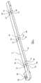
- a load handling trolley 10 has a load engager 12 of inverted channel section, so that its web 14 will be upwards to engage a load and its side walls 16, 18 will depend downwardly. Between the side walls 16, 18 and in closely adjacent clearance thereto are bogie assemblies 20.
- the bogie assemblies 20 have spaced sides 22, 24 interconnected by studs 26, rollers 28 and journalled rods 30 for articulation links 32 between bogie assemblies 20, of which there are at least two per load engager, i.e. per trolley extension unit also available under the JOLODA trade mark.
- the studs 26 also interconnect means 34 for raising and lowering the bogie assemblies situated between the bogie side walls.
- the means 34 comprises a pair of spaced walls 36 having a roller 38 mounted therebetween.
- a ramp 40 secured to the underside of the load engager 12 by screws 41, whereby, from a lowered position, movement of the bogie assemblies 20 along the load engager 12 causes the roller 38 to move over the ramp 40 to urge the load engager upwards relative to the bogie assemblies.
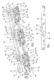
- outside faces of the sides 22, 24 of the bogie assemblies 20 have grooves 42 therein (see Figure 6), along which pins 44 on the inside faces of the load engager side walls 16,18 travel as the load engager moves upwardly or downwardly relative to the bogie assemblies.
- the grooves 42 have a first lower part 46 parallel to the lower edges of the sides 22, 24 of the bogie assemblies 20, an angled major portion 48 corresponding to the slope of the ramp 40 and an upper portion 50 parallel to the top edge of the sides of the bogie assemblies.
- the upper portion 50 occupies a projection 52 extending above the major part of the top edge of the sides of the bogie assemblies.
- the end of the lower part 46 of the groove 42 is closed, whilst the end of the upper part 50 of the groove 42 is open to allow fitting of the bogie assemblies to the load engager.
- the projections 52 of the sides of the bogie assemblies 20 are accommodated in the lowered position in apertures 54 in the top of the load engager 12, so as not to be proud thereof.
- the grooves 42 in the projections 52 allow the load engager to be raised higher than would be possible with conventional bogie assembly sides.
- a crank 56 is pivotally connected between the side walls 16, 18 of the load engager 12 to pivot about a pin 58, so as to be movable between the positions illustrated in Figures 2 and 4.
- the side walls 16, 18 of the load engager are connected by an end wall 60 and the top of the load engager at its end is open at 62 to receive an operating lever 64 that engages in hole 66 in the top of the crank 56.
- Pivotally connected at axis 67 to the crank is a pair of laterally spaced links 68.
- the pair of crank links 68 is pivotally connected to a respective one of the sides 22, 24 of the bogie assembly 20 by way of a pivot pin connection 70.
- Each crank link 68 carries a pivot pin 72, which acts as an abutment.
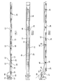
- FIG 2 the mechanism is shown with the load engager 12 in its lowered position.
- the operating lever 64 is inserted into the crank 56 and pivoted anti-clockwise in the illustrated embodiment to move the crank and thus displace the bogie assembly 20 longitudinally by action of the link.
- the displacement of the bogie assembly causes the ramp 40 to be raised by the roller 38 and hence the load engager is moved to a raised position as shown in Figure 4 of the drawings for movement of the load handling trolley along the track.
- the maximum displacement is such as to move the pins 44 along the grooves 42 to their upper portions 50.
Landscapes
- Engineering & Computer Science (AREA)
- Chemical & Material Sciences (AREA)
- Combustion & Propulsion (AREA)
- Transportation (AREA)
- Mechanical Engineering (AREA)
- Handcart (AREA)
- Platform Screen Doors And Railroad Systems (AREA)
- Chain Conveyers (AREA)
- Polymers With Sulfur, Phosphorus Or Metals In The Main Chain (AREA)
- Stored Programmes (AREA)
- Liquid Crystal (AREA)
Abstract
Description
- This invention concerns toad-handling trolleys of the type that normally run in channel tracks and comprise elongate load engagers raisable and lowerable relative to bogies via ramp-and-roller means when the engager and the bogies are caused to move longitudinally relative to each other.
- Successful and well-known examples of such trolley-in-track systems are available under the Registered Trade Mark JOLODA.
- A strong reasonably flat floor into which the tracks are let and reasonably rigid loads, such as containers or pallets, have led to remarkably low-profile trolleys in quite shallow tracks as only a small lift height has been adequate to give a free travel clearance for the load over the floor after insertion of and raising the trolley.
- There is now a tendency, dictated by seeking minimum costs of floors, pallets and containers, for floors and pallets to be less rigid, so that flexing or sagging can result in hitherto satisfactory lifting heights being insufficient always to avoid load-to-floor contact during movement of loads by the trolley.
- The success and reputation of JOLODA trolleys is based on sound and well engineered design involving, inter alia, close interfitment of bogie side walls and depending walls of inverted channel section load engagers, virtually flush bottoms of such walls in the unraised state of the trolleys, and in one design positive retention means between those side and depending walls, but the limits set by rigid pin-and-ledge, groove or slot type positive retention means preclude achievement of desired amounts of increased lift.
- Accordingly our high lift trolley utilised positive retention means that is basically characterised by including a device having one component that is anchored and at least one other relatively movable component connected thereto and coupled to a trolley part so as to move during relative movement of the engager and bogie assembly.
- It is evident that, for greater lift within the same basic trolley height, the ramp means must more nearly approach the available height of the space within the inverted channel type load engagers encompassing the bogies, though we prefer that it should remain slightly less so that positive lateral location of sides of the bogies remain even approaching and at full height of the trolley, due to overlap by the depending sides of the load engager, which are preferably closely adjacent thereto throughout their length. Lift height will usually be greater on approach if, as is preferred, the ramps have locating depressions at full height.
- More particularly we have utilised retention means in the form of spring links engaging and effectively in guiding/retaining engagement with rollers of the bogies, encompassing axles or rods thereof in a slot of the links otherwise anchored, clamped under wedges with which the rollers co-act. The basic action of such an embodiment comprises a flexing of the spring retainers for roller-axles as the bogies' rollers mount ramps of the load engager.
- It is accepted that our trolleys will inevitably be subjected to extremely rough treatment, even dropped, if not thrown onto concrete floors, and we take great pride in the fact that our trolleys can readily with stand such treatment without failure or breakage.
- In that spirit, and for such treatment, we prefer to guard against the possibility that the bogies can then be forced out of, "flirted" from, positions corresponding to design maxima, indeed extend beyond side walls of the load engager with deleterious effects, if we rely entirely upon spring links however closely such are in guiding relation with the roller axle/bogie cross-connections/bogie studs. Such guard has been afforded by inextensible limiting means for the springs links comprising a wire link extending from below the load engager ramps to the end of spring links, generally using U-shaped wire device with its bight captive under a said ramp.
- The spring links are formed for engagement adjacent each side of bogie side walls by a unitary construction of spring steel, in sheet form with a first part to be clamped under ramp parts of the bogie and parts extending to each side of a such ramp part, those extending parts being returned on themselves at a suitable distance from the first part, and, further returned after a distance corresponding to maximum displacement of their engagers, e.g. roller axles, in climbing of ramp parts, then brought back to the first return bend to define a slot corresponding to the aforesaid maximum displacement, and yet further again returned through such first return bend and then, desirably, along the first mentioned extension.
- However, an alternative to the aforesaid spring retention means and limiting means therefor was proposed in our earlier patent application
EP 1251056 to provide the desired positive retention and achieve the desired limit on movement. In the alternative it was proposed that the positive retention means comprise an anchor element fixed to the load engager and at least one other inextendable relatively movable element mounted for pivotal movement with respect to the anchor element and having a slot to receive an axle or some other cross connection of the roller means so as to move during relative movement of the engager and bogie assembly, and wherein said relatively movable component has abutment means that is cooperable with the load engager to limit articulation of the relatively movable component. - It has been found that this alternative arrangement is complicated to manufacture and the increase of parts leads to less reliability for the harsh conditions in which load handling trolleys of this type are generally used.
- An object of the invention is to provide a load handling trolley of the type described having facility for greater lift and simpler positive retention means between the engager and bogie assembly.
- According to the invention there is provided a load handling trolley of the type that normally runs in a channel led track comprising an elongate load engager having a load receiving top and depending side walls and which is raisable and lowerable relative to at least one bogie assembly via ramp and roller means when the engager and the bogie assembly are caused to move longitudinally relative to each other, wherein the bogie assembly has at least one side wall with a projection above a top edge of a major portion of its length, whereby positive retention between the load engager and the bogie assembly is still made when a bottom edge of a load engager side wall is raised to the height of said top edge of the bogie side wall and wherein the projection is accommodated by the top of the load engager when in the lowered position.
- The positive retention means preferably comprises a groove and peg arrangement between the inside of a side of the load engager and an outer side of a side of the bogie assembly. Ideally the groove will be on the bogie and the peg on the load engager.
- The projection is preferably accommodated in an aperture of the load engager top.
- The groove preferably has a major portico corresponding to the slope of the ramp. A lower portion of the groove is preferably parallel with a bottom edge of a bogie side wall. The lower portion of the groove preferably has a closed end.
- The groove preferably has an upper portion parallel with the top edge of a side wall of the bogie assembly- The upper portion of the groove preferably has an open end for fitting the bogie assembly to the load engager.
- In practice this means that the load engager can be raised a greater distance relative to the bogies than in prior art load handling trolleys of this general type.
- This invention will now be further described, by way of example only, with reference to the accompanying drawings, in which:
- Figure 1 shows a load handling trolley of the invention;
- Figure 2 is a section through the load handling trolley of Figure 1 in its lowered position;
- Figure 3 is an underside view of the trolley of Figure 1;
- Figure 4 is a section through the trolley of Figure 1. in the raised position;
- Figure 5 is an exploded view of the trolley of Figure 1; and
- Figure 6 shows a part of the trolley of Figure 1.
- Referring to the accompanying drawings, a
load handling trolley 10 has a load engager 12 of inverted channel section, so that itsweb 14 will be upwards to engage a load and itsside walls side walls bogie assemblies 20. Thebogie assemblies 20 have spacedsides studs 26,rollers 28 andjournalled rods 30 forarticulation links 32 betweenbogie assemblies 20, of which there are at least two per load engager, i.e. per trolley extension unit also available under the JOLODA trade mark. - The
studs 26 also interconnect means 34 for raising and lowering the bogie assemblies situated between the bogie side walls. Themeans 34 comprises a pair of spacedwalls 36 having aroller 38 mounted therebetween. Associated with theroller 38 is aramp 40 secured to the underside of the load engager 12 byscrews 41, whereby, from a lowered position, movement of thebogie assemblies 20 along the load engager 12 causes theroller 38 to move over theramp 40 to urge the load engager upwards relative to the bogie assemblies. - Outside faces of the
sides bogie assemblies 20 havegrooves 42 therein (see Figure 6), along whichpins 44 on the inside faces of the load engagerside walls grooves 42 have a firstlower part 46 parallel to the lower edges of thesides bogie assemblies 20, an angledmajor portion 48 corresponding to the slope of theramp 40 and anupper portion 50 parallel to the top edge of the sides of the bogie assemblies. Theupper portion 50 occupies aprojection 52 extending above the major part of the top edge of the sides of the bogie assemblies. The end of thelower part 46 of thegroove 42 is closed, whilst the end of theupper part 50 of thegroove 42 is open to allow fitting of the bogie assemblies to the load engager. - In order to provide maximum elevation of the load engager 12 relative to the
bogie assemblies 20, theprojections 52 of the sides of thebogie assemblies 20 are accommodated in the lowered position inapertures 54 in the top of the load engager 12, so as not to be proud thereof. When thebogie assemblies 20 are moved longitudinally relative to the load engager 12, thegrooves 42 in theprojections 52 allow the load engager to be raised higher than would be possible with conventional bogie assembly sides. - As shown the mechanism for moving the
bogie assemblies 20 longitudinally relative to the load engager isconventional A crank 56 is pivotally connected between theside walls pin 58, so as to be movable between the positions illustrated in Figures 2 and 4. Theside walls end wall 60 and the top of the load engager at its end is open at 62 to receive anoperating lever 64 that engages inhole 66 in the top of thecrank 56. Pivotally connected ataxis 67 to the crank is a pair of laterally spacedlinks 68. The pair ofcrank links 68 is pivotally connected to a respective one of thesides bogie assembly 20 by way of apivot pin connection 70. Eachcrank link 68 carries apivot pin 72, which acts as an abutment. - In Figure 2 the mechanism is shown with the load engager 12 in its lowered position. When it is required to elevate the load engager relative to the track the
operating lever 64 is inserted into thecrank 56 and pivoted anti-clockwise in the illustrated embodiment to move the crank and thus displace thebogie assembly 20 longitudinally by action of the link. As previously described the displacement of the bogie assembly causes theramp 40 to be raised by theroller 38 and hence the load engager is moved to a raised position as shown in Figure 4 of the drawings for movement of the load handling trolley along the track. The maximum displacement is such as to move thepins 44 along thegrooves 42 to theirupper portions 50. - Where the
rollers 28 are in contact with the track in normal operation of the load handling trolley, a clearance remains between thepin 72 and the end surface of thebogie assembly sides Abutment pin 72 would result in the considerable angular displacement between thelink 68 and thebogie assembly 20. However, by providing theabutment pin 72, angular movement is constrained and, therefore, despite the fact that the end bogie is not sufficiently supported, longitudinal movement is generated to give the desired lift by movement of theroller 38 against theramp 40.
Claims (10)
- A load handling trolley of the type that normally runs in a channel led track comprising an elongate load engager having a load receiving top and depending side walls and which is raisable and lowerable relative to at least one bogie assembly via ramp and roller means when the engager and the bogie assembly are caused to move longitudinally relative to each other, wherein the bogie assembly has at least one side wall with a projection above a top edge of a major portion of its length, whereby positive retention between the load engager and the bogie assembly is still made when a bottom edge of a load engager side wall is raised to the height of said top edge of the bogie side wall and wherein the projection is accommodated by the top of the load engager when in the lowered position.
- A load handling trolley as claimed in claim 1, wherein the positive retention means comprises a groove and peg arrangement between the inside of a side of the load engager and an outer side of a side of the bogie assembly.
- A load handling trolley as claimed in claim 2, wherein the groove is on the bogie and the peg is on the load engager.
- A load handling trolley as claimed in claim 1,2 or 3, wherein the projection is accommodated in an aperture of the load engager top.
- A load handling trolley as claimed in claim 2, 3 or 4, wherein the groove has a major portion corresponding to the slope of the ramp.
- A load handling trolley as claimed in any one of claims 2 to 5, wherein the groove has a lower portion parallel with a bottom edge of a bogie side wall.
- A load handling trolley as claimed in claim 6, wherein the lower portion of the groove has a closed end.
- A load handling trolley as claimed in any one of claims 2 to 7, wherein the groove has an upper portion parallel with the top edge of a side wall of the bogie assembly.
- A load handling trolley as claimed in any one of claims 2 to 7 wherein the upper portion of the groove has an open end.
- A load handling trolley substantially as hereinbefore described with reference to and as illustrated in the accompanying drawings.
Applications Claiming Priority (1)
| Application Number | Priority Date | Filing Date | Title |
|---|---|---|---|
| GBGB0617661.4A GB0617661D0 (en) | 2006-09-08 | 2006-09-08 | Load handling trolley |
Publications (3)
| Publication Number | Publication Date |
|---|---|
| EP1897749A2 true EP1897749A2 (en) | 2008-03-12 |
| EP1897749A3 EP1897749A3 (en) | 2009-09-02 |
| EP1897749B1 EP1897749B1 (en) | 2011-11-09 |
Family
ID=37232564
Family Applications (1)
| Application Number | Title | Priority Date | Filing Date |
|---|---|---|---|
| EP07253544A Active EP1897749B1 (en) | 2006-09-08 | 2007-09-07 | Load handling trolley |
Country Status (4)
| Country | Link |
|---|---|
| EP (1) | EP1897749B1 (en) |
| JP (1) | JP5201918B2 (en) |
| AT (1) | ATE532669T1 (en) |
| GB (1) | GB0617661D0 (en) |
Cited By (2)
| Publication number | Priority date | Publication date | Assignee | Title |
|---|---|---|---|---|
| EP2581292A1 (en) | 2011-10-11 | 2013-04-17 | Blackrock Engineering Limited | Load handling trolley |
| WO2018081741A1 (en) * | 2016-10-31 | 2018-05-03 | Innovative Logistics, Inc. | Skate system and movable platform |
Families Citing this family (1)
| Publication number | Priority date | Publication date | Assignee | Title |
|---|---|---|---|---|
| JP6336366B2 (en) * | 2014-09-25 | 2018-06-06 | オールセーフ株式会社 | Cargo truck |
Family Cites Families (4)
| Publication number | Priority date | Publication date | Assignee | Title |
|---|---|---|---|---|
| GB8320591D0 (en) * | 1983-07-30 | 1983-09-01 | Joloda Loading Systems Ltd | Load handling trolley |
| MX159453A (en) * | 1983-07-30 | 1989-06-09 | Joloda Loading Systems Ltd | A TROLLEY TO HANDLE LOAD |
| GB0109192D0 (en) * | 2001-04-12 | 2001-05-30 | Blackrock Engineering Ltd | Improvements in and relating to load handling skates |
| GB0109702D0 (en) * | 2001-04-20 | 2001-06-13 | Blackrock Engineering Ltd | Load handling trolley |
-
2006
- 2006-09-08 GB GBGB0617661.4A patent/GB0617661D0/en not_active Ceased
-
2007
- 2007-09-07 EP EP07253544A patent/EP1897749B1/en active Active
- 2007-09-07 AT AT07253544T patent/ATE532669T1/en active
- 2007-09-10 JP JP2007234683A patent/JP5201918B2/en active Active
Cited By (3)
| Publication number | Priority date | Publication date | Assignee | Title |
|---|---|---|---|---|
| EP2581292A1 (en) | 2011-10-11 | 2013-04-17 | Blackrock Engineering Limited | Load handling trolley |
| WO2018081741A1 (en) * | 2016-10-31 | 2018-05-03 | Innovative Logistics, Inc. | Skate system and movable platform |
| US10618753B2 (en) | 2016-10-31 | 2020-04-14 | Innovative Logistics, Inc. | Skate system and movable platform |
Also Published As
| Publication number | Publication date |
|---|---|
| ATE532669T1 (en) | 2011-11-15 |
| GB0617661D0 (en) | 2006-10-18 |
| EP1897749B1 (en) | 2011-11-09 |
| JP5201918B2 (en) | 2013-06-05 |
| JP2008189464A (en) | 2008-08-21 |
| EP1897749A3 (en) | 2009-09-02 |
Similar Documents
| Publication | Publication Date | Title |
|---|---|---|
| CN101678833B (en) | Transporting device using a trolley | |
| US11034276B2 (en) | Auxiliary convey mechanism for goods in a vehicle compartment | |
| CA2745152C (en) | Dock leveler | |
| EP1897749B1 (en) | Load handling trolley | |
| EP0133042B1 (en) | Load handling trolley | |
| KR20230083508A (en) | A portable cart for loading cargo | |
| US5975495A (en) | Lift | |
| US20180155170A1 (en) | High-lift industrial truck | |
| CN100526138C (en) | Carrying apparatus with lifting carried object support table | |
| EP2581292B1 (en) | Load handling trolley | |
| EP0684175A1 (en) | Load handling trolley | |
| EP1251056A1 (en) | Load handling trolley | |
| KR101324543B1 (en) | Traveling braking apparatus of unloader | |
| JP6336366B2 (en) | Cargo truck | |
| KR20060008653A (en) | Fork parking facility using a movable pallet | |
| EP1136402A2 (en) | Load handling apparatus | |
| KR100820086B1 (en) | Two way emergency stop device in elevator | |
| JPH0840512A (en) | Goods storage facility | |
| KR200401386Y1 (en) | Safety device for an elevator | |
| GB2144100A (en) | Load handling trolley | |
| JPS6111121Y2 (en) | ||
| CN206749831U (en) | A kind of assembled mainboard transport vehicle | |
| CA1311206C (en) | Conveyor, in particular for heavy objects | |
| JP2000177998A (en) | Vehicle bed leveling device | |
| JP2005163311A (en) | Simultaneous elevator type parking system |
Legal Events
| Date | Code | Title | Description |
|---|---|---|---|
| PUAI | Public reference made under article 153(3) epc to a published international application that has entered the european phase |
Free format text: ORIGINAL CODE: 0009012 |
|
| AK | Designated contracting states |
Kind code of ref document: A2 Designated state(s): AT BE BG CH CY CZ DE DK EE ES FI FR GB GR HU IE IS IT LI LT LU LV MC MT NL PL PT RO SE SI SK TR |
|
| AX | Request for extension of the european patent |
Extension state: AL BA HR MK YU |
|
| PUAL | Search report despatched |
Free format text: ORIGINAL CODE: 0009013 |
|
| AK | Designated contracting states |
Kind code of ref document: A3 Designated state(s): AT BE BG CH CY CZ DE DK EE ES FI FR GB GR HU IE IS IT LI LT LU LV MC MT NL PL PT RO SE SI SK TR |
|
| AX | Request for extension of the european patent |
Extension state: AL BA HR MK RS |
|
| 17P | Request for examination filed |
Effective date: 20100112 |
|
| 17Q | First examination report despatched |
Effective date: 20100208 |
|
| AKX | Designation fees paid |
Designated state(s): AT BE BG CH CY CZ DE DK EE ES FI FR GB GR HU IE IS IT LI LT LU LV MC MT NL PL PT RO SE SI SK TR |
|
| GRAP | Despatch of communication of intention to grant a patent |
Free format text: ORIGINAL CODE: EPIDOSNIGR1 |
|
| GRAS | Grant fee paid |
Free format text: ORIGINAL CODE: EPIDOSNIGR3 |
|
| GRAA | (expected) grant |
Free format text: ORIGINAL CODE: 0009210 |
|
| AK | Designated contracting states |
Kind code of ref document: B1 Designated state(s): AT BE BG CH CY CZ DE DK EE ES FI FR GB GR HU IE IS IT LI LT LU LV MC MT NL PL PT RO SE SI SK TR |
|
| REG | Reference to a national code |
Ref country code: GB Ref legal event code: FG4D |
|
| REG | Reference to a national code |
Ref country code: CH Ref legal event code: EP |
|
| REG | Reference to a national code |
Ref country code: IE Ref legal event code: FG4D |
|
| REG | Reference to a national code |
Ref country code: DE Ref legal event code: R096 Ref document number: 602007018581 Country of ref document: DE Effective date: 20120119 |
|
| REG | Reference to a national code |
Ref country code: RO Ref legal event code: EPE |
|
| REG | Reference to a national code |
Ref country code: NL Ref legal event code: T3 |
|
| LTIE | Lt: invalidation of european patent or patent extension |
Effective date: 20111109 |
|
| PG25 | Lapsed in a contracting state [announced via postgrant information from national office to epo] |
Ref country code: LT Free format text: LAPSE BECAUSE OF FAILURE TO SUBMIT A TRANSLATION OF THE DESCRIPTION OR TO PAY THE FEE WITHIN THE PRESCRIBED TIME-LIMIT Effective date: 20111109 Ref country code: IS Free format text: LAPSE BECAUSE OF FAILURE TO SUBMIT A TRANSLATION OF THE DESCRIPTION OR TO PAY THE FEE WITHIN THE PRESCRIBED TIME-LIMIT Effective date: 20120309 |
|
| PG25 | Lapsed in a contracting state [announced via postgrant information from national office to epo] |
Ref country code: LV Free format text: LAPSE BECAUSE OF FAILURE TO SUBMIT A TRANSLATION OF THE DESCRIPTION OR TO PAY THE FEE WITHIN THE PRESCRIBED TIME-LIMIT Effective date: 20111109 Ref country code: GR Free format text: LAPSE BECAUSE OF FAILURE TO SUBMIT A TRANSLATION OF THE DESCRIPTION OR TO PAY THE FEE WITHIN THE PRESCRIBED TIME-LIMIT Effective date: 20120210 Ref country code: SE Free format text: LAPSE BECAUSE OF FAILURE TO SUBMIT A TRANSLATION OF THE DESCRIPTION OR TO PAY THE FEE WITHIN THE PRESCRIBED TIME-LIMIT Effective date: 20111109 Ref country code: SI Free format text: LAPSE BECAUSE OF FAILURE TO SUBMIT A TRANSLATION OF THE DESCRIPTION OR TO PAY THE FEE WITHIN THE PRESCRIBED TIME-LIMIT Effective date: 20111109 Ref country code: PL Free format text: LAPSE BECAUSE OF FAILURE TO SUBMIT A TRANSLATION OF THE DESCRIPTION OR TO PAY THE FEE WITHIN THE PRESCRIBED TIME-LIMIT Effective date: 20111109 Ref country code: PT Free format text: LAPSE BECAUSE OF FAILURE TO SUBMIT A TRANSLATION OF THE DESCRIPTION OR TO PAY THE FEE WITHIN THE PRESCRIBED TIME-LIMIT Effective date: 20120309 |
|
| PG25 | Lapsed in a contracting state [announced via postgrant information from national office to epo] |
Ref country code: CY Free format text: LAPSE BECAUSE OF FAILURE TO SUBMIT A TRANSLATION OF THE DESCRIPTION OR TO PAY THE FEE WITHIN THE PRESCRIBED TIME-LIMIT Effective date: 20111109 |
|
| PG25 | Lapsed in a contracting state [announced via postgrant information from national office to epo] |
Ref country code: BG Free format text: LAPSE BECAUSE OF FAILURE TO SUBMIT A TRANSLATION OF THE DESCRIPTION OR TO PAY THE FEE WITHIN THE PRESCRIBED TIME-LIMIT Effective date: 20120209 Ref country code: EE Free format text: LAPSE BECAUSE OF FAILURE TO SUBMIT A TRANSLATION OF THE DESCRIPTION OR TO PAY THE FEE WITHIN THE PRESCRIBED TIME-LIMIT Effective date: 20111109 Ref country code: DK Free format text: LAPSE BECAUSE OF FAILURE TO SUBMIT A TRANSLATION OF THE DESCRIPTION OR TO PAY THE FEE WITHIN THE PRESCRIBED TIME-LIMIT Effective date: 20111109 Ref country code: CZ Free format text: LAPSE BECAUSE OF FAILURE TO SUBMIT A TRANSLATION OF THE DESCRIPTION OR TO PAY THE FEE WITHIN THE PRESCRIBED TIME-LIMIT Effective date: 20111109 Ref country code: SK Free format text: LAPSE BECAUSE OF FAILURE TO SUBMIT A TRANSLATION OF THE DESCRIPTION OR TO PAY THE FEE WITHIN THE PRESCRIBED TIME-LIMIT Effective date: 20111109 |
|
| PG25 | Lapsed in a contracting state [announced via postgrant information from national office to epo] |
Ref country code: IT Free format text: LAPSE BECAUSE OF FAILURE TO SUBMIT A TRANSLATION OF THE DESCRIPTION OR TO PAY THE FEE WITHIN THE PRESCRIBED TIME-LIMIT Effective date: 20111109 |
|
| PLBE | No opposition filed within time limit |
Free format text: ORIGINAL CODE: 0009261 |
|
| STAA | Information on the status of an ep patent application or granted ep patent |
Free format text: STATUS: NO OPPOSITION FILED WITHIN TIME LIMIT |
|
| 26N | No opposition filed |
Effective date: 20120810 |
|
| REG | Reference to a national code |
Ref country code: DE Ref legal event code: R097 Ref document number: 602007018581 Country of ref document: DE Effective date: 20120810 |
|
| PGFP | Annual fee paid to national office [announced via postgrant information from national office to epo] |
Ref country code: FR Payment date: 20121204 Year of fee payment: 6 |
|
| PGFP | Annual fee paid to national office [announced via postgrant information from national office to epo] |
Ref country code: GB Payment date: 20121010 Year of fee payment: 6 |
|
| PG25 | Lapsed in a contracting state [announced via postgrant information from national office to epo] |
Ref country code: MC Free format text: LAPSE BECAUSE OF NON-PAYMENT OF DUE FEES Effective date: 20120930 Ref country code: ES Free format text: LAPSE BECAUSE OF FAILURE TO SUBMIT A TRANSLATION OF THE DESCRIPTION OR TO PAY THE FEE WITHIN THE PRESCRIBED TIME-LIMIT Effective date: 20120220 |
|
| REG | Reference to a national code |
Ref country code: CH Ref legal event code: PL |
|
| REG | Reference to a national code |
Ref country code: IE Ref legal event code: MM4A |
|
| PG25 | Lapsed in a contracting state [announced via postgrant information from national office to epo] |
Ref country code: FI Free format text: LAPSE BECAUSE OF FAILURE TO SUBMIT A TRANSLATION OF THE DESCRIPTION OR TO PAY THE FEE WITHIN THE PRESCRIBED TIME-LIMIT Effective date: 20111109 |
|
| PG25 | Lapsed in a contracting state [announced via postgrant information from national office to epo] |
Ref country code: CH Free format text: LAPSE BECAUSE OF NON-PAYMENT OF DUE FEES Effective date: 20120930 Ref country code: IE Free format text: LAPSE BECAUSE OF NON-PAYMENT OF DUE FEES Effective date: 20120907 Ref country code: LI Free format text: LAPSE BECAUSE OF NON-PAYMENT OF DUE FEES Effective date: 20120930 |
|
| PG25 | Lapsed in a contracting state [announced via postgrant information from national office to epo] |
Ref country code: MT Free format text: LAPSE BECAUSE OF FAILURE TO SUBMIT A TRANSLATION OF THE DESCRIPTION OR TO PAY THE FEE WITHIN THE PRESCRIBED TIME-LIMIT Effective date: 20111109 |
|
| PG25 | Lapsed in a contracting state [announced via postgrant information from national office to epo] |
Ref country code: RO Free format text: LAPSE BECAUSE OF NON-PAYMENT OF DUE FEES Effective date: 20130907 Ref country code: TR Free format text: LAPSE BECAUSE OF FAILURE TO SUBMIT A TRANSLATION OF THE DESCRIPTION OR TO PAY THE FEE WITHIN THE PRESCRIBED TIME-LIMIT Effective date: 20111109 |
|
| GBPC | Gb: european patent ceased through non-payment of renewal fee |
Effective date: 20130907 |
|
| PG25 | Lapsed in a contracting state [announced via postgrant information from national office to epo] |
Ref country code: LU Free format text: LAPSE BECAUSE OF NON-PAYMENT OF DUE FEES Effective date: 20120907 |
|
| REG | Reference to a national code |
Ref country code: FR Ref legal event code: ST Effective date: 20140530 |
|
| PG25 | Lapsed in a contracting state [announced via postgrant information from national office to epo] |
Ref country code: GB Free format text: LAPSE BECAUSE OF NON-PAYMENT OF DUE FEES Effective date: 20130907 Ref country code: HU Free format text: LAPSE BECAUSE OF FAILURE TO SUBMIT A TRANSLATION OF THE DESCRIPTION OR TO PAY THE FEE WITHIN THE PRESCRIBED TIME-LIMIT Effective date: 20070907 |
|
| PG25 | Lapsed in a contracting state [announced via postgrant information from national office to epo] |
Ref country code: FR Free format text: LAPSE BECAUSE OF NON-PAYMENT OF DUE FEES Effective date: 20130930 |
|
| PGFP | Annual fee paid to national office [announced via postgrant information from national office to epo] |
Ref country code: NL Payment date: 20250930 Year of fee payment: 19 |
|
| PGFP | Annual fee paid to national office [announced via postgrant information from national office to epo] |
Ref country code: AT Payment date: 20251001 Year of fee payment: 19 |
|
| PGFP | Annual fee paid to national office [announced via postgrant information from national office to epo] |
Ref country code: DE Payment date: 20251002 Year of fee payment: 19 |
|
| PGFP | Annual fee paid to national office [announced via postgrant information from national office to epo] |
Ref country code: BE Payment date: 20250930 Year of fee payment: 19 |