EP2581200A2 - Verfahren zur Herstellung einer Komponente zur Verbindung von Strukturen sowie Vorrichtung - Google Patents
Verfahren zur Herstellung einer Komponente zur Verbindung von Strukturen sowie Vorrichtung Download PDFInfo
- Publication number
- EP2581200A2 EP2581200A2 EP20120188065 EP12188065A EP2581200A2 EP 2581200 A2 EP2581200 A2 EP 2581200A2 EP 20120188065 EP20120188065 EP 20120188065 EP 12188065 A EP12188065 A EP 12188065A EP 2581200 A2 EP2581200 A2 EP 2581200A2
- Authority
- EP
- European Patent Office
- Prior art keywords
- fibres
- fibre
- another
- component
- longitudinal direction
- Prior art date
- Legal status (The legal status is an assumption and is not a legal conclusion. Google has not performed a legal analysis and makes no representation as to the accuracy of the status listed.)
- Granted
Links
- 238000004519 manufacturing process Methods 0.000 title claims abstract description 9
- 239000000835 fiber Substances 0.000 claims abstract description 76
- 238000000151 deposition Methods 0.000 claims abstract description 11
- 238000000034 method Methods 0.000 claims description 33
- 229920001169 thermoplastic Polymers 0.000 claims description 10
- 239000004416 thermosoftening plastic Substances 0.000 claims description 10
- 239000000853 adhesive Substances 0.000 claims description 9
- 230000001070 adhesive effect Effects 0.000 claims description 9
- 238000004026 adhesive bonding Methods 0.000 claims description 7
- 238000009954 braiding Methods 0.000 claims description 7
- 238000009941 weaving Methods 0.000 claims description 7
- 239000000109 continuous material Substances 0.000 claims description 5
- 239000012815 thermoplastic material Substances 0.000 claims description 5
- 239000002131 composite material Substances 0.000 description 3
- 238000005520 cutting process Methods 0.000 description 3
- 239000002184 metal Substances 0.000 description 2
- 238000009745 resin transfer moulding Methods 0.000 description 2
- OKTJSMMVPCPJKN-UHFFFAOYSA-N Carbon Chemical compound [C] OKTJSMMVPCPJKN-UHFFFAOYSA-N 0.000 description 1
- 238000005452 bending Methods 0.000 description 1
- 230000005540 biological transmission Effects 0.000 description 1
- 229910052799 carbon Inorganic materials 0.000 description 1
- 238000010276 construction Methods 0.000 description 1
- 230000008878 coupling Effects 0.000 description 1
- 238000010168 coupling process Methods 0.000 description 1
- 238000005859 coupling reaction Methods 0.000 description 1
- 239000003292 glue Substances 0.000 description 1
- 239000000463 material Substances 0.000 description 1
- 239000011159 matrix material Substances 0.000 description 1
- 239000004033 plastic Substances 0.000 description 1
- 229920003023 plastic Polymers 0.000 description 1
- 229920001187 thermosetting polymer Polymers 0.000 description 1
Images


Classifications
-
- B—PERFORMING OPERATIONS; TRANSPORTING
- B29—WORKING OF PLASTICS; WORKING OF SUBSTANCES IN A PLASTIC STATE IN GENERAL
- B29C—SHAPING OR JOINING OF PLASTICS; SHAPING OF MATERIAL IN A PLASTIC STATE, NOT OTHERWISE PROVIDED FOR; AFTER-TREATMENT OF THE SHAPED PRODUCTS, e.g. REPAIRING
- B29C70/00—Shaping composites, i.e. plastics material comprising reinforcements, fillers or preformed parts, e.g. inserts
- B29C70/68—Shaping composites, i.e. plastics material comprising reinforcements, fillers or preformed parts, e.g. inserts by incorporating or moulding on preformed parts, e.g. inserts or layers, e.g. foam blocks
- B29C70/74—Moulding material on a relatively small portion of the preformed part, e.g. outsert moulding
- B29C70/76—Moulding on edges or extremities of the preformed part
-
- D—TEXTILES; PAPER
- D04—BRAIDING; LACE-MAKING; KNITTING; TRIMMINGS; NON-WOVEN FABRICS
- D04H—MAKING TEXTILE FABRICS, e.g. FROM FIBRES OR FILAMENTARY MATERIAL; FABRICS MADE BY SUCH PROCESSES OR APPARATUS, e.g. FELTS, NON-WOVEN FABRICS; COTTON-WOOL; WADDING ; NON-WOVEN FABRICS FROM STAPLE FIBRES, FILAMENTS OR YARNS, BONDED WITH AT LEAST ONE WEB-LIKE MATERIAL DURING THEIR CONSOLIDATION
- D04H1/00—Non-woven fabrics formed wholly or mainly of staple fibres or like relatively short fibres
-
- B—PERFORMING OPERATIONS; TRANSPORTING
- B29—WORKING OF PLASTICS; WORKING OF SUBSTANCES IN A PLASTIC STATE IN GENERAL
- B29C—SHAPING OR JOINING OF PLASTICS; SHAPING OF MATERIAL IN A PLASTIC STATE, NOT OTHERWISE PROVIDED FOR; AFTER-TREATMENT OF THE SHAPED PRODUCTS, e.g. REPAIRING
- B29C70/00—Shaping composites, i.e. plastics material comprising reinforcements, fillers or preformed parts, e.g. inserts
- B29C70/04—Shaping composites, i.e. plastics material comprising reinforcements, fillers or preformed parts, e.g. inserts comprising reinforcements only, e.g. self-reinforcing plastics
- B29C70/06—Fibrous reinforcements only
- B29C70/10—Fibrous reinforcements only characterised by the structure of fibrous reinforcements, e.g. hollow fibres
- B29C70/12—Fibrous reinforcements only characterised by the structure of fibrous reinforcements, e.g. hollow fibres using fibres of short length, e.g. in the form of a mat
- B29C70/14—Fibrous reinforcements only characterised by the structure of fibrous reinforcements, e.g. hollow fibres using fibres of short length, e.g. in the form of a mat oriented
-
- B—PERFORMING OPERATIONS; TRANSPORTING
- B29—WORKING OF PLASTICS; WORKING OF SUBSTANCES IN A PLASTIC STATE IN GENERAL
- B29C—SHAPING OR JOINING OF PLASTICS; SHAPING OF MATERIAL IN A PLASTIC STATE, NOT OTHERWISE PROVIDED FOR; AFTER-TREATMENT OF THE SHAPED PRODUCTS, e.g. REPAIRING
- B29C70/00—Shaping composites, i.e. plastics material comprising reinforcements, fillers or preformed parts, e.g. inserts
- B29C70/04—Shaping composites, i.e. plastics material comprising reinforcements, fillers or preformed parts, e.g. inserts comprising reinforcements only, e.g. self-reinforcing plastics
- B29C70/06—Fibrous reinforcements only
- B29C70/10—Fibrous reinforcements only characterised by the structure of fibrous reinforcements, e.g. hollow fibres
- B29C70/16—Fibrous reinforcements only characterised by the structure of fibrous reinforcements, e.g. hollow fibres using fibres of substantial or continuous length
- B29C70/20—Fibrous reinforcements only characterised by the structure of fibrous reinforcements, e.g. hollow fibres using fibres of substantial or continuous length oriented in a single direction, e.g. roofing or other parallel fibres
- B29C70/205—Fibrous reinforcements only characterised by the structure of fibrous reinforcements, e.g. hollow fibres using fibres of substantial or continuous length oriented in a single direction, e.g. roofing or other parallel fibres the structure being shaped to form a three-dimensional configuration
-
- B—PERFORMING OPERATIONS; TRANSPORTING
- B29—WORKING OF PLASTICS; WORKING OF SUBSTANCES IN A PLASTIC STATE IN GENERAL
- B29C—SHAPING OR JOINING OF PLASTICS; SHAPING OF MATERIAL IN A PLASTIC STATE, NOT OTHERWISE PROVIDED FOR; AFTER-TREATMENT OF THE SHAPED PRODUCTS, e.g. REPAIRING
- B29C70/00—Shaping composites, i.e. plastics material comprising reinforcements, fillers or preformed parts, e.g. inserts
- B29C70/04—Shaping composites, i.e. plastics material comprising reinforcements, fillers or preformed parts, e.g. inserts comprising reinforcements only, e.g. self-reinforcing plastics
- B29C70/06—Fibrous reinforcements only
- B29C70/10—Fibrous reinforcements only characterised by the structure of fibrous reinforcements, e.g. hollow fibres
- B29C70/16—Fibrous reinforcements only characterised by the structure of fibrous reinforcements, e.g. hollow fibres using fibres of substantial or continuous length
- B29C70/22—Fibrous reinforcements only characterised by the structure of fibrous reinforcements, e.g. hollow fibres using fibres of substantial or continuous length oriented in at least two directions forming a two dimensional structure
- B29C70/222—Fibrous reinforcements only characterised by the structure of fibrous reinforcements, e.g. hollow fibres using fibres of substantial or continuous length oriented in at least two directions forming a two dimensional structure the structure being shaped to form a three dimensional configuration
-
- B—PERFORMING OPERATIONS; TRANSPORTING
- B29—WORKING OF PLASTICS; WORKING OF SUBSTANCES IN A PLASTIC STATE IN GENERAL
- B29C—SHAPING OR JOINING OF PLASTICS; SHAPING OF MATERIAL IN A PLASTIC STATE, NOT OTHERWISE PROVIDED FOR; AFTER-TREATMENT OF THE SHAPED PRODUCTS, e.g. REPAIRING
- B29C70/00—Shaping composites, i.e. plastics material comprising reinforcements, fillers or preformed parts, e.g. inserts
- B29C70/04—Shaping composites, i.e. plastics material comprising reinforcements, fillers or preformed parts, e.g. inserts comprising reinforcements only, e.g. self-reinforcing plastics
- B29C70/06—Fibrous reinforcements only
- B29C70/10—Fibrous reinforcements only characterised by the structure of fibrous reinforcements, e.g. hollow fibres
- B29C70/16—Fibrous reinforcements only characterised by the structure of fibrous reinforcements, e.g. hollow fibres using fibres of substantial or continuous length
- B29C70/24—Fibrous reinforcements only characterised by the structure of fibrous reinforcements, e.g. hollow fibres using fibres of substantial or continuous length oriented in at least three directions forming a three dimensional structure
-
- D—TEXTILES; PAPER
- D03—WEAVING
- D03D—WOVEN FABRICS; METHODS OF WEAVING; LOOMS
- D03D1/00—Woven fabrics designed to make specified articles
-
- D—TEXTILES; PAPER
- D03—WEAVING
- D03D—WOVEN FABRICS; METHODS OF WEAVING; LOOMS
- D03D25/00—Woven fabrics not otherwise provided for
- D03D25/005—Three-dimensional woven fabrics
-
- D—TEXTILES; PAPER
- D03—WEAVING
- D03D—WOVEN FABRICS; METHODS OF WEAVING; LOOMS
- D03D3/00—Woven fabrics characterised by their shape
-
- B—PERFORMING OPERATIONS; TRANSPORTING
- B64—AIRCRAFT; AVIATION; COSMONAUTICS
- B64C—AEROPLANES; HELICOPTERS
- B64C1/00—Fuselages; Constructional features common to fuselages, wings, stabilising surfaces or the like
- B64C1/26—Attaching the wing or tail units or stabilising surfaces
-
- B—PERFORMING OPERATIONS; TRANSPORTING
- B64—AIRCRAFT; AVIATION; COSMONAUTICS
- B64C—AEROPLANES; HELICOPTERS
- B64C9/00—Adjustable control surfaces or members, e.g. rudders
- B64C9/02—Mounting or supporting thereof
-
- D—TEXTILES; PAPER
- D10—INDEXING SCHEME ASSOCIATED WITH SUBLASSES OF SECTION D, RELATING TO TEXTILES
- D10B—INDEXING SCHEME ASSOCIATED WITH SUBLASSES OF SECTION D, RELATING TO TEXTILES
- D10B2505/00—Industrial
- D10B2505/02—Reinforcing materials; Prepregs
-
- D—TEXTILES; PAPER
- D10—INDEXING SCHEME ASSOCIATED WITH SUBLASSES OF SECTION D, RELATING TO TEXTILES
- D10B—INDEXING SCHEME ASSOCIATED WITH SUBLASSES OF SECTION D, RELATING TO TEXTILES
- D10B2505/00—Industrial
- D10B2505/12—Vehicles
-
- Y—GENERAL TAGGING OF NEW TECHNOLOGICAL DEVELOPMENTS; GENERAL TAGGING OF CROSS-SECTIONAL TECHNOLOGIES SPANNING OVER SEVERAL SECTIONS OF THE IPC; TECHNICAL SUBJECTS COVERED BY FORMER USPC CROSS-REFERENCE ART COLLECTIONS [XRACs] AND DIGESTS
- Y02—TECHNOLOGIES OR APPLICATIONS FOR MITIGATION OR ADAPTATION AGAINST CLIMATE CHANGE
- Y02T—CLIMATE CHANGE MITIGATION TECHNOLOGIES RELATED TO TRANSPORTATION
- Y02T50/00—Aeronautics or air transport
- Y02T50/40—Weight reduction
-
- Y—GENERAL TAGGING OF NEW TECHNOLOGICAL DEVELOPMENTS; GENERAL TAGGING OF CROSS-SECTIONAL TECHNOLOGIES SPANNING OVER SEVERAL SECTIONS OF THE IPC; TECHNICAL SUBJECTS COVERED BY FORMER USPC CROSS-REFERENCE ART COLLECTIONS [XRACs] AND DIGESTS
- Y10—TECHNICAL SUBJECTS COVERED BY FORMER USPC
- Y10T—TECHNICAL SUBJECTS COVERED BY FORMER US CLASSIFICATION
- Y10T29/00—Metal working
- Y10T29/49—Method of mechanical manufacture
- Y10T29/49616—Structural member making
- Y10T29/49622—Vehicular structural member making
-
- Y—GENERAL TAGGING OF NEW TECHNOLOGICAL DEVELOPMENTS; GENERAL TAGGING OF CROSS-SECTIONAL TECHNOLOGIES SPANNING OVER SEVERAL SECTIONS OF THE IPC; TECHNICAL SUBJECTS COVERED BY FORMER USPC CROSS-REFERENCE ART COLLECTIONS [XRACs] AND DIGESTS
- Y10—TECHNICAL SUBJECTS COVERED BY FORMER USPC
- Y10T—TECHNICAL SUBJECTS COVERED BY FORMER US CLASSIFICATION
- Y10T29/00—Metal working
- Y10T29/49—Method of mechanical manufacture
- Y10T29/49801—Shaping fiber or fibered material
Definitions
- the present invention relates to a method for producing a component for connecting structures, a method for producing a structural arrangement and a device for producing a component.
- Fig. 1 shows a detail from an aircraft designated 100 in general according to the prior art.
- the aircraft 100 comprises a landing flap 102.
- Fig. 1 shows the landing flap 102 counter to the flight direction of the aircraft 100.
- the landing flap 102 is shown once in a dashed view, which corresponds to its unloaded state.
- the landing flap 102 is furthermore shown by a continuous line, which corresponds to its state shown greatly exaggerated and deformed because of air loads 104.
- the landing flap 102 is connected by means of two flap carriages 106, 108 to a wing 110, which is only schematically indicated.
- the flap carriages 106, 108 allow an adjustment of the landing flap 102 with respect to the wing 110 from a flight position into a take-off or landing position, the take-off and landing position serving to increase the lift.
- one flap carriage 106 is configured as a fixed bearing and the other flap carriage 108 as a loose bearing.
- the flap carriages 106, 108 are in each case connected by an eye-pin connection 112 to the landing flap 102.
- load introduction elements such as, for example, the above-described eye of the eye-pin connection 112
- fibre composite materials for example carbon fibre plastics material (CFRP)
- CFRP carbon fibre plastics material
- US 2010/0148008 A1 describes a corresponding load introduction element made of fibre composite material, which is produced by an RTM (resin transfer moulding) method.
- the object of the present invention is to disclose a method for simple production of a component, in particular the load introduction element described above, a method for simple production of a structural arrangement and a device for simple production of the component.
- a method for producing a component for connecting structures at crossing regions thereof having the following steps: depositing first and second fibres on an underlay, in such a way that a respective first fibre has an offset in the longitudinal direction of the first or second fibre with respect to a respective second fibre, connecting the first and second fibre along an overlap region, in which the first and second fibres overlap, and pivoting the first and second fibres with respect to one another to form the component.
- a method for producing a structural arrangement having the following steps: providing a first structure, providing a second structure, which forms a crossing region with the first structure, producing a component by the method according to the invention and connecting the first and second structure in the crossing region by means of the component.
- a device for producing a component for connecting structures at crossing regions thereof, in particular for carrying out the method according to the invention, with an underlay, a depositing mechanism to deposit the first and second fibres on the underlay, in that a respective first fibre has an offset in the longitudinal direction of the first or second fibre with respect to a respective second fibre, a connecting mechanism to connect the first and second fibres along an overlap region, in which the first and second fibres overlap, and a pivoting mechanism for pivoting the first and second fibres with respect to one another to form the component.
- the idea on which the present invention is based consists in that a component with an approximately cruciform cross-section can easily be produced, in which the first and second fibres are pivoted relative to one another. After the pivoting, the first fibres intersect with the second fibres at a crossing point. The first fibres then extend, for example, substantially horizontally through the crossing point and the second fibres extend, for example, substantially perpendicularly. If the component thus provided is integrated in a structural arrangement, in particular in the landing flap described at the outset, the latter can provide two substantially mutually independent load paths through the crossing point: the first load path leads along the first fibres and the second load path leads along the second fibres.
- the use of the methods and the device is not restricted to the field of air or space travel.
- these may also be used in the area of producing bridges, multi-storey buildings, masts, roofs or other planar supporting structures.
- Fiber preferably comprises both a single fibre and a fibre tow of individual fibres.
- the first and second fibres are preferably deposited parallel to one another on the underlay. If, in the present case, “parallel” is referred to, deviations from this of up to 30 degrees, preferably up to 10 degrees, still more preferably up to 2 degrees, are also meant.
- the first fibres are connected to one another in a first projection region, in which they project in the longitudinal direction over the second fibres, and/or the second fibres are connected to one another in a second projection region, in which they project in the longitudinal direction over the first fibres.
- the first and second fibres are connected to one another in the overlap region along a centre line, which is arranged centrally in relation to a total extent of the first and second fibres in the longitudinal direction, and/or the first fibres are connected to one another in the first projection region along a first line parallel to the centre line and/or the second fibres are connected to one another along a second line parallel to the centre line and opposing the first line in relation to the centre line.
- This type of fastening of the fibres can be produced easily, in particular in an automated manner, because it is substantially linear.
- the first and second fibres are connected to one another in the overlap region, the first fibres are connected to one another in the first projection region and/or the second fibres are connected to one another in the second projection region by means of stitching, weaving, braiding or gluing.
- the stitching, weaving, braiding and gluing can easily be automated.
- At least one stitching, weaving or braiding fibre is fed through a gap in the underlay.
- a lower fibre bottom thread
- the gluing takes place by means of a thermoplastic strand, a fibre sheathed at least in portions with a thermoplastic material, or an adhesive strip.
- the thermoplastic strand, the fibre and the adhesive strip may, for example, be easily laid along the first or second line and/or the centre line in order to thereby glue them to the first and/or second fibre.
- the first and second fibres are pivoted with respect to one another in such a way that the latter have an angle of 30 to 90 degrees, preferably 60 to 90 degrees, more preferably 80 to 90 degrees, still more preferably 90 degrees, with respect to one another, and/or the pivoting of the first and second fibres with respect to one another is brought about by means of a curved guide element, past which the first and/or second fibres are guided.
- the component can easily be produced with a cruciform cross-section.
- the underlay is configured as a conveyor belt, on which the first and second fibres are deposited.
- the first and second fibres can move past the connecting mechanism in an automated manner, so an efficient method is ensured.
- the first and second fibres are in each case cut to length from continuous material before the depositing.
- the efficiency of the method can also be increased.
- the underlay has a plurality of parts, which, between them, define at least one gap, through which at least one stitching, weaving or braiding fibre can be fed to connect the first and/or the second fibre.
- the connecting mechanism is set up to connect the first fibres to one another in a first projection region, in which they project in the longitudinal direction over the second fibres, and/or to connect the second fibres to one another in a second projection region, in which they project in the longitudinal direction over the first fibres.
- the connecting mechanism may be guided, in particular, by a robot hand.
- the connecting mechanism comprises at least one stitching needle, by means of which the first fibres, second fibres and/or the first and second fibres can be stitched to one another.
- the pivoting mechanism has a curved guide path to guide the first and/or second fibre past and to pivot them.
- the guide path is, in particular, configured as a guide rail.
- Fig. 2 shows a partially perspective view of a structural arrangement 200 according to an embodiment kept comparatively general.
- the structural arrangement 200 is, for example, a component of the landing flap 102 shown in Fig. 1 and therefore a component of the aircraft 100. Basically, the structural arrangement 200 may, however, be a component of any flap or aerofoil wing.
- the three spatial directions that are orthogonal to one another are designated X, Y and Z. This serves merely for better understanding of the spatial arrangement of the various components with respect to one another.
- X designates the oncoming flow direction
- Y the wingspan direction
- Z the vertical direction.
- the structural arrangement 200 comprises a substantially closed box structure 202 indicated by dashed lines in Fig.2 .
- substantially closed it is meant that the box structure 202 has no or only comparatively small apertures in its outer walls 204.
- the front outer wall 206 is shown as transparent in Fig. 2 to reveal the view of the interior 208 of the box structure 202.
- the outer walls 204, 206 form the outer skin of the landing flap 102.
- the structural arrangement 200 furthermore comprises a component 210, which is composed of first and second fibres 212, 214, wherein, for the sake of better understanding, only one such individual first fibre 212 and an individual second such fibre 214 are shown in the YZ-plane.
- the component 210 may comprise any desired number of such fibres 212 and 214 arranged next to one another in the X-direction.
- the first and second fibres 212, 214 are designated by short dashes in opposing directions to distinguish them better.
- a respective first fibre 212 extends, for example, in a horizontal XY-plane, while a respective second fibre 214 extends, for example, in a vertical XZ-plane.
- a respective first fibre 212 and a respective second fibre 214 therefore extend, according to the embodiment, perpendicular to one another.
- a respective first fibre 212 and a respective second fibre 214 are connected to one another at a crossing point 216.
- the fibres 212, 214 are stitched, woven, braided or glued to one another at the crossing point 216.
- a respective first fibre 212 has a first and second portion 218, 220, the portions 218, 220 being connected to the lower outer wall 204, which extends in the XY-plane, of the box structure 202.
- the first portion 218 of the first fibre 212 is integrated in a first portion 232 of the outer wall 204 and the second portion 220 of the first fibre 212 is integrated in a second portion 233 of the outer wall 204, in particular glued in.
- the portions 232, 233 of the outer wall 204 are in each case fork-shaped.
- a different type of fastening of the portions 218, 220 on or in the outer wall 204 of the box structure 202 is also conceivable.
- a respective second fibre 214 forms an inner web 222, which projects upwardly into the interior 208 of the box structure 202, and an outer web 224, which extends downwardly outside the box structure 202.
- the inner web 222 is connected to a support element 234 of the structural arrangement 200.
- the support element 234 is, for example, configured as a rib, which is connected to the box structure 202.
- the support element 234 may, for example, also be configured as a beam or transverse web.
- the inner web 222 is preferably integrated in the support element 234, in particular glued in.
- the outer web 224 has a fastening point 226 to introduce a first load 230 into the outer web 224.
- the fastening point 226 is, in particular, configured as an eye, but may also be configured as a different structural load transmission device, such as, for example, a riveting or gluing.
- a corresponding axis of the eye 226 is designated by the reference numeral 228.
- the second fibre 214 guides the first load 230 introduced at the fastening point 226 from the fastening point 226 into the support element 234.
- the first fibre 212 simultaneously transmits the second load 235 between the first and second portions 232, 233 of the box structure 202. Therefore, two substantially mutually independent load paths are provided. For example, bending loads 235 in the outer wall 204 are guided by means of the first fibres 212 through the crossing point 216, while - substantially unaffected thereby - the holding forces 230 introduced at the eye 226 by means of the flap carriage 106, 108 are guided into the support element 234. Despite the fibre composite mode of construction, the eye 226 is therefore effectively prevented from peeling off in the coupling region 216 by the uninterrupted first and second fibres 212, 214.
- the outer wall 204 forms a crossing region 236, in which the component 210 is preferably glued.
- the gluing of the portions 218, 220 of the component 210 in the outer wall 204 of the box structure 202 may take place in different ways: the completely or partially cured portions 218, 220 can be cured with the wet outer wall 204. Furthermore, the completely or partially cured portions 218, 220 can be structurally glued to the completely or partially cured outer wall 204. Furthermore, the dry portions 218, 220 can be infiltrated together with the dry outer wall 204 and cured. Furthermore, the wet portions 218, 220 (prepregs) can be glued to the wet outer wall 204 (prepreg).
- the inner web 222 of the component 210 is preferably also glued into the rib 234 (or a beam or transverse web) in one of the ways as described above for the portions 218, 220.
- the outer web 226 can also be glued into a rib, not shown.
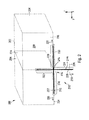
- Fig. 3 to 5 show a plurality of states when producing the component 212 from Fig. 2 by a stitching method. Furthermore, Fig. 3 to 5 show various components of a device 300 for carrying out the method.
- First and second fibres 212, 214 are deposited parallel to one another on a conveyor belt 302, moving in the conveying direction F, of the device 300, see Fig. 3 .
- a respective fibre 212, 214 is preferably configured as a "fibre tow" of individual fibres. The designations 2k to 24k are, for example, prevalent here.
- a respective fibre 212, 214 is preferably deposited dry, i.e. without a thermoplastic or thermosetting matrix, although a depositing of wet fibres 212, 214 is in no way ruled out.
- the device 300 furthermore comprises a reel 301 with continuous material 303, a cutting mechanism 305 and a depositing mechanism 304.
- the fibres 212, 214 are cut to length from the continuous material 303 by means of the cutting mechanism 305 and thereafter deposited on the conveyor belt 302 by means of the depositing mechanism 304, in particular a robot.
- the fibres 212, 214 preferably in each case have the same length and, after depositing, extend in the direction 306 transverse to the conveying direction F.
- the transverse direction 306 therefore corresponds to the longitudinal direction of the fibres 212, 214.
- the deposited fibres 212, 214 in each case have an offset 308 in the transverse direction 306 with respect to one another. This produces a first and second projection region 310, 312.
- the first projection region 310 only has ends of the first fibres 212 and the second projection region 312 only has ends of the second fibres 214.
- Fig. 4 shows how the ends of the first fibres 212 are stitched together in the projection region 310.
- a corresponding connecting mechanism of the device 300 comprises a needle 400 and a stitching fibre 402. The stitching takes place, for example, along a line 404.
- the ends of the second fibres 214 are stitched together in the second projection region 312.
- a corresponding connecting mechanism of the device 300 comprises a needle 406 and a stitching fibre 408. The stitching takes place, for example, along a line 410.
- the first and second fibres 212, 214 form an overlap region 412, in which they overlap in the transverse direction 306.
- the first and second fibres 212, 214 are stitched together in the overlap region 412, in particular along a centre line 414.
- the centre line 414 is arranged centrally in relation to a total extent 416 of the fibres 212, 214 in the transverse direction 306.
- a corresponding connecting mechanism in the form of a needle and a stitching fibre is designated by the reference numerals 418 and 420.
- the lines 404, 410, 414 are preferably parallel to one another.
- a respective upper stitching fibre 402, 408, 420 (“top thread") is preferably connected to a corresponding lower stitching fibre 421, 423, 425 (“bottom thread”).
- the conveyor belt 302 is preferably formed from a plurality of parts 422, 424, 426, 428, which form gaps 430, 432, 434 between them, through which a respective lower stitching thread 421, 423, 425 can easily be fed.
- the second fibres 214 are pivoted relative to the first fibres 212 about the centre line 414, i.e. about the stitching fibre 420, as indicated by the arrows in Fig. 5 .
- a respective first fibre 212 then preferably forms, with a respective second fibre 214, an angle 500 of 90 degrees.
- a component 210 is therefore formed, which thereafter is integrated in the crossing region 236 of the structural arrangement 200, see Fig. 2 , in particular as described above.
- the pivoting takes place, for example, by means of a pivoting mechanism of the device 300 in the form of a curved guide rail 501, which gradually rotates the second fibres 214 relative to the first fibres 212.
- the first fibres 212 may, for example, be moved onwards supported on horizontal guide rails 502 of the device 300, while the second fibres 214 pivot.
- the guide rails 500, 502 are only shown partially for the sake of greater clarity.
- the first and second fibres 212, 214 can be lifted from the conveyor belt 302, which is why this is not shown in Fig. 5 .
- first and second fibres 212, 214 can be woven or braided together by means of fibres 402, 408, 420.
- the first and second fibres 212, 214 can furthermore alternatively be glued to one another, in particular by means of a thermoplastic strand 600 (see Fig. 6 ), a fibre 702 sheathed with thermoplastic material 700 (see Fig. 7 ) or an adhesive strip 800 (see Fig. 8).
- Fig. 6 to 8 show a cross-sectional view, in each case.
- a first thermoplastic strand, a first sheathed fibre or a first adhesive strip extends along the first line 404 and connects the first fibres 212.
- a second thermoplastic strand, a second sheathed fibre or a second adhesive strip extends, for example, along the second line 410 and connects the second fibres 214.
- a third thermoplastic strand, a third sheathed fibre or a third adhesive strip extends, for example, along the centre line 414 and connects the first and second fibres 212, 214 to one another.
Applications Claiming Priority (2)
| Application Number | Priority Date | Filing Date | Title |
|---|---|---|---|
| DE102011084438A DE102011084438B3 (de) | 2011-10-13 | 2011-10-13 | Verfahren zum Herstellen einer Komponente zur Verbindung von Strukturen, Verfahren zum Herstellen einer Strukturanordnung sowie Vorrichtung zum Herstellen einer Komponente zur Verbindung von Strukturen |
| US201161552732P | 2011-10-28 | 2011-10-28 |
Publications (3)
| Publication Number | Publication Date |
|---|---|
| EP2581200A2 true EP2581200A2 (de) | 2013-04-17 |
| EP2581200A3 EP2581200A3 (de) | 2013-05-29 |
| EP2581200B1 EP2581200B1 (de) | 2016-07-27 |
Family
ID=47140637
Family Applications (1)
| Application Number | Title | Priority Date | Filing Date |
|---|---|---|---|
| EP12188065.2A Not-in-force EP2581200B1 (de) | 2011-10-13 | 2012-10-11 | Verfahren zur Herstellung einer Komponente zur Verbindung von Strukturen sowie Vorrichtung |
Country Status (3)
| Country | Link |
|---|---|
| US (1) | US9447530B2 (de) |
| EP (1) | EP2581200B1 (de) |
| DE (1) | DE102011084438B3 (de) |
Families Citing this family (5)
| Publication number | Priority date | Publication date | Assignee | Title |
|---|---|---|---|---|
| DE102011084441A1 (de) | 2011-10-13 | 2013-04-18 | Airbus Operations Gmbh | Verfahren zum Herstellen einer Komponente zur Verbindung von Strukturen, Komponente sowie Strukturanordnung |
| DE102011084433A1 (de) | 2011-10-13 | 2013-04-18 | Airbus Operations Gmbh | Komponente, Verstärkungsbauteil, Strukturanordnung, Luft- oder Raumfahrzeug sowie Verfahren |
| DE102011084472B3 (de) | 2011-10-13 | 2013-01-03 | Airbus Operations Gmbh | Strukturanordnung, Luft- oder Raumfahrzeug sowie Verfahren zum Herstellen einer Strukturanordnung |
| WO2017165178A1 (en) * | 2016-03-24 | 2017-09-28 | Honda Motor Co., Ltd. | Fabric processing method and component |
| FR3085126B1 (fr) * | 2018-08-27 | 2020-09-11 | Safran Nacelles | Procede de fabrication d'une preforme composite pour la fabrication d'un panneau composite a geometrie a double courbure |
Citations (2)
| Publication number | Priority date | Publication date | Assignee | Title |
|---|---|---|---|---|
| DE102007011613A1 (de) | 2007-01-22 | 2008-07-24 | Airbus Deutschland Gmbh | Beschlag zur Einleitung von hohen Kräften in eine Rumpfzelle eines Flugzeugs |
| US20100148008A1 (en) | 2008-12-17 | 2010-06-17 | Airbus Espana, S.L. | Rib-fitting |
Family Cites Families (40)
| Publication number | Priority date | Publication date | Assignee | Title |
|---|---|---|---|---|
| US661346A (en) | 1900-05-25 | 1900-11-06 | Marvin Lincoln | Spring-hinge. |
| US1843170A (en) | 1927-10-29 | 1932-02-02 | Charles R Meldrim | Wire hinge |
| US3818951A (en) | 1970-11-27 | 1974-06-25 | Secr Defence | Loom |
| USRE28672E (en) | 1971-07-06 | 1976-01-06 | Pliable tape structure | |
| US4122871A (en) * | 1976-07-07 | 1978-10-31 | Mcginley Thomas F | Method of weaving and apparatus therefor |
| DE2757965C3 (de) | 1977-12-24 | 1980-07-03 | Messerschmitt-Boelkow-Blohm Gmbh, 8000 Muenchen | Schubübertragungselement und Verfahren zu dessen Herstellung |
| DE3032443C2 (de) | 1980-08-28 | 1982-08-12 | Messerschmitt-Bölkow-Blohm GmbH, 8000 München | Bauelement mit einem Anschlußbereich mit versetzt angeordneten Bolzenaugen |
| US4622254A (en) | 1981-08-31 | 1986-11-11 | Toray Industries, Inc. | Fiber material for reinforcing plastics |
| US4395450A (en) | 1981-09-30 | 1983-07-26 | The Boeing Company | Composite structural skin spar joint and method of making |
| US4715560A (en) | 1983-03-14 | 1987-12-29 | Lear Fan Limited | Composite cruciform structure for joining intersecting structural members of an airframe and the like |
| WO1987001743A1 (en) | 1984-03-13 | 1987-03-26 | Shikishima Canvas Kabushiki Kaisha | Construction material reinforcing fiber structure |
| US4584226A (en) | 1984-04-30 | 1986-04-22 | Mcdonnell Douglas Corporation | Load transfer structure and method of making the same |
| JPS61179731A (ja) * | 1984-12-29 | 1986-08-12 | 日本マイヤー株式会社 | 三次元構造材料 |
| US4671470A (en) | 1985-07-15 | 1987-06-09 | Beech Aircraft Corporation | Method for fastening aircraft frame elements to sandwich skin panels covering same using woven fiber connectors |
| US5024874A (en) | 1989-02-16 | 1991-06-18 | Kabushiki Kaisha Toyoda Jidoshokki Seisakusho | Three dimensional fabric with a linkage structure |
| US5318422A (en) | 1992-11-05 | 1994-06-07 | Erland Robert K | Vacuum bag molding apparatus with channel and spline edge-seal |
| DE19527197A1 (de) | 1995-07-26 | 1997-01-30 | Henrik Schaefer | Werkstück aus Faserverbundmaterial |
| US5945053A (en) | 1998-03-13 | 1999-08-31 | Hettinga; Siebolt | Extruded-in fabric hinge and method of making same |
| EP1145841B8 (de) | 1998-10-12 | 2009-08-12 | Nitto Boseki Co., Ltd. | Verfahren zur herstellung einer multidirektionalen verstärkungsfaserbasis für verbundmaterialien |
| US6481911B1 (en) | 1999-11-24 | 2002-11-19 | Fritz Michael Streuber | Jointing method for joining preformed bodies |
| US6719870B2 (en) | 2000-12-15 | 2004-04-13 | The Boeing Company | Fastenerless internal support for hollow structures |
| US7521108B2 (en) | 2001-05-21 | 2009-04-21 | Lockheed Martin Corporation | Embedded connector attached to a base panel |
| DE10202440C1 (de) | 2002-01-22 | 2003-10-02 | Eads Deutschland Gmbh | Gelenk zur Verbindung einer Längsseite mit einer Oberseite von Bauteilen sowie flexibles Band zur Verwendung für ein derartiges Gelenk |
| DE10202439C1 (de) | 2002-01-22 | 2003-12-04 | Eads Deutschland Gmbh | Gelenk zur Verbindung von Bauteilen mit einander zugewandten Längsseiten sowie flexibles Band zur Verwendung für ein derartiges Gelenk |
| EP1595787B1 (de) | 2004-05-12 | 2017-12-06 | Subaru Corporation | Verfahren zur Herstellung einer Steuerfläche aus Verbundwerkstoff für ein Flugzeug |
| EP1627726A1 (de) | 2004-08-18 | 2006-02-22 | ABB Turbo Systems AG | Verbundfaserverdichter |
| EP1738895B1 (de) | 2005-06-29 | 2012-07-18 | SGL Carbon SE | Gelenk |
| US7943535B2 (en) | 2005-11-17 | 2011-05-17 | Albany Engineered Composites, Inc. | Hybrid three-dimensional woven/laminated struts for composite structural applications |
| DE102006035576B3 (de) * | 2006-07-27 | 2007-12-27 | Deutsches Zentrum für Luft- und Raumfahrt e.V. | Vorrichtung zur Herstellung einer Faserstruktur |
| DE102007012167B4 (de) | 2007-03-12 | 2013-05-29 | Eurocopter Deutschland Gmbh | Drillelastisches und biegesteifes Stabelement zum Lagern und Führen einer beweglichen Klappe gegenüber einem Flügel eines Luftfahrzeugs |
| DE102007012984B4 (de) | 2007-03-14 | 2018-10-11 | Airbus Helicopters Deutschland GmbH | Verbindungselement zur Kraftübertragung zwischen einem Klappenantrieb und einer an einem Flügel eines Luftfahrzeugs schwenkbeweglich gelagerten Klappe |
| DE102007019692B4 (de) | 2007-04-26 | 2011-06-01 | Airbus Operations Gmbh | Flügel-Rumpf-Sektion eines Flugzeugs |
| US7960298B2 (en) | 2007-12-07 | 2011-06-14 | Albany Engineered Composites, Inc. | Method for weaving closed structures with intersecting walls |
| FR2934613B1 (fr) | 2008-08-01 | 2010-10-15 | Airbus France | Assemblage d'elements fibreux pour l'obtention d'une piece en materiau composite. |
| DE102009024789A1 (de) | 2009-06-10 | 2010-12-16 | Daimler Ag | Verfahren zur Herstellung eines Formteils aus faserverstärktem Thermoplast |
| DE102009043103A1 (de) | 2009-09-26 | 2011-03-31 | Albert-Ludwigs-Universität Freiburg | Faserverbundstruktur |
| US8642151B2 (en) | 2011-01-21 | 2014-02-04 | Albany Engineered Composites, Inc. | Preform and method for reinforcing woven fiber nodes |
| DE102011084472B3 (de) | 2011-10-13 | 2013-01-03 | Airbus Operations Gmbh | Strukturanordnung, Luft- oder Raumfahrzeug sowie Verfahren zum Herstellen einer Strukturanordnung |
| DE102011084433A1 (de) | 2011-10-13 | 2013-04-18 | Airbus Operations Gmbh | Komponente, Verstärkungsbauteil, Strukturanordnung, Luft- oder Raumfahrzeug sowie Verfahren |
| DE102011084441A1 (de) | 2011-10-13 | 2013-04-18 | Airbus Operations Gmbh | Verfahren zum Herstellen einer Komponente zur Verbindung von Strukturen, Komponente sowie Strukturanordnung |
-
2011
- 2011-10-13 DE DE102011084438A patent/DE102011084438B3/de not_active Expired - Fee Related
-
2012
- 2012-10-11 US US13/649,226 patent/US9447530B2/en not_active Expired - Fee Related
- 2012-10-11 EP EP12188065.2A patent/EP2581200B1/de not_active Not-in-force
Patent Citations (2)
| Publication number | Priority date | Publication date | Assignee | Title |
|---|---|---|---|---|
| DE102007011613A1 (de) | 2007-01-22 | 2008-07-24 | Airbus Deutschland Gmbh | Beschlag zur Einleitung von hohen Kräften in eine Rumpfzelle eines Flugzeugs |
| US20100148008A1 (en) | 2008-12-17 | 2010-06-17 | Airbus Espana, S.L. | Rib-fitting |
Also Published As
| Publication number | Publication date |
|---|---|
| EP2581200B1 (de) | 2016-07-27 |
| US20130091675A1 (en) | 2013-04-18 |
| EP2581200A3 (de) | 2013-05-29 |
| US9447530B2 (en) | 2016-09-20 |
| DE102011084438B3 (de) | 2012-11-29 |
Similar Documents
| Publication | Publication Date | Title |
|---|---|---|
| US9447530B2 (en) | Method for producing a component for connecting structures and device | |
| US8967541B2 (en) | Structural arrangement, aircraft or spacecraft and method | |
| CN103209890B (zh) | 具有用于质量平衡的配重材料的复合旋翼桨叶 | |
| KR101261663B1 (ko) | 3차원으로 만곡된 섬유 복합재료 구조부품을 제조하기 위한방법 | |
| CN103303459B (zh) | 立体框架结构 | |
| EP2666622A1 (de) | Oberflächenhärterübergangszusammenstellung, Verfahren zur Herstellung und Anwendung besagter Oberflächenhärterübergangszusammenstellung | |
| ES2902069T3 (es) | Deflector para aeronave y método asociado | |
| CN103963956A (zh) | 用于承载负荷的箱式结构及其制造方法 | |
| EP2716544A1 (de) | Verkleidung für Flügelspitze | |
| CN102126550A (zh) | 飞行器座舱的活动部件和固定部件之间的易熔连接装置 | |
| US9623955B2 (en) | Composite reinforcement component, structural element, aircraft or spacecraft and method for producing a composite reinforcement component | |
| CN105936335A (zh) | 用于机翼和转子叶片结构的热塑性桁架结构和制造方法 | |
| CN106167085A (zh) | 用于飞机机身的耐压舱壁以及包括这种耐压舱壁的飞机 | |
| CN108372936A (zh) | 一种火箭轻质高效全动空气舵及其制造方法 | |
| EP3090940B1 (de) | Höhenleitwerk mit einem mehrfachrippentorsionskasten | |
| US20160297511A1 (en) | Rib structure and method of forming thereof | |
| US8833697B2 (en) | Component, reinforcement member, structural arrangement, aircraft or spacecraft and method | |
| EP2581303A2 (de) | Verfahren zur Herstellung einer Komponente zur Verbindung von Strukturen, Komponente und strukturelle Anordnung | |
| US9474339B2 (en) | Connecting device, assembly and method for manufacturing an assembly | |
| EP2767388A1 (de) | Faserverstärkte Kunststoffprofile mit Abschnitten mit unterschiedlichen Fasertypen | |
| US10046526B2 (en) | Method for producing a load introducing element | |
| US10399320B2 (en) | Assembling jig for mounting panel structure elements onto a surface of a CFRP panel | |
| RU77842U1 (ru) | Балка пола самолета из полимерных композиционных материалов | |
| CN104743097A (zh) | 飞行器的水平尾翼 | |
| US20140072769A1 (en) | Structural component |
Legal Events
| Date | Code | Title | Description |
|---|---|---|---|
| PUAI | Public reference made under article 153(3) epc to a published international application that has entered the european phase |
Free format text: ORIGINAL CODE: 0009012 |
|
| AK | Designated contracting states |
Kind code of ref document: A2 Designated state(s): AL AT BE BG CH CY CZ DE DK EE ES FI FR GB GR HR HU IE IS IT LI LT LU LV MC MK MT NL NO PL PT RO RS SE SI SK SM TR |
|
| AX | Request for extension of the european patent |
Extension state: BA ME |
|
| PUAL | Search report despatched |
Free format text: ORIGINAL CODE: 0009013 |
|
| AK | Designated contracting states |
Kind code of ref document: A3 Designated state(s): AL AT BE BG CH CY CZ DE DK EE ES FI FR GB GR HR HU IE IS IT LI LT LU LV MC MK MT NL NO PL PT RO RS SE SI SK SM TR |
|
| AX | Request for extension of the european patent |
Extension state: BA ME |
|
| RIC1 | Information provided on ipc code assigned before grant |
Ipc: B29C 70/14 20060101ALI20130419BHEP Ipc: B29C 70/76 20060101ALI20130419BHEP Ipc: B29C 70/20 20060101ALI20130419BHEP Ipc: B29C 70/22 20060101AFI20130419BHEP Ipc: B29C 70/24 20060101ALI20130419BHEP |
|
| 17P | Request for examination filed |
Effective date: 20130807 |
|
| RBV | Designated contracting states (corrected) |
Designated state(s): AL AT BE BG CH CY CZ DE DK EE ES FI FR GB GR HR HU IE IS IT LI LT LU LV MC MK MT NL NO PL PT RO RS SE SI SK SM TR |
|
| 17Q | First examination report despatched |
Effective date: 20150423 |
|
| GRAP | Despatch of communication of intention to grant a patent |
Free format text: ORIGINAL CODE: EPIDOSNIGR1 |
|
| INTG | Intention to grant announced |
Effective date: 20160324 |
|
| GRAS | Grant fee paid |
Free format text: ORIGINAL CODE: EPIDOSNIGR3 |
|
| GRAA | (expected) grant |
Free format text: ORIGINAL CODE: 0009210 |
|
| AK | Designated contracting states |
Kind code of ref document: B1 Designated state(s): AL AT BE BG CH CY CZ DE DK EE ES FI FR GB GR HR HU IE IS IT LI LT LU LV MC MK MT NL NO PL PT RO RS SE SI SK SM TR |
|
| REG | Reference to a national code |
Ref country code: GB Ref legal event code: FG4D |
|
| REG | Reference to a national code |
Ref country code: CH Ref legal event code: EP |
|
| REG | Reference to a national code |
Ref country code: AT Ref legal event code: REF Ref document number: 815427 Country of ref document: AT Kind code of ref document: T Effective date: 20160815 |
|
| REG | Reference to a national code |
Ref country code: IE Ref legal event code: FG4D |
|
| REG | Reference to a national code |
Ref country code: DE Ref legal event code: R096 Ref document number: 602012020940 Country of ref document: DE |
|
| REG | Reference to a national code |
Ref country code: FR Ref legal event code: PLFP Year of fee payment: 5 |
|
| REG | Reference to a national code |
Ref country code: LT Ref legal event code: MG4D |
|
| REG | Reference to a national code |
Ref country code: NL Ref legal event code: MP Effective date: 20160727 |
|
| REG | Reference to a national code |
Ref country code: AT Ref legal event code: MK05 Ref document number: 815427 Country of ref document: AT Kind code of ref document: T Effective date: 20160727 |
|
| PG25 | Lapsed in a contracting state [announced via postgrant information from national office to epo] |
Ref country code: HR Free format text: LAPSE BECAUSE OF FAILURE TO SUBMIT A TRANSLATION OF THE DESCRIPTION OR TO PAY THE FEE WITHIN THE PRESCRIBED TIME-LIMIT Effective date: 20160727 Ref country code: IT Free format text: LAPSE BECAUSE OF FAILURE TO SUBMIT A TRANSLATION OF THE DESCRIPTION OR TO PAY THE FEE WITHIN THE PRESCRIBED TIME-LIMIT Effective date: 20160727 Ref country code: LT Free format text: LAPSE BECAUSE OF FAILURE TO SUBMIT A TRANSLATION OF THE DESCRIPTION OR TO PAY THE FEE WITHIN THE PRESCRIBED TIME-LIMIT Effective date: 20160727 Ref country code: NO Free format text: LAPSE BECAUSE OF FAILURE TO SUBMIT A TRANSLATION OF THE DESCRIPTION OR TO PAY THE FEE WITHIN THE PRESCRIBED TIME-LIMIT Effective date: 20161027 Ref country code: NL Free format text: LAPSE BECAUSE OF FAILURE TO SUBMIT A TRANSLATION OF THE DESCRIPTION OR TO PAY THE FEE WITHIN THE PRESCRIBED TIME-LIMIT Effective date: 20160727 Ref country code: IS Free format text: LAPSE BECAUSE OF FAILURE TO SUBMIT A TRANSLATION OF THE DESCRIPTION OR TO PAY THE FEE WITHIN THE PRESCRIBED TIME-LIMIT Effective date: 20161127 Ref country code: RS Free format text: LAPSE BECAUSE OF FAILURE TO SUBMIT A TRANSLATION OF THE DESCRIPTION OR TO PAY THE FEE WITHIN THE PRESCRIBED TIME-LIMIT Effective date: 20160727 Ref country code: FI Free format text: LAPSE BECAUSE OF FAILURE TO SUBMIT A TRANSLATION OF THE DESCRIPTION OR TO PAY THE FEE WITHIN THE PRESCRIBED TIME-LIMIT Effective date: 20160727 |
|
| PGFP | Annual fee paid to national office [announced via postgrant information from national office to epo] |
Ref country code: GB Payment date: 20161020 Year of fee payment: 5 Ref country code: FR Payment date: 20161020 Year of fee payment: 5 Ref country code: DE Payment date: 20161020 Year of fee payment: 5 |
|
| PG25 | Lapsed in a contracting state [announced via postgrant information from national office to epo] |
Ref country code: AT Free format text: LAPSE BECAUSE OF FAILURE TO SUBMIT A TRANSLATION OF THE DESCRIPTION OR TO PAY THE FEE WITHIN THE PRESCRIBED TIME-LIMIT Effective date: 20160727 Ref country code: PT Free format text: LAPSE BECAUSE OF FAILURE TO SUBMIT A TRANSLATION OF THE DESCRIPTION OR TO PAY THE FEE WITHIN THE PRESCRIBED TIME-LIMIT Effective date: 20161128 Ref country code: BE Free format text: LAPSE BECAUSE OF NON-PAYMENT OF DUE FEES Effective date: 20160727 Ref country code: ES Free format text: LAPSE BECAUSE OF FAILURE TO SUBMIT A TRANSLATION OF THE DESCRIPTION OR TO PAY THE FEE WITHIN THE PRESCRIBED TIME-LIMIT Effective date: 20160727 Ref country code: SE Free format text: LAPSE BECAUSE OF FAILURE TO SUBMIT A TRANSLATION OF THE DESCRIPTION OR TO PAY THE FEE WITHIN THE PRESCRIBED TIME-LIMIT Effective date: 20160727 Ref country code: LV Free format text: LAPSE BECAUSE OF FAILURE TO SUBMIT A TRANSLATION OF THE DESCRIPTION OR TO PAY THE FEE WITHIN THE PRESCRIBED TIME-LIMIT Effective date: 20160727 Ref country code: GR Free format text: LAPSE BECAUSE OF FAILURE TO SUBMIT A TRANSLATION OF THE DESCRIPTION OR TO PAY THE FEE WITHIN THE PRESCRIBED TIME-LIMIT Effective date: 20161028 Ref country code: PL Free format text: LAPSE BECAUSE OF FAILURE TO SUBMIT A TRANSLATION OF THE DESCRIPTION OR TO PAY THE FEE WITHIN THE PRESCRIBED TIME-LIMIT Effective date: 20160727 |
|
| PG25 | Lapsed in a contracting state [announced via postgrant information from national office to epo] |
Ref country code: RO Free format text: LAPSE BECAUSE OF FAILURE TO SUBMIT A TRANSLATION OF THE DESCRIPTION OR TO PAY THE FEE WITHIN THE PRESCRIBED TIME-LIMIT Effective date: 20160727 Ref country code: EE Free format text: LAPSE BECAUSE OF FAILURE TO SUBMIT A TRANSLATION OF THE DESCRIPTION OR TO PAY THE FEE WITHIN THE PRESCRIBED TIME-LIMIT Effective date: 20160727 |
|
| REG | Reference to a national code |
Ref country code: DE Ref legal event code: R097 Ref document number: 602012020940 Country of ref document: DE |
|
| PG25 | Lapsed in a contracting state [announced via postgrant information from national office to epo] |
Ref country code: CZ Free format text: LAPSE BECAUSE OF FAILURE TO SUBMIT A TRANSLATION OF THE DESCRIPTION OR TO PAY THE FEE WITHIN THE PRESCRIBED TIME-LIMIT Effective date: 20160727 Ref country code: DK Free format text: LAPSE BECAUSE OF FAILURE TO SUBMIT A TRANSLATION OF THE DESCRIPTION OR TO PAY THE FEE WITHIN THE PRESCRIBED TIME-LIMIT Effective date: 20160727 Ref country code: SK Free format text: LAPSE BECAUSE OF FAILURE TO SUBMIT A TRANSLATION OF THE DESCRIPTION OR TO PAY THE FEE WITHIN THE PRESCRIBED TIME-LIMIT Effective date: 20160727 Ref country code: SM Free format text: LAPSE BECAUSE OF FAILURE TO SUBMIT A TRANSLATION OF THE DESCRIPTION OR TO PAY THE FEE WITHIN THE PRESCRIBED TIME-LIMIT Effective date: 20160727 Ref country code: BG Free format text: LAPSE BECAUSE OF FAILURE TO SUBMIT A TRANSLATION OF THE DESCRIPTION OR TO PAY THE FEE WITHIN THE PRESCRIBED TIME-LIMIT Effective date: 20161027 |
|
| REG | Reference to a national code |
Ref country code: CH Ref legal event code: PL |
|
| PLBE | No opposition filed within time limit |
Free format text: ORIGINAL CODE: 0009261 |
|
| STAA | Information on the status of an ep patent application or granted ep patent |
Free format text: STATUS: NO OPPOSITION FILED WITHIN TIME LIMIT |
|
| 26N | No opposition filed |
Effective date: 20170502 |
|
| REG | Reference to a national code |
Ref country code: IE Ref legal event code: MM4A |
|
| PG25 | Lapsed in a contracting state [announced via postgrant information from national office to epo] |
Ref country code: CH Free format text: LAPSE BECAUSE OF NON-PAYMENT OF DUE FEES Effective date: 20161031 Ref country code: LI Free format text: LAPSE BECAUSE OF NON-PAYMENT OF DUE FEES Effective date: 20161031 |
|
| PG25 | Lapsed in a contracting state [announced via postgrant information from national office to epo] |
Ref country code: LU Free format text: LAPSE BECAUSE OF NON-PAYMENT OF DUE FEES Effective date: 20161011 Ref country code: SI Free format text: LAPSE BECAUSE OF FAILURE TO SUBMIT A TRANSLATION OF THE DESCRIPTION OR TO PAY THE FEE WITHIN THE PRESCRIBED TIME-LIMIT Effective date: 20160727 |
|
| PG25 | Lapsed in a contracting state [announced via postgrant information from national office to epo] |
Ref country code: IE Free format text: LAPSE BECAUSE OF NON-PAYMENT OF DUE FEES Effective date: 20161011 |
|
| REG | Reference to a national code |
Ref country code: DE Ref legal event code: R119 Ref document number: 602012020940 Country of ref document: DE |
|
| PG25 | Lapsed in a contracting state [announced via postgrant information from national office to epo] |
Ref country code: HU Free format text: LAPSE BECAUSE OF FAILURE TO SUBMIT A TRANSLATION OF THE DESCRIPTION OR TO PAY THE FEE WITHIN THE PRESCRIBED TIME-LIMIT; INVALID AB INITIO Effective date: 20121011 Ref country code: CY Free format text: LAPSE BECAUSE OF FAILURE TO SUBMIT A TRANSLATION OF THE DESCRIPTION OR TO PAY THE FEE WITHIN THE PRESCRIBED TIME-LIMIT Effective date: 20160727 |
|
| GBPC | Gb: european patent ceased through non-payment of renewal fee |
Effective date: 20171011 |
|
| PG25 | Lapsed in a contracting state [announced via postgrant information from national office to epo] |
Ref country code: TR Free format text: LAPSE BECAUSE OF FAILURE TO SUBMIT A TRANSLATION OF THE DESCRIPTION OR TO PAY THE FEE WITHIN THE PRESCRIBED TIME-LIMIT Effective date: 20160727 Ref country code: MK Free format text: LAPSE BECAUSE OF FAILURE TO SUBMIT A TRANSLATION OF THE DESCRIPTION OR TO PAY THE FEE WITHIN THE PRESCRIBED TIME-LIMIT Effective date: 20160727 Ref country code: MT Free format text: LAPSE BECAUSE OF NON-PAYMENT OF DUE FEES Effective date: 20161031 Ref country code: MC Free format text: LAPSE BECAUSE OF FAILURE TO SUBMIT A TRANSLATION OF THE DESCRIPTION OR TO PAY THE FEE WITHIN THE PRESCRIBED TIME-LIMIT Effective date: 20160727 |
|
| REG | Reference to a national code |
Ref country code: FR Ref legal event code: ST Effective date: 20180629 |
|
| PG25 | Lapsed in a contracting state [announced via postgrant information from national office to epo] |
Ref country code: GB Free format text: LAPSE BECAUSE OF NON-PAYMENT OF DUE FEES Effective date: 20171011 Ref country code: DE Free format text: LAPSE BECAUSE OF NON-PAYMENT OF DUE FEES Effective date: 20180501 |
|
| PG25 | Lapsed in a contracting state [announced via postgrant information from national office to epo] |
Ref country code: FR Free format text: LAPSE BECAUSE OF NON-PAYMENT OF DUE FEES Effective date: 20171031 |
|
| PG25 | Lapsed in a contracting state [announced via postgrant information from national office to epo] |
Ref country code: AL Free format text: LAPSE BECAUSE OF FAILURE TO SUBMIT A TRANSLATION OF THE DESCRIPTION OR TO PAY THE FEE WITHIN THE PRESCRIBED TIME-LIMIT Effective date: 20160727 |