EP2581168A1 - Tragbare Maschine - Google Patents
Tragbare Maschine Download PDFInfo
- Publication number
- EP2581168A1 EP2581168A1 EP11184975.8A EP11184975A EP2581168A1 EP 2581168 A1 EP2581168 A1 EP 2581168A1 EP 11184975 A EP11184975 A EP 11184975A EP 2581168 A1 EP2581168 A1 EP 2581168A1
- Authority
- EP
- European Patent Office
- Prior art keywords
- machine
- machine according
- handheld
- handheld machine
- user
- Prior art date
- Legal status (The legal status is an assumption and is not a legal conclusion. Google has not performed a legal analysis and makes no representation as to the accuracy of the status listed.)
- Withdrawn
Links
Images

Classifications
-
- B—PERFORMING OPERATIONS; TRANSPORTING
- B24—GRINDING; POLISHING
- B24B—MACHINES, DEVICES, OR PROCESSES FOR GRINDING OR POLISHING; DRESSING OR CONDITIONING OF ABRADING SURFACES; FEEDING OF GRINDING, POLISHING, OR LAPPING AGENTS
- B24B55/00—Safety devices for grinding or polishing machines; Accessories fitted to grinding or polishing machines for keeping tools or parts of the machine in good working condition
-
- B—PERFORMING OPERATIONS; TRANSPORTING
- B25—HAND TOOLS; PORTABLE POWER-DRIVEN TOOLS; MANIPULATORS
- B25F—COMBINATION OR MULTI-PURPOSE TOOLS NOT OTHERWISE PROVIDED FOR; DETAILS OR COMPONENTS OF PORTABLE POWER-DRIVEN TOOLS NOT PARTICULARLY RELATED TO THE OPERATIONS PERFORMED AND NOT OTHERWISE PROVIDED FOR
- B25F5/00—Details or components of portable power-driven tools not particularly related to the operations performed and not otherwise provided for
- B25F5/006—Vibration damping means
-
- B—PERFORMING OPERATIONS; TRANSPORTING
- B25—HAND TOOLS; PORTABLE POWER-DRIVEN TOOLS; MANIPULATORS
- B25F—COMBINATION OR MULTI-PURPOSE TOOLS NOT OTHERWISE PROVIDED FOR; DETAILS OR COMPONENTS OF PORTABLE POWER-DRIVEN TOOLS NOT PARTICULARLY RELATED TO THE OPERATIONS PERFORMED AND NOT OTHERWISE PROVIDED FOR
- B25F5/00—Details or components of portable power-driven tools not particularly related to the operations performed and not otherwise provided for
- B25F5/02—Construction of casings, bodies or handles
-
- B—PERFORMING OPERATIONS; TRANSPORTING
- B23—MACHINE TOOLS; METAL-WORKING NOT OTHERWISE PROVIDED FOR
- B23B—TURNING; BORING
- B23B2270/00—Details of turning, boring or drilling machines, processes or tools not otherwise provided for
- B23B2270/48—Measuring or detecting
Definitions
- the invention relates to a handheld machine, such as a sander, a polisher, an angle grinder or a drilling machine for instance.
- Nailing machines, and other corresponding hand-held machines that cause impulses to the user's hand, are easily understandable to be a potential health risk for the user.
- An object of the invention is to alleviate the above disadvantages. This is achieved with the invention defined in the independent claim. Some embodiments are disclosed in the dependent claims.
- the following embodiments relate to powered handheld machines/tools, such as grinding, sanding or polishing machines.
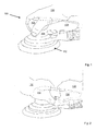
- Figures 1 and 2 show examples of use of a sander with one hand ( Figure 1 , 130) and two hands ( Figure 2 , 130, 132).
- the exemplary sander has, as a tool, a rotary and/or oscillating circular sanding disk 102, to which abrasive material can be attached.
- the rotary and/or oscillating motion of the tool is provided by a motor arranged in the motor housing 104.
- the tool can alternatively have other forms, such as triangular, square or rectangular.
- a grip 106 which is specially adapted to be gripped with one hand.
- the grip may be round and sized such that when the palm of the hand rests against the top surface of the grip, the fingers set around the grip 106.
- the grip 106 is positioned substantially above the tool 102.
- the grip is centrally positioned with respect to the tool. That is, the middle axis of the round grip coincides with the middle axis of the disc and the motor. In this way, the device is optimized for one-hand use, because a pressing force exerted by the user on the grip delivers the same pressing force on the tool 102 via the rigid motor housing 104.
- the mutual positioning of the grip 106 and the disk 102 may be slightly eccentric.
- the exemplary sanding machine of Figures 1 and 2 also contains a second grip 108 for providing support for a second hand of a user.
- the second grip may be an elongated grip, and formed such that the user may set the palm of the hand against the top surface of the grip 108. The thumb of the hand then sets on one side of the grip 108, and the other fingers on the other side of the grip.
- Figure 3 shows an embodiment of a sander, in which the second handle portion 108 is shown without the outer covering such that the inner structure is visible.
- PCB printed circuit board
- the PCB 110 is populated with electrical components and includes also the processor of the machine.
- the PCB 110 is shaped such that it fits within the elongated second grip 108.
- the PCB may be encapsulated with plastic such as to improve the shock-resistance of the board.
- the acceleration sensor may be a three-dimension (3D) sensor but may alternatively be a 1 D or a 2D sensor.
- the sensor may also be capable of measuring horizontal and/or vertical rotation acceleration.
- Figure 3 shows an embodiment of the positioning of the acceleration sensor.
- the acceleration sensor 112 is positioned at the end of the PCB 110 close to the first grip 106.
- the acceleration sensor lies just under the palm of the first hand 130 of the user.
- the acceleration sensor's position is optimally between the two hands.
- the sensor is capable of optimally providing working safety to a user in both operation modes.
- an additional sensor could be placed to the other end of the PCB than the sensor 112. Or, at least, optimally, there should be at least a couple (2 cm) of centimeter's distance between the sensors.
- the sensors are placed substantially onto the middle axis, that is, the symmetry axis, of the handgrip/machine, whereby the vibration data provided by them is directly comparable.
- the data provided by the two or more sensors may be treated separately, or combined to give an overview of the dynamics of the overall vibration of the machine.
- a communication module 114 which can be a Bluetooth communication module, for instance. Other known forms of communication can as well be applied.
- Figure 4 shows one embodiment of the structure of the PCB. On the left, there are wire terminals 116 for connecting the PCB to the motor of the device. The other end of the PCB provides an electrical connector 124 for connecting the device to a power input.
- the acceleration sensor 112 is positioned in the close proximity of the wire terminals 116 of the PCB.
- the processor/controller 120 is positioned substantially in the middle of the PCB.
- the processor may include a memory section storing software code for running the operations of the processor.
- the PCB may also comprise a separate memory module.
- Data, such as data collected by the acceleration sensor may be stored on the memory of the processor and/or the separate memory module.
- the acceleration sensor may comprise a memory for storing data measured by it.
- the communication module 114 may be positioned as close as possible to the processor.
- Figure 4 also shows a transistor driver 118 and buttons 122 of the PCB.
- the acceleration sensor may provide a momentary acceleration value, which may be evaluated per acceleration direction. For instance, in a 3D acceleration sensor, the x-, y-, and z-directions are evaluated separately. The respective individual acceleration values may be compared to a respective threshold value, and a warning may be given if the threshold value is exceeded.
- the threshold values of the different acceleration directions may be the same, or may differ from each other. For instance, more acceleration may be tolerated in x-, and y-directions than the z-direction.
- a sum vector is formed from the different axial acceleration values.
- the length of the sum vector and/or the direction of the vector may be taken into account when comparing the vector to its threshold settings to determine whether the momentary vibration level complies with a secure vibration level.
- the calculation of the sum vector may be carried out in the acceleration sensor, or in the processor operatively coupled to the acceleration sensor.
- cumulative vibration dosage over a working session may be estimated.
- the cumulative dosage may be estimated either real-time, or after the working session. If the dosage is estimated real-time, a warning may be given to the user if/when the dosage reaches a threshold setting of the cumulative dosage.
- the vibration data during a working session may be stored to a memory of the sensor, the processor, the PCB or an external device.
- the memory may be capable of storing data from the previous 12 hours, for instance.
- the stored data may comprise, for instance, one or more of the following: a time stamp for each data record, an acceleration data of a linear acceleration value, a sum vector of two or more linear acceleration sensors and/or one or more rotation acceleration sensors, a cumulative vibration value, a rotating speed of the tool and an identifier of a user using the machine.
- the communication unit may send data measured and/or stored in the device to outside of the machine.
- the communication unit may apply Bluetooth, radio frequency transmission, wired transmission, or some other known transmission method when transmitting the data.
- Vibration data may be sent online during the working session, or after the working session has been completed. The data may be sent to an external computer connected to the machine.
- the communication unit may also be capable of receiving data from an external device. Same communication methods may be applied in receiving data as when transmitting it.
- the received data may include, for instance, an instruction to take a sensor to use, a threshold setting for a linear acceleration sensor, a threshold setting for a rotation sensor, a threshold setting for a vector formed by summing measurement values of one or more linear acceleration sensors and/or rotation sensors and user identification.
- the thresholds are set based on who is using the machine.
- the device may be provided with a plurality of acceleration sensors that are provided on the PCB.
- the sensors are provided on the PCB already at the manufacturing phase of the machine, the number of sensor and their positioning can be optimally planned.
- the sensors may be provided with a plurality of the capabilities.
- each sensor may comprise x-, y-, z-, and rotation sensors. Initially, at least some of the sensors may not even be set to be operating. The user may then be provided with a possibility to upload to the machine an instruction to activate those sensors that he/she wishes. The user may also be provided with a possibility to activate only a subset of features provided in each sensor. For instance, the user may wish to activate only x-sensors on each sensor and keep y- and z-sensors deactivated.
- This solution allows the user to effectively interact with the machine and modify its operation such that it best fits the individual's needs.
- the cooperation of the acceleration sensors and the communication link providing a bidirectional communication allow the user to modify the hand-held tool where the acceleration sensors are integrally formed part of the machine's inner structure and are not readily accessible.
- the machine may comprise an indicating unit for indicating various vibration values and/or giving warnings during the working session when needed. Indications may be given to the user via a display on the body of the machine, and/or by giving a sound warning.
- the visual display might be positioned to the area that is between the hands 130, 132.
- the visual display may use colors, for instance, to indicate acceptable or non-acceptable working levels. If the working level is acceptable, that is, the momentary and/or cumulative dosages are below the respective threshold levels, the display may use green color. Yellow may indicate that the working level is near to an unacceptable level, and red may indicate that a threshold setting has been exceeded. In an embodiment, the machine may even stop and prevent working if the daily cumulative dosage has been exceeded.
- the collection and analysis of data may have the important task of improving working safety. Continuously too high momentary or cumulative threshold values may indicate, for instance, that the user is depressing the machine against the working surface too much. Other indications may also be derived, such as whether the tool applied in the working machine may be too coarse, or whether that the rotating speed applied in the work is appropriate. Data may also indicate that, at certain rotating speed values of the tool, one or more vibration values rapidly increase. This phenomenon may be due to a resonance between the two. Based on this analysis, the user may be guided to avoid certain rotating speeds, or the machine may even be instructed to do so. Analysis of the collected data may also be useful in evaluation the condition of the machine.
- Exceptionally high vibration values may also be an indication of that the machine is broken or that the tool is broken or mounted in a wrong way.
- Analysis of the collected data may be also performed by a supervisor of the user. Based on the collected data, the supervisor can also see the start and end moments of the work session, and the breaks held by user.
- the computer may be applied in vibration data analysis collected from the machine and/or provision of input data to be fed to the machine.
- the data analysis may be carried out by using visual graphs presented for a user, or to his/her supervisor and a software package may be provided on the computer to perform the analysis.
- Positioning of the acceleration sensor directly on the PCB is a simple solution and provides advantages in mass production. That is, when the machine after all includes a PCB, it is advantageous to utilize the available space therein for accommodating also the acceleration sensor. There is thus no need to seek a position/room for the sensor elsewhere within the housing of the device.
- the communication between the sensor and the processor can be arranged optimally. If the sensor is arranged somewhere else in the housing of the device, the wiring between the sensor and the processor affects the whole design of the device.
- the acceleration sensor when the acceleration sensor is encapsulated into the housing of the machine, the sensor is well protected from external shocks.
- acceleration sensor when the acceleration sensor is provided on the machine's PCB, no extra power feeding for the acceleration sensor is needed. Battery-operated acceleration sensors have the risk of running out of power, thereby endangering the safety of the user.
- Collection and utilization of vibration data is especially advantageous in oscillating sanders, which are often used during long and continuous working sessions.
- the dangers associated with working with a sander are thereby more associated with the length of the working session and the cumulative vibration dosage thereof in contrast to some other machines where the dangers associated to the working are immediately apparent due to high momentary impulses, for instance.
- Collection of the vibration data may easily also reveal incorrect assembly of a work tool. A warning of exceptionally high vibration values may be given such that the user may correct the assembly.
- the collected vibration data may also be applied to balance the machine.
- the machine may comprise physical positions where the user may add weights to, or remove weights from.
- the vibration data may directly indicate to the user how he should balance the machine by using the weights.
- the machine may comprise electrically controllable balancing units.
- the processor may then automatically balance the machine during operation based on the vibration data collected from the sensor(s).
- division of functionality between the acceleration sensor(s), processor, the communication module, and an external computer can be distributed/divided in various ways.
- a memory for storing the vibration data may be arranged in any of these modules.
- the calculation of a cumulative vibration value may be performed in any of the acceleration sensor, the processor or the externally connected computer.
- data may be directly conveyed from the acceleration sensor to the communication module, or data may be first conveyed to the processor, and therefrom to the communication unit.
- the first and/or second electronic device may comprise a processor, which can be a general-purpose processor configured to execute a computer program tangibly recorded on a non-transitory computer-readable recording medium, such as a ROM, hard disk drive, optical memory or flash memory.
- the general-purpose processor can be configured to carry out the operative functions described herein by executing the computer program recorded on the non-transitory computer-readable recording medium.
- the processor can be an application-specific processor that is specifically configured to carry out the operative functions described herein.
- the non-transitory computer-readable recording medium can be memory-resident and/or communicatively connected to the respective electronic device.
Priority Applications (1)
| Application Number | Priority Date | Filing Date | Title |
|---|---|---|---|
| EP11184975.8A EP2581168A1 (de) | 2011-10-13 | 2011-10-13 | Tragbare Maschine |
Applications Claiming Priority (1)
| Application Number | Priority Date | Filing Date | Title |
|---|---|---|---|
| EP11184975.8A EP2581168A1 (de) | 2011-10-13 | 2011-10-13 | Tragbare Maschine |
Publications (1)
| Publication Number | Publication Date |
|---|---|
| EP2581168A1 true EP2581168A1 (de) | 2013-04-17 |
Family
ID=44799786
Family Applications (1)
| Application Number | Title | Priority Date | Filing Date |
|---|---|---|---|
| EP11184975.8A Withdrawn EP2581168A1 (de) | 2011-10-13 | 2011-10-13 | Tragbare Maschine |
Country Status (1)
| Country | Link |
|---|---|
| EP (1) | EP2581168A1 (de) |
Cited By (10)
| Publication number | Priority date | Publication date | Assignee | Title |
|---|---|---|---|---|
| DE102013211997A1 (de) * | 2013-06-25 | 2015-01-08 | Robert Bosch Gmbh | Handwerkzeugmaschine mit einer Sensorvorrichtung |
| WO2016174971A1 (ja) * | 2015-04-27 | 2016-11-03 | 日立工機株式会社 | 電動工具 |
| WO2016206860A1 (de) * | 2015-06-24 | 2016-12-29 | Robert Bosch Gmbh | Handwerkzeugmaschine, insbesondere elektrohandwerkzeugmaschine |
| WO2017084614A1 (en) | 2015-11-20 | 2017-05-26 | Tti (Macao Commercial Offshore) Limited | Power tools with integrated circuit boards |
| CN109070327A (zh) * | 2016-05-06 | 2018-12-21 | 鲁卡斯液压有限公司 | 用于运行工作器具或救生器具的方法、工作器具或救生器具以及能量源 |
| US10437240B2 (en) | 2016-09-13 | 2019-10-08 | Toyota Motor Engineering & Manufacturing North America, Inc. | Manufacturing evaluation system |
| US10510199B2 (en) | 2017-08-07 | 2019-12-17 | Milwaukee Electric Tool Corporation | Power tool with irreversably lockable compartment |
| US11212909B2 (en) | 2019-11-21 | 2021-12-28 | Milwaukee Electric Tool Corporation | Insertable wireless communication device for a power tool |
| US11260514B2 (en) | 2017-11-29 | 2022-03-01 | Milwaukee Electric Tool Corporation | Externally attachable tracking module for a power tool |
| US11665519B2 (en) | 2019-02-06 | 2023-05-30 | Milwaukee Electric Tool Corporation | Power tool with shared terminal block |
Citations (4)
| Publication number | Priority date | Publication date | Assignee | Title |
|---|---|---|---|---|
| EP1008422A2 (de) * | 1998-12-10 | 2000-06-14 | HILTI Aktiengesellschaft | Verfahren und Einrichtung zur Vermeidung von Unfällen bei handgeführten Werkzeugmaschinen durch Werkzeugblockieren |
| DE102004046000A1 (de) * | 2004-09-17 | 2006-03-23 | C. & E. Fein Gmbh | Elektrowerkzeug |
| US7036703B2 (en) * | 2003-01-27 | 2006-05-02 | Hilti Aktiengesellschaft | Hand-held working tool |
| JP2011020230A (ja) * | 2009-07-17 | 2011-02-03 | Hitachi Koki Co Ltd | 携帯用工具 |
-
2011
- 2011-10-13 EP EP11184975.8A patent/EP2581168A1/de not_active Withdrawn
Patent Citations (4)
| Publication number | Priority date | Publication date | Assignee | Title |
|---|---|---|---|---|
| EP1008422A2 (de) * | 1998-12-10 | 2000-06-14 | HILTI Aktiengesellschaft | Verfahren und Einrichtung zur Vermeidung von Unfällen bei handgeführten Werkzeugmaschinen durch Werkzeugblockieren |
| US7036703B2 (en) * | 2003-01-27 | 2006-05-02 | Hilti Aktiengesellschaft | Hand-held working tool |
| DE102004046000A1 (de) * | 2004-09-17 | 2006-03-23 | C. & E. Fein Gmbh | Elektrowerkzeug |
| JP2011020230A (ja) * | 2009-07-17 | 2011-02-03 | Hitachi Koki Co Ltd | 携帯用工具 |
Cited By (21)
| Publication number | Priority date | Publication date | Assignee | Title |
|---|---|---|---|---|
| DE102013211997A1 (de) * | 2013-06-25 | 2015-01-08 | Robert Bosch Gmbh | Handwerkzeugmaschine mit einer Sensorvorrichtung |
| WO2016174971A1 (ja) * | 2015-04-27 | 2016-11-03 | 日立工機株式会社 | 電動工具 |
| JPWO2016174971A1 (ja) * | 2015-04-27 | 2018-01-18 | 日立工機株式会社 | 電動工具 |
| WO2016206860A1 (de) * | 2015-06-24 | 2016-12-29 | Robert Bosch Gmbh | Handwerkzeugmaschine, insbesondere elektrohandwerkzeugmaschine |
| US10723010B2 (en) | 2015-06-24 | 2020-07-28 | Robert Bosch Gmbh | Hand-held power tool, in particular electric hand tool |
| US11110583B2 (en) | 2015-11-20 | 2021-09-07 | Tti (Macao Commercial Offshore) Limited | Power tools with integrated circuit boards |
| WO2017084614A1 (en) | 2015-11-20 | 2017-05-26 | Tti (Macao Commercial Offshore) Limited | Power tools with integrated circuit boards |
| EP3377272A4 (de) * | 2015-11-20 | 2019-07-24 | TTI (Macao Commercial Offshore) Limited | Elektrowerkzeuge mit leiterplatten |
| CN109070327A (zh) * | 2016-05-06 | 2018-12-21 | 鲁卡斯液压有限公司 | 用于运行工作器具或救生器具的方法、工作器具或救生器具以及能量源 |
| CN109070327B (zh) * | 2016-05-06 | 2022-02-25 | 鲁卡斯液压有限公司 | 用于运行救援器具的方法、救援器具以及能量源 |
| US10437240B2 (en) | 2016-09-13 | 2019-10-08 | Toyota Motor Engineering & Manufacturing North America, Inc. | Manufacturing evaluation system |
| US10950074B2 (en) | 2017-08-07 | 2021-03-16 | Milwaukee Electric Tool Corporation | Power tool with irreversably lockable compartment |
| US10510199B2 (en) | 2017-08-07 | 2019-12-17 | Milwaukee Electric Tool Corporation | Power tool with irreversably lockable compartment |
| US11869288B2 (en) | 2017-08-07 | 2024-01-09 | Milwaukee Electric Tool Corporation | Power tool with compartment for receiving another device |
| US11260514B2 (en) | 2017-11-29 | 2022-03-01 | Milwaukee Electric Tool Corporation | Externally attachable tracking module for a power tool |
| US11665519B2 (en) | 2019-02-06 | 2023-05-30 | Milwaukee Electric Tool Corporation | Power tool with shared terminal block |
| US11963079B2 (en) | 2019-02-06 | 2024-04-16 | Milwaukee Electric Tool Corporation | Power tool with shared terminal block |
| US11212909B2 (en) | 2019-11-21 | 2021-12-28 | Milwaukee Electric Tool Corporation | Insertable wireless communication device for a power tool |
| US11375610B2 (en) | 2019-11-21 | 2022-06-28 | Milwaukee Electric Tool Corporation | Insertable wireless communication device for a power tool |
| US11570888B2 (en) | 2019-11-21 | 2023-01-31 | Milwaukee Electric Tool Corporation | Insertable wireless communication device for a power tool |
| US11871509B2 (en) | 2019-11-21 | 2024-01-09 | Milwaukee Electric Tool Corporation | Insertable wireless communication device for a power tool |
Similar Documents
| Publication | Publication Date | Title |
|---|---|---|
| EP2581168A1 (de) | Tragbare Maschine | |
| EP1586875A1 (de) | Vibrationsdosimeter | |
| US10046429B2 (en) | System having at least one power tool and having at least one mobile sensor device | |
| JP6574892B2 (ja) | 制御装置及び制御プログラム | |
| US9126072B2 (en) | Free weight monitoring system | |
| US20200276680A1 (en) | High-precision kickback detection for power tools | |
| KR101864257B1 (ko) | 칫솔질 모니터링 장치 | |
| US20160279782A1 (en) | Power Tool, in Particular Portable Power Tool, Having a Motorized Drive Unit and Having At Least One Sensor Device | |
| US9501084B1 (en) | Wearable electronic device with force feedback | |
| EP2083252A1 (de) | Dosimeter für Schwingungen | |
| JP2017532461A (ja) | 1つ以上の衝撃センサを有する装着可能な装置 | |
| CN205588250U (zh) | 振荡式工具机 | |
| KR20150006787A (ko) | 전동칫솔 칫솔모에 가해지는 압력 측정 장치 및 방법 | |
| CN110039495A (zh) | 电动工具中的操作数据分布 | |
| CN112654463B (zh) | 电动工具及处理装置 | |
| US10005164B2 (en) | Method for operating at least one hand-held power tool | |
| EP3781915B1 (de) | Vorrichtung zur messung einer schwingungsdosis | |
| RU2473057C2 (ru) | Вибродозиметр для определения вибрационной нагрузки | |
| CN111182822A (zh) | 抽吸器具 | |
| US20210283761A1 (en) | Method for Enabling an Active Operating State of a Hand-Held Power Tool According to Whether an Item of Protective Equipment is Carried or Worn by an Operator of the Hand-Held Power Tool | |
| WO2016117536A1 (ja) | 加工装置及びカートリッジ | |
| US20230170902A1 (en) | Hand-held machine tool and related method | |
| CN101920111B (zh) | 手持式操作控制装置及游戏机 | |
| CN207301976U (zh) | 一种数据手套及vr系统 | |
| CN107520818A (zh) | 用于辅助便携式工具机的操作者的方法 |
Legal Events
| Date | Code | Title | Description |
|---|---|---|---|
| PUAI | Public reference made under article 153(3) epc to a published international application that has entered the european phase |
Free format text: ORIGINAL CODE: 0009012 |
|
| AK | Designated contracting states |
Kind code of ref document: A1 Designated state(s): AL AT BE BG CH CY CZ DE DK EE ES FI FR GB GR HR HU IE IS IT LI LT LU LV MC MK MT NL NO PL PT RO RS SE SI SK SM TR |
|
| AX | Request for extension of the european patent |
Extension state: BA ME |
|
| STAA | Information on the status of an ep patent application or granted ep patent |
Free format text: STATUS: THE APPLICATION IS DEEMED TO BE WITHDRAWN |
|
| 18D | Application deemed to be withdrawn |
Effective date: 20131018 |