EP2581024A2 - Schlauchleitung mit überdeckenden Zungen, insbesondere für einen Staubsauger - Google Patents
Schlauchleitung mit überdeckenden Zungen, insbesondere für einen Staubsauger Download PDFInfo
- Publication number
- EP2581024A2 EP2581024A2 EP12187822.7A EP12187822A EP2581024A2 EP 2581024 A2 EP2581024 A2 EP 2581024A2 EP 12187822 A EP12187822 A EP 12187822A EP 2581024 A2 EP2581024 A2 EP 2581024A2
- Authority
- EP
- European Patent Office
- Prior art keywords
- hose
- tongues
- hose line
- suction
- line according
- Prior art date
- Legal status (The legal status is an assumption and is not a legal conclusion. Google has not performed a legal analysis and makes no representation as to the accuracy of the status listed.)
- Granted
Links
- 210000002105 tongue Anatomy 0.000 title claims abstract description 70
- 230000004888 barrier function Effects 0.000 claims abstract description 10
- 238000009499 grossing Methods 0.000 claims abstract description 6
- 239000000428 dust Substances 0.000 description 16
- 239000004033 plastic Substances 0.000 description 8
- 229920003023 plastic Polymers 0.000 description 8
- 238000013461 design Methods 0.000 description 7
- 238000004519 manufacturing process Methods 0.000 description 7
- 238000005452 bending Methods 0.000 description 6
- 238000004026 adhesive bonding Methods 0.000 description 4
- 239000000356 contaminant Substances 0.000 description 4
- 238000001125 extrusion Methods 0.000 description 4
- 239000012530 fluid Substances 0.000 description 4
- 238000012549 training Methods 0.000 description 4
- 239000004743 Polypropylene Substances 0.000 description 3
- 230000008021 deposition Effects 0.000 description 3
- 230000000694 effects Effects 0.000 description 3
- 229920001155 polypropylene Polymers 0.000 description 3
- 238000011144 upstream manufacturing Methods 0.000 description 3
- 238000003466 welding Methods 0.000 description 3
- 239000004831 Hot glue Substances 0.000 description 2
- 239000004952 Polyamide Substances 0.000 description 2
- 238000010521 absorption reaction Methods 0.000 description 2
- 238000004140 cleaning Methods 0.000 description 2
- 238000011161 development Methods 0.000 description 2
- 230000018109 developmental process Effects 0.000 description 2
- 238000005516 engineering process Methods 0.000 description 2
- 239000003000 extruded plastic Substances 0.000 description 2
- 230000001771 impaired effect Effects 0.000 description 2
- 229920002647 polyamide Polymers 0.000 description 2
- 230000002035 prolonged effect Effects 0.000 description 2
- 239000000243 solution Substances 0.000 description 2
- 238000004804 winding Methods 0.000 description 2
- 239000003086 colorant Substances 0.000 description 1
- 238000004891 communication Methods 0.000 description 1
- 230000000295 complement effect Effects 0.000 description 1
- 238000001816 cooling Methods 0.000 description 1
- 230000006735 deficit Effects 0.000 description 1
- 230000001419 dependent effect Effects 0.000 description 1
- 230000005489 elastic deformation Effects 0.000 description 1
- 230000002349 favourable effect Effects 0.000 description 1
- 238000002347 injection Methods 0.000 description 1
- 239000007924 injection Substances 0.000 description 1
- 238000001746 injection moulding Methods 0.000 description 1
- 238000009434 installation Methods 0.000 description 1
- 230000000670 limiting effect Effects 0.000 description 1
- 239000007788 liquid Substances 0.000 description 1
- 238000000034 method Methods 0.000 description 1
- 239000002991 molded plastic Substances 0.000 description 1
- 239000002245 particle Substances 0.000 description 1
- 229920000098 polyolefin Polymers 0.000 description 1
- -1 polypropylene Polymers 0.000 description 1
- 238000003860 storage Methods 0.000 description 1
- 238000012546 transfer Methods 0.000 description 1
- 230000000007 visual effect Effects 0.000 description 1
Images


Classifications
-
- A—HUMAN NECESSITIES
- A47—FURNITURE; DOMESTIC ARTICLES OR APPLIANCES; COFFEE MILLS; SPICE MILLS; SUCTION CLEANERS IN GENERAL
- A47L—DOMESTIC WASHING OR CLEANING; SUCTION CLEANERS IN GENERAL
- A47L9/00—Details or accessories of suction cleaners, e.g. mechanical means for controlling the suction or for effecting pulsating action; Storing devices specially adapted to suction cleaners or parts thereof; Carrying-vehicles specially adapted for suction cleaners
- A47L9/24—Hoses or pipes; Hose or pipe couplings
- A47L9/248—Parts, details or accessories of hoses or pipes
-
- A—HUMAN NECESSITIES
- A47—FURNITURE; DOMESTIC ARTICLES OR APPLIANCES; COFFEE MILLS; SPICE MILLS; SUCTION CLEANERS IN GENERAL
- A47L—DOMESTIC WASHING OR CLEANING; SUCTION CLEANERS IN GENERAL
- A47L9/00—Details or accessories of suction cleaners, e.g. mechanical means for controlling the suction or for effecting pulsating action; Storing devices specially adapted to suction cleaners or parts thereof; Carrying-vehicles specially adapted for suction cleaners
- A47L9/24—Hoses or pipes; Hose or pipe couplings
-
- F—MECHANICAL ENGINEERING; LIGHTING; HEATING; WEAPONS; BLASTING
- F16—ENGINEERING ELEMENTS AND UNITS; GENERAL MEASURES FOR PRODUCING AND MAINTAINING EFFECTIVE FUNCTIONING OF MACHINES OR INSTALLATIONS; THERMAL INSULATION IN GENERAL
- F16L—PIPES; JOINTS OR FITTINGS FOR PIPES; SUPPORTS FOR PIPES, CABLES OR PROTECTIVE TUBING; MEANS FOR THERMAL INSULATION IN GENERAL
- F16L11/00—Hoses, i.e. flexible pipes
- F16L11/14—Hoses, i.e. flexible pipes made of rigid material, e.g. metal or hard plastics
- F16L11/16—Hoses, i.e. flexible pipes made of rigid material, e.g. metal or hard plastics wound from profiled strips or bands
Definitions
- the invention relates to a hose with a longitudinally corrugated, inner troughs having wall, in particular for use as a suction hose to a vacuum cleaner, wherein in the region of the inner troughs for pneumatic and / or hydraulic smoothing of the hose a barrier in the form of opposite to each other in the direction of Wellental projecting and the trough overlapping tongues is provided, and equipped with such a hose vacuum cleaner.
- Vacuum cleaners serve to absorb dirt from floor surfaces, furniture or the like by a suction air flow.
- the suction mouth of a suction nozzle is placed on the surface to be cleaned, so that dust or other contaminants are sucked in by the suction air flow.
- the suction air flow is generated by a suction fan, which is in flow communication with a StaubabscheideINA, such as a centrifugal separator or a dust filter bag.
- the dirt particles received by the suction nozzle are collected in the dust separator while the purified air is released to the environment.
- the suction mouth of a suitable for floor cleaning suction nozzle usually has a rectangular shape and extends transversely to the sliding direction. It is desirable that over the entire width of the suction mouth a homogeneous vacuum is applied to achieve a uniform suction result. In order to use the power of the suction fan particularly effective, the lowest possible pressure loss between suction and suction fan is also advantageous.
- the suction fan and the StaubabscheideUNE can for example be attached to a torque tube, which is directly connected to the suction nozzle in normal operation and usually also forms part of the flow channel between the suction nozzle and suction fan (Stielstaubsauger).
- suction nozzle in normal operation and usually also forms part of the flow channel between the suction nozzle and suction fan (Stielstaubsauger).
- suction cleaners can be used as a separate piece of equipment to cope with special Saugaufträge temporarily and upstream of the suction fan instead of the suction nozzle, a flexible suction hose, for example, to say deep column.
- the suction fan and Staubabscheide earrings are arranged in the housing of a separate subframe, which can be moved by means of a chassis over the bottom surface and with the inserted into the suction nozzle torque tube through a flexible suction hose is connected (canister vacuum cleaner).
- the suction hose usually has a length of 1,600 mm to 2,000 mm and an outer diameter of 30 mm to 50 mm.
- the flexible suction hoses such vacuum cleaners are usually designed as corrugated hoses, which have a wavy contour in longitudinal section, which can give the hoses in the axial direction and bending around their longitudinal axes considerable flexibility.
- such corrugated hoses are made of plastic, characterized in that first of all by means of an extruder and a corresponding extrusion tool from a plastic melt, a smooth tube profile is formed. Subsequently, the still hot hose is introduced into a corrugator, which has in the extrusion direction movable chains.
- the chain links are provided with wave-like recesses running transversely to the extrusion direction, in which the still plastically deformable plastic mass of the hose is pressed in by applying an overpressure in the interior of the pipe and / or a negative pressure in the region of the chain links. After cooling, this wave contour is permanently frozen in the tube, which gives it its desired flexibility in later use.
- an endless, flat extruded profile is formed by means of an extruder and an extrusion die from a plastic melt, the cross section of which has on the one hand a wave-shaped contour and on the other hand a connecting region on the edge.
- This profile strand is subsequently helical wound to a hose, wherein the connecting portion is always connected at the first edge of the profile strand in a joint area with the connecting portion at the opposite second edge of the profile strand.
- the connection can be made, for example, positively by locking or cohesively by welding or gluing.
- the corrugated hose from a multiplicity of preformed, in particular injection-molded, ring elements which have a wavy contour in longitudinal section and a connecting region at their axial ends.
- the connection can be done, for example, positively by locking or cohesively by welding or gluing.
- WO 2010/086819 A1 is a flexible hose of the type mentioned for use as a suction hose in vacuum cleaners known to be avoided by the use of these disadvantages.
- This suction hose is made in the manner described above from an endless extruded, helically wound profile strand, wherein at the profile cross section at one edge a first tongue and at the opposite edge a second tongue is provided, which together after winding the profile together a fluid barrier in front of the trough create the inner hose wall and smooth this hydraulically or pneumatically and counteract dust deposits in the trough.
- the interacting tongues are not rigidly connected to each other, but only overlap each other, the flexibility of the corrugated tube is influenced only insignificantly by this training.
- the tongues are designed to be wedge-shaped or curved in such a way that they complement one another in such a way that the closure of the corrugation is maintained substantially even when the suction hose is bent.
- suction hose Although the known from the prior art suction hose is improved in terms of its hydraulic or pneumatic smoothness, the ingress of dust into the troughs can not be excluded by the sliding tongues overlapping with prolonged use.
- EP 1 407 707 A2 discloses a similar coiled suction hose with corrugated wall, in which the barrier but consists of only one of the profile strand projecting, thick-walled tongue, which subsequently covers the trough partially.
- a hose for conveying gaseous or liquid media which consists of a corrugated outer tube and an inner, smooth and fitting to the wave crests of the outer tube inner tube.
- turbulence in the fluid flow is reduced by this design, it also impairs the flexibility of the hose.
- the introduction and fastening of the inner tube requires a separate manufacturing step.
- a corrugated suction hose wound from a helical profile bar in which the profile bar has an integrally formed hollow profile area with a square cross section.
- the wall thickness of this hollow profile area corresponds to the relatively large wall thickness of the rest of the profile bar and is thus relatively stiff.
- a substantially filling this electrical cable is also inserted, so that it has virtually no compressibility in relation to the longitudinal axis of the suction hose axial direction.
- the rigid hollow profile area only a small part of the inner wave trough and thus causes no appreciable pneumatic smoothing of the suction hose, but only serves to transfer electrical energy between the two ends of the suction hose.
- the invention is based on the object in a hose with a longitudinally corrugated inner troughs (24) having wall having a barrier in the region of the inner troughs (24) for pneumatic or hydraulic smoothing of the hose, the barrier effect over the prior To further improve technology, especially with regard to the deposition of dust and other contaminants and thus to counteract impairment of function, especially during prolonged use. In addition, a good hydraulic and / or pneumatic Gläuciung should be achieved.
- the hose should be simple and inexpensive to produce.
- the invention has for its object to provide an improved vacuum cleaner with a suction hose
- a hose with a corrugated in the longitudinal direction inner troughs having wall is suitable, in which in the region of the inner troughs for pneumatic and / or hydraulic smoothing of the hose a barrier in the form of mutually cantilevering in the direction of the wave trough and the Wellental overlapping tongues is provided, wherein the free ends of the tongues butting against each other under elastic bias are formed.
- a vacuum cleaner is also suitable, which has a suction hose in the form of such a hose line.
- the end edge of a tongue abuts the end edge or alternatively a flat side of a tongue, so that the two tongues are in linear contact.
- the tongues can also be aligned inclined to each other at an angle. It is only essential to the invention that the free ends of the tongues do not overlap flatly and thus are provided slidably on one another, but that the end edge of a tongue comes to lie on the surface or the end edge of the other tongue in linear contact, and also in a curvature of the Hose line can remain in linear contact. It is not excluded that, by design, the end edge of a tongue on the surface of the other tongue shifts, as long as it is ensured that the two tongues remain in linear contact.
- a feature is directed to one or more troughs and / or tongue pairs.
- annularly rotating waves is a large number of wave troughs, while the number of wave troughs in a wound hose line depends on the number of waves in the profile strand.
- a wound corrugated hose depending on the design of the profile strand only a helical wave trough or a few, helically wound wave troughs on each other.
- the term "wave troughs" in the sense of the invention therefore also includes the special case of only one "wave trough".
- the barrier effect in the trough is improved without the flexibility of the hose - even with greater bending - is significantly affected.
- the blunt abutting free ends of the tongues are rather in the unequal hose assembly under elastic bias to each other so that the curvature-internal tongues are stretched in bending the hose further elastic, the bias in the curvilinear tongues ensures that their free ends despite a widening of the wave trough to be covered still close to each other.
- the hose assembly consists of a helically wound profile strand.
- a hose line can be made particularly economically, for example, with very little effort by extruding an endless profile strand of plastic and subsequent winding.
- connection region at the first edge of the profile strand in a joint region is preferably connected to the connection region at the opposite second edge of the profile strand.
- the connection may be, for example, positive locking, e.g. by locking, or cohesively, z. B. by welding or gluing, preferably with hot melt adhesive done.
- the hose assembly consists of joined, preferably formed by injection molding of plastic ring elements.
- ring elements can be inserted with special features in the hose line locally.
- ring elements of different colors can be joined together to achieve a special visual impression.
- individual ring elements may be provided with pressure sensor for measuring the negative pressure in the suction hose; the signal from the pressure sensor may be used, for example, to control a suction fan indirectly or indirectly to the hose-line suction fan, e.g. in the vacuum cleaner according to the invention.
- the tubing is preferably made substantially of a plastic, more preferably extruded plastic or alternatively injection molded Plastic.
- Suitable plastics are, for example, polyolefins, in particular polypropylene (PP) or PP copolymers, or polyamides (PA).
- the tongues are integrally formed on the profile strand or the ring elements. This allows a particularly efficient production of the hose can be made possible. Furthermore, it can advantageously be ensured that the tongues are always arranged at the desired position after being wound or assembled in the hose line.
- the tongues in the untensioned state are linear, ie not curved in cross-section along the extension direction of the hose line. As a result of this design, the contact situation between the mutually meeting free ends of the opposing tongues can be determined particularly accurately.
- the tongues are oriented in a pioneering manner from the longitudinal axis of the non-curved hose line, so that they do not generate any obstacles projecting into the flow channel.
- a tongue is preferably formed in a manner projecting beyond the corrugation of the hose lines and cantilevered onto the extruded profile or the ring elements.
- Vacuum cleaner 1 shown is designed as a vacuum cleaner. In principle, however, the invention can also be used with advantage in other designs, for example a stick vacuum cleaner equipped with a flexible intake pipe extension.
- the vacuum cleaner 1 after Fig. 1 consists of a separate subframe 2, which is equipped with a chassis 3 and thus can be easily moved over the floor surface to be cleaned.
- the housing 4 of the unit carrier 2 receives in particular a suction fan 5 and a Staubabscheide Rhein 6 in the form of a dust filter bag 7.
- components of the subframe are, for example, a windable power cable for electrical connection to a power grid, Actuators for switching on and for power adjustment, electronic control devices and a storage compartment for accessories such as suction brushes or the like.
- a connection 8 is provided for attaching a flexible suction hose 9, which in turn is fluidly connected to a telekopierbaren torque tube 10.
- the torque tube 10 is sealed in a connecting piece 11 of the suction nozzle 12 is inserted.
- the suction nozzle 12 Upstream of the connecting piece 11 connected in an articulated manner to the remaining suction nozzle 12, the suction nozzle 12 also has a suction nozzle housing 13 and a sliding sole 14 to be guided over the floor surface to be cleaned with a suction mouth 15.
- the suction nozzle 12 is further provided with a roller assembly 16 for supporting the push tube 10.
- the sliding sole 14 is sealingly against the bottom surface, wherein an air flow is sucked in by the negative pressure applied to the suction mouth 15 and entrains the dust located on the bottom surface.
- the dirt-carrying air flow is passed through the torque tube 10 and the suction hose 9 in the Staubabscheide Anlagen 6, where the dust in the dust filter bag 7 is deposited.
- the now cleaned air flow passes through the suction fan 5 and is then discharged through an opening 17 in the housing 4 of the unit carrier 2 in the environment.
- the in Fig. 2 illustrated suction hose 9 is helically wound from a extruded plastic profile strip 18, wherein the profile strand 18 is sealingly connected in the joint area provided for the connection by gluing.
- the profile strand 18 has at one edge a U-shaped extending portion 19 with an end leg 20 which is perpendicular to the main extension direction of the profile bar 18.
- the profile strand 18 is provided with two tongues 21, 21 ', which are formed integrally thereon and extend approximately in the main extension direction of the profile bar 18 away from each other. In this case, the first tongue 21 protrudes from the profile strand 18, while the second tongue 21 'in the U-shaped extending portion 19 of the profile strand 18 extends into it.
- the profile strand 18 is wound helically, wherein the leg 20 of a turn comes into contact with the tab 23 of an adjacent turn and is connected to it by means of hot melt adhesive bond and insoluble gas-tight.
- the U-shaped region 19 of the profile strand 18 subsequently forms the wave trough 24 of the corrugated suction hose 9, which is sealingly covered by the tongues 21, 21 'with their now bluntly abutting free ends 25, 25'.
- the free ends 25, 25 'of the tongues 21, 21' are in linear contact in such a way that they butt along their substantially entire longitudinal extent.
- the inclination of the tongues 21, 21 'relative to the longitudinal axis 22 may be increased by elastic deformation, preferably a curvature of the tongues 21, 21' to produce the desired bias in the system of the free ends 25, 25 '. Further, the bias can be caused by an elastic bending of the rectilinear tongues 21, 21 '. The free ends 25, 25 'remain in linear contact.
- the suction hose 9 inside pneumatically smoother, which reduces the flow resistance and thus the pressure loss during vacuuming. Furthermore, the threatened by deposition of dust and other contaminants space in the suction hose 9 is significantly reduced.
- the tongues 21, 21 ' continue to clamp, without the position of their free ends 25, 25' to each other and thus the contact situation between the tongues 21, 21 'appreciably changing.
- the broadening of the wave trough 24 on the outside of the curvature is compensated by absorption of the bias in the tongues 21, 21 ', so that their free ends 25, 25' continue to abut one another.
- the edge 25 of a tongue 21 does not hit the edge 25 'but a surface of the other tongue 21'. Also in this case are the edge 25 of a tongue 21 and the surface of the other tongue 21 'in linear contact. When curving the hose, the edge 25 of a tongue 21 on the surface of the other tongue 21 'can shift, but in any case, the two tongues remain in linear contact.
- the barrier effect can be improved in the trough 24 without the flexibility of the hose 9 is significantly impaired even at higher bending.
- dust deposits and noise development can be counteracted.
Landscapes
- Engineering & Computer Science (AREA)
- Mechanical Engineering (AREA)
- General Engineering & Computer Science (AREA)
- Electric Vacuum Cleaner (AREA)
Abstract
Description
- Die Erfindung betrifft eine Schlauchleitung mit einer in Längsrichtung gewellten, innere Wellentäler aufweisenden Wandung, insbesondere zur Verwendung als Saugschlauch an einem Staubsauger, wobei im Bereich der inneren Wellentäler zur pneumatischen und/oder hydraulischen Glättung der Schlauchleitung eine Barriere in Form von einander gegenüberliegend in Richtung des Wellental auskragenden und das Wellental überdeckenden Zungen vorgesehen ist, sowie einen mit einer derartigen Schlauchleitung ausgestatteten Staubsauger.
- Staubsauger dienen der Aufnahme von Verschmutzungen von Bodenflächen, Möbeln oder dergleichen durch einen Saugluftstrom. Hierzu wird der Saugmund einer Saugdüse auf die zu reinigende Oberfläche aufgesetzt, so dass Staub oder andere Verschmutzungen vom Saugluftstrom angesaugt werden. Der Saugluftstrom wird durch ein Sauggebläse erzeugt, welches mit einer Staubabscheideeinrichtung, beispielsweise einem Fliehkraftabscheider oder einem Staubfilterbeutel, in Strömungsverbindung steht. Die von der Saugdüse aufgenommenen Schmutzpartikel werden in der Staubabscheideeinrichtung gesammelt, während die gereinigte Luft an die Umgebung abgegeben wird. Der Saugmund einer für die Bodenreinigung geeigneten Saugdüse weist üblicherweise eine rechteckige Gestalt auf und erstreckt sich quer zur Schieberichtung. Dabei ist es wünschenswert, dass über die gesamte Breite des Saugmunds ein homogener Unterdruck anliegt, um ein gleichmäßiges Saugergebnis zu erzielen. Um die Leistung des Sauggebläses besonders wirksam nutzen zu können, ist ferner ein möglichst geringer Druckverlust zwischen Saugmund und Sauggebläse vorteilhaft.
- Das Sauggebläse und die Staubabscheideeinrichtung können beispielsweise an einem Schubrohr befestigt sein, das bei normalem Betrieb unmittelbar mit der Saugdüse verbunden ist und in der Regel auch einen Teil des Strömungskanals zwischen Saugdüse und Sauggebläse ausbildet (Stielstaubsauger). Bei solchen Staubsaugern kann als gesonderter Ausstattungsteil zur Bewältigung besonderer Saugaufträge temporär und stromauf des Sauggebläses anstelle der Saugdüse ein flexibler Saugschlauch angesetzt werden, beispielsweise zum Aussagen tiefer Spalte. Nach einer anderen üblichen Bauform sind das Sauggebläse und die Staubabscheideeinrichtung im Gehäuse eines gesonderten Aggregateträgers angeordnet, der mittels eines Fahrwerks über die Bodenfläche bewegt werden kann und mit dem in die Saugdüse eingesteckten Schubrohr durch einen flexiblen Saugschlauch strömungsverbunden ist (Kanisterstaubsauger). Bei dieser Ausbildung weist der Saugschlauch in der Regel eine Länge von 1 600 mm bis 2 000 mm und einen äußeren Durchmesser von 30 mm bis 50 mm auf.
- Die flexiblen Saugschläuche derartiger Staubsauger sind üblicherweise als Wellschläuche ausgeführt, die im Längsschnitt eine wellenförmige Kontur aufweisen, welche den Schläuchen in axialer Richtung sowie bei Biegung um ihre Längsachsen eine erhebliche Flexibilität verleihen kann.
- Nach einem ersten üblichen Herstellverfahren werden derartige Wellschläuche aus Kunststoff dadurch gefertigt, dass zunächst mittels eines Extruders und einem entsprechenden Extrusionswerkzeug aus einer Kunststoffschmelze ein glattes Schlauchprofil geformt wird. Nachfolgend wird der noch heiße Schlauch in einen Korrugator eingeführt, der in Extrusionsrichtung bewegbare Ketten aufweist. Die Kettenglieder sind mit quer zur Extrusionsrichtung verlaufenden, wellenartigen Vertiefungen ausgestattet, in welchen die noch plastisch verformbare Kunststoffmasse des Schlauches durch Anlegen eines Überdrucks im Rohrinneren und/oder eines Unterdrucks im Bereich der Kettenglieder eingepresst wird. Nach dem Abkühlen wird diese Wellenkontur dauerhaft im Schlauch eingefroren, wodurch dieser im späteren Gebrauch seine gewünschte Biegsamkeit erhält.
- Bei einem weiteren üblichen Herstellverfahren wird mittels eines Extruders und eines Extrusionswerkzeugs aus einer Kunststoffschmelze ein endloser, flacher Profilstrang ausgeformt, dessen Querschnitt einerseits eine wellenförmige Kontur und andererseits randseitig einen Verbindungsbereich aufweist. Dieser Profilstrang wird nachfolgend helixförmig zu einem Schlauch gewickelt, wobei der Verbindungsbereich am ersten Rand des Profilstrangs in einem Stoßbereich stets mit dem Verbindungsbereich am gegenüberliegenden zweiten Rand des Profilstrangs verbunden wird. Die Verbindung kann beispielsweise formschlüssig durch Verrasten oder aber stoffschlüssig durch Verschweißen oder Verkleben erfolgen.
- Grundsätzlich ist es auch möglich, den Wellschlauch aus einer Vielzahl vorgeformter, insbesondere spritzgegossener Ringelemente zusammenzusetzen, die im Längsschnitt eine wellenförmige Kontur und an ihren axialen Enden einen Verbindungsbereich aufweisen. Auch in diesem Fall kann die Verbindung beispielsweise formschlüssig durch Verrasten oder aber stoffschlüssig durch Verschweißen oder Verkleben erfolgen.
- Sofern derartige Wellschläuche zur Strömungsführung von Fluiden eingesetzt werden, weisen sie grundsätzlich den Nachteil auf, dass die in ihre Innenwandung eingeformten Wellentäler Turbulenzen in der Fluidströmung erzeugen und damit einen erhöhten Druckverlust hervorrufen. Bei einem Staubsauger führt dies zu einer Verminderung des Saugluftvolumenstroms, die aus ergonomischen und ökonomischen Gründen nur bedingt durch eine Erhöhung der Gebläseleistung oder des Schlauchdurchmessers kompensiert werden kann. Da der Saugluftvolumenstrom in direktem Zusammenhang mit der gemessenen Staubaufnahme steht, wird das Saugverhalten durch diesen Druckverlust beeinträchtigt. Die Turbulenzen können ferner zu einer erhöhten Geräuschentwicklung führen. Darüber hinaus ist es möglich, dass sich in den Wellentälern Staub und andere Verschmutzungen ablagern, die mit vertretbarem Aufwand kaum mehr zu entfernen sind.
- Aus der internationalen Patentanmeldung
WO 2010/086819 A1 ist ein flexibler Schlauch der eingangs genannten Art zur Verwendung als Saugschlauch bei Staubsaugern bekannt, durch dessen Einsatz diese Nachteile vermieden werden sollen. Dieser Saugschlauch wird in der zuvor beschriebenen Weise aus einem endlos extrudierten, schraubenförmig gewickelten Profilstrang gefertigt, wobei an dem Profilquerschnitt an einem Rand eine erste Zunge und am gegenüberliegenden Rand eine zweite Zunge vorgesehen ist, welche nach dem Aufwickeln des Profils gemeinsam eine Fluidbarriere vor dem Wellental der inneren Schlauchwandung erzeugen und dieses hydraulisch oder pneumatisch glätten sowie Staubablagerungen im Wellental entgegenwirken. Da die zusammenwirkenden Zungen nicht starr miteinander verbunden sind, sondern einander nur überlappen, wird die Flexibilität des Wellschlauchs durch diese Ausbildung nur unwesentlich beeinflusst. Die Zungen sind dabei beispielsweise zueinander derart komplementär keilförmig oder gekrümmt verlaufend ausgeformt, dass der Verschluss des Wellentals auch bei einer Biegung des Saugschlauchs im Wesentlichen aufrecht erhalten wird. - Der aus dem Stand der Technik bekannte Saugschlauch ist zwar hinsichtlich seiner hydraulischen oder pneumatischen Glätte verbessert, das Eindringen von Staub in die Wellentäler kann durch die aufeinander gleitenden Zungen bei längerem Gebrauch jedoch nicht ausgeschlossen werden.
- Die europäische Patentanmeldung
EP 1 407 707 A2 offenbart einen ähnlichen gewickelten Saugschlauch mit gewellter Wandung, bei welchem die Barriere aber aus nur einer an den Profilstrang auskragend angeformten, dickwandigen Zunge besteht, die nachfolgend das Wellental teilweise abdeckt. Der Schlauch versteift sich infolge Biegung bei dieser Ausbildung sprunghaft, sobald die Zunge an die gegenüberliegende Wandung des Wellentals anstößt. Ferner ist diese Ausführung hinsichtlich pneumatischer Glätte und Staubablagerung weniger günstig. - In der deutschen Gebrauchsmusterschrift
DE 20 2009 009 809 U1 wird ein Schlauch zum Fördern von gasförmigen oder flüssigen Medien beschrieben, der aus einem gewellten Außenschlauch und einem inneren, glatten und an den Wellenbergen des Außenschlauchs anliegenden Innenschlauch besteht. Durch diese Ausbildung werden zwar Turbulenzen in der Fluidströmung verringert, aber auch die Flexibilität des Schlauchs beeinträchtigt. Ferner erfordert das Einbringen und Befestigen des Innenschlauches einen gesonderten Fertigungsschritt. - In der Patentanmeldung
US 2004/0096616 A1 wird ferner ein aus einem helixförmigen Profilstang gewickelter, gewellter Saugschlauch offenbart, bei welchem der Profilstang einen einstückig angeformten Hohlprofilbereich mit quadratischem Querschnitt aufweist. Die Wanddicke dieses Hohlprofilbereichs entspricht der relativ großen Wanddicke des übrigen Profilstangs und ist somit relativ steif. In den Hohlprofilbereich ist ferner ein diesen im Wesentlichen ausfüllendes elektrisches Kabel eingefügt, so dass dieser in mit Bezug auf die Längsachse des Saugschlauchs axialer Richtung praktisch keine Kompressibilität aufweist. Um die Flexibilität des Saugschlauch möglichst wenig zu beeinträchtigen, füllt der steife Hohlprofilbereich daher nur ein geringen Teil des inneren Wellentals aus und bewirkt damit keine nennenswerte pneumatische Glättung des Saugschlauchs, sondern dient nur der Übertragung elektrischer Energie zwischen beiden Enden des Saugschlauchs. - Der Erfindung liegt die Aufgabe zugrunde, bei einer Schlauchleitung mit einer in Längsrichtung gewellten, innere Wellentäler (24) aufweisenden Wandung,die im Bereich der inneren Wellentäler (24) zur pneumatischen oder hydraulischen Glättung der Schlauchleitung eine Barriere aufweist, die Barrierewirkung gegenüber dem Stand der Technik insbesondere mit Blick auf die Ablagerung von Staub und anderen Verschmutzungen weiter zu verbessern und damit einer Beeinträchtigung der Funktion insbesondere bei langem Gebrauch entgegen zu wirken. Außerdem soll eine gute hydraulische und/oder pneumatische Gläätung erreicht werden. Die Schlauchleitung soll einfach und preiswert herstellbar sein. Außerdem liegt der Erfindung die Aufgabe zugrunde, einen verbesserten Staubsauger mit einem Saugschlauch bereitzustellen
- Die Bezugszeichen in sämtlichen Ansprüchen haben keine einschränkende Wirkung, sondern sollen lediglich deren Lesbarkeit verbessern.
- Die Lösung der gestellten Aufgabe gelingt durch eine Schlauchleitung mit den Merkmalen des Anspruchs 1 und einen Staubsauger mit den Merkmalen des Anspruchs 10.
- Zur Lösung der Aufgabe ist somit eine Schlauchleitung mit einer in Längsrichtung gewellten, innere Wellentäler aufweisenden Wandung geeignet, bei welcher im Bereich der inneren Wellentäler zur pneumatischen und/oder hydraulischen Glättung der Schlauchleitung eine Barriere in Form von einander gegenüberliegend in Richtung des Wellental auskragenden und das Wellental überdeckenden Zungen vorgesehen ist, wobei die freien Enden der Zungen unter elastischer Vorspannung stumpf aufeinander stoßend ausgebildet sind. Zur Lösung der Aufgabe ist ferner ein Staubsauger geeignet, welcher einen Saugschlauch in Form einer derartigen Schlauchleitung aufweist.
- Unter einem stumpfen Stoß im Sinne dieser Erfindung ist zu verstehen, dass die Endkante einer Zunge auf die Endkante oder alternativ eine flächige Seite einer Zunge stößt, sodass die beiden Zungen in linienförmigem Kontakt stehen. Wenn die Endkanten aufeinanderstoßen, ist es nicht notwendig, dass die Zungen in gerader Flucht verlaufenden. Vielmehr können die Zungen auch geneigt zueinander in einem Winkel ausgerichtet sein. Erfindungswesentlich ist nur, dass sich die freien Enden der Zungen nicht flächig überlappen und damit flächig aneinander gleitend vorgesehen sind, sondern dass die Endkante einer Zunge auf der Fläche oder der Endkante der anderen Zunge in linienförmigem Kontakt zum Liegen kommt, und auch bei einem Krümmen der Schlauchleitung in linienförmigem Kontakt verbleiben können. Dabei ist nicht ausgeschlossen, dass sich konstruktionsbedingt die Endkante der einen Zunge auf der Fläche der anderen Zunge verlagert, solange nur sichergestellt ist, dass die beiden Zungen in linienförmigem Kontakt verbleiben.
- Es ist im Zusammenhang mit dieser Erfindung unerheblich, ob ein Merkmal auf ein oder mehrere Wellentäler und/oder Zungenpaare gerichtet ist. Bei einem Saugschlauch mit zueinander axial versetzen, ringförmig umlaufenden Wellen liegt eine große Anzahl von Wellentälern vor, während die Anzahl der Wellentäler bei einer gewickelten Schlauchleitung von der Anzahl der Wellen im Profilstrang abhängt. Somit weist ein gewickelter Wellschlauch je nach Ausbildung des Profilstrangs nur ein helixförmiges Wellental oder aber wenige, ineinander schraubenförmig gewundene Wellentäler auf. Die Bezeichnung "Wellentäler" umfasst im Sinne der Erfindung also auch den Spezialfall nur eines "Wellentals".
- Es ist ein erreichbarer Vorteil der Erfindung, dass die Barrierewirkung im Wellental verbessert wird, ohne dass die Flexibilität der Schlauchleitung - auch bei größerer Biegung - nennenswert beeinträchtigt wird. Die stumpf aufeinander stoßenden freien Enden der Zungen liegen vielmehr in der ungekrümmten Schlauchleitung unter elastischer Vorspannung derart aneinander an, dass die krümmungsinneren Zungen bei Biegung der Schlauchleitung weiter elastisch gespannt werden, werden die Vorspannung in den krümmungsäußeren Zungen dafür sorgt, dass auch deren freien Enden trotz einer Verbreiterung des abzudeckenden Wellentals noch dichtend aneinander liegen.
- Vorteilhafte Aus- und Weiterbildungen, welche einzeln oder in Kombination miteinander eingesetzt werden können, sind Gegenstand der abhängigen Ansprüche.
- Nach einer ersten bevorzugten Ausbildung besteht die Schlauchleitung aus einem helixförmig gewickelten Profilstrang. Eine derartige Schlauchleitung kann zum Beispiel mit besonders geringem Aufwand durch Extrudieren eines endlosen Profilsstrangs aus Kunststoff und nachfolgendes Wickeln besonders ökonomisch gefertigt werden.
- Wenn der Profilstrang helixförmig zu einem Schlauch gewickelt wird, wird ein Verbindungsbereich am ersten Rand des Profilstrangs in einem Stoßbereich vorzugsweise mit dem Verbindungsbereich am gegenüberliegenden zweiten Rand des Profilstrangs verbunden. Die Verbindung kann beispielsweise formschlüssig, z.B. durch Verrasten, oder aber stoffschlüssig, z. B. durch Verschweißen oder Verkleben, vorzugsweise mit Heißklebstoff, erfolgen. In einer bevorzugten Ausführung der erfindungsgemäßen Schlauchleitung weist der Profilstrang einen Schenkel und eine Lasche auf, wobei der Schenkel einer Windung sich mit der Lasche einer benachbarten Windung in Anlage befindet und mit dieser fest verbunden ist.
- Bei einer alternativen Ausbildung ist angedacht, dass die Schlauchleitung aus aneinandergefügten, vorzugsweise durch Spritzgießen aus Kunststoff geformten Ringelementen besteht. Der nachfolgende Montageaufwand zur Erzeugung der Schlauchleitung wird durch diese Ausbildung zwar vergrößert, dafür können in die Schlauchleitung jedoch lokal auch Ringelemente mit besonderen Ausstattungsmerkmalen eingefügt werden. Beispielsweise können Ringelemente unterschiedlicher Farbe aneinandergefügt werden, um einen besonderen optischen Eindruck zu erzielen. Auch können einzelne Ringelemente mit Drucksensor zum Messen des Unterdrucks im Saugschlauch vorgesehen sein; das Signal des Drucksensors kann zum Beispiel zum Steuern eines Sauggebläses mittelbar oder unmittalbar an die Schlauchleitung angebrachten Sauggebläses herangezogen werden, z.B. bei dem erfindungsgemäßen Staubsauger.
- Die Schlauchleitung ist vorzugsweise im Wesentlichen aus einem Kunststoff hergestellt, besonders vorzugsweise us extrudiertem Kunststoff oder alternativ aus spritzgegossenem Kunststoff. Geeignete Kunststoff sind beispielsweise Polyolefine, insbesondere Polypropylen (PP) oder PP-Copolymere, oder Polyamide (PA).
- Weiterhin ist bevorzugt, dass die Zungen einstückig an den Profilstrang oder die Ringelemente angeformt sind. Hierdurch kann eine besonders rationelle Fertigung der Schlauchleitung ermöglicht werden. Ferner kann vorteilhafterweise gewährleistet werden, dass das die Zungen nach dem Wickeln oder Zusammenbau in der Schlauchleitung stets an der gewünschten Position angeordnet ist.
- Es ist auch von Vorteil, wenn die Zungen in ungespanntem Zustand linear, also nicht im Querschnitt entlang der Erstreckungsrichtung der Schlauchleitung in sich gekrümmt verlaufen. Durch diese Ausbildung kann die Kontaktsituation zwischen den aufeinander treffenden freien Enden der einander gegenüberliegenden Zungen besonders genau bestimmt werden.
- Auch ist bevorzugt,die Zungen gegenüber der Längsachse der ungekrümmten Schlauchleitung geneigt auszurichten. Infolge dieser Ausrichtung kann die elastische Vorspannung der aufeinandertreffenden Zungen, insbesondere bei linearer Ausbildung, besonders einfach erzeugt und über einen großen Verformungsweg beibehalten werden.
- Es ist ferner von Vorteil, wenn die Zungen von der Längsachse der ungekrümmten Schlauchleitung wegweisend ausgerichtet sind, so dass sie keine in den Strömungskanal ragenden Hindernisse erzeugen.
- Fertigungstechnisch besonders einfach ist eine Ausführung, bei welcher die Zungen voneinander wegweisend an den Profilstrang oder die Ringelemente angeformt sind. Dabei ist zur Verringerung des Fertigungs- und Werkzeugaufwands vorzugsweise eine Zunge in den nachfolgend das Wellental der Schlauchleitungen bildenden Bereich auskragend an den Profilstrangs oder die Ringelemente angeformt.
- Weitere vorteilhafte Ausgestaltungen werden nachfolgend an Hand zweier in den Zeichnungen dargestellten Ausführungsbeispiele, auf welche die Erfindung jedoch nicht beschränkt ist, näher beschrieben.
- Es zeigen schematisch:
- Fig. 1
- die Darstellung eines erfindungsgemäß ausgestatteten Bodenstaubsaugers;
- Fig. 2
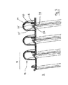
- eine zur Verwendung an dem Staubsauger vorgesehene, gewickelte Schlauchleitung nach einer ersten Ausbildung der Erfindung in seitlicher Ansicht (
Fig. 2a ), in seitlichem Schnitt (Fig. 2b ) und in perspektivischer Ansicht (Fig. 2c ) und schließlich - Fig. 3
- eine Variante der in
Fig. 2 dargestellten Schlauchleitung. - Bei der nachfolgenden Beschreibung von zwei bevorzugten Ausführungsformen der vorliegenden Erfindung bezeichnen gleiche Bezugszeichen gleiche oder vergleichbare Komponenten.
- Der in
Fig. 1 dargestellte Staubsauger 1 ist als Bodenstaubsauger ausgebildet. Grundsätzlich ist die Erfindung jedoch auch bei anderen Bauformen, beispielsweise einem mit einer flexiblen Saugrohrverlängerung ausgestatteten Stielstaubsauger, mit Vorteil einsetzbar. - Der Staubsauger 1 nach
Fig. 1 besteht aus einem gesonderten Aggregateträger 2, welcher mit einem Fahrwerk 3 ausgestattet ist und damit komfortabel über die zu reinigende Bodenfläche bewegt werden kann. Das Gehäuse 4 des Aggregateträgers 2 nimmt insbesondere ein Sauggebläse 5 und eine Staubabscheideeinrichtung 6 in Form eines Staubfilterbeutels 7 auf. Weitere, nicht gezeigt Komponenten des Aggregateträgers sind beispielsweise ein aufwickelbares Stromkabel zur elektrischen Verbindung mit einem Stromnetz, Stelleinrichtungen zum Einschalten und zur Leistungseinstellung, elektronische Regelungseinrichtungen und ein Staufach für Zubehör wie Saugbürsten oder dergleichen. - Stromauf der Staubabscheideeinrichtung 6 ist ein Anschluss 8 zum Anbringen eines biegsamen Saugschlauches 9 vorgesehen, welcher seinerseits mit einem telekopierbaren Schubrohr 10 strömungsverbunden ist. Das Schubrohr 10 ist gedichtet in einen Anschlussstutzen 11 der Saugdüse 12 eingeschoben. Stromauf des gelenkig mit der übrigen Saugdüse 12 verbundenen Anschlussstutzens 11 weist die Saugdüse 12 ferner ein Saugdüsengehäuse 13 und eine über die zu reinigende Bodenfläche zu führende Gleitsohle 14 mit einem Saugmund 15 auf. Die Saugdüse 12 ist ferner mit einer Rollenanordnung 16 zur Abstützung des Schubrohrs 10 versehen.
- Beim Reinigungsvorgang liegt die Gleitsohle 14 dichtend an der Bodenfläche an, wobei durch den am Saugmund 15 anliegenden Unterdruck ein Luftstrom angesaugt wird und den auf der Bodenfläche befindlichen Staub mitführt. Der Schmutz führende Luftstrom wird durch das Schubrohr 10 und den Saugschlauch 9 in die Staubabscheideeinrichtung 6 geleitet, wo der Staub im Staubfilterbeutel 7 abgeschieden wird. Der nunmehr gereinigte Luftstrom durchquert das Sauggebläse 5 und wird anschließend durch eine Öffnung 17 im Gehäuse 4 des Aggregateträgers 2 in die Umgebung abgeführt.
- Der in
Fig. 2 abgebildete Saugschlauch 9 ist aus einem aus Kunststoff extrudierten Profilstrang 18 helixförmig gewickelt, wobei der Profilstrang 18 im zur Verbindung vorgesehenen Stoßbereich durch Kleben dichtend verbunden ist. Der Profilstrang 18 weist an einem Rand einen U-förmig verlaufenden Bereich 19 mit einem endseitigen Schenkel 20 auf, der senkrecht zur Haupterstreckungsrichtung des Profilstangs 18 verläuft. Der Profilstrang 18 ist mit zwei Zungen 21, 21' versehen, die einstückig an diesen angeformt sind und sich näherungsweise in Haupterstreckungsrichtung des Profilstangs 18 voneinander weg erstrecken. Dabei ragt die erste Zunge 21 aus dem Profilstrang 18 ab, während sich die zweite Zunge 21' in den U-förmig verlaufenden Bereich 19 des Profilstrangs 18 hinein erstreckt. Beide Zungen 21, 21' verlaufen in ungespanntem Zustand jeweils linear, sind also im Ausführungsbeispiel nicht gekrümmt, und sind gegenüber der Haupterstreckungsrichtung des Profilstangs 18 sowie Längsachse 22 des fertigen, ungekrümmten Saugschlauches 9 unter einem Winkel von etwa 45° von der Längsachse 22 wegweisend geneigt. Ferner ist der Profilstrang 18 mit einer einstückig angeformten Lasche 23 ausgestattet, welche senkrecht zur Haupterstreckungsrichtung des Profilstangs 18 von der Längsachse 22 wegweisend ausgerichtet ist. - Bei der Fertigung des Saugschlauchs 9 wird der Profilsstrang 18 schraubenförmig aufgewickelt, wobei der Schenkel 20 einer Windung in Anlage an die Lasche 23 einer benachbarten Windung gelangt und mit dieser mittels Heißklebstoff durch Stoffschluss unlösbar und gasdicht verbunden wird. Der U-förmige Bereich 19 des Profilsstrangs 18 bildet nachfolgend das Wellental 24 des gewellten Saugschlauchs 9 aus, welches von den Zungen 21, 21' mit ihren nunmehr stumpf aufeinander stoßenden freien Enden 25, 25' dichtend überdeckt wird. Die freien Enden 25, 25' der Zungen 21, 21' stehen dabei derart in linienförmigem Kontakt, dass sie entlang ihrer im Wesentlichen gesamten Längserstreckung aufeinander stoßen. Die Neigung der Zungen 21, 21' relativ zu der Längsachse 22 kann sich dabei durch elastische Verformung, vorzugsweise ein Krümmen der Zungen 21, 21' erhöhen, um die gewünschte Vorspannung in der Anlage der freien Enden 25, 25' zu erzeugen. Ferner kann die Vorspannung durch eine elastische Biegung der an sich geradlinig verlaufenden Zungen 21, 21' hervorgerufen werden. Dabei verbleiben die freien Enden 25, 25' in linienförmigem Kontakt.
- Durch die aufeinander stoßenden Zungen 21, 21' wird der Saugschlauch 9 innen pneumatisch glatter, wodurch sich der Strömungswiderstand und damit der Druckverlust beim Staubsaugen verringern. Ferner wird der durch Ablagerung von Staub und anderen Verschmutzungen bedrohte Raum im Saugschlauch 9 erheblich verringert. Bei einer Biegung des Saugschlauchs 9 verformt sich zunächst der U-förmige Bereich 19 und damit das Wellental 24, welches insbesondere auf der Innenseite der Krümmung gestaucht wird. Die Außenseite des Schlauchs wird hingegen gestreckt, indem sich das Wellental 24 dort erweitert.
- In einer beispielhaften Ausführung der Erfindung spannen sich die Zungen 21, 21' dabei weiter, ohne dass sich die Lage ihrer freien Enden 25, 25' zueinander und damit die Kontaktsituation zwischen den Zungen 21, 21' nennenswert ändert. Insbesondere wird vermieden, dass die Zungen 21, 21' entlang ihrer Flächenseiten aufeinander gleiten. Die Verbreiterung des Wellentals 24 auf der Außenseite der Krümmung wird durch Aufzehren der Vorspannung in den Zungen 21, 21' kompensiert, so dass deren freien Enden 25, 25' weiterhin aufeinander stoßen.
- In der in
Fig. 3 dargestellten Variante der Schlauchleitung derFig. 1 stößt die Kante 25 einer Zunge 21 nicht auf die Kante 25' sondern eine Fläche der anderen Zunge 21'. Auch in diesem Fall stehen die Kante 25 der einen Zunge 21 und die Fläche des anderen Zunge 21' in linienförmigem Kontakt. Beim Krümmen der Schlauchleitung kann sich die Kante 25 der einen Zunge 21 auf der Fläche der anderen Zunge 21' verlagern, wobei die beiden Zungen aber jedenfalls aber jedenfalls in linienförmigem Kontakt bleiben. - Mit der Erfindung kann die Barrierewirkung im Wellental 24 verbessert werden, ohne dass die Flexibilität der Schlauchleitung 9 selbst bei stärkerer Biegung nennenswert beeinträchtigt wird. Insbesondere können Staubablagerungen und Geräuschentwicklung entgegengewirkt werden. Die in der vorstehenden Beschreibung, den Ansprüchen und den Zeichnungen offenbarten Merkmale können sowohl einzeln als auch in beliebiger Kombination für die Verwirklichung der Erfindung in ihren verschiedenen Ausgestaltungen von Bedeutung sein.
-
- 1
- Staubsauger
- 2
- Aggregateträger
- 3
- Fahrwerk
- 4
- Gehäuse
- 5
- Sauggebläse
- 6
- Staubabscheideeinrichtung
- 7
- Staubfilterbeutel
- 8
- Anschluss
- 9
- Saugschlauch
- 10
- Schubrohr
- 11
- Anschlussstutzen
- 12
- Saugdüse
- 13
- Saugdüsengehäuse
- 14
- Gleitsohle
- 15
- Saugmund
- 16
- Rollenanordnung
- 17
- Öffnung
- 18
- Profilstrang
- 19
- Bereich (des Profilstrangs)
- 20
- Schenkel
- 21, 21'
- Zunge
- 22
- Längsachse (des Saugschlauchs)
- 23
- Lasche
- 24
- Wellental
- 25, 25'
- freies Ende (der Zunge)
Claims (10)
- Schlauchleitung mit einer in Längsrichtung gewellten, innere Wellentäler (24) aufweisenden Wandung, insbesondere zur Verwendung als Saugschlauch (9) an einem Staubsauger (1), wobei im Bereich der inneren Wellentäler (24) zur pneumatischen und/oder hydraulischen Glättung der Schlauchleitung eine Barriere in Form von einander gegenüberliegend in Richtung des Wellentals (24) auskragenden und das Wellental (24) überdeckenden Zungen (21, 21') vorgesehen ist,
dadurch gekennzeichnet, dass
die Zungen (21, 21') unter elastischer Vorspannung stumpf aufeinander stoßend ausgebildet sind. - Schlauchleitung nach Anspruch 1, dadurch gekennzeichnet, dass die Schlauchleitung aus einem helixförmig gewickelten Profilstrang (18) besteht.
- Schlauchleitung nach Anspruch 2, dadurch gekennzeichnet, dass die Zungen (21, 21') einstückig an den Profilstrang (18) oder die Ringelemente (26) angeformt sind.
- Schlauchleitung nach Anspruch 2 oder 3, dadurch gekennzeichnet, dass der Profilstrang (18) einen Schenkel (20) und eine Lasche (23) aufweist, wobei der Schenkel (20) einer Windung sich mit der Lasche (23) einer benachbarten Windung in Anlage befindet und mit dieser fest verbunden ist.
- Schlauchleitung nach einem der vorhergehenden Ansprüche, dadurch gekennzeichnet, dass die Zungen (21, 21') in ungespanntem Zustand jeweils linear verlaufen.
- Schlauchleitung nach einem der vorhergehenden Ansprüche, dadurch gekennzeichnet, dass die Zungen (21, 21') gegenüber der Längsachse (22) der ungekrümmten Schlauchleitung geneigt ausgerichtet sind.
- Schlauchleitung nach einem der vorhergehenden Ansprüche, dadurch gekennzeichnet, dass die Zungen (21, 21') von der Längsachse (22) der ungekrümmten Schlauchleitung wegweisend ausgerichtet sind.
- Schlauchleitung nach einem der vorhergehenden Ansprüche, dadurch gekennzeichnet, dass die Zungen (21, 21') voneinander wegweisend an den Profilstrang (18) oder die Ringelemente (26) angeformt sind.
- Schlauchleitung nach einem der vorhergehenden Ansprüche, dadurch gekennzeichnet, dass eine Zunge (21') in den nachfolgend das Wellental (24) der Schlauchleitungen bildenden Bereich (19) auskragend an den Profilstrangs (18) oder das Ringelement (26) angeformt ist.
- Staubsauger (1) mit einer als Saugschlauch (9) dienenden Schlauchleitung nach einem der vorhergehenden Ansprüche.
Applications Claiming Priority (1)
| Application Number | Priority Date | Filing Date | Title |
|---|---|---|---|
| DE102011084197A DE102011084197A1 (de) | 2011-10-10 | 2011-10-10 | Schlauchleitung mit überdeckenden Zungen, insbesondere für einen Staubsauger |
Publications (3)
| Publication Number | Publication Date |
|---|---|
| EP2581024A2 true EP2581024A2 (de) | 2013-04-17 |
| EP2581024A3 EP2581024A3 (de) | 2014-09-10 |
| EP2581024B1 EP2581024B1 (de) | 2016-01-20 |
Family
ID=47008401
Family Applications (1)
| Application Number | Title | Priority Date | Filing Date |
|---|---|---|---|
| EP12187822.7A Not-in-force EP2581024B1 (de) | 2011-10-10 | 2012-10-09 | Schlauchleitung mit überdeckenden Zungen, insbesondere für einen Staubsauger |
Country Status (2)
| Country | Link |
|---|---|
| EP (1) | EP2581024B1 (de) |
| DE (1) | DE102011084197A1 (de) |
Cited By (1)
| Publication number | Priority date | Publication date | Assignee | Title |
|---|---|---|---|---|
| EP4298971A1 (de) * | 2022-06-30 | 2024-01-03 | Hilti Aktiengesellschaft | Saugschlauch für einen staubsauger und herstellungsverfahren dafür |
Citations (4)
| Publication number | Priority date | Publication date | Assignee | Title |
|---|---|---|---|---|
| EP1407707A2 (de) | 2002-10-11 | 2004-04-14 | Dr. Kern GmbH | Saugschlauch |
| US20040096616A1 (en) | 2002-11-12 | 2004-05-20 | Il-Sook Park | Flexible hose for a vacuum cleaner and fabricating method thereof |
| WO2010086819A1 (en) | 2009-01-28 | 2010-08-05 | Plastiflex Belgium | Flexible hose with smooth inner and/or outer wall |
| DE202009009809U1 (de) | 2009-07-17 | 2010-11-25 | Schonath, Andreas | Aus einem Außenschlauch und einem Innenschlauch bestehender Verbundschlauch |
Family Cites Families (2)
| Publication number | Priority date | Publication date | Assignee | Title |
|---|---|---|---|---|
| US3273600A (en) * | 1963-06-10 | 1966-09-20 | Air Reduction | Flexible tube |
| US4471813A (en) * | 1980-04-04 | 1984-09-18 | Dayco Corporation | Hose construction |
-
2011
- 2011-10-10 DE DE102011084197A patent/DE102011084197A1/de not_active Ceased
-
2012
- 2012-10-09 EP EP12187822.7A patent/EP2581024B1/de not_active Not-in-force
Patent Citations (4)
| Publication number | Priority date | Publication date | Assignee | Title |
|---|---|---|---|---|
| EP1407707A2 (de) | 2002-10-11 | 2004-04-14 | Dr. Kern GmbH | Saugschlauch |
| US20040096616A1 (en) | 2002-11-12 | 2004-05-20 | Il-Sook Park | Flexible hose for a vacuum cleaner and fabricating method thereof |
| WO2010086819A1 (en) | 2009-01-28 | 2010-08-05 | Plastiflex Belgium | Flexible hose with smooth inner and/or outer wall |
| DE202009009809U1 (de) | 2009-07-17 | 2010-11-25 | Schonath, Andreas | Aus einem Außenschlauch und einem Innenschlauch bestehender Verbundschlauch |
Cited By (2)
| Publication number | Priority date | Publication date | Assignee | Title |
|---|---|---|---|---|
| EP4298971A1 (de) * | 2022-06-30 | 2024-01-03 | Hilti Aktiengesellschaft | Saugschlauch für einen staubsauger und herstellungsverfahren dafür |
| WO2024002722A1 (de) * | 2022-06-30 | 2024-01-04 | Hilti Aktiengesellschaft | Saugschlauch für einen staubsauger und herstellungsverfahren dafür |
Also Published As
| Publication number | Publication date |
|---|---|
| DE102011084197A1 (de) | 2013-04-11 |
| EP2581024A3 (de) | 2014-09-10 |
| EP2581024B1 (de) | 2016-01-20 |
Similar Documents
| Publication | Publication Date | Title |
|---|---|---|
| EP0611544B1 (de) | Einteilige Staubsaugerdüse | |
| EP2449935B1 (de) | Saugdüse und Bodenstaubsauger | |
| DE102007010517A1 (de) | Düse für einen Bodenstaubsauger | |
| EP1367931B1 (de) | Kippgelenkausbildung eines staubsauger-saugkanals | |
| EP3097763B1 (de) | Fahrzeug mit knicklenkung und saugschlauch | |
| EP3218972A1 (de) | Wellrohranordnung zur aufnahme von leitungen und verfahren zur herstellung einer solchen wellrohranordnung | |
| EP2581024B1 (de) | Schlauchleitung mit überdeckenden Zungen, insbesondere für einen Staubsauger | |
| EP1872702B1 (de) | Teleskopierbares Staubsauger-Saugrohr | |
| EP2330961B1 (de) | Staubsaugerschlauch und schlauchaufsatz für einen staubsauger mit erhöhter saugleistung | |
| EP1286096A2 (de) | Kunststoffkorrugationswellrohr mit monolithischem Behältnis | |
| EP2584238B1 (de) | Schlauchleitung mit elastischem Hohlprofil, insbesondere für einen Staubsauger | |
| DE102011084195B4 (de) | Ausgeschäumte Schlauchleitung, insbesondere für einen Staubsauger | |
| DE102010040056B4 (de) | Saugrohrteil eines Staubsaugers | |
| EP2581023B1 (de) | Schlauchleitung mit Zunge, insbesondere für einen Staubsauger | |
| DE3705292C1 (de) | Flexibler Schlauch | |
| EP1407707A2 (de) | Saugschlauch | |
| DE69806425T2 (de) | Schlauchanordnungen | |
| DE102019102357B4 (de) | Vorrichtung zur Absperrung oder Steuerung des Durchflusses von schmutzbeladener Luft, Reinigungsgerät und Behältnis zum Abtrennen und/oder Sammeln von Schmutz mit einer solchen Vorrichtung | |
| EP0607504B1 (de) | Hochdruckreinigungsgerät | |
| DE202008008786U1 (de) | Dichte Verbindung für einen Staubsauger | |
| EP2436502A2 (de) | Verfahren zur Herstellung eines flexiblen Saugschlauches und hergestelletes Saugschlauch | |
| EP2669074B1 (de) | Hohlkörperverbindung mit zwei Hohlkörpern, die mittels eines Blasformverfahrens hergestellt sind | |
| EP2260228B1 (de) | Rückstandssammler | |
| EP1333214A1 (de) | Anschlusseinrichtung zum wasserdichten Anschliessen eines Wellrohres | |
| DE102011077275B4 (de) | Saugdüse mit Balgen |
Legal Events
| Date | Code | Title | Description |
|---|---|---|---|
| PUAI | Public reference made under article 153(3) epc to a published international application that has entered the european phase |
Free format text: ORIGINAL CODE: 0009012 |
|
| AK | Designated contracting states |
Kind code of ref document: A2 Designated state(s): AL AT BE BG CH CY CZ DE DK EE ES FI FR GB GR HR HU IE IS IT LI LT LU LV MC MK MT NL NO PL PT RO RS SE SI SK SM TR |
|
| AX | Request for extension of the european patent |
Extension state: BA ME |
|
| PUAL | Search report despatched |
Free format text: ORIGINAL CODE: 0009013 |
|
| AK | Designated contracting states |
Kind code of ref document: A3 Designated state(s): AL AT BE BG CH CY CZ DE DK EE ES FI FR GB GR HR HU IE IS IT LI LT LU LV MC MK MT NL NO PL PT RO RS SE SI SK SM TR |
|
| AX | Request for extension of the european patent |
Extension state: BA ME |
|
| RIC1 | Information provided on ipc code assigned before grant |
Ipc: A47L 9/24 20060101AFI20140805BHEP Ipc: F16L 11/15 20060101ALI20140805BHEP Ipc: F16L 11/16 20060101ALI20140805BHEP |
|
| RAP1 | Party data changed (applicant data changed or rights of an application transferred) |
Owner name: BSH HAUSGERAETE GMBH |
|
| 17P | Request for examination filed |
Effective date: 20150310 |
|
| RBV | Designated contracting states (corrected) |
Designated state(s): AL AT BE BG CH CY CZ DE DK EE ES FI FR GB GR HR HU IE IS IT LI LT LU LV MC MK MT NL NO PL PT RO RS SE SI SK SM TR |
|
| GRAP | Despatch of communication of intention to grant a patent |
Free format text: ORIGINAL CODE: EPIDOSNIGR1 |
|
| INTG | Intention to grant announced |
Effective date: 20150724 |
|
| GRAS | Grant fee paid |
Free format text: ORIGINAL CODE: EPIDOSNIGR3 |
|
| GRAA | (expected) grant |
Free format text: ORIGINAL CODE: 0009210 |
|
| AK | Designated contracting states |
Kind code of ref document: B1 Designated state(s): AL AT BE BG CH CY CZ DE DK EE ES FI FR GB GR HR HU IE IS IT LI LT LU LV MC MK MT NL NO PL PT RO RS SE SI SK SM TR |
|
| REG | Reference to a national code |
Ref country code: GB Ref legal event code: FG4D Free format text: NOT ENGLISH |
|
| REG | Reference to a national code |
Ref country code: CH Ref legal event code: EP |
|
| REG | Reference to a national code |
Ref country code: IE Ref legal event code: FG4D Free format text: LANGUAGE OF EP DOCUMENT: GERMAN |
|
| REG | Reference to a national code |
Ref country code: AT Ref legal event code: REF Ref document number: 771325 Country of ref document: AT Kind code of ref document: T Effective date: 20160215 |
|
| REG | Reference to a national code |
Ref country code: DE Ref legal event code: R096 Ref document number: 502012005772 Country of ref document: DE |
|
| REG | Reference to a national code |
Ref country code: LT Ref legal event code: MG4D Ref country code: NL Ref legal event code: MP Effective date: 20160120 |
|
| PG25 | Lapsed in a contracting state [announced via postgrant information from national office to epo] |
Ref country code: NL Free format text: LAPSE BECAUSE OF FAILURE TO SUBMIT A TRANSLATION OF THE DESCRIPTION OR TO PAY THE FEE WITHIN THE PRESCRIBED TIME-LIMIT Effective date: 20160120 |
|
| PG25 | Lapsed in a contracting state [announced via postgrant information from national office to epo] |
Ref country code: NO Free format text: LAPSE BECAUSE OF FAILURE TO SUBMIT A TRANSLATION OF THE DESCRIPTION OR TO PAY THE FEE WITHIN THE PRESCRIBED TIME-LIMIT Effective date: 20160420 Ref country code: GR Free format text: LAPSE BECAUSE OF FAILURE TO SUBMIT A TRANSLATION OF THE DESCRIPTION OR TO PAY THE FEE WITHIN THE PRESCRIBED TIME-LIMIT Effective date: 20160421 Ref country code: FI Free format text: LAPSE BECAUSE OF FAILURE TO SUBMIT A TRANSLATION OF THE DESCRIPTION OR TO PAY THE FEE WITHIN THE PRESCRIBED TIME-LIMIT Effective date: 20160120 Ref country code: ES Free format text: LAPSE BECAUSE OF FAILURE TO SUBMIT A TRANSLATION OF THE DESCRIPTION OR TO PAY THE FEE WITHIN THE PRESCRIBED TIME-LIMIT Effective date: 20160120 Ref country code: IT Free format text: LAPSE BECAUSE OF FAILURE TO SUBMIT A TRANSLATION OF THE DESCRIPTION OR TO PAY THE FEE WITHIN THE PRESCRIBED TIME-LIMIT Effective date: 20160120 Ref country code: HR Free format text: LAPSE BECAUSE OF FAILURE TO SUBMIT A TRANSLATION OF THE DESCRIPTION OR TO PAY THE FEE WITHIN THE PRESCRIBED TIME-LIMIT Effective date: 20160120 |
|
| PG25 | Lapsed in a contracting state [announced via postgrant information from national office to epo] |
Ref country code: SE Free format text: LAPSE BECAUSE OF FAILURE TO SUBMIT A TRANSLATION OF THE DESCRIPTION OR TO PAY THE FEE WITHIN THE PRESCRIBED TIME-LIMIT Effective date: 20160120 Ref country code: LV Free format text: LAPSE BECAUSE OF FAILURE TO SUBMIT A TRANSLATION OF THE DESCRIPTION OR TO PAY THE FEE WITHIN THE PRESCRIBED TIME-LIMIT Effective date: 20160120 Ref country code: LT Free format text: LAPSE BECAUSE OF FAILURE TO SUBMIT A TRANSLATION OF THE DESCRIPTION OR TO PAY THE FEE WITHIN THE PRESCRIBED TIME-LIMIT Effective date: 20160120 Ref country code: PL Free format text: LAPSE BECAUSE OF FAILURE TO SUBMIT A TRANSLATION OF THE DESCRIPTION OR TO PAY THE FEE WITHIN THE PRESCRIBED TIME-LIMIT Effective date: 20160120 Ref country code: PT Free format text: LAPSE BECAUSE OF FAILURE TO SUBMIT A TRANSLATION OF THE DESCRIPTION OR TO PAY THE FEE WITHIN THE PRESCRIBED TIME-LIMIT Effective date: 20160520 Ref country code: IS Free format text: LAPSE BECAUSE OF FAILURE TO SUBMIT A TRANSLATION OF THE DESCRIPTION OR TO PAY THE FEE WITHIN THE PRESCRIBED TIME-LIMIT Effective date: 20160520 Ref country code: RS Free format text: LAPSE BECAUSE OF FAILURE TO SUBMIT A TRANSLATION OF THE DESCRIPTION OR TO PAY THE FEE WITHIN THE PRESCRIBED TIME-LIMIT Effective date: 20160120 |
|
| REG | Reference to a national code |
Ref country code: DE Ref legal event code: R097 Ref document number: 502012005772 Country of ref document: DE |
|
| REG | Reference to a national code |
Ref country code: FR Ref legal event code: PLFP Year of fee payment: 5 |
|
| PG25 | Lapsed in a contracting state [announced via postgrant information from national office to epo] |
Ref country code: EE Free format text: LAPSE BECAUSE OF FAILURE TO SUBMIT A TRANSLATION OF THE DESCRIPTION OR TO PAY THE FEE WITHIN THE PRESCRIBED TIME-LIMIT Effective date: 20160120 Ref country code: DK Free format text: LAPSE BECAUSE OF FAILURE TO SUBMIT A TRANSLATION OF THE DESCRIPTION OR TO PAY THE FEE WITHIN THE PRESCRIBED TIME-LIMIT Effective date: 20160120 |
|
| PLBE | No opposition filed within time limit |
Free format text: ORIGINAL CODE: 0009261 |
|
| STAA | Information on the status of an ep patent application or granted ep patent |
Free format text: STATUS: NO OPPOSITION FILED WITHIN TIME LIMIT |
|
| PG25 | Lapsed in a contracting state [announced via postgrant information from national office to epo] |
Ref country code: RO Free format text: LAPSE BECAUSE OF FAILURE TO SUBMIT A TRANSLATION OF THE DESCRIPTION OR TO PAY THE FEE WITHIN THE PRESCRIBED TIME-LIMIT Effective date: 20160120 Ref country code: CZ Free format text: LAPSE BECAUSE OF FAILURE TO SUBMIT A TRANSLATION OF THE DESCRIPTION OR TO PAY THE FEE WITHIN THE PRESCRIBED TIME-LIMIT Effective date: 20160120 Ref country code: SK Free format text: LAPSE BECAUSE OF FAILURE TO SUBMIT A TRANSLATION OF THE DESCRIPTION OR TO PAY THE FEE WITHIN THE PRESCRIBED TIME-LIMIT Effective date: 20160120 Ref country code: SM Free format text: LAPSE BECAUSE OF FAILURE TO SUBMIT A TRANSLATION OF THE DESCRIPTION OR TO PAY THE FEE WITHIN THE PRESCRIBED TIME-LIMIT Effective date: 20160120 |
|
| 26N | No opposition filed |
Effective date: 20161021 |
|
| PG25 | Lapsed in a contracting state [announced via postgrant information from national office to epo] |
Ref country code: BG Free format text: LAPSE BECAUSE OF FAILURE TO SUBMIT A TRANSLATION OF THE DESCRIPTION OR TO PAY THE FEE WITHIN THE PRESCRIBED TIME-LIMIT Effective date: 20160420 Ref country code: BE Free format text: LAPSE BECAUSE OF NON-PAYMENT OF DUE FEES Effective date: 20161031 Ref country code: SI Free format text: LAPSE BECAUSE OF FAILURE TO SUBMIT A TRANSLATION OF THE DESCRIPTION OR TO PAY THE FEE WITHIN THE PRESCRIBED TIME-LIMIT Effective date: 20160120 |
|
| REG | Reference to a national code |
Ref country code: CH Ref legal event code: PL |
|
| REG | Reference to a national code |
Ref country code: IE Ref legal event code: MM4A |
|
| PG25 | Lapsed in a contracting state [announced via postgrant information from national office to epo] |
Ref country code: LI Free format text: LAPSE BECAUSE OF NON-PAYMENT OF DUE FEES Effective date: 20161031 Ref country code: CH Free format text: LAPSE BECAUSE OF NON-PAYMENT OF DUE FEES Effective date: 20161031 |
|
| PG25 | Lapsed in a contracting state [announced via postgrant information from national office to epo] |
Ref country code: LU Free format text: LAPSE BECAUSE OF NON-PAYMENT OF DUE FEES Effective date: 20161009 |
|
| REG | Reference to a national code |
Ref country code: FR Ref legal event code: PLFP Year of fee payment: 6 |
|
| PG25 | Lapsed in a contracting state [announced via postgrant information from national office to epo] |
Ref country code: IE Free format text: LAPSE BECAUSE OF NON-PAYMENT OF DUE FEES Effective date: 20161009 |
|
| REG | Reference to a national code |
Ref country code: BE Ref legal event code: MM Effective date: 20161031 |
|
| PG25 | Lapsed in a contracting state [announced via postgrant information from national office to epo] |
Ref country code: HU Free format text: LAPSE BECAUSE OF FAILURE TO SUBMIT A TRANSLATION OF THE DESCRIPTION OR TO PAY THE FEE WITHIN THE PRESCRIBED TIME-LIMIT; INVALID AB INITIO Effective date: 20121009 Ref country code: CY Free format text: LAPSE BECAUSE OF FAILURE TO SUBMIT A TRANSLATION OF THE DESCRIPTION OR TO PAY THE FEE WITHIN THE PRESCRIBED TIME-LIMIT Effective date: 20160120 |
|
| PG25 | Lapsed in a contracting state [announced via postgrant information from national office to epo] |
Ref country code: TR Free format text: LAPSE BECAUSE OF FAILURE TO SUBMIT A TRANSLATION OF THE DESCRIPTION OR TO PAY THE FEE WITHIN THE PRESCRIBED TIME-LIMIT Effective date: 20160120 Ref country code: MK Free format text: LAPSE BECAUSE OF FAILURE TO SUBMIT A TRANSLATION OF THE DESCRIPTION OR TO PAY THE FEE WITHIN THE PRESCRIBED TIME-LIMIT Effective date: 20160120 Ref country code: MT Free format text: LAPSE BECAUSE OF FAILURE TO SUBMIT A TRANSLATION OF THE DESCRIPTION OR TO PAY THE FEE WITHIN THE PRESCRIBED TIME-LIMIT Effective date: 20160120 Ref country code: MC Free format text: LAPSE BECAUSE OF FAILURE TO SUBMIT A TRANSLATION OF THE DESCRIPTION OR TO PAY THE FEE WITHIN THE PRESCRIBED TIME-LIMIT Effective date: 20160120 |
|
| REG | Reference to a national code |
Ref country code: FR Ref legal event code: PLFP Year of fee payment: 7 |
|
| PG25 | Lapsed in a contracting state [announced via postgrant information from national office to epo] |
Ref country code: AL Free format text: LAPSE BECAUSE OF FAILURE TO SUBMIT A TRANSLATION OF THE DESCRIPTION OR TO PAY THE FEE WITHIN THE PRESCRIBED TIME-LIMIT Effective date: 20160120 |
|
| REG | Reference to a national code |
Ref country code: AT Ref legal event code: MM01 Ref document number: 771325 Country of ref document: AT Kind code of ref document: T Effective date: 20171009 |
|
| PG25 | Lapsed in a contracting state [announced via postgrant information from national office to epo] |
Ref country code: AT Free format text: LAPSE BECAUSE OF NON-PAYMENT OF DUE FEES Effective date: 20171009 |
|
| PGFP | Annual fee paid to national office [announced via postgrant information from national office to epo] |
Ref country code: FR Payment date: 20221020 Year of fee payment: 11 |
|
| PGFP | Annual fee paid to national office [announced via postgrant information from national office to epo] |
Ref country code: GB Payment date: 20221024 Year of fee payment: 11 Ref country code: DE Payment date: 20221031 Year of fee payment: 11 |
|
| REG | Reference to a national code |
Ref country code: DE Ref legal event code: R119 Ref document number: 502012005772 Country of ref document: DE |
|
| GBPC | Gb: european patent ceased through non-payment of renewal fee |
Effective date: 20231009 |
|
| PG25 | Lapsed in a contracting state [announced via postgrant information from national office to epo] |
Ref country code: GB Free format text: LAPSE BECAUSE OF NON-PAYMENT OF DUE FEES Effective date: 20231009 |
|
| PG25 | Lapsed in a contracting state [announced via postgrant information from national office to epo] |
Ref country code: GB Free format text: LAPSE BECAUSE OF NON-PAYMENT OF DUE FEES Effective date: 20231009 Ref country code: FR Free format text: LAPSE BECAUSE OF NON-PAYMENT OF DUE FEES Effective date: 20231031 Ref country code: DE Free format text: LAPSE BECAUSE OF NON-PAYMENT OF DUE FEES Effective date: 20240501 |