EP2580552B1 - A heat exchanger - Google Patents
A heat exchanger Download PDFInfo
- Publication number
- EP2580552B1 EP2580552B1 EP11721039.3A EP11721039A EP2580552B1 EP 2580552 B1 EP2580552 B1 EP 2580552B1 EP 11721039 A EP11721039 A EP 11721039A EP 2580552 B1 EP2580552 B1 EP 2580552B1
- Authority
- EP
- European Patent Office
- Prior art keywords
- heat exchanger
- flow
- plates
- exchanger plates
- fluid
- Prior art date
- Legal status (The legal status is an assumption and is not a legal conclusion. Google has not performed a legal analysis and makes no representation as to the accuracy of the status listed.)
- Not-in-force
Links
- 239000012530 fluid Substances 0.000 claims description 60
- 238000000034 method Methods 0.000 claims description 10
- 238000010008 shearing Methods 0.000 claims description 6
- 238000004519 manufacturing process Methods 0.000 claims description 5
- 238000005304 joining Methods 0.000 claims description 4
- 239000000463 material Substances 0.000 claims description 3
- 238000009826 distribution Methods 0.000 description 15
- 230000000694 effects Effects 0.000 description 6
- 239000007787 solid Substances 0.000 description 3
- 230000015572 biosynthetic process Effects 0.000 description 2
- 230000015556 catabolic process Effects 0.000 description 2
- 238000001816 cooling Methods 0.000 description 2
- 238000006731 degradation reaction Methods 0.000 description 2
- 238000009434 installation Methods 0.000 description 2
- 230000001133 acceleration Effects 0.000 description 1
- 230000006835 compression Effects 0.000 description 1
- 238000007906 compression Methods 0.000 description 1
- 238000010276 construction Methods 0.000 description 1
- 230000001419 dependent effect Effects 0.000 description 1
- 238000009713 electroplating Methods 0.000 description 1
- 238000003475 lamination Methods 0.000 description 1
- 238000010248 power generation Methods 0.000 description 1
- 238000000926 separation method Methods 0.000 description 1
- 238000009966 trimming Methods 0.000 description 1
- 238000009827 uniform distribution Methods 0.000 description 1
Images


Classifications
-
- F—MECHANICAL ENGINEERING; LIGHTING; HEATING; WEAPONS; BLASTING
- F28—HEAT EXCHANGE IN GENERAL
- F28F—DETAILS OF HEAT-EXCHANGE AND HEAT-TRANSFER APPARATUS, OF GENERAL APPLICATION
- F28F9/00—Casings; Header boxes; Auxiliary supports for elements; Auxiliary members within casings
- F28F9/02—Header boxes; End plates
- F28F9/026—Header boxes; End plates with static flow control means, e.g. with means for uniformly distributing heat exchange media into conduits
- F28F9/0265—Header boxes; End plates with static flow control means, e.g. with means for uniformly distributing heat exchange media into conduits by using guiding means or impingement means inside the header box
-
- F—MECHANICAL ENGINEERING; LIGHTING; HEATING; WEAPONS; BLASTING
- F28—HEAT EXCHANGE IN GENERAL
- F28D—HEAT-EXCHANGE APPARATUS, NOT PROVIDED FOR IN ANOTHER SUBCLASS, IN WHICH THE HEAT-EXCHANGE MEDIA DO NOT COME INTO DIRECT CONTACT
- F28D9/00—Heat-exchange apparatus having stationary plate-like or laminated conduit assemblies for both heat-exchange media, the media being in contact with different sides of a conduit wall
- F28D9/0031—Heat-exchange apparatus having stationary plate-like or laminated conduit assemblies for both heat-exchange media, the media being in contact with different sides of a conduit wall the conduits for one heat-exchange medium being formed by paired plates touching each other
- F28D9/0037—Heat-exchange apparatus having stationary plate-like or laminated conduit assemblies for both heat-exchange media, the media being in contact with different sides of a conduit wall the conduits for one heat-exchange medium being formed by paired plates touching each other the conduits for the other heat-exchange medium also being formed by paired plates touching each other
-
- Y—GENERAL TAGGING OF NEW TECHNOLOGICAL DEVELOPMENTS; GENERAL TAGGING OF CROSS-SECTIONAL TECHNOLOGIES SPANNING OVER SEVERAL SECTIONS OF THE IPC; TECHNICAL SUBJECTS COVERED BY FORMER USPC CROSS-REFERENCE ART COLLECTIONS [XRACs] AND DIGESTS
- Y10—TECHNICAL SUBJECTS COVERED BY FORMER USPC
- Y10T—TECHNICAL SUBJECTS COVERED BY FORMER US CLASSIFICATION
- Y10T29/00—Metal working
- Y10T29/49—Method of mechanical manufacture
- Y10T29/4935—Heat exchanger or boiler making
Definitions
- the present invention relates to a heat exchanger according to the preamble of claim 1 and particularly but not exclusively to a heat exchanger for use as an intercooler in a primary gas path of a gas turbine engine.
- FR 918616 discloses such an apparatus.
- a heat exchanger known as an intercooler
- the high pressure compressor can compress the gas with lower power input, thus improving the power output of the engine.
- Aerospace air-air heat exchangers typically only provide cooling to a small fraction of the engine core flow. Such heat exchangers are subject to considerable size and weight constraints. In a limited space, the heat exchanger may be installed in a V-shaped arrangement so as to increase the heat exchanger core frontal area. This may also reduce the flow path length within the heat exchanger and thus reduce the heat exchanger pressure losses.
- FIG. 1 is a top view of a heat exchanger installation of unit depth into the page.
- the heat exchangers 2 and 2' are installed in the same cross-sectional area A.
- Intercoolers used in industrial engines i.e. for power generation, are not subject to the space and weight constraints of aerospace applications. Consequently, these intercoolers may be comparable in size to the core engine and are capable of cooling the full engine core flow.
- JP2008151424 describes heat exchanger having laminations of corrugated plates.
- the ends of the corrugated plates include a passage changing part through which fluid flow enters the heat exchanger from a different direction to the passage defined by the corrugations.
- the arrangement is described as providing a greater resistance to fracture.
- the present invention seeks to provide a heat exchanger which optimises the flow path through the heat exchanger so as to promote heat transfer performance.
- a heat exchanger comprising: a heat exchanger core comprising a plurality of corrugated heat exchanger plates; the fluid path; a fluid path through the heat exchanger core, the fluid path running between adjacent heat exchanger plates and having an inlet at one side of the heat exchanger plates and an outlet at an opposing side of the heat exchanger plates; and a fluid guiding member adjacent to the inlet and/or outlet side of the heat exchanger plate of the fluid path, the fluid guiding member comprising an angled portion of each heat exchanger plate which is angled with respect to the remainder of the heat exchanger plate and being operable to change the direction of fluid flow, wherein the geometry of the heat exchanger plates is sheared such that the corrugations are not distorted by the angled portion.
- the fluid guiding member may change the direction of fluid flow by approximately 30 degrees at the inlet of the fluid path and/or approximately 75 degrees at the outlet of the fluid path.
- the fluid guiding member may provide a change in the flow direction at the inlet and/or outlet to the heat exchanger core. This provides a significant improvement in flow distribution within the heat exchanger core which improves the heat transfer performance of the heat exchanger. This is particularly significant in a heat exchanger core installed at a large angle relative to the manifold flow direction.
- the corrugations may promote turbulence and/or mixing within the flow, thus improving the heat transfer and the efficiency of the heat exchanger.
- the fluid guiding member may comprise a curved plate adjacent to the inlet and/or outlet side of one or more of the heat exchanger plates.
- the fluid guiding member may comprise an aerofoil portion which is located between the fluid paths of neighbouring pairs of heat exchanger plates.
- the angled portion with sheared geometry is most practical through turning angles up to 45 degrees. Although possible for larger angles the geometry may become less practical. Consequently, the curved plate and aerofoil portion guiding members may be used instead of or as well as the angled portion at these larger angles.
- Aerofoil portions may be located between alternate neighbouring pairs of heat exchanger plates.
- Aerofoil portions may be located between neighbouring pairs of hear exchanger plates, and the aerofoil portions of adjacent neighbouring pairs of heat exchanger plates may be dissimilar.
- This configuration provides turning of the flow whilst maintaining a suitably large mean free passage area.
- the fluid guiding member may be integral with the heat exchanger plates.
- the heat exchanger may be used in a gas turbine engine, particularly as an intercooler.
- a method of producing a cross-corrugated heat exchanger plate with an angled portion comprising: providing two sheets of material; forming corrugations at an oblique angle across a surface of each sheet; shearing the geometry of a portion of the sheets at the location of the angled portion; and joining the two sheets together.
- Shearing the geometry may comprise extruding the portion at an angle.
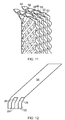
- FIG. 2 shows a heat exchanger 6 according to an embodiment of the invention.
- the heat exchanger 6 is a cross flow heat exchanger and comprises a heat exchanger core 8.
- the heat exchanger core 8 has a substantially rectangular cuboid shape.
- a first inlet header 14 and first outlet header 16 are fluidically coupled to the heat exchanger core 8 across long sides 18 of the rectangular cuboid.
- a second inlet header 10 and outlet header 12 are fluidically coupled to the heat exchanger core 8 across the opposing sides of the rectangular cuboid.
- the heat exchanger core 8 comprises a plurality of heat exchanger plates 20 (see Figure 4 ).
- the heat exchanger plates 20 extend across the heat exchanger core 8 between the inlet header 14 and outlet header 16.
- the heat exchanger plates 20 are oriented in a plane which is substantially parallel to the long sides 18 of the rectangular cuboid.
- Adjacent heat exchanger plates 20 form a fluid path through the heat exchanger core.
- the adjacent heat exchanger plates are closed along two sides to define the fluid path.
- Alternate pairs 22 of heat exchanger plates 20 are interconnected such that the fluid path runs from the inlet header 14 to the outlet header 16, with intermediate pairs 24 of heat exchanger plates 20 being interconnected such that the fluid path runs from the first narrow side 10 to the second narrow side 12.
- a first flow, Flow 1 passes through the heat exchanger core 8 from the inlet and outlet header 14, 16 between the alternate pairs 22 of heat exchanger plates 20.
- a second flow, Flow 2 passes through the heat exchanger core 8 from the first narrow side 10 to the second narrow side 12 between the intermediate pairs 24 of heat exchanger plates 20.
- the first flow, Flow 1 is a hot flow and the second flow, Flow 2, is a cold flow, or vice-versa.
- the hot and cold fluid paths cross each other at about 90 degrees within the heat exchanger core and heat is transferred from the hot flow to the cold flow.
- the first flow, Flow 1 enters the heat exchanger core 8 via the inlet header 14 and exits via the outlet header 16. Consequently, the path of the first flow, Flow 1, is a reverse C-shape, as shown in Figure 3 .
- a fluid guiding member for assisting flow through the heat exchanger.
- the actual embodiment described below is in relation to a flow path for Flow 2.
- the corresponding member for Flow 1 may comprise simple (i.e. planar) plates or walls.
- a flow guiding structure (as described below) may additionally or alternatively be applied to Flow 1.
- the features described below are applied to both Flows 1 and 2, subject to careful attention being paid to the manufacture/assembly at the corners of the flow guide structure to ensure that flow paths through the heat exchanger do not become blocked.
- a fluid guiding member is provided to assist the second flow, Flow 2, in turning from the direction of the inlet header 10 to the direction of the fluid path through the heat exchanger plates 20 and/or from the direction of the fluid path through the heat exchanger plates 20 to the direction of the outlet header 12.
- the fluid guiding member is provided by an angled portion 26 of each heat exchanger plate 20 adjacent to the inlet and/or outlet header 14, 16. The angled portion 26 is angled with respect to the remainder of the heat exchanger plate 20
- the heat exchanger plates 20 are provided with a series of corrugations 28 which run diagonally across the plates 20, i.e. at an oblique angle to the sides of the plate 20. Adjacent heat exchanger plates 20 are cross-corrugated such that their respective corrugations 28 run in opposite directions, crossing over one another at a point along their length.
- the cross-corrugated configuration of the heat exchanger plates 20 promotes turbulence and mixing within the flow, which improves heat transfer and thus improves the efficiency of the heat exchanger 6.
- the formation of the angled portion 26 would cause the orientation of the corrugations 28 to deviate along their length when viewed from in front of the heat exchanger plates 20.
- the geometry of the corrugations 26 is sheared such that, following the formation of the angled portion 26, peaks and troughs of the corrugations 28 appear linear, as shown in Figure 6 .
- points of the corrugations 28 along a line 30 where the angled portion 26 meets the remainder of the heat exchanger plate 20 remain fixed, whereas other points of the corrugations 28 are translated parallel to the line 30 by a distance proportional to their perpendicular distance from the line 30.
- Figure 7 shows a wire frame model of the front view of the heat exchanger plate 20 showing the effect on flow across the corrugations 28.
- the 2D flow pattern is not affected by the angled portion 26. Shearing the geometry also prevents mechanical distortion by maintaining the pattern of contact points between peaks of adjacent heat exchanger plates 20. This method maintains the flow path on both sides of the heat exchanger (Flow 1 and Flow 2).
- Figure 8 shows an embodiment of a method of constructing a heat exchanger plate 20.
- Corrugations 28 are formed in a surface of each of the two sheets 32 (step 2).
- the corrugations 28 are formed such that the corrugations 28 of the two sheets 32 are parallel when the un-corrugated surfaces of the two sheets 32 are facing each other.
- Sections 34 of the sheets which are to become the angled portion 26 are then sheared by extruding the sheets 32 at an angle (step 3).
- the angle at which the sheets 32 are extruded is dependent on the desired angle of the angled portion 26 with respect to the remainder of the heat exchanger plate 20. Furthermore, the direction of shear depends on which way the angled portion is to be angled. For example, where the heat exchanger plate 20 forms a "Z" shape with the inlet at the top of the "Z" and the outlet at the bottom of the "Z", the section 34 adjacent the inlet will be sheared in the opposite direction to the section 34 adjacent the outlet. Conversely, where the heat exchanger plate 20 forms a "C" shape, the section 34 adjacent the inlet and the section 34 adjacent the outlet will be sheared in the same direction.
- the two sheets are joined together (step 4) to form the heat exchanger plate 20 using a suitable joining process, with the un-corrugated surfaces of the two sheets 32 facing one another.
- the sheared sections 34 are angled in opposite directions. Consequently, the sheets 32 do not overlap in regions 36 at the sides of the sheared sections 34.
- the regions 36 where the sheets 32 do not overlap are removed by trimming the heat exchanger plate 20 to the desired size (step 5).
- Figure 9 provides a parameterisation which fully defines the corrugations 28 of the heat exchanger plates 20.
- the corrugations have an amplitude (the difference in height between a peak 38 and a trough 40) of 1.3mm and a wavelength (the separation between adjacent peaks 38) of 2.86mm.
- the peak 38 and troughs 40 have a radius of curvature of 0.286mm and are interconnected by angled sides.
- the corrugations of adjacent heat exchanger plates 20 are arranged in a cross-corrugated manner, such that their peaks and troughs are perpendicular to one another, as shown in view AB. Furthermore, the distance between peaks 38 of the adjacent heat exchanger plates 20 is 2.6mm as shown in view AC.
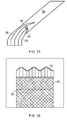
- FIG 10 shows an external fluid guiding member which may be used to change the direction of the flow either independently or in combination with the angled portion 26 described previously.
- This external fluid guiding member comprises a curved plate 42 adjacent to the inlet and/or outlet side of each of the heat exchanger plates 20.
- the curved plate 42 is an elongate plate which is coupled to the heat exchanger plates 20 along their inlet and/or outlet side and is curved from the plane of the heat exchanger plates 20 towards the desired direction of flow.
- the curved plate 42 may have a constant thickness.
- the curved plate 42 is located so as to change the direction of fluid flow at the outlet of the second flow, Flow 2. Furthermore, the curved plate 42 is shown in combination with the angled portions 26 which are used to change the direction of fluid flow at the inlet and outlet of the first flow, Flow 1. Consequently, the curved plate 42 is also profiled along the length of the heat exchanger plates 20 so that it conforms to the profile of the angled portions 26.
- FIG 11 shows another external fluid guiding member which may be used to change the direction of the flow either independently or in combination with the angled portion 26 described previously.
- This external fluid guiding member comprises an aerofoil portion 44. Whereas the curved plate 42 has a constant thickness, the aerofoil portion 44 tapers towards its end.
- the aerofoil portion 44 has an upper surface 46 and a lower surface 48 which join at a point 50.
- the upper surface 46 and lower surface 48 are corrugated with the peaks of the corrugations running in the direction of the bulk flow.
- An aerofoil portion 44 is located between the fluid paths of neighbouring pairs of heat exchanger plates 20, such that the fluid from one pair of heat exchanger plates 20 flows over the upper surface 46 and fluid from the other pair of heat exchanger plates 20 passes over the lower surface 48. As shown in Figure 11 , aerofoil portions 44 are located between alternate neighbouring pairs of heat exchanger plates 20.
- the pairs of heat exchanger plates 20 terminate in a flat surface 52, which is located at a position where the corrugations 28 of adjacent heat exchanger plates 20 are in phase.
- the flat surface 52 has an inner edge 53 and an outer edge 55 defined by the pair of heat exchanger plates 20.
- the outer edge 55 of the flat surface 52 is revolved about an axis positioned such that the surface of revolution is tangential to the outer edge 55 and at a radius chosen as a design parameter. Consequently, the upper surface 46 forms a continuous surface with the heat exchanger plate 20.
- the lower surface 48 of the aerofoil portion 44 is formed by revolving the inner edge 53 of the flat surface 52 about a separate axis positioned such that the surface of revolution is tangential to the inner edge 53 and at a radius chosen as a design parameter. Again, this creates a continuous surface between the heat exchanger plate 20 and the lower surface 48. For the pairs of heat exchanger plates 20 which do not have an aerofoil portion 44, the heat exchanger plates 20 terminate in the flat surface 52.
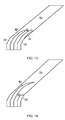
- a 2D section of the flow path between two pairs of heat exchanger plates 20 comprising an angled portion 26 is shown in Figure 12 .
- FIG. 13 An identical view is shown in Figure 13 for two pairs of heat exchanger plates 20 having both an angled portion 26 and an aerofoil portion 44. As shown, the aerofoil portions 44 have double circular arc aerofoil profile, however other profiles may be used.
- the mean free passage area 56 (i.e. the size of a sphere that is able to pass through the geometry) is reduced in the region of the aerofoil portions.
- the turning angle of the aerofoil portion 44 increases (i.e. a larger arc length) the free passage becomes more constricted.
- aerofoil portions 44 may be located between alternate neighbouring pairs of heat exchanger plates 20, particularly where a larger turning angle is required. Consequently, the mean free passage area 56 is increased, as shown in Figure 14 .
- a larger mean free passage area 56 reduces clogging in the heat exchanger core 8 leading to increased heat transfer.
- each neighbouring pair of heat exchanger plates 20 may be provided with an aerofoil portion 44, however, the aerofoil portions 44 of adjacent neighbouring pairs of heat exchanger plates may be dissimilar i.e. they have different arc lengths.
- This configuration provides turning of the flow whilst maintaining a suitably large mean free passage area 56, as shown in Figure 15 .
- Figure 16 shows the effect which the aerofoil portion 44 has on the flow through the heat exchanger.
- the aerofoil portion 44 turns the cross-corrugated flow in the plane of the bulk flow from the direction of the corrugations 28 to the bulk flow direction at the junction between the angled portion 26 and the aerofoil portion 44.
- This turning process results in a loss of total pressure.
- the bulk velocity is lower in the region of the heat exchanger plates 20 than in the region of the aerofoil portion 44 and consequently lower losses are experienced.
- This fluid guiding member configuration may be employed at both the inlet and outlet to the heat exchanger core. Therefore, as shown in Figure 18 , this configuration can be used to guide the flow from the direction of the inlet header 14 towards the plane of the heater exchanger plates 20 and also from this plane towards the direction of the outlet header 16.
- the flow is preferably rotated by an inlet angle of approximately 30 degrees and by an exit angle of approximately 75 degrees.
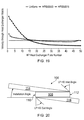
- Figure 19 is a graph showing the distribution of flow within the heat exchanger core 8. The graph plots the velocity through each of the heat exchanger plates 20 from the first short side 10 to the second short side 12.
- the "HP000000” line shows the distribution for a heat exchanger 6 without any fluid guiding means
- the "HP000075” line shows the distribution for a heat exchanger 6 with one or more of the fluid guiding members of the present invention which provide an exit angle of 75 degrees.
- the "HP000075" line has a far more even distribution of flow within the heat exchanger core 8 and thus more closely resembles the "Uniform" line.
- the fluid guiding members of the present invention therefore provide a more efficient heat exchanger 6 with improved heat transfer properties.
- FIG 20 shows a plan view of an alternative configuration of the heat exchanger. Whilst this embodiment is described as being separate to that of heat exchanger 6 of figure 2 for reasons of clarity, it will be appreciated that the view of figure 20 may also be considered representative of Flow path 2 of heat exchanger 6.
- a heat exchanger 106 comprises a heat exchanger core 108 and inlet and outlet headers 114, 116.
- the heat exchanger core 108 has a first short side 110 and a second short side 112.
- the heat exchanger core 108 comprises a plurality of heat exchanger plates 20 (not shown) which spaced between the first short side 110 and the second short side 112 and are oriented in a plane which runs between the inlet and outlet headers 114, 116.
- the headers 114, 116 are located on opposite sides the heat exchanger core 108 such that the flow path through the heat exchanger core follows a "Z" shaped path.
- one or more of the fluid guiding members of the present invention may be used to guide the flow from the direction of the inlet header 114 towards the plane of the heat exchanger plates 20 and also from this plane towards the direction of the outlet header 116.
- the flow is preferably rotated by an inlet angle of approximately 30 degrees and by an exit angle of approximately 75 degrees.
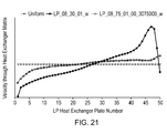
- Figure 21 is a graph showing the distribution of flow within the heat exchanger core 108. The graph plots the velocity through each of the heat exchanger plates 20 from the first short side 110 to the second short side 112.
- the idealised distribution is shown by the "Uniform" line.
- the "LP_08_30_01_vy” line shows the distribution for a heat exchanger 106 with an inlet fluid guiding member which has an inlet angle of 30 degrees but without any fluid guiding means at the exit of the heat exchanger core 108.
- the "LP_08_75_01_00_3075000_vy” line shows the distribution for a heat exchanger 106 with one or more of the fluid guiding members of the present invention which provide an inlet angle of 30 degrees and an exit angle of 75 degrees.
- the "LP_08_75_01_00_3075000_vy" line has a far more even distribution of flow within the heat exchanger core 108 and thus more closely resembles the "Uniform" line.
- the fluid guiding members of the present invention therefore provide a more efficient heat exchanger 106 with improved heat transfer properties.
- corrugations have been defined with reference to the parameterisation of Figure 9 .
- the corrugations could alternatively have a sinusoidal, saw tooth or square wave type profile or any other type of profile.
- the corrugations could have a herringbone configuration or other configurations which are known to promote turbulence within the flow.
- the heat exchanger of the present invention may be used as an intercooler in a primary gas path of a gas turbine engine.
- the heat exchanger could be used in any application, particularly where there are space constraints which result in the heat exchanger being installed at an angle.
Landscapes
- Engineering & Computer Science (AREA)
- Physics & Mathematics (AREA)
- Thermal Sciences (AREA)
- Mechanical Engineering (AREA)
- General Engineering & Computer Science (AREA)
- Heat-Exchange Devices With Radiators And Conduit Assemblies (AREA)
Description
- The present invention relates to a heat exchanger according to the preamble of
claim 1 and particularly but not exclusively to a heat exchanger for use as an intercooler in a primary gas path of a gas turbine engine. -
FR 918616 - In order to increase the efficiency of a gas turbine engine, it is known to cool the gas during compression. For example, where the compressor system comprises a low pressure compressor and a high pressure compressor in succession, a heat exchanger, known as an intercooler, may be used between the two compressors to reduce the temperature of the gas entering the high pressure compressor. By lowering the temperature of the gas the high pressure compressor can compress the gas with lower power input, thus improving the power output of the engine.
- Aerospace air-air heat exchangers typically only provide cooling to a small fraction of the engine core flow. Such heat exchangers are subject to considerable size and weight constraints. In a limited space, the heat exchanger may be installed in a V-shaped arrangement so as to increase the heat exchanger core frontal area. This may also reduce the flow path length within the heat exchanger and thus reduce the heat exchanger pressure losses.
- An example of the increased frontal area achieved with this method is shown in
Figure 1 which is a top view of a heat exchanger installation of unit depth into the page. As shown, theheat exchangers 2 and 2' are installed in the same cross-sectional area A. Theheat exchangers 2 and 2' are of the same volume (AL=A'L'). However, the heat exchanger 2' is installed at an angle θ in the area A. Consequently, the area A of theheat exchanger 2 is given by A = A'sinθ + L'cosθ. From this it follows that the frontal area A' of the heat exchanger 2' is given by A'=(A+sqrt(A2-4ALsinθcosθ))/2sinθ. - Intercoolers used in industrial engines, i.e. for power generation, are not subject to the space and weight constraints of aerospace applications. Consequently, these intercoolers may be comparable in size to the core engine and are capable of cooling the full engine core flow.
- In aerospace applications, the tight space constraints lead to designs with small flow area in the manifolds relative to the heat exchanger core. This results in large flow velocities in the manifolds together with large decelerations into the core and large accelerations out of the core. This may lead to high levels of aerodynamic loss and poor flow distribution within the heat exchanger, which can cause a significant degradation in the heat transfer performance of the heat exchanger.
- These tight space constraints also lead to large heat exchanger installation angles which require the flow to turn through large angles at inlet and exit to the heat exchanger core. These high levels of turning can result in large pressure losses and poor flow distribution, again resulting in degradation of the heat transfer performance of the heat exchanger.
-
JP2008151424 - Other known heat exchanger arrangements are described in
FR918616 DE20307881 ,EP1050618 ,DE20121112 ,EP1748271 andEP0984238 . - The present invention seeks to provide a heat exchanger which optimises the flow path through the heat exchanger so as to promote heat transfer performance.
- In accordance with an aspect of the invention there is provided a heat exchanger comprising: a heat exchanger core comprising a plurality of corrugated heat exchanger plates; the fluid path; a fluid path through the heat exchanger core, the fluid path running between adjacent heat exchanger plates and having an inlet at one side of the heat exchanger plates and an outlet at an opposing side of the heat exchanger plates; and a fluid guiding member adjacent to the inlet and/or outlet side of the heat exchanger plate of the fluid path, the fluid guiding member comprising an angled portion of each heat exchanger plate which is angled with respect to the remainder of the heat exchanger plate and being operable to change the direction of fluid flow, wherein the geometry of the heat exchanger plates is sheared such that the corrugations are not distorted by the angled portion.
- The fluid guiding member may change the direction of fluid flow by approximately 30 degrees at the inlet of the fluid path and/or approximately 75 degrees at the outlet of the fluid path.
- The fluid guiding member may provide a change in the flow direction at the inlet and/or outlet to the heat exchanger core. This provides a significant improvement in flow distribution within the heat exchanger core which improves the heat transfer performance of the heat exchanger. This is particularly significant in a heat exchanger core installed at a large angle relative to the manifold flow direction.
- The corrugations may promote turbulence and/or mixing within the flow, thus improving the heat transfer and the efficiency of the heat exchanger.
- The fluid guiding member may comprise a curved plate adjacent to the inlet and/or outlet side of one or more of the heat exchanger plates.
- The fluid guiding member may comprise an aerofoil portion which is located between the fluid paths of neighbouring pairs of heat exchanger plates.
- The angled portion with sheared geometry is most practical through turning angles up to 45 degrees. Although possible for larger angles the geometry may become less practical. Consequently, the curved plate and aerofoil portion guiding members may be used instead of or as well as the angled portion at these larger angles.
- Aerofoil portions may be located between alternate neighbouring pairs of heat exchanger plates.
- This increases the mean free passage area and thus reduces clogging in the heat exchanger core.
- Aerofoil portions may be located between neighbouring pairs of hear exchanger plates, and the aerofoil portions of adjacent neighbouring pairs of heat exchanger plates may be dissimilar.
- This configuration provides turning of the flow whilst maintaining a suitably large mean free passage area.
- The fluid guiding member may be integral with the heat exchanger plates.
- The heat exchanger may be used in a gas turbine engine, particularly as an intercooler.
- In accordance with another aspect of the invention there is provided a method of producing a cross-corrugated heat exchanger plate with an angled portion, the method comprising: providing two sheets of material; forming corrugations at an oblique angle across a surface of each sheet; shearing the geometry of a portion of the sheets at the location of the angled portion; and joining the two sheets together.
- Shearing the geometry may comprise extruding the portion at an angle.
- For a better understanding of the present invention, and to show more clearly how it may be carried into effect, reference will now be made, by way of example, to the accompanying drawings, in which:
-
Figure 1 is a schematic view of a heat exchanger core illustrating the increased frontal area achieved by angling the heat exchanged with respect to the flow; -
Figure 2 is a perspective view of a cross-flow heat exchanger; -
Figure 3 is a front view of the heat exchanger ofFigure 2 showing the path offlow 1 through the heat exchanger; -
Figure 4 is a perspective view of an embodiment of a heat exchanger according to an aspect of the invention; -
Figure 5 is a side view of the heat exchanger ofFigure 4 ; -
Figure 6 is a front view of the heat exchanger ofFigure 4 ; -
Figure 7 is a wire frame model of the front view ofFigure 6 showing the effect on the corrugation path; -
Figure 8 is a perspective view of an embodiment of a method of manufacturing a heat exchanger plate according to another aspect of the invention; -
Figure 9 is a parameterisation defining corrugations of the heat exchanger plates; -
Figure 10 is a perspective view of another embodiment of a heat exchanger; -
Figure 11 is a perspective view of another embodiment of a heat exchanger; -
Figure 12 is a sectional view of a computational domain for the flow path of the heat exchanger ofFigure 4 ; -
Figure 13 is a sectional view of a computational domain for the flow path of another embodiment of heat exchanger; -
Figure 14 is a sectional view of a computational domain for the flow path of the heat exchanger ofFigure 11 ; -
Figure 15 is a sectional view of a computational domain for the flow path of another embodiment of a heat exchanger; -
Figure 16 is a wire frame model of a front view of the heat exchanger ofFigure 11 showing the effect on the corrugation path; -
Figure 17 is a wire frame model of a side view of the heat exchanger ofFigure 11 showing the effect on the corrugation path; -
Figure 18 is a front view of a heat exchanger according to the invention illustrating the change in direction of the flow into and out of the heat exchanger core; -
Figure 19 is a graph showing the flow distribution across the heat exchanger core ofFigure 18 for a conventional heat exchanger and the heat exchanger of the invention; -
Figure 20 is a top view of a heat exchanger according to the invention with an alternative configuration and illustrating the change in direction of the flow into and out of the heat exchanger core; and -
Figure 21 is a graph showing the flow distribution across the heat exchanger core for a conventional heat exchanger and the heat exchanger of the invention with the configuration ofFigure 20 . -
Figure 2 shows aheat exchanger 6 according to an embodiment of the invention. Theheat exchanger 6 is a cross flow heat exchanger and comprises aheat exchanger core 8. Theheat exchanger core 8 has a substantially rectangular cuboid shape. Afirst inlet header 14 andfirst outlet header 16 are fluidically coupled to theheat exchanger core 8 acrosslong sides 18 of the rectangular cuboid. Asecond inlet header 10 andoutlet header 12 are fluidically coupled to theheat exchanger core 8 across the opposing sides of the rectangular cuboid. - The
heat exchanger core 8 comprises a plurality of heat exchanger plates 20 (seeFigure 4 ). Theheat exchanger plates 20 extend across theheat exchanger core 8 between theinlet header 14 andoutlet header 16. Theheat exchanger plates 20 are oriented in a plane which is substantially parallel to thelong sides 18 of the rectangular cuboid. - Adjacent
heat exchanger plates 20 form a fluid path through the heat exchanger core. The adjacent heat exchanger plates are closed along two sides to define the fluid path. Alternate pairs 22 ofheat exchanger plates 20 are interconnected such that the fluid path runs from theinlet header 14 to theoutlet header 16, withintermediate pairs 24 ofheat exchanger plates 20 being interconnected such that the fluid path runs from the firstnarrow side 10 to the secondnarrow side 12. - A first flow,
Flow 1, passes through theheat exchanger core 8 from the inlet andoutlet header heat exchanger plates 20. A second flow,Flow 2, passes through theheat exchanger core 8 from the firstnarrow side 10 to the secondnarrow side 12 between theintermediate pairs 24 ofheat exchanger plates 20. - The first flow,
Flow 1, is a hot flow and the second flow,Flow 2, is a cold flow, or vice-versa. The hot and cold fluid paths cross each other at about 90 degrees within the heat exchanger core and heat is transferred from the hot flow to the cold flow. - As described, the first flow,
Flow 1, enters theheat exchanger core 8 via theinlet header 14 and exits via theoutlet header 16. Consequently, the path of the first flow,Flow 1, is a reverse C-shape, as shown inFigure 3 . - Described below is an embodiment of a fluid guiding member for assisting flow through the heat exchanger. The actual embodiment described below is in relation to a flow path for
Flow 2. As such, the corresponding member forFlow 1 may comprise simple (i.e. planar) plates or walls. However such a flow guiding structure (as described below) may additionally or alternatively be applied toFlow 1. In an embodiment which may in some ways be preferred, the features described below are applied to bothFlows - As shown in
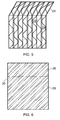
Figures 4 and5 , a fluid guiding member is provided to assist the second flow,Flow 2, in turning from the direction of theinlet header 10 to the direction of the fluid path through theheat exchanger plates 20 and/or from the direction of the fluid path through theheat exchanger plates 20 to the direction of theoutlet header 12. The fluid guiding member is provided by anangled portion 26 of eachheat exchanger plate 20 adjacent to the inlet and/oroutlet header angled portion 26 is angled with respect to the remainder of theheat exchanger plate 20 - The
heat exchanger plates 20 are provided with a series ofcorrugations 28 which run diagonally across theplates 20, i.e. at an oblique angle to the sides of theplate 20. Adjacentheat exchanger plates 20 are cross-corrugated such that theirrespective corrugations 28 run in opposite directions, crossing over one another at a point along their length. - The cross-corrugated configuration of the
heat exchanger plates 20 promotes turbulence and mixing within the flow, which improves heat transfer and thus improves the efficiency of theheat exchanger 6. - The formation of the
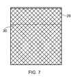
angled portion 26 would cause the orientation of thecorrugations 28 to deviate along their length when viewed from in front of theheat exchanger plates 20. To counteract this, the geometry of thecorrugations 26 is sheared such that, following the formation of theangled portion 26, peaks and troughs of thecorrugations 28 appear linear, as shown inFigure 6 . To shear the geometry of thecorrugations 28, points of thecorrugations 28 along aline 30 where theangled portion 26 meets the remainder of theheat exchanger plate 20 remain fixed, whereas other points of thecorrugations 28 are translated parallel to theline 30 by a distance proportional to their perpendicular distance from theline 30. -
Figure 7 shows a wire frame model of the front view of theheat exchanger plate 20 showing the effect on flow across thecorrugations 28. As can be seen, by shearing the geometry of thecorrugations 28, the 2D flow pattern is not affected by theangled portion 26. Shearing the geometry also prevents mechanical distortion by maintaining the pattern of contact points between peaks of adjacentheat exchanger plates 20. This method maintains the flow path on both sides of the heat exchanger (Flow 1 and Flow 2). -
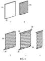
Figure 8 shows an embodiment of a method of constructing aheat exchanger plate 20. - Two
separate sheets 32 of material are used to form the heat exchange plate 20 (step 1 as shown inFigure 8 ).Corrugations 28 are formed in a surface of each of the two sheets 32 (step 2). Thecorrugations 28 are formed such that thecorrugations 28 of the twosheets 32 are parallel when the un-corrugated surfaces of the twosheets 32 are facing each other.Sections 34 of the sheets which are to become theangled portion 26 are then sheared by extruding thesheets 32 at an angle (step 3). - The angle at which the
sheets 32 are extruded is dependent on the desired angle of theangled portion 26 with respect to the remainder of theheat exchanger plate 20. Furthermore, the direction of shear depends on which way the angled portion is to be angled. For example, where theheat exchanger plate 20 forms a "Z" shape with the inlet at the top of the "Z" and the outlet at the bottom of the "Z", thesection 34 adjacent the inlet will be sheared in the opposite direction to thesection 34 adjacent the outlet. Conversely, where theheat exchanger plate 20 forms a "C" shape, thesection 34 adjacent the inlet and thesection 34 adjacent the outlet will be sheared in the same direction. - Subsequently, the two sheets are joined together (step 4) to form the
heat exchanger plate 20 using a suitable joining process, with the un-corrugated surfaces of the twosheets 32 facing one another. As a result of the sheets being arranged so that their un-corrugated surfaces face one another, the shearedsections 34 are angled in opposite directions. Consequently, thesheets 32 do not overlap inregions 36 at the sides of the shearedsections 34. Theregions 36 where thesheets 32 do not overlap are removed by trimming theheat exchanger plate 20 to the desired size (step 5). - Whilst the above steps describe some pertinent steps for construction of a suitable geometry, in reality, additional manufacturing steps would be required. The
heat exchanger plates 20 would need to be hollow and so an operation to hollow the resulting solid would be undertaken. Manufacturing methods would also typically involve treating the resulting geometry, for example by electroplating the solid produced by the process ofFigure 8 and/or by stamping and joining plates so that the resulting shape would be the surface of the solid resulting fromFigure 8 . -
Figure 9 provides a parameterisation which fully defines thecorrugations 28 of theheat exchanger plates 20. As shown in view AE, the corrugations have an amplitude (the difference in height between a peak 38 and a trough 40) of 1.3mm and a wavelength (the separation between adjacent peaks 38) of 2.86mm. The peak 38 andtroughs 40 have a radius of curvature of 0.286mm and are interconnected by angled sides. - As described previously, the corrugations of adjacent
heat exchanger plates 20 are arranged in a cross-corrugated manner, such that their peaks and troughs are perpendicular to one another, as shown in view AB. Furthermore, the distance between peaks 38 of the adjacentheat exchanger plates 20 is 2.6mm as shown in view AC. -
Figure 10 shows an external fluid guiding member which may be used to change the direction of the flow either independently or in combination with theangled portion 26 described previously. This external fluid guiding member comprises acurved plate 42 adjacent to the inlet and/or outlet side of each of theheat exchanger plates 20. Thecurved plate 42 is an elongate plate which is coupled to theheat exchanger plates 20 along their inlet and/or outlet side and is curved from the plane of theheat exchanger plates 20 towards the desired direction of flow. Thecurved plate 42 may have a constant thickness. - In
Figure 10 , thecurved plate 42 is located so as to change the direction of fluid flow at the outlet of the second flow,Flow 2. Furthermore, thecurved plate 42 is shown in combination with theangled portions 26 which are used to change the direction of fluid flow at the inlet and outlet of the first flow,Flow 1. Consequently, thecurved plate 42 is also profiled along the length of theheat exchanger plates 20 so that it conforms to the profile of theangled portions 26. -
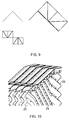
Figure 11 shows another external fluid guiding member which may be used to change the direction of the flow either independently or in combination with theangled portion 26 described previously. This external fluid guiding member comprises anaerofoil portion 44. Whereas thecurved plate 42 has a constant thickness, theaerofoil portion 44 tapers towards its end. Theaerofoil portion 44 has an upper surface 46 and a lower surface 48 which join at apoint 50. The upper surface 46 and lower surface 48 are corrugated with the peaks of the corrugations running in the direction of the bulk flow. - An
aerofoil portion 44 is located between the fluid paths of neighbouring pairs ofheat exchanger plates 20, such that the fluid from one pair ofheat exchanger plates 20 flows over the upper surface 46 and fluid from the other pair ofheat exchanger plates 20 passes over the lower surface 48. As shown inFigure 11 ,aerofoil portions 44 are located between alternate neighbouring pairs ofheat exchanger plates 20. - The pairs of
heat exchanger plates 20 terminate in aflat surface 52, which is located at a position where thecorrugations 28 of adjacentheat exchanger plates 20 are in phase. Theflat surface 52 has aninner edge 53 and anouter edge 55 defined by the pair ofheat exchanger plates 20. To form the upper surface 46 of theaerofoil portion 44, theouter edge 55 of theflat surface 52 is revolved about an axis positioned such that the surface of revolution is tangential to theouter edge 55 and at a radius chosen as a design parameter. Consequently, the upper surface 46 forms a continuous surface with theheat exchanger plate 20. Similarly, the lower surface 48 of theaerofoil portion 44 is formed by revolving theinner edge 53 of theflat surface 52 about a separate axis positioned such that the surface of revolution is tangential to theinner edge 53 and at a radius chosen as a design parameter. Again, this creates a continuous surface between theheat exchanger plate 20 and the lower surface 48. For the pairs ofheat exchanger plates 20 which do not have anaerofoil portion 44, theheat exchanger plates 20 terminate in theflat surface 52. - A 2D section of the flow path between two pairs of
heat exchanger plates 20 comprising anangled portion 26 is shown inFigure 12 . - An identical view is shown in
Figure 13 for two pairs ofheat exchanger plates 20 having both anangled portion 26 and anaerofoil portion 44. As shown, theaerofoil portions 44 have double circular arc aerofoil profile, however other profiles may be used. - By having
aerofoil portions 44 on both neighbouring pairs ofheat exchanger plates 20, the mean free passage area 56 (i.e. the size of a sphere that is able to pass through the geometry) is reduced in the region of the aerofoil portions. As the turning angle of theaerofoil portion 44 increases (i.e. a larger arc length) the free passage becomes more constricted. - As described with reference to
Figure 11 ,aerofoil portions 44 may be located between alternate neighbouring pairs ofheat exchanger plates 20, particularly where a larger turning angle is required. Consequently, the meanfree passage area 56 is increased, as shown inFigure 14 . A larger meanfree passage area 56 reduces clogging in theheat exchanger core 8 leading to increased heat transfer. - As an alternative, each neighbouring pair of
heat exchanger plates 20 may be provided with anaerofoil portion 44, however, theaerofoil portions 44 of adjacent neighbouring pairs of heat exchanger plates may be dissimilar i.e. they have different arc lengths. This configuration provides turning of the flow whilst maintaining a suitably large meanfree passage area 56, as shown inFigure 15 . -
Figure 16 shows the effect which theaerofoil portion 44 has on the flow through the heat exchanger. As shown, theaerofoil portion 44 turns the cross-corrugated flow in the plane of the bulk flow from the direction of thecorrugations 28 to the bulk flow direction at the junction between theangled portion 26 and theaerofoil portion 44. This turning process results in a loss of total pressure. However, the bulk velocity is lower in the region of theheat exchanger plates 20 than in the region of theaerofoil portion 44 and consequently lower losses are experienced. - As shown in
Figure 17 , the direction of the flow is changed by theangled portion 26 and subsequently by theaerofoil portion 44. This fluid guiding member configuration may be employed at both the inlet and outlet to the heat exchanger core. Therefore, as shown inFigure 18 , this configuration can be used to guide the flow from the direction of theinlet header 14 towards the plane of theheater exchanger plates 20 and also from this plane towards the direction of theoutlet header 16. The flow is preferably rotated by an inlet angle of approximately 30 degrees and by an exit angle of approximately 75 degrees. -
Figure 19 is a graph showing the distribution of flow within theheat exchanger core 8. The graph plots the velocity through each of theheat exchanger plates 20 from the firstshort side 10 to the secondshort side 12. - It is desirable to have a uniform distribution of flow through the
heat exchanger core 8 in order to maximise the efficiency of theheat exchanger 6. This idealised distribution is shown by the "Uniform" line. - The "HP000000" line shows the distribution for a
heat exchanger 6 without any fluid guiding means, whereas the "HP000075" line shows the distribution for aheat exchanger 6 with one or more of the fluid guiding members of the present invention which provide an exit angle of 75 degrees. - As can be seen, the flow within the heat exchanger without any fluid guiding means ("HP000000" line) has a larger velocity in the
heat exchanger plates 20 towards the firstshort side 10. This indicates that the majority of the flow passes through theseheat exchanger plates 20, thus reducing the efficiency of theheat exchanger 6. - In contrast, the "HP000075" line has a far more even distribution of flow within the
heat exchanger core 8 and thus more closely resembles the "Uniform" line. The fluid guiding members of the present invention therefore provide a moreefficient heat exchanger 6 with improved heat transfer properties. -
Figure 20 shows a plan view of an alternative configuration of the heat exchanger. Whilst this embodiment is described as being separate to that ofheat exchanger 6 offigure 2 for reasons of clarity, it will be appreciated that the view offigure 20 may also be considered representative ofFlow path 2 ofheat exchanger 6. Here, aheat exchanger 106 comprises aheat exchanger core 108 and inlet andoutlet headers heat exchanger core 108 has a firstshort side 110 and a secondshort side 112. Theheat exchanger core 108 comprises a plurality of heat exchanger plates 20 (not shown) which spaced between the firstshort side 110 and the secondshort side 112 and are oriented in a plane which runs between the inlet andoutlet headers - In the
heat exchanger 106 theheaders heat exchanger core 108 such that the flow path through the heat exchanger core follows a "Z" shaped path. Again, one or more of the fluid guiding members of the present invention may be used to guide the flow from the direction of theinlet header 114 towards the plane of theheat exchanger plates 20 and also from this plane towards the direction of theoutlet header 116. The flow is preferably rotated by an inlet angle of approximately 30 degrees and by an exit angle of approximately 75 degrees. -
Figure 21 is a graph showing the distribution of flow within theheat exchanger core 108. The graph plots the velocity through each of theheat exchanger plates 20 from the firstshort side 110 to the secondshort side 112. - As for
Figure 19 , the idealised distribution is shown by the "Uniform" line. The "LP_08_30_01_vy" line shows the distribution for aheat exchanger 106 with an inlet fluid guiding member which has an inlet angle of 30 degrees but without any fluid guiding means at the exit of theheat exchanger core 108. The "LP_08_75_01_00_3075000_vy" line shows the distribution for aheat exchanger 106 with one or more of the fluid guiding members of the present invention which provide an inlet angle of 30 degrees and an exit angle of 75 degrees. - As can be seen, the flow within the heat exchanger without any fluid guiding means at the exit of the heat exchanger core 108 ("LP_08_30_01_vy" line) has a larger velocity in the
heat exchanger plates 20 towards the secondshort side 112. This indicates that the majority of the flow passes through theseheat exchanger plates 20, thus reducing the efficiency of theheat exchanger 6. - In contrast, the "LP_08_75_01_00_3075000_vy" line has a far more even distribution of flow within the
heat exchanger core 108 and thus more closely resembles the "Uniform" line. The fluid guiding members of the present invention therefore provide a moreefficient heat exchanger 106 with improved heat transfer properties. - Although described with reference to a cross-corrugated heat exchanger, the present invention may find applications in other types of heat exchanger.
- The corrugations have been defined with reference to the parameterisation of
Figure 9 . However, the corrugations could alternatively have a sinusoidal, saw tooth or square wave type profile or any other type of profile. Furthermore, the corrugations could have a herringbone configuration or other configurations which are known to promote turbulence within the flow. - The heat exchanger of the present invention may be used as an intercooler in a primary gas path of a gas turbine engine. However, the heat exchanger could be used in any application, particularly where there are space constraints which result in the heat exchanger being installed at an angle.
- To avoid unnecessary duplication of effort and repetition of text in the specification, certain features are described in relation to only one or several aspects or embodiments of the invention. However, it is to be understood that, where it is technically possible, features described in relation to any aspect or embodiment of the invention may also be used with any other aspect or embodiment of the invention.
Claims (10)
- A heat exchanger (6) comprising:a heat exchanger core (8) comprising a plurality of corrugated heat exchanger plates (20);a fluid path through the heat exchanger core (8), the fluid path running between adjacent heat exchanger plates (20) and having an inlet (10) at one side of the heat exchanger plates (20) and an outlet (16) at an opposing side of the heat exchanger plates (20); anda fluid guiding member adjacent to the inlet and/or outlet side of the heat exchanger plate (20), the fluid guiding member comprising an angled portion (26) of each heat exchanger plate (20) which is angled with respect to the remainder of the heat exchanger plate (20) and being operable to change the direction of fluid flow,characterised in that: the geometry of the heat exchanger plates (20) is sheared such that the corrugations (28) are not distorted by the angled portion.
- A heat exchanger as claimed in claim 1, wherein the fluid guiding member changes the direction of fluid flow by approximately 30 degrees at the inlet of the fluid path and/or approximately 75 degrees at the outlet of the fluid path.
- A heat exchanger as claimed in claim 1, wherein the fluid guiding member comprises a curved plate adjacent to the inlet and/or outlet side of one or more of the heat exchanger plates.
- A heat exchanger as claimed in any preceding claim, wherein the fluid guiding member comprises an aerofoil portion which is located between the fluid paths of neighbouring pairs of heat exchanger plates.
- A heat exchanger as claimed in claim 4, wherein aerofoil portions are located between alternate neighbouring pairs of heat exchanger plates.
- A heat exchanger as claimed in claim 5, wherein aerofoil portions are located between neighbouring pairs of hear exchanger plates, and wherein the aerofoil portions of adjacent neighbouring pairs of heat exchanger plates are dissimilar.
- A heat exchanger as claimed in any preceding claim, wherein the fluid guiding member is integral with the heat exchanger plates.
- A gas turbine engine comprising a heat exchanger as claimed in any one of the preceding claims.
- A method of manufacturing a cross-corrugated heat exchanger plate (20) with an angled portion (26), the method comprising:providing two sheets of material;forming corrugations (28) at an oblique angle across a surface of each sheet;shearing the geometry of a portion of the sheets at the location of the angled portion (26); andjoining the two sheets together.
- A method as claimed in claim 9, wherein shearing the geometry comprises extruding the portion at an angle.
Applications Claiming Priority (2)
| Application Number | Priority Date | Filing Date | Title |
|---|---|---|---|
| GBGB1009701.2A GB201009701D0 (en) | 2010-06-10 | 2010-06-10 | A heat exchanger |
| PCT/EP2011/058376 WO2011154241A1 (en) | 2010-06-10 | 2011-05-23 | A heat exchanger |
Publications (2)
| Publication Number | Publication Date |
|---|---|
| EP2580552A1 EP2580552A1 (en) | 2013-04-17 |
| EP2580552B1 true EP2580552B1 (en) | 2016-10-05 |
Family
ID=42471431
Family Applications (1)
| Application Number | Title | Priority Date | Filing Date |
|---|---|---|---|
| EP11721039.3A Not-in-force EP2580552B1 (en) | 2010-06-10 | 2011-05-23 | A heat exchanger |
Country Status (4)
| Country | Link |
|---|---|
| US (1) | US9733026B2 (en) |
| EP (1) | EP2580552B1 (en) |
| GB (1) | GB201009701D0 (en) |
| WO (1) | WO2011154241A1 (en) |
Families Citing this family (4)
| Publication number | Priority date | Publication date | Assignee | Title |
|---|---|---|---|---|
| US10125684B2 (en) | 2015-12-29 | 2018-11-13 | Pratt & Whitney Canada Corp. | Surface cooler for aero engine |
| US11686530B2 (en) | 2018-03-16 | 2023-06-27 | Hamilton Sundstrand Corporation | Plate fin heat exchanger flexible manifold |
| JP2021134987A (en) * | 2020-02-27 | 2021-09-13 | 三菱重工業株式会社 | Heat exchange core and heat exchanger |
| US12584421B2 (en) | 2023-07-31 | 2026-03-24 | Rolls-Royce North American Technologies Inc. | Heat exchanger with inlet and outlet turning vanes for use in gas turbine engines |
Family Cites Families (15)
| Publication number | Priority date | Publication date | Assignee | Title |
|---|---|---|---|---|
| FR918616A (en) | 1945-08-27 | 1947-02-13 | Fluid guiding system for heat exchanger | |
| US2812165A (en) * | 1953-02-06 | 1957-11-05 | Air Preheater | Header units for plate type heat exchanger |
| US3291206A (en) * | 1965-09-13 | 1966-12-13 | Nicholson Terence Peter | Heat exchanger plate |
| US3968834A (en) * | 1975-02-07 | 1976-07-13 | Caterpillar Tractor Co. | Heat exchanger mounting for a turbine engine |
| US4913776A (en) * | 1988-08-15 | 1990-04-03 | The Air Preheater Company, Inc. | High efficiency folded plate heat exchanger |
| SE521382C2 (en) | 1998-09-01 | 2003-10-28 | Compact Plate Ab | Cross current type heat exchanger |
| EP1050618B1 (en) | 1999-04-08 | 2003-10-15 | BSH Bosch und Siemens Hausgeräte GmbH | Heat exchanger for laundry drier |
| GB0008897D0 (en) * | 2000-04-12 | 2000-05-31 | Cheiros Technology Ltd | Improvements relating to heat transfer |
| DE20121112U1 (en) | 2001-12-17 | 2003-04-24 | Autokühler GmbH & Co. KG, 34369 Hofgeismar | Manifold, particularly for motor vehicle heat exchanger, contains hollow chamber enclosed by wall, connecting aperture issuing into hollow chamber |
| DE20307881U1 (en) | 2003-05-21 | 2004-09-23 | Autokühler GmbH & Co. KG | Heat exchanger/charge cooler for a motor vehicle, has pipes to form a heat exchanger network, a collector with a receiver and flow-conducting elements with tapered thicknesses |
| DE102005038510A1 (en) | 2005-07-30 | 2007-02-01 | Dr.Ing.H.C. F. Porsche Ag | Ribs / tube block for a heat exchanger |
| JP2008151424A (en) | 2006-12-18 | 2008-07-03 | Ru Kikaku:Kk | Heat exchange element |
| US8541721B2 (en) * | 2008-12-01 | 2013-09-24 | Daniel Moskal | Wake generating solid elements for joule heating or infrared heating |
| DE102009022986A1 (en) * | 2009-05-28 | 2010-12-02 | Behr Gmbh & Co. Kg | Heat exchanger |
| DE102010015371A1 (en) * | 2010-04-19 | 2011-10-20 | Alexander Alles | Fluid media distributing device for use in honeycomb channels in e.g. heat exchanger, has adjacent plates including wave type profiles, and intermediate layer arranged in slot channels and including ribbed plates and contact points |
-
2010
- 2010-06-10 GB GBGB1009701.2A patent/GB201009701D0/en not_active Ceased
-
2011
- 2011-05-23 EP EP11721039.3A patent/EP2580552B1/en not_active Not-in-force
- 2011-05-23 US US13/695,998 patent/US9733026B2/en not_active Expired - Fee Related
- 2011-05-23 WO PCT/EP2011/058376 patent/WO2011154241A1/en not_active Ceased
Non-Patent Citations (1)
| Title |
|---|
| None * |
Also Published As
| Publication number | Publication date |
|---|---|
| GB201009701D0 (en) | 2010-07-21 |
| WO2011154241A1 (en) | 2011-12-15 |
| US20130048259A1 (en) | 2013-02-28 |
| US9733026B2 (en) | 2017-08-15 |
| EP2580552A1 (en) | 2013-04-17 |
Similar Documents
| Publication | Publication Date | Title |
|---|---|---|
| JP6496368B2 (en) | Heat exchanger with foam fins | |
| EP1653185B1 (en) | Heat exchanger | |
| EP2172728B1 (en) | A plate-fin type heat exchanger without sealing strip | |
| RU2413152C2 (en) | Heat exchanger from hollow flat sections | |
| EP2455695B1 (en) | Heat exchanger | |
| CN1833153B (en) | Heat exchanger and method for the production thereof | |
| US9851159B2 (en) | Curved cross-flow heat exchanger | |
| EP2410278B1 (en) | Plate-type heat exchanger and refrigerating air-conditioning device | |
| EP2455694A2 (en) | Heat exchanger | |
| US20090183862A1 (en) | Heat exchanger and related exchange module | |
| EP2607831A1 (en) | A heat exchanger | |
| US20150241142A1 (en) | Heat Exchanger Insert | |
| JP2007518958A (en) | Heat exchangers, especially oil / coolant coolers | |
| EP3789717B1 (en) | Heat exchanger vane with partial height airflow modifier | |
| EP2580552B1 (en) | A heat exchanger | |
| CN113834354B (en) | Three-dimensional uniform mixed flow heat exchanger core and heat exchanger | |
| CN103608639A (en) | Fin tube heat exchanger | |
| WO2012104383A1 (en) | A heat exchanger comprising a tubular element and a heat transfer element | |
| EP1373819B1 (en) | Plate heat exchanger and method for producing the same | |
| CN215832535U (en) | A kind of mixed rib heat exchanger core and heat exchanger | |
| CN106091757B (en) | A kind of package assembly and assemble method of full welding corrugated board cluster | |
| WO2019224767A1 (en) | Thermal exchanging device | |
| CN212673919U (en) | Micro-channel heat exchanger | |
| GB2183811A (en) | Rotary regenerative heat exchanger | |
| CN223154068U (en) | Novel plate heat exchanger of solid oxide fuel cell cogeneration system |
Legal Events
| Date | Code | Title | Description |
|---|---|---|---|
| PUAI | Public reference made under article 153(3) epc to a published international application that has entered the european phase |
Free format text: ORIGINAL CODE: 0009012 |
|
| 17P | Request for examination filed |
Effective date: 20121101 |
|
| AK | Designated contracting states |
Kind code of ref document: A1 Designated state(s): AL AT BE BG CH CY CZ DE DK EE ES FI FR GB GR HR HU IE IS IT LI LT LU LV MC MK MT NL NO PL PT RO RS SE SI SK SM TR |
|
| DAX | Request for extension of the european patent (deleted) | ||
| RAP1 | Party data changed (applicant data changed or rights of an application transferred) |
Owner name: ROLLS-ROYCE PLC |
|
| GRAP | Despatch of communication of intention to grant a patent |
Free format text: ORIGINAL CODE: EPIDOSNIGR1 |
|
| INTG | Intention to grant announced |
Effective date: 20160620 |
|
| GRAR | Information related to intention to grant a patent recorded |
Free format text: ORIGINAL CODE: EPIDOSNIGR71 |
|
| GRAS | Grant fee paid |
Free format text: ORIGINAL CODE: EPIDOSNIGR3 |
|
| INTC | Intention to grant announced (deleted) | ||
| GRAA | (expected) grant |
Free format text: ORIGINAL CODE: 0009210 |
|
| INTG | Intention to grant announced |
Effective date: 20160824 |
|
| AK | Designated contracting states |
Kind code of ref document: B1 Designated state(s): AL AT BE BG CH CY CZ DE DK EE ES FI FR GB GR HR HU IE IS IT LI LT LU LV MC MK MT NL NO PL PT RO RS SE SI SK SM TR |
|
| REG | Reference to a national code |
Ref country code: GB Ref legal event code: FG4D |
|
| REG | Reference to a national code |
Ref country code: CH Ref legal event code: EP |
|
| REG | Reference to a national code |
Ref country code: AT Ref legal event code: REF Ref document number: 835024 Country of ref document: AT Kind code of ref document: T Effective date: 20161015 |
|
| REG | Reference to a national code |
Ref country code: IE Ref legal event code: FG4D |
|
| REG | Reference to a national code |
Ref country code: DE Ref legal event code: R096 Ref document number: 602011030947 Country of ref document: DE |
|
| REG | Reference to a national code |
Ref country code: NL Ref legal event code: MP Effective date: 20161005 |
|
| REG | Reference to a national code |
Ref country code: LT Ref legal event code: MG4D |
|
| PG25 | Lapsed in a contracting state [announced via postgrant information from national office to epo] |
Ref country code: LV Free format text: LAPSE BECAUSE OF FAILURE TO SUBMIT A TRANSLATION OF THE DESCRIPTION OR TO PAY THE FEE WITHIN THE PRESCRIBED TIME-LIMIT Effective date: 20161005 |
|
| REG | Reference to a national code |
Ref country code: AT Ref legal event code: MK05 Ref document number: 835024 Country of ref document: AT Kind code of ref document: T Effective date: 20161005 |
|
| PG25 | Lapsed in a contracting state [announced via postgrant information from national office to epo] |
Ref country code: LT Free format text: LAPSE BECAUSE OF FAILURE TO SUBMIT A TRANSLATION OF THE DESCRIPTION OR TO PAY THE FEE WITHIN THE PRESCRIBED TIME-LIMIT Effective date: 20161005 Ref country code: GR Free format text: LAPSE BECAUSE OF FAILURE TO SUBMIT A TRANSLATION OF THE DESCRIPTION OR TO PAY THE FEE WITHIN THE PRESCRIBED TIME-LIMIT Effective date: 20170106 Ref country code: NO Free format text: LAPSE BECAUSE OF FAILURE TO SUBMIT A TRANSLATION OF THE DESCRIPTION OR TO PAY THE FEE WITHIN THE PRESCRIBED TIME-LIMIT Effective date: 20170105 Ref country code: SE Free format text: LAPSE BECAUSE OF FAILURE TO SUBMIT A TRANSLATION OF THE DESCRIPTION OR TO PAY THE FEE WITHIN THE PRESCRIBED TIME-LIMIT Effective date: 20161005 |
|
| REG | Reference to a national code |
Ref country code: FR Ref legal event code: PLFP Year of fee payment: 7 |
|
| PG25 | Lapsed in a contracting state [announced via postgrant information from national office to epo] |
Ref country code: HR Free format text: LAPSE BECAUSE OF FAILURE TO SUBMIT A TRANSLATION OF THE DESCRIPTION OR TO PAY THE FEE WITHIN THE PRESCRIBED TIME-LIMIT Effective date: 20161005 Ref country code: AT Free format text: LAPSE BECAUSE OF FAILURE TO SUBMIT A TRANSLATION OF THE DESCRIPTION OR TO PAY THE FEE WITHIN THE PRESCRIBED TIME-LIMIT Effective date: 20161005 Ref country code: PT Free format text: LAPSE BECAUSE OF FAILURE TO SUBMIT A TRANSLATION OF THE DESCRIPTION OR TO PAY THE FEE WITHIN THE PRESCRIBED TIME-LIMIT Effective date: 20170206 Ref country code: PL Free format text: LAPSE BECAUSE OF FAILURE TO SUBMIT A TRANSLATION OF THE DESCRIPTION OR TO PAY THE FEE WITHIN THE PRESCRIBED TIME-LIMIT Effective date: 20161005 Ref country code: RS Free format text: LAPSE BECAUSE OF FAILURE TO SUBMIT A TRANSLATION OF THE DESCRIPTION OR TO PAY THE FEE WITHIN THE PRESCRIBED TIME-LIMIT Effective date: 20161005 Ref country code: ES Free format text: LAPSE BECAUSE OF FAILURE TO SUBMIT A TRANSLATION OF THE DESCRIPTION OR TO PAY THE FEE WITHIN THE PRESCRIBED TIME-LIMIT Effective date: 20161005 Ref country code: BE Free format text: LAPSE BECAUSE OF FAILURE TO SUBMIT A TRANSLATION OF THE DESCRIPTION OR TO PAY THE FEE WITHIN THE PRESCRIBED TIME-LIMIT Effective date: 20161005 Ref country code: IS Free format text: LAPSE BECAUSE OF FAILURE TO SUBMIT A TRANSLATION OF THE DESCRIPTION OR TO PAY THE FEE WITHIN THE PRESCRIBED TIME-LIMIT Effective date: 20170205 Ref country code: FI Free format text: LAPSE BECAUSE OF FAILURE TO SUBMIT A TRANSLATION OF THE DESCRIPTION OR TO PAY THE FEE WITHIN THE PRESCRIBED TIME-LIMIT Effective date: 20161005 Ref country code: NL Free format text: LAPSE BECAUSE OF FAILURE TO SUBMIT A TRANSLATION OF THE DESCRIPTION OR TO PAY THE FEE WITHIN THE PRESCRIBED TIME-LIMIT Effective date: 20161005 |
|
| REG | Reference to a national code |
Ref country code: DE Ref legal event code: R097 Ref document number: 602011030947 Country of ref document: DE |
|
| PG25 | Lapsed in a contracting state [announced via postgrant information from national office to epo] |
Ref country code: RO Free format text: LAPSE BECAUSE OF FAILURE TO SUBMIT A TRANSLATION OF THE DESCRIPTION OR TO PAY THE FEE WITHIN THE PRESCRIBED TIME-LIMIT Effective date: 20161005 Ref country code: CZ Free format text: LAPSE BECAUSE OF FAILURE TO SUBMIT A TRANSLATION OF THE DESCRIPTION OR TO PAY THE FEE WITHIN THE PRESCRIBED TIME-LIMIT Effective date: 20161005 Ref country code: SK Free format text: LAPSE BECAUSE OF FAILURE TO SUBMIT A TRANSLATION OF THE DESCRIPTION OR TO PAY THE FEE WITHIN THE PRESCRIBED TIME-LIMIT Effective date: 20161005 Ref country code: DK Free format text: LAPSE BECAUSE OF FAILURE TO SUBMIT A TRANSLATION OF THE DESCRIPTION OR TO PAY THE FEE WITHIN THE PRESCRIBED TIME-LIMIT Effective date: 20161005 Ref country code: EE Free format text: LAPSE BECAUSE OF FAILURE TO SUBMIT A TRANSLATION OF THE DESCRIPTION OR TO PAY THE FEE WITHIN THE PRESCRIBED TIME-LIMIT Effective date: 20161005 |
|
| PLBE | No opposition filed within time limit |
Free format text: ORIGINAL CODE: 0009261 |
|
| STAA | Information on the status of an ep patent application or granted ep patent |
Free format text: STATUS: NO OPPOSITION FILED WITHIN TIME LIMIT |
|
| PG25 | Lapsed in a contracting state [announced via postgrant information from national office to epo] |
Ref country code: SM Free format text: LAPSE BECAUSE OF FAILURE TO SUBMIT A TRANSLATION OF THE DESCRIPTION OR TO PAY THE FEE WITHIN THE PRESCRIBED TIME-LIMIT Effective date: 20161005 Ref country code: BG Free format text: LAPSE BECAUSE OF FAILURE TO SUBMIT A TRANSLATION OF THE DESCRIPTION OR TO PAY THE FEE WITHIN THE PRESCRIBED TIME-LIMIT Effective date: 20170105 Ref country code: LU Free format text: LAPSE BECAUSE OF NON-PAYMENT OF DUE FEES Effective date: 20170531 Ref country code: IT Free format text: LAPSE BECAUSE OF FAILURE TO SUBMIT A TRANSLATION OF THE DESCRIPTION OR TO PAY THE FEE WITHIN THE PRESCRIBED TIME-LIMIT Effective date: 20161005 |
|
| 26N | No opposition filed |
Effective date: 20170706 |
|
| PG25 | Lapsed in a contracting state [announced via postgrant information from national office to epo] |
Ref country code: SI Free format text: LAPSE BECAUSE OF FAILURE TO SUBMIT A TRANSLATION OF THE DESCRIPTION OR TO PAY THE FEE WITHIN THE PRESCRIBED TIME-LIMIT Effective date: 20161005 |
|
| REG | Reference to a national code |
Ref country code: CH Ref legal event code: PL |
|
| PG25 | Lapsed in a contracting state [announced via postgrant information from national office to epo] |
Ref country code: MC Free format text: LAPSE BECAUSE OF FAILURE TO SUBMIT A TRANSLATION OF THE DESCRIPTION OR TO PAY THE FEE WITHIN THE PRESCRIBED TIME-LIMIT Effective date: 20161005 |
|
| REG | Reference to a national code |
Ref country code: IE Ref legal event code: MM4A |
|
| PG25 | Lapsed in a contracting state [announced via postgrant information from national office to epo] |
Ref country code: LI Free format text: LAPSE BECAUSE OF NON-PAYMENT OF DUE FEES Effective date: 20170531 Ref country code: CH Free format text: LAPSE BECAUSE OF NON-PAYMENT OF DUE FEES Effective date: 20170531 |
|
| PG25 | Lapsed in a contracting state [announced via postgrant information from national office to epo] |
Ref country code: LU Free format text: LAPSE BECAUSE OF NON-PAYMENT OF DUE FEES Effective date: 20170523 |
|
| PG25 | Lapsed in a contracting state [announced via postgrant information from national office to epo] |
Ref country code: IE Free format text: LAPSE BECAUSE OF NON-PAYMENT OF DUE FEES Effective date: 20170523 |
|
| REG | Reference to a national code |
Ref country code: FR Ref legal event code: PLFP Year of fee payment: 8 |
|
| PG25 | Lapsed in a contracting state [announced via postgrant information from national office to epo] |
Ref country code: MT Free format text: LAPSE BECAUSE OF NON-PAYMENT OF DUE FEES Effective date: 20170523 |
|
| PG25 | Lapsed in a contracting state [announced via postgrant information from national office to epo] |
Ref country code: HU Free format text: LAPSE BECAUSE OF FAILURE TO SUBMIT A TRANSLATION OF THE DESCRIPTION OR TO PAY THE FEE WITHIN THE PRESCRIBED TIME-LIMIT; INVALID AB INITIO Effective date: 20110523 |
|
| PGFP | Annual fee paid to national office [announced via postgrant information from national office to epo] |
Ref country code: DE Payment date: 20190530 Year of fee payment: 9 |
|
| PGFP | Annual fee paid to national office [announced via postgrant information from national office to epo] |
Ref country code: FR Payment date: 20190527 Year of fee payment: 9 |
|
| PG25 | Lapsed in a contracting state [announced via postgrant information from national office to epo] |
Ref country code: CY Free format text: LAPSE BECAUSE OF NON-PAYMENT OF DUE FEES Effective date: 20161005 |
|
| PGFP | Annual fee paid to national office [announced via postgrant information from national office to epo] |
Ref country code: GB Payment date: 20190528 Year of fee payment: 9 |
|
| PG25 | Lapsed in a contracting state [announced via postgrant information from national office to epo] |
Ref country code: MK Free format text: LAPSE BECAUSE OF FAILURE TO SUBMIT A TRANSLATION OF THE DESCRIPTION OR TO PAY THE FEE WITHIN THE PRESCRIBED TIME-LIMIT Effective date: 20161005 |
|
| PG25 | Lapsed in a contracting state [announced via postgrant information from national office to epo] |
Ref country code: TR Free format text: LAPSE BECAUSE OF FAILURE TO SUBMIT A TRANSLATION OF THE DESCRIPTION OR TO PAY THE FEE WITHIN THE PRESCRIBED TIME-LIMIT Effective date: 20161005 |
|
| PG25 | Lapsed in a contracting state [announced via postgrant information from national office to epo] |
Ref country code: AL Free format text: LAPSE BECAUSE OF FAILURE TO SUBMIT A TRANSLATION OF THE DESCRIPTION OR TO PAY THE FEE WITHIN THE PRESCRIBED TIME-LIMIT Effective date: 20161005 |
|
| REG | Reference to a national code |
Ref country code: DE Ref legal event code: R119 Ref document number: 602011030947 Country of ref document: DE |
|
| GBPC | Gb: european patent ceased through non-payment of renewal fee |
Effective date: 20200523 |
|
| PG25 | Lapsed in a contracting state [announced via postgrant information from national office to epo] |
Ref country code: FR Free format text: LAPSE BECAUSE OF NON-PAYMENT OF DUE FEES Effective date: 20200531 Ref country code: GB Free format text: LAPSE BECAUSE OF NON-PAYMENT OF DUE FEES Effective date: 20200523 |
|
| PG25 | Lapsed in a contracting state [announced via postgrant information from national office to epo] |
Ref country code: DE Free format text: LAPSE BECAUSE OF NON-PAYMENT OF DUE FEES Effective date: 20201201 |