EP2579580A1 - Solid-state imaging device - Google Patents
Solid-state imaging device Download PDFInfo
- Publication number
- EP2579580A1 EP2579580A1 EP11786777.0A EP11786777A EP2579580A1 EP 2579580 A1 EP2579580 A1 EP 2579580A1 EP 11786777 A EP11786777 A EP 11786777A EP 2579580 A1 EP2579580 A1 EP 2579580A1
- Authority
- EP
- European Patent Office
- Prior art keywords
- row
- section
- data
- selecting section
- row selecting
- Prior art date
- Legal status (The legal status is an assumption and is not a legal conclusion. Google has not performed a legal analysis and makes no representation as to the accuracy of the status listed.)
- Granted
Links
- 238000003384 imaging method Methods 0.000 title claims abstract description 105
- 238000007599 discharging Methods 0.000 claims description 23
- 230000003287 optical effect Effects 0.000 description 43
- 238000010586 diagram Methods 0.000 description 38
- 238000009825 accumulation Methods 0.000 description 5
- 238000009792 diffusion process Methods 0.000 description 5
- 238000006243 chemical reaction Methods 0.000 description 3
- 238000005070 sampling Methods 0.000 description 2
- 230000000694 effects Effects 0.000 description 1
Images


Classifications
-
- H—ELECTRICITY
- H04—ELECTRIC COMMUNICATION TECHNIQUE
- H04N—PICTORIAL COMMUNICATION, e.g. TELEVISION
- H04N25/00—Circuitry of solid-state image sensors [SSIS]; Control thereof
- H04N25/70—SSIS architectures; Circuits associated therewith
- H04N25/76—Addressed sensors, e.g. MOS or CMOS sensors
- H04N25/767—Horizontal readout lines, multiplexers or registers
-
- H—ELECTRICITY
- H04—ELECTRIC COMMUNICATION TECHNIQUE
- H04B—TRANSMISSION
- H04B10/00—Transmission systems employing electromagnetic waves other than radio-waves, e.g. infrared, visible or ultraviolet light, or employing corpuscular radiation, e.g. quantum communication
- H04B10/11—Arrangements specific to free-space transmission, i.e. transmission through air or vacuum
-
- H—ELECTRICITY
- H04—ELECTRIC COMMUNICATION TECHNIQUE
- H04N—PICTORIAL COMMUNICATION, e.g. TELEVISION
- H04N25/00—Circuitry of solid-state image sensors [SSIS]; Control thereof
- H04N25/40—Extracting pixel data from image sensors by controlling scanning circuits, e.g. by modifying the number of pixels sampled or to be sampled
- H04N25/42—Extracting pixel data from image sensors by controlling scanning circuits, e.g. by modifying the number of pixels sampled or to be sampled by switching between different modes of operation using different resolutions or aspect ratios, e.g. switching between interlaced and non-interlaced mode
-
- H—ELECTRICITY
- H04—ELECTRIC COMMUNICATION TECHNIQUE
- H04N—PICTORIAL COMMUNICATION, e.g. TELEVISION
- H04N25/00—Circuitry of solid-state image sensors [SSIS]; Control thereof
- H04N25/40—Extracting pixel data from image sensors by controlling scanning circuits, e.g. by modifying the number of pixels sampled or to be sampled
- H04N25/44—Extracting pixel data from image sensors by controlling scanning circuits, e.g. by modifying the number of pixels sampled or to be sampled by partially reading an SSIS array
- H04N25/443—Extracting pixel data from image sensors by controlling scanning circuits, e.g. by modifying the number of pixels sampled or to be sampled by partially reading an SSIS array by reading pixels from selected 2D regions of the array, e.g. for windowing or digital zooming
Definitions
- the present invention relates to a solid-state imaging device.
- a solid-state imaging device includes a light receiving section where M ⁇ N pixel units P 1,1 to P M,N each including a photodiode and a charge accumulating section are two-dimensionally arrayed in M rows and N columns, a row selecting section that causes each pixel unit P m,n in a light receiving section to accumulate charge generated in the photodiode during a given period in its charge accumulating section, and to output data corresponding to an amount of the charge accumulated in each pixel unit P m,n in every row, and a readout section for which the data output from each pixel unit P m,n in the light receiving section is input and from which data corresponding to an amount of charge generated in the photodiode of each pixel unit P m,n is output. Also, in some cases, the solid-state imaging device further includes an AD conversion section that analog/digital-converts the data output from the readout section to output a digital value.
- Such a solid-state imaging device is capable of detecting an intensity of light reaching each pixel unit P m,n in its light receiving section, to perform imaging. Further, in recent years, not only imaging, but an attempt has been made to perform optical communication by using such a solid-state imaging device.
- a solid-state imaging device of the invention disclosed in Patent Literature 1 has a plurality of means for reading out data from each pixel unit, and is capable of performing imaging by reading out data by every pixel unit with the first readout means among those. Further, the solid-state imaging device adds current signals generated from photodiodes of specific one pixel unit, or two or more pixel units to output the signal with the second readout means, so that the solid-state imaging device is capable of receiving an optical signal.
- Patent Literature 1 Japanese Patent No. 3995959
- a data readout speed by the first readout means is, for example, several tens of fps (frame per second).
- a data readout speed by the second readout means is, for example, several tens of kbps (kilo bit per second).
- the present inventors have found that the following problems occur in such a solid-state imaging device that performs imaging and optical communication.
- the solid-state imaging device of the invention disclosed in Patent Literature 1 is intended to be used for a case where an optical signal source may be moved.
- the position of the optical signal source is specified on the basis of image data read out by the first readout means, and data from the pixel units at the specified position in the image are read out as communication data by the second readout means.
- the communication data initially read out by the second readout means immediately after the time t correspond to an amount of the charge finally accumulated over a long period immediately before the time t
- the communication data may be wrong values in some cases.
- the solid-state imaging device is not able to accurately receive an optical signal from the optical signal source.
- An object of the present invention is to provide a solid-state imaging device for optical communication, which is capable of accurately receiving an optical signal from the optical signal source even in a case where the position of an optical signal source is tracked.
- a solid-state imaging device includes (1) a light receiving section where M ⁇ N pixel units P 1,1 to P M,N each including a photodiode that generates charge of an amount according to an incident light amount, a charge accumulating section in which the charge is accumulated, a first switch for outputting data corresponding to an accumulated charge amount in the charge accumulating section, and a second switch for outputting data corresponding to the accumulated charge amount in the charge accumulating section are two-dimensionally arrayed in M rows and N columns, (2) a first row selecting section which selects any m1-th row in the light receiving section, and outputs a control signal to each pixel unit P m1,n of the m1-th row, thereby discharging a junction capacitance section of the photodiode, accumulating the charge generated in the photodiode in the charge accumulating section, and outputting data corresponding to the accumulated charge amount in the charge accumulating section to a readout signal line L1 n by
- the solid-state imaging device selects any m3-th row in the light receiving section, and outputs a control signal to each pixel unit P m3,n of the m3-th row, thereby discharging a junction capacitance section of the photodiode, and the first row selecting section and the first readout section, and the second row selecting section and the second readout section operate in parallel with each other (provided that M and N are integers not less than 2, m1 and m2 are integers not less than 1 and not more than M, which are different from each other, m3 is an integer not less than 1 and not more than M, and n is an integer not less than 1 and not more than N).
- any m1-th row in the light receiving section is selected by the first row selecting section, and in each pixel unit P m1,n of the m1-th row, the junction capacitance section of the photodiode is discharged, the charge generated in the photodiode is accumulated in the charge accumulating section, and the data corresponding to the accumulated charge amount in the charge accumulating section is output to the readout signal line L1 n by closing the first switch.
- each readout section which is connected to each readout signal L1 n, data output from each pixel unit P m1,n of the m1-th row in the light receiving section selected by the first row selecting section to the readout signal line L1 n is input thereto, and data corresponding to the amount of charge generated in the photodiode of each pixel unit P m1,n of the m1-th row is output.
- any m2-th row in the light receiving section is selected by the second row selecting section, and in each pixel unit P m2,n of the m2-th row, the junction capacitance section of the photodiode is discharged, the charge generated in the photodiode is accumulated in the charge accumulating section, and the data corresponding to the accumulated charge amount in the charge accumulating section is output to a readout signal line L2 n by closing the second switch.
- Rows different from each other in the light receiving section are selected by the first row selecting section and the second row selecting section. Then, the first row selecting section and the first readout section, and the second row selecting section and the second readout section operate in parallel with each other. Thereby, for example, image data by the first row selecting section and the first readout section is obtained, and communication data by the second row selecting section and the second readout section is obtained.
- any m3-th row in the light receiving section is selected, and in each pixel unit P m3,n of the m3-th row, the junction capacitance section of the photodiode is discharged.
- the first row selecting section or the second row selecting section select any m3-th row different from the m1-th row and the m2-th row in the light receiving section, and outputs a control signal to each pixel unit P m3,n of the m3-th row, thereby discharging the junction capacitance section of the photodiode.
- m1, m2, and m3 are integers not less than 1 and not more than M, which are different from each other.
- any m3-th row different from the m1-th row and the m2-th row in the light receiving section is selected by the first row selecting section or the second row selecting section, and in each pixel unit P m3,n of the m3-th row, the junction capacitance section of the photodiode is discharged.
- the solid-state imaging device further include switching means for switching between the first row selecting section and the second row selecting section, to determine any one of the first row selecting section and the second row selecting section as a row selecting section which outputs a control signal to each pixel unit P m3,n of the m3-th row in the light receiving section, thereby discharging the junction capacitance section of the photodiode.
- the first row selecting section include M latch circuits, and when data held in an m1-th latch circuit among the M latch circuits is a significant value, the first row selecting section output a control signal to each pixel unit P m1,n of the m1-th row
- the second row selecting section include M latch circuits, and when data held in an m2-th latch circuit among the M latch circuits is a significant value, the second row selecting section output a control signal to each pixel unit P m2,n of the m2-th row
- any row selecting section of the first row selecting section and the second row selecting section output a control signal to each pixel unit P m3,n of the m3-th row when data held in an m3-th latch circuit among the M latch circuits of the other row selecting section is an insignificant value.
- the M latch circuits of each of the first row selecting section and the second row selecting section be cascade-connected in order of the rows, to compose a shift register, and M-bit data be serial-input to a latch circuit at the first stage in the shift register, to cause each latch circuit to hold data.
- the first row selecting section sequentially output the control signals at a constant time interval to a plurality of rows corresponding to latch circuits with holding data of significant values among the M latch circuits included in the first row selecting section
- the second row selecting section sequentially output the control signals at a constant time interval to a plurality of rows corresponding to latch circuits with holding data of significant values among the M latch circuits included in the second row selecting section.
- the solid-state imaging device further include a third row selecting section which selects any m3-th row in the light receiving section, and outputs a control signal to each pixel unit P m3,n of the m3-th row, thereby discharging a junction capacitance section of the photodiode.
- a third row selecting section which selects any m3-th row in the light receiving section, and outputs a control signal to each pixel unit P m3,n of the m3-th row, thereby discharging a junction capacitance section of the photodiode.
- the first row selecting section include M latch circuits, and when data held in an m1-th latch circuit among the M latch circuits is a significant value, the first row selecting section output a control signal to each pixel unit P m1,n of the m1-th row
- the second row selecting section include M latch circuits, and when data held in an m2-th latch circuit among the M latch circuits is a significant value, the second row selecting section output a control signal to each pixel unit P m2,n of the m2-th row
- the third row selecting section include M latch circuits, and when data held in an m3-th latch circuit among the M latch circuits is a significant value, the third row selecting section output a control signal to each pixel unit P m3,n of the m3-th row.
- the M latch circuits of each of the first row selecting section, the second row selecting section, and the third row selecting section be cascade-connected in order of the rows, to compose a shift register, and M-bit data be serial-input to a latch circuit at the first stage in the shift register, to cause each latch circuit to hold data.
- the first row selecting section sequentially output the control signals at a constant time interval to a plurality of rows corresponding to latch circuits with holding data of significant values among the M latch circuits included in the first row selecting section
- the second row selecting section sequentially output the control signals at a constant time interval to a plurality of rows corresponding to latch circuits with holding data of significant values among the M latch circuits included in the second row selecting section.
- the solid-state imaging device of the present invention is capable of accurately receiving an optical signal from the optical signal source even in a case where the position of an optical signal source is tracked.
- Fig. 1 is a diagram showing a schematic configuration of a solid-state imaging device 1 according to a first embodiment.
- the solid-state imaging device 1 shown in this figure includes a light receiving section 10, a first row selecting section 20, a second row selecting section 30, a first readout section 40, a second readout section 50, and a control section 60.
- the light receiving section 10 includes M ⁇ N pixel units P 1,1 to P M,N .
- the M ⁇ N pixel units P 1,1 to P M,N have a common configuration, and these are two-dimensionally arrayed in M rows and N columns.
- Each pixel unit P m,n is located in the m-th row and the n-th column.
- M and N are integers not less than 2
- m is an integer not less than 1 and not more than M
- n is an integer not less than 1 and not more than N.
- Each pixel unit P m,n has a photodiode that generates charge of an amount according to an incident light amount and a charge accumulating section in which the charge is accumulated.
- Each pixel unit P m,n is capable of discharging a junction capacitance section of the photodiode, accumulating charge generated in the photodiode in its charge accumulating section, and outputting data corresponding to the accumulated charge amount in the charge accumulating section to a readout signal line L1 n or a readout signal line L2 n on the basis of various control signals received via control signal lines from the first row selecting section 20 or the second row selecting section 30.
- the first row selecting section 20 selects any m1-th row in the light receiving section 10, and outputs a control signal to each pixel unit P m1,n of the m1-th row, thereby discharging a junction capacitance section of the photodiode, accumulating the charge generated in the photodiode in the charge accumulating section, and outputting data corresponding to the accumulated charge amount in the charge accumulating section to the readout signal line L1 n .
- the second row selecting section 30 selects any m2-th row in the light receiving section 10, and outputs a control signal to each pixel unit P m2,n of the m2-th row, thereby discharging a junction capacitance section of the photodiode, accumulating the charge generated in the photodiode in the charge accumulating section, and outputting data corresponding to the accumulated charge amount in the charge accumulating section to the readout signal line L2 n .
- the first row selecting section 20 selects any m3-th row in the light receiving section 10, and outputs a control signal to each pixel unit P m3,n of the m3-th row, thereby discharging a junction capacitance section of the photodiode, and accumulating the charge generated in the photodiode in the charge accumulating section.
- m1, m2, and m3 are integers not less than 1 and not more than M, which are different from each other.
- the first row selecting section 20 and the second row selecting section 30 select rows different from each other in the light receiving section 10.
- the number of rows selected by each of the first row selecting section 20 and the second row selecting section 30 is arbitrary. However, the output of data is sequentially carried out with respect to every single row.
- the first readout section 40 is connected to N readout signal lines L1 1 to L1 N , and data output from each pixel unit P m1,n of the m1-th row in the light receiving section 10 selected by the first row selecting section 20 to the readout signal line L1 n is input thereto, and data corresponding to an amount of charge generated in the photodiode of each pixel unit P m1,n of the m1-th row is output therefrom.
- the second readout section 50 is connected to N readout signal lines L2 1 to L2 N , data output from each pixel unit P m2,n of the m2-th row in the light receiving section 10 selected by the second row selecting section 30 to the readout signal line L2 n is input thereto, and data corresponding to an amount of charge generated in the photodiode of each pixel unit P m2,n of the m2-th row is output therefrom.
- the control section 60 controls respective operations of the first row selecting section 20, the second row selecting section 30, the first readout section 40, and the second readout section 50, to control the entire operation of the solid-state imaging device 1.
- the first row selecting section 20 and the first readout section 40, the second row selecting section 30 and the second readout section 50 are capable of operating in parallel with each other under the control of the control section 60.
- Fig. 2 is a diagram showing configurations of the first readout section 40 and the second readout section 50 of the solid-state imaging device 1 according to the first embodiment.
- the pixel unit P m,n of the m-th row and the n-th column is shown as a representative of the M ⁇ N pixel units P 1,1 to P M,N in the light receiving section 10. Further, constitutional elements relating to the pixel unit P m,n are shown in each of the first readout section 40 and the second readout section 50.
- the first readout section 40 includes N holding sections 41 1 to 41 N , a first column selecting section 42, and a difference arithmetic section 43.
- the N holding sections 41 1 to 41 N have a common configuration.
- Each holding section 41 n is connected to M pixel units P 1,n to P M,n of the n-th column in the light receiving section 10 via the readout signal line L1 n , and allows data output from the pixel unit P m1,n of the m1-th row selected by the first row selecting section 20 to the readout signal line L1 n to be input thereto, to hold the data, and is capable of outputting the held data.
- Each holding section 41 n preferably allows data of signal components superimposed with noise components to be input thereto, to hold the data, and for allowing data of only noise components to be input thereto, to hold the data.
- the N holding sections 41 1 to 41 N are capable of sampling data at a same timing on the basis of various control signals received from the first column selecting section 42, to hold the sampled data, and sequentially output the held data.
- the difference arithmetic section 43 allows the data sequentially output from the respective N holding sections 41 1 to 41 N to be input thereto, and subtracts the data of only noise components from the data of signal components superimposed with noise components, to output data corresponding to the signal components.
- the difference arithmetic section 43 may output the data corresponding to the signal components as analog data, or may have an AD conversion function to output digital data.
- the first readout section 40 is capable of outputting data corresponding to an amount of charge generated in the photodiode of each pixel unit P m1,n of the m1-th row.
- the second readout section 50 includes N holding sections 51 1 to 51 N , a second column selecting section 52, and a difference arithmetic section 53.
- the N holding sections 51 1 to 51 N have a common configuration.
- Each holding section 51 n is connected to M pixel units P 1,n to P M,n of the n-th column in the light receiving section 10 via the readout signal line L2 n , and allows data output from the pixel unit P m2,n of the m2-th row selected by the second row selecting section 20 to the readout signal line L2 n to be input thereto, to hold the data, and is capable of outputting the held data.
- Each holding section 51 n preferably allows data of signal components superimposed with noise components to be input thereto, to hold the data, and for allowing data of only noise components to be input thereto, to hold the data.
- the N holding sections 51 1 to 51 N are capable of sampling data at a same timing on the basis of various control signals received from the second column selecting section 52, to hold the sampled data, and sequentially output the held data.
- the difference arithmetic section 53 allows the data sequentially output from the respective N holding sections 51 1 to 51 N to be input thereto, and subtracts the data of only noise components from the data of signal components superimposed with noise components, to output data corresponding to the signal components.
- the difference arithmetic section 53 may output the data corresponding to the signal components as analog data, or may have an AD conversion function to output digital data.
- the second readout section 50 is capable of outputting data corresponding to an amount of charge generated in the photodiode of each pixel unit P m2,n of the m2-th row.
- Fig. 3 is a diagram showing circuit configurations of the pixel unit P m,n and the holding section 41 n of the solid-state imaging device 1 according to the first embodiment.
- the pixel unit P m,n of the m-th row and the n-th column is shown as a representative of the M ⁇ N pixel units P 1,1 to P M,N in the light receiving section 10.
- the holding section 41 n relating to the pixel unit P m,n is shown in the first readout section 40.
- the configuration of the holding section 51 n is the same as the configuration of the holding section 41 n .
- Each pixel unit P m,n is of the APS (Active Pixel Sensor) type, that includes a photodiode PD and 6 MOS transistors T1, T2, T3, T4 1 , T4 2 , and T5.
- the transistor T1, the transistor T2, and the photodiode PD are sequentially connected in series, and a reference voltage is input to the drain terminal of the transistor T1, and the anode terminal of the photodiode PD is grounded.
- the connection point between the transistor T1 and the transistor T2 is connected to the gate terminal of the transistor T3 via the transistor T5.
- a reference voltage is input to the drain terminal of the transistor T3.
- the source terminal of the transistor T3 is connected to the respective drain terminals of the transistors T4 1 and T4 2 .
- the source terminal of the transistor T4 1 of each pixel unit P m,n is connected to the readout signal line L1 n .
- the source terminal of the transistor T4 2 of each pixel unit P m,n is connected to the readout signal line L2 n .
- a constant current source is connected to the readout signal line L1 n and the readout signal line L2 n , respectively.
- the gate terminal of the transistor T2 for transfer in each pixel unit P m,n is connected to a control signal line LT m , and a Trans(m) signal output from the first row selecting section 20 or the second row selecting section 30 is input thereto.
- the gate terminal of the transistor T1 for reset in each pixel unit P m,n is connected to a control signal line LR m , and a Reset(m) signal output from the first row selecting section 20 or the second row selecting section 30 is input thereto.
- the gate terminal of the transistor T5 for hold in each pixel unit P m,n is connected to a control signal line LH m , and a Hold(m) signal output from the first row selecting section 20 or the second row selecting section 30 is input thereto.
- the gate terminal of the transistor T4 1 for output selection in each pixel unit P m,n is connected to a control signal line LA1 m , and an Address1(m) signal output from the first row selecting section 20 is input thereto.
- the gate terminal of the transistor T4 2 for output selection in each pixel unit P m,n is connected to a control signal line LA2 m , and an Address2(m) signal output from the second row selecting section 30 is input thereto.
- These control signals (a Reset(m) signal, a Trans(m) signal, a Hold(m) signal, an Address1(m) signal, and an Address2(m) signal) are input in common to the N pixel units P m,1 to P m,N of the m-th row.
- the control signal line LT m , the control signal line LR m , and the control signal line LH m are provided to every row, and the control signals (a Reset(m) signal, a Trans(m) signal, a Hold(m) signal) giving instructions for discharge from each of the junction capacitance section of the photodiode PD in each pixel unit P m,n of the m-th row and the charge accumulating section, and for charge accumulation by the charge accumulating section are transmitted therethrough.
- the Reset(m) signal is a logical disjunction of a Reset1(m) signal output from the first row selecting section 20 and a Reset2(m) signal output from the second row selecting section 30.
- the Trans(m) signal is a logical disjunction of a Trans1(m) signal output from the first row selecting section 20 and a Trans2(m) signal output from the second row selecting section 30.
- the Hold(m) signal is a logical disjunction of a Hold1(m) signal output from the first row selecting section 20 and a Hold2(m) signal output from the second row selecting section 30.
- the control signal line LA1 m and the control signal line LA2 m are provided to every row, and the control signals (an Address1(m) signal, an Address2(m) signal) for giving instructions for data output to the readout signal line L1 n or the readout signal line L2 n in each pixel unit P m,n of the m-th row are transmitted therethrough.
- Each control signal line LA1 m is connected to the first row selecting section 20.
- Each control signal line LA2 m is connected to the second row selecting section 30.
- the Address1(m) signal and the Address2(m) signal are not raised to a high level simultaneously, and the transistor T4 1 and the transistor T4 2 do not move into an ON state simultaneously.
- the junction capacitance section of the photodiode PD is discharged, and further, a diffusion region (the charge accumulating section) connected to the gate terminal of the transistor T3 is discharged.
- the Trans(m) signal is at a low level, the charge generated in the photodiode PD is accumulated in the junction capacitance section.
- the Reset(m) signal When the Reset(m) signal is at a low level and the Trans(m) signal and the Hold(m) signal are at a high level, the charge accumulated in the junction capacitance section of the photodiode PD is transferred to the diffusion region (the charge accumulating section) connected to the gate terminal of the transistor T3 to be accumulated therein.
- the Address1(m) signal When the Address1(m) signal is at a high level, data (data of signal components superimposed with noise components) corresponding to an amount of the charge accumulated in the diffusion region (the charge accumulating section) connected to the gate terminal of the transistor T3 is output to the readout signal line L1 n via the transistor T4 1 , to be input to the holding section 41 n of the first readout section 40. That is, the transistor T4 1 operates as a first switch for outputting data corresponding to an accumulated charge amount in the charge accumulating section to the readout signal line L1 n . In addition, when the charge accumulating section is in a state of discharge, data of only noise components is output to the readout signal line L1 n via the transistor T4 1 .
- Each holding section 41 n includes two capacitive elements C 1 and C 2 , and four switches SW 11 , SW 12 , SW 2 , and SW 22 .
- the switch SW 11 and the switch SW 12 are connected in series to be provided between the readout signal line L1 n and a wiring Hline_s1, and one terminal of the capacitive element C 1 is connected to the connection point between the switch SW 11 and the switch SW 12 , and the other terminal of the capacitive element C 1 is grounded.
- the switch SW 21 , and the switch SW 22 are connected in series to be provided between the readout signal line L1 n and a wiring Hline_n1, and one terminal of the capacitive element C 2 is connected to the connection point between the switch SW 21 and the switch SW 22 , and the other terminal of the capacitive element C 2 is grounded.
- the switch SW 11 opens and closes according to a level of a set_s1 signal supplied from the first column selecting section 42.
- the switch SW 21 opens and closes according to a level of a set_n1 signal supplied from the first column selecting section 42.
- the set_s1 signal and the set_n1 signal are input in common to the N holding sections 41 1 to 41 N .
- the switches SW 12 and SW 22 open and close according to a level of an hshift1(n) signal supplied from the first column selecting section 42.
- the switch SW 12 is closed to output the voltage value out_s1(n) held by the capacitive element C 1 to the wiring Hline_s1
- the switch SW 22 is closed to output the voltage value out_n1(n) held by the capacitive element C 2 to the wiring Hline_n1.
- a difference between these voltage value out_s1(n) and voltage value out_n1(n) represents a voltage value corresponding to an amount of charge generated in the photodiode PD of the pixel unit P m,n .
- Fig. 4 is a diagram showing a circuit configuration of the difference arithmetic section 43 of the solid-state imaging device 1 according to the first embodiment.
- the configuration of the difference arithmetic section 53 is the same as the configuration of the difference arithmetic section 43.
- the difference arithmetic section 43 includes amplifiers A 1 to A 3 , switches SW 1 and SW 2 , and resistors R 1 to R 4 .
- the inverting input terminal of the amplifier A 3 is connected to the output terminal of the buffer amplifier A 1 via the resistor R 1 , and is connected to its own output terminal via the resistor R 3 .
- the non-inverting input terminal of the amplifier A 3 is connected to the output terminal of the buffer amplifier A 2 via the resistor R 2 , and is connected to a grounding potential via the resistor R 4 .
- the input terminal of the buffer amplifier A 1 is connected to the N holding sections 41 1 to 41 N via the wiring Hline_s1, and is connected to a grounding potential via the switch SW 1 .
- the input terminal of the buffer amplifier A 2 is connected to the N holding sections 41 1 to 41 N via the wiring Hline_n1, and is connected to a grounding potential via the switch SW 2 .
- the switches SW 1 and SW 2 in the difference arithmetic section 43 are controlled by an hresetl signal supplied from the first column selecting section 42 to carry out an opening and closing operation.
- the switch SW 1 When the switch SW 1 is closed, the voltage value input to the input terminal of the buffer amplifier A 1 is reset.
- the switch SW 2 is closed, the voltage value input to the input terminal of the buffer amplifier A 2 is reset.
- the switches SW 1 and SW 2 are open, the voltage values out_s1(n) and out_n1(n) output to the wirings Hline_s1 and Hline_n1 from any holding section 41 n among the N holding sections 41 1 to 41 N are input to the input terminals of the buffer amplifiers A 1 and A 2 .
- a voltage value output from the output terminal of the difference arithmetic section 43 represents a difference between the voltage values respectively input via the wiring Hline_s1 and the wiring Hline_n1, that is the value from which noise components are eliminated.
- Fig. 5 is a diagram showing configurations of the first row selecting section 20 and the second row selecting section 30 of the solid-state imaging device 1 according to the first embodiment.
- the first row selecting section 20 includes M control signal generating circuits 21 1 to 21 M composing a first shift register, and M latch circuits 22 1 to 22 M composing a second shift register.
- the second row selecting section 30 includes M control signal generating circuits 31 1 to 31 M composing a first shift register, and M latch circuits 32 1 to 32 M composing a second shift register.
- the respective M control signal generating circuits 21 1 to 21 M included in the first row selecting section 20 have a common configuration, and these are cascade-connected sequentially. That is, an input terminal I of each control signal generating circuit 21 m is connected to an output terminal O of a control signal generating circuit 21 m-1 at the previous stage (here, m is an integer not less than 2 and not more than M).
- a vshift1(0) signal at a high level at a timing of instruction from a clock VCLK1 and at a low level thereafter is input to the input terminal I of the control signal generating circuit 21 1 at the first stage.
- Each control signal generating circuit 21 m operates in synchronization with the clock VCLK1, and when a basic control signal 1 is input, and data row_sell_data[m] held by a corresponding latch circuit 22 m is at a high level, the control signal generating circuit 21 m outputs the Reset1(m) signal, the Trans1(m) signal, the Hold1(m) signal, and the Address1(m) signal as being at a high level at predetermined timings.
- the M latch circuits 22 1 to 22 M are each a D flip-flop, and these are sequentially cascade-connected. That is, an input terminal D of each latch circuit 22 m is connected to an output terminal Q of a latch circuit 22 m-1 at the previous stage (here, m is an integer not less than 2 and not more than M).
- M-bit data row_sel1_data[M:1] are serial-input to the input terminal D of the latch circuit 22 1 at the first stage.
- Each latch circuit 22 m operates in synchronization with a clock row_sel1_clk, to be capable of holding the data row_sel1_data[m].
- Each latch circuit 22 m provides the holding data row_sel1_data[m] to a corresponding control signal generating circuit 21 m .
- the first row selecting section 20 is provided with a vshift1(0) signal, a clock VCLK1, a basic control signal 1, M-bit data row_sel1_data[M:1], and a clock row_sel1_clk from the control section 60.
- the respective M control signal generating circuits 31 1 to 31 M included in the second row selecting section 30 have a common configuration, and those are cascade-connected sequentially. That is, an input terminal I of each control signal generating circuit 31 m is connected to an output terminal O of a control signal generating circuit 31 m-1 at the previous stage (here, m is an integer not less than 2 and not more than M).
- a vshift2(0) signal at a high level at a timing of instruction from a clock VCLK2 and at a low level thereafter is input to the input terminal I of the control signal generating circuit 31 1 at the first stage.
- Each control signal generating circuit 31 m operates in synchronization with the clock VCLK2, and when a basic control signal 2 is input, and data row_sel2_data[m] held by a corresponding latch circuit 32 m is at a high level, the control signal generating circuit 31 m outputs the Reset2(m) signal, the Trans2(m) signal, the Hold2(m) signal, and the Address2(m) signal as being at a high level at predetermined timings.
- the M latch circuits 32 1 to 32 M are each a D flip-flop, and these are sequentially cascade-connected. That is, an input terminal D of each latch circuit 32 m is connected to an output terminal Q of a latch circuit 32 m-1 at the previous stage (here, m is an integer not less than 2 and not more than M).
- M-bit data row_sel2_data[M:1] are serial-input to the input terminal D of the latch circuit 32 1 at the first stage.
- Each latch circuit 32 m operates in synchronization with a clock row_sel2_clk, to be capable of holding the data row_sel2_data[m].
- Each latch circuit 32 m provides the holding data row_sel2_data[m] to a corresponding control signal generating circuit 31 m , and at the same time, provides it to the control signal generating circuit 21 m as well.
- the second row selecting section 30 is provided with a vshift2(0) signal, a clock VCLK2, a basic control signal 2, M-bit data row_seI2_data[M:l], and a clock row_sel2_clk from the control section 60.
- Fig. 6 is a diagram showing a configuration of a control signal generating circuit 21 m of the first row selecting section 20 of the solid-state imaging device 1 according to the first embodiment.
- Each control signal generating circuit 21 m includes a D flip-flop 210, a NOT circuit 211, AND circuits 212 to 217, OR circuits 218 and 219, an AND circuit 221, and a NOT circuit 222.
- An All_reset1 signal, a Reset1 signal, a Trans1 signal, a Hold1 signal, and an Address 1 signal are input as the basic control signal 1 described in Fig. 5 to each control signal generating circuit 21 m .
- the D flip-flop 210 of each control signal generating circuit 21 m allows a vshift1(m-1) signal output from a control signal generating circuit 21 m-1 at the previous stage to be input thereto, to hold the data at a timing of instruction from the clock VCLK1, and outputs the held data.
- each control signal generating circuit 21 m allows the data row_sel1_data[m] output from a corresponding latch circuit 22 m to be input thereto, and allows data output from the D flip-flop 210 as well to be input thereto, and outputs data of logical conjunction of these.
- each control signal generating circuit 21 m allows data that the data row_sel1_data[m] output from a corresponding latch circuit 22 m is logic-inverted by the NOT circuit 211 to be input thereto, and allows data of a vshift1(m-1) signal output from a control signal generating circuit 21 m-1 at the previous stage as well to be input thereto, and outputs data of logical conjunction of these.
- each control signal generating circuit 21 m allows respective data from the AND circuit 212 and the AND circuit 213 to be input thereto, and outputs data of logical disjunction of these as a vshift1(m) signal.
- each control signal generating circuit 21 m allows data logic-inverted from the data row_sel2_data[m] output from a corresponding latch circuit 32 m of the second row selecting section 30 by the NOT circuit 222 to be input thereto, and allows data of the Reset1 signal as well to be input thereto, and outputs data of logical conjunction of these as a Reset1(m) signal.
- each control signal generating circuit 21 m allows data logic-inverted from the data row_sel2_data[m] output from a corresponding latch circuit 32 m of the second row selecting section 30 by the NOT circuit 222 to be input thereto, and allows data of the Trans1 signal as well to be input thereto, and outputs data of logical conjunction of these as a Trans1(m) signal.
- each control signal generating circuit 21 m allows data row_sel1_data[m] output from a corresponding latch circuit 22 m , and allows data of the All_reset1 signal as well to be input thereto, and outputs data of logical conjunction of these.
- each control signal generating circuit 21 m allows output data from the AND circuit 221 to be input thereto, and allows output data from the AND circuit 212 as well to be input thereto, and outputs data of logical disjunction of these.
- each control signal generating circuit 21 m allows output data from the OR circuit 219 to be input thereto, and allows data of the Hold1 signal as well to be input thereto, and outputs data of logical conjunction of these as a Hold1(m) signal.
- each control signal generating circuit 21 m allows data of the Address1 signal to be input thereto, and allows output data from the AND circuit 212 as well to be input thereto, and outputs data of logical conjunction of these as an Address1(m) signal.
- Fig. 7 is a diagram showing a configuration of the control signal generating circuit 31 m of the second row selecting section 30 of the solid-state imaging device 1 according to the first embodiment.
- Each control signal generating circuit 31 m includes a D flip-flop 310, a NOT circuit 311, AND circuits 312 to 317, OR circuits 318 and 319, and an AND circuit 321.
- An All_reset2 signal, a Reset2 signal, a Trans2 signal, a Hold2 signal, and an Address2 signal are input as the basic control signal 2 described in Fig. 5 to each control signal generating circuit 31 m .
- the D flip-flop 310 of each control signal generating circuit 31 m allows a vshift2(m-1) signal output from a control signal generating circuit 31 m-1 at the previous stage to be input thereto, to hold the data at a timing of instruction from the clock VCLK2, and outputs the held data.
- each control signal generating circuit 31 m allows data row_sel2_data[m] output from a corresponding latch circuit 32 m to be input thereto, and allows data output from the D flip-flop 310 as well to be input thereto, and outputs data of logical conjunction of these.
- each control signal generating circuit 31 m allows data logic-inverted from data row_sel2_data[m] output from a corresponding latch circuit 32 m by the NOT circuit 311 to be input thereto, and allows data of a vshift2(m-1) signal output from a control signal generating circuit 31 m-1 at the previous stage as well to be input thereto, and outputs data of logical conjunction of these.
- each control signal generating circuit 31 m allows respective data from the AND circuit 312 and the AND circuit 313 to be input thereto, and outputs data of logical disjunction of these as a vshift2(m) signal.
- each control signal generating circuit 31 m allows data row_sel2_data[m] output from a corresponding latch circuit 32 m to be input thereto, and allows data of the Reset2 signal as well to be input thereto, and outputs data of logical conjunction of these as a Reset2(m) signal.
- each control signal generating circuit 31 m allows data row_sel2_data[m] output from a corresponding latch circuit 32 m to be input thereto, and allows data of the Trans2 signal as well to be input thereto, and outputs data of logical conjunction of these as a Trans2(m) signal.
- each control signal generating circuit 31 m allows data row_sel2_data[m] output from a corresponding latch circuit 32 m to be input thereto, and allows data of the All_reset2 signal as well to be input thereto, and outputs data of logical conjunction of these.
- each control signal generating circuit 31 m allows output data from the AND circuit 321 to be input thereto, and allows output data from the AND circuit 312 as well to be input thereto, and outputs data of logical disjunction of these.
- each control signal generating circuit 31 m allows output data from the OR circuit 319 to be input thereto, and allows data of the Hold2 signal as well to be input thereto, and outputs data of logical conjunction of these as a Hold2(m) signal.
- each control signal generating circuit 31 m allows data of the Address2 signal to be input thereto, and allows output data from the AND circuit 312 as well to be input thereto, and outputs data of logical conjunction of these as an Address2(m) signal.
- the data row_sell_data[m1] is set to a high level so as to correspond to the m1-th row to be selected by the first row selecting section 20. Further, the data row_sel2_data[m2] is set to a high level so as to correspond to the m2-th row to be selected by the second row selecting section 30.
- the data row_sel1_data[m] and the data row_sel2_data[m] both to be not at a high level, and for at least one of these to be at a low level with respect to each m value.
- a control signal generating circuit 21 m1 corresponding thereto is capable of outputting control signals (a Reset1(m1) signal, a Trans1(m1) signal, a Hold1(m1) signal) to each pixel unit P m1, n of the m1-th row as being at a high level at predetermined timings, and outputting an Address1(m) signal as well as being at a high level at a predetermined timing.
- a control signal generating circuit corresponding to a latch circuit whose holding data row_sel1_data[m] is at a low level among the M latch circuits 22 1 to 22 M is capable of outputting the vshift1 signal reaching from the previous stage immediately to the subsequent stage. That is, only latch circuits whose holding data row_sell_data[m] are at a high level among the M latch circuits 22 1 to 22 M compose a substantive shift register.
- the first row selecting section 20 is capable of sequentially outputting control signals at a constant time interval (a period of the clock VCLK1) to rows corresponding to latch circuits whose holding data row_sel1_data[m] are at a high level among the M latch circuits 22 1 to 22 M .
- a control signal generating circuit 31 m2 corresponding thereto is capable of outputting control signals (a Reset2(m2) signal, a Trans2(m2) signal, a Hold2(m2) signal) to each pixel unit P m2, n of the m2-th row as being at a high level at predetermined timings, and outputting an Address2(m2) signal as well as being at a high level at a predetermined timing.
- a control signal generating circuit corresponding to a latch circuit whose holding data row_sel2_data[m] is at a low level among the M latch circuits 32 1 to 32 M is capable of outputting the vshift2 signal reaching from the previous stage immediately to the subsequent stage. That is, only latch circuits whose holding data row_sel2_data[m] are at a high level among the M latch circuits 32 1 to 32 M compose a substantive shift register.
- the second row selecting section 30 is capable of sequentially outputting control signals at a constant time interval (a period of the clock VCLK2) to rows corresponding to latch circuits whose holding data row-sel2_data[m] are at a high level among the M latch circuits 32 1 to 32 M .
- a corresponding control signal generating circuit 21 m3 of the first row selecting section 20 is capable of outputting control signals (a Reset1(m3) signal, a Trans1(m3) signal) to each pixel unit P m3,n of the m3-th row as being at a high level at predetermined timings, but does not output a Hold1(m3) signal and an Address1(m3) signal as being at a high level at predetermined timings in any case.
- the first row selecting section 20 selects all the rows which are neither the m1-th row selected by the first row selecting section 20 nor the m2-th row selected by the second row selecting section 30 among the first to M-th rows in the light receiving section 10, as the m3-th rows, and outputs a control signal to each pixel unit P m3,n of the m3-th rows, thereby it is possible to discharge the junction capacitance section of the photodiode PD, and to accumulate the charge generated in the photodiode in the charge accumulating section.
- both of the first row selecting section and the second row selecting section do not discharge the junction capacitance section of the photodiode with respect to each pixel unit P m3,n of any m3-th row different from the m1-th row and the m2-th row in the light receiving section 10.
- Figs. 8 are diagrams for describing pixel units in the light receiving section 10 from which data are read out by the first readout section 40 and the second readout section 50 respectively in a case of the operation of the comparison example.
- respective communication data of the pixel unit P 5,3 and the pixel unit P 5,4 in the light receiving section 10 are read out by the first row selecting section and the first readout section (the region A in Fig.
- the regions A and B in the pixel units in the light receiving section 10 read out by the first readout section or the second readout section are shifted by an amount of one pixel respectively in the row direction and the column direction with the given time t serving as a boundary.
- Fig. 9 is a timing chart in a case of the operation of the comparison example. This figure shows, in order from the top, the operations of the respective pixel units of the eighth row to the first row in the light receiving section 10, the data input operation of the holding section 41 of the first readout section 40, the data output operation from the first readout section 40, the data input operation of the holding section 51 of the second readout section 50, and the data output operation from the second readout section 50.
- the "Transfer 1" means that the charge in the junction capacitance section of the photodiode PD is transferred to an FD region (a diffusion region (the charge accumulating section) connected to the gate terminal of the transistor T3) by bringing the transistor T2 and the transistor T5 into an ON state in a pixel unit.
- the "Transfer 2” means that data corresponding to an accumulated charge amount in the charge accumulating section is transferred to the holding section 41 or the holding section 51 by bringing the transistor T4 1 or the transistor T4 2 into an ON state in a pixel unit.
- the “Initialization” means that the charge in the junction capacitance section of the photodiode PD is discharged to be initialized by bringing the transistor T1 and the transistor T2 into an ON state in a pixel unit.
- the “Accumulation” means that charge generated in the photodiode PD is accumulated in the junction capacitance section by bringing the transistor T1 into an OFF state in a pixel unit.
- the communication data of the pixel unit P 4,4 and the pixel unit P 4,5 initially read out by the first readout section 40 immediately after the time t correspond to an amount of the charge finally accumulated over a long period immediately before the time t
- the communication data may be wrong values in some cases. Therefore, it is impossible to accurately receive an optical signal from the optical signal source.
- the image data may be wrong values in some cases.
- the respective image data of the pixel units P 5,3 to P 5,6 of the fifth row initially read out by the second readout section 50 immediately after the time t correspond to an amount of the charge finally accumulated over a period shorter than usual immediately before the time t
- the image data may be wrong values in some cases.
- these data are not communication data but image data, there may be no problem even if the data are wrong, or the wrong data may be interpolated by use of data of the adjacent rows, which does not become a major problem.
- Figs. 10 are diagrams for describing pixel units in the light receiving section 10 from which data are read out by the first readout section 40 and the second readout section 50 respectively in a case of the operation of the embodiment.
- respective communication data of the pixel unit P 5,3 and the pixel unit P 5,4 in the light receiving section 10 are read out by the first row selecting section and the first readout section (the region A in Fig.
- the junction capacitance section of the photodiode PD in each pixel unit of each of the first row, the fourth row, and the sixth row is initialized at the same timing as the junction capacitance section of the photodiode PD in each pixel unit of the fifth row.
- respective communication data of the pixel unit P 4,4 and the pixel unit P 4,5 in the light receiving section 10 are read out by the first row selecting section and the first readout section (the region A in Fig. 10(b) ), and respective image data of the pixel unit P 1,3 to the pixel unit P 1,6 , the pixel unit P 2,3 to the pixel unit P 2,6 , the pixel unit P 6,3 to the pixel unit P 6,6 , and the pixel unit P 7,3 to the pixel unit P 7,6 in the light receiving section 10 are read out by the second row selecting section and the second readout section (the region B in Fig. 10(b) ).
- the junction capacitance section of the photodiode PD in each pixel unit of each of the third row, the fifth row, and the eighth row is initialized at the same timing as the junction capacitance section of the photodiode PD in each pixel unit of the fourth row.
- the regions A and B in the pixel units in the light receiving section 10 read out by the first readout section or the second readout section are shifted by an amount of one pixel respectively in the row direction and the column direction with the given time t serving as a boundary, and further, rows onto which only initialization of the junction capacitance section of the photodiode PD is carried out by the first row selecting section 20 are shifted down by an amount of one row.
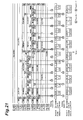
- Fig. 11 is a timing chart in a case of the operation of the embodiment. This figure shows, in order from the top, the operations of the respective pixel units of the eighth row to the first row in the light receiving section 10, the data input operation of the holding section 41 of the first readout section 40, the data output operation from the first readout section 40, the data input operation of the holding section 51 of the second readout section 50, and the data output operation from the second readout section 50.
- the respective "Transfer 1,” “Transfer 2,” “Initialization,” and “Accumulation” in this figure are the same as those in Fig. 9 .
- the respective communication data of the pixel unit P 4,4 and the pixel unit P 4,5 initially read out by the first readout section 40 immediately after the time t correspond to an amount of the charge accumulated over the same period after the time t, before the time t. Therefore, it is possible to accurately receive an optical signal from the optical signal source.
- the solid-state imaging device 1 according to the first embodiment is capable of accurately receiving an optical signal from the optical signal source even in a case where the position of the optical signal source is tracked.
- the image data of each pixel unit of the first row and the sixth row initially read out by the second readout section 50 immediately after the time t correspond to an amount of the charge finally accumulated over a period shorter than usual immediately before the time t
- the image data may be wrong values in some cases.
- these data are not communication data but image data, there may be no problem even if the data are wrong, or the wrong data may be interpolated by use of data of the adjacent rows, which does not become a major problem.
- the solid-state imaging device 1 is capable of operating in various modes.
- the first row selecting section 20 may select the odd-numbered rows in the light receiving section 10
- the second row selecting section 30 may select the even-numbered rows in the light receiving section 10.
- the position of the optical signal source is specified on the basis of image data of the even-numbered rows read out by the second row selecting section 30 and the second readout section 50, and data from the pixel units of any odd-numbered row at the specified position in the image are read out as communication data by the first row selecting section 20 and the first readout section 40.
- the first row selecting section 20 initializes the junction capacitance section of the photodiode PD of each pixel unit of odd-numbered rows other than the row from which the communication data are read out by the first readout section 40.
- the first row selecting section 20 is capable of discharging the junction capacitance section of the photodiode PD of each pixel unit P m3,n of the m3-th row.
- a solid-state imaging device 2 by switching between a first row selecting section 20A and a second row selecting section 20B, it is possible to determine any one of the first row selecting section 20A and the second row selecting section 30A as a row selecting section that outputs a control signal to each pixel unit P m3,n of the m3-th row in the light receiving section 10, thereby discharging the junction capacitance section of the photodiode PD.
- Fig. 12 is a diagram showing a schematic configuration of the solid-state imaging device 2 according to the second embodiment.
- the solid-state imaging device 2 according to the second embodiment shown in Fig. 12 is different in the point that the first row selecting section 20A is included in place of the first row selecting section 20, and is different in the point that the second row selecting section 30A is included in place of the second row selecting section 30, and is different in the point that a control section 60A is included in place of the control section 60.
- the light receiving section 10, the first readout section 40, and the second readout section 50 are respectively the same as those in the first embodiment.
- the control section 60A controls respective operations of the first row selecting section 20A, the second row selecting section 30A, the first readout section 40, and the second readout section 50, to control the entire operation of the solid-state imaging device 2.
- the first row selecting section 20A and the first readout section 40, the second row selecting section 30A and the second readout section 50 are capable of operating in parallel with each other under the control of the control section 60A.
- Fig. 13 is a diagram showing configurations of the first row selecting section 20A and the second row selecting section 30A of the solid-state imaging device 2 according to the second embodiment.
- the first row selecting section 20 includes M control signal generating circuits 23 1 to 23 M composing a first shift register, and M latch circuits 22 1 to 22 M composing a second shift register.
- the second row selecting section 30 includes M control signal generating circuits 33 1 to 33 M composing a first shift register, and M latch circuits 32 1 to 32 M composing a second shift register.
- the respective M control signal generating circuits 23 1 to 23 M included in the first row selecting section 20 have a common configuration, and these are cascade-connected sequentially. That is, an input terminal I of each control signal generating circuit 23 m is connected to an output terminal O of a control signal generating circuit 23 m-1 at the previous stage (here, m is an integer not less than 2 and not more than M).
- a vshift1(0) signal at a high level at a timing of instruction from a clock VCLK1 and at a low level thereafter is input to the input terminal I of the control signal generating circuit 23 1 at the first stage.
- Each control signal generating circuit 23 m operates in synchronization with the clock VCLK1, and when a basic control signal 1 is input, and data row_sel1_data[m] held by a corresponding latch circuit 22 m is at a high level, the control signal generating circuit 23 m outputs the Reset1(m) signal, the Trans1(m) signal, the Hold1(m) signal, and the Address1(m) signal as being at a high level at predetermined timings.
- the M latch circuits 22 1 to 22 M are each a D flip-flop, and these are sequentially cascade-connected. That is, an input terminal D of each latch circuit 22 m is connected to an output terminal Q of a latch circuit 22 m-1 at the previous stage (here, m is an integer not less than 2 and not more than M).
- M-bit data row_sell_data[M:1] are serial-input to the input terminal D of the latch circuit 22 1 at the first stage.
- Each latch circuit 22 m operates in synchronization with a clock row_sel1_clk, to be capable of holding the data row_sel1_data[m].
- Each latch circuit 22 m provides the holding data row_sel1_data[m] to a corresponding control signal generating circuit 23 m , and at the same time, provides it to a control signal generating circuit 33 m as well.
- the first row selecting section 20 is provided with a vshift1(0) signal, a clock VCLK1, a basic control signal 1, M-bit data row_sel1_data[M:1], and a clock row_sel1_clk from the control section 60A.
- the respective M control signal generating circuits 33 1 to 33 M included in the second row selecting section 30 have a common configuration, and these are cascade-connected sequentially. That is, an input terminal I of each control signal generating circuit 33 m is connected to an output terminal O of a control signal generating circuit 33 m-1 at the previous stage (here, m is an integer not less than 2 and not more than M).
- a vshift2(0) signal at a high level at a timing of instruction from a clock VCLK2 and at a low level thereafter is input to the input terminal I of the control signal generating circuit 33 1 at the first stage.
- Each control signal generating circuit 33 m operates in synchronization with the clock VCLK2, and when a basic control signal 2 is input, and data row_sel2_data[m] held by a corresponding latch circuit 32 m is at a high level, the control signal generating circuit 33 m outputs the Reset2(m) signal, the Trans2(m) signal, the Hold2(m) signal, and the Address2(m) signal as being at a high level at predetermined timings.
- the M latch circuits 32 1 to 32 M are each a D flip-flop, and these are sequentially cascade-connected. That is, an input terminal D of each latch circuit 32 m is connected to an output terminal Q of a latch circuit 32 m-1 at the previous stage (here, m is an integer not less than 2 and not more than M).
- M-bit data row_sel2_data[M:1] are serial-input to the input terminal D of the latch circuit 32 1 at the first stage.
- Each latch circuit 32 m operates in synchronization with a clock row_sel2_clk, to be capable of holding the data row_sel2_data[m].
- Each latch circuit 32 m provides the holding data row_sel2_data[m] to a corresponding control signal generating circuit 33 m , and at the same time, provides it to the control signal generating circuit 23 m as well.
- the second row selecting section 30 is provided with a vshift2(0) signal, a clock VCLK2, a basic control signal 2, M-bit data row_sel2_data[M:1], and a clock row_sel2_clk from the control section 60A.
- Fig. 14 is a diagram showing a configuration of a control signal generating circuit 23 m of the first row selecting section 20A of the solid-state imaging device 2 according to the second embodiment.
- Each control signal generating circuit 23 m includes a D flip-flop 210, a NOT circuit 211, AND circuits 212 to 217, OR circuits 218 and 219, an AND circuit 221, NOT circuits 222 and 223, AND circuits 224 and 225, and an OR circuit 226.
- An All_reset1 signal, a Reset1 signal, a Trans 1 signal, a Hold1 signal, an Address1 signal, and a Reset_sel signal are input as the basic control signal 1 described in Fig. 13 to each control signal generating circuit 23 m .
- control signal generating circuit 23 m according to the second embodiment shown in Fig. 14 is different in the point that the NOT circuit 223, the AND circuits 224 to 225, and the OR circuit 226 are further included.
- each control signal generating circuit 23 m allows data logic-inverted from data row_sel2_data[m] output from a corresponding latch circuit 32 m of the second row selecting section 30A by the NOT circuit 222 to be input thereto, and allows the Reset_sel signal as well to be input thereto, and outputs data of logical conjunction of these.
- each control signal generating circuit 23 m allows data row_sel1_data[m] output from a corresponding latch circuit 22 m to be input thereto, and allows data logic-inverted from the Reset_sel signal by the NOT circuit 223 as well to be input thereto, and outputs data of logical conjunction of these.
- the OR circuit 226 of each control signal generating circuit 23 m allows output data from the AND circuit 224 to be input thereto, and allows output data from the AND circuit 225 as well to be input thereto, and outputs data of logical disjunction of these. That is, the OR circuit 226 outputs data logic-inverted from the data row_sel2_data[m] when the Reset_sel signal is at a high level, and outputs the data row_sel1_data[m] when the Reset_sel signal is at a low level.
- each control signal generating circuit 23 m allows output data from the OR circuit 226 to be input thereto, and allows data of the Resent1 signal as well to be input thereto, and outputs data of logical conjunction of these as a Reset1(m) signal.
- each control signal generating circuit 23 m allows output data from the OR circuit 226 to be input thereto, and allows data of the Trans1 signal as well to be input thereto, and outputs data of logical conjunction of these as a Trans 1(m) signal.
- Fig. 15 is a diagram showing a configuration of a control signal generating circuit 33 m of the second row selecting section 30A of the solid-state imaging device 2 according to the second embodiment.
- Each control signal generating circuit 33 m includes a D flip-flop 310, a NOT circuit 311, AND circuits 312 to 317, OR circuits 318 and 319, an AND circuit 321, NOT circuits 322 and 323, AND circuits 324 and 325, and an OR circuit 326.
- An All_reset2 signal, a Reset2 signal, a Trans2 signal, a Hold2 signal, an Address2 signal, and a Reset_sel signal are input as the basic control signal 2 described in Fig. 13 to each control signal generating circuit 33 m .
- control signal generating circuit 33 m according to the second embodiment shown in Fig. 15 is different in the point that the NOT circuits 322 and 323, the AND circuits 324 and 325, and the OR circuit 326 are further included.
- each control signal generating circuit 33 m allows data logic-inverted from data row_sel1_data[m] output from a corresponding latch circuit 22 m of the first row selecting section 20A by the NOT circuit 322 to be input thereto, and allows the Reset_sel signal as well to be input thereto, and outputs data of logical conjunction of these.
- each control signal generating circuit 33 m allows data row_sel2_data[m] output from a corresponding latch circuit 32 m to be input thereto, and allows data logic-inverted from the Reset_sel signal by the NOT circuit 323 as well to be input thereto, and outputs data of logical conjunction of these.
- the OR circuit 326 of each control signal generating circuit 33 m allows output data from the AND circuit 324 to be input thereto, and allows output data from the AND circuit 325 as well to be input thereto, and outputs data of logical disjunction of these. That is, the OR circuit 326 outputs data logic-inverted from the data row_sell_data[m] when the Reset_sel signal is at a high level, and outputs the data row_sel2_data[m] when the Reset_sel signal is at a low level.
- each control signal generating circuit 33 m allows output data from the OR circuit 326 to be input thereto, and allows data of the Reset2 signal as well to be input thereto, and outputs data of logical conjunction of these as a Reset2(m) signal.
- each control signal generating circuit 33 m allows output data from the OR circuit 326 to be input thereto, and allows data of the Trans2 signal as well to be input thereto, and outputs data of logical conjunction of these as a Trans2(m) signal.
- any one of the first row selecting section 20A and the second row selecting section 30A with the configurations shown in Figs. 13 to 15 is capable of performing the function of outputting a control signal to each pixel unit P m3,n of the m3-th row in the light receiving section 10, thereby discharging the junction capacitance section of the photodiode PD according to the Reset_sel signal being at a high level or a low level.
- the first row selecting section 20A in the second embodiment has the same function as the first row selecting section 20 in the first embodiment
- the second row selecting section 30A in the second embodiment has the same function as the second row selecting section 30 in the first embodiment. That is, the first row selecting section 20A has the function of outputting a control signal to each pixel unit P m3,n of the m3-th row in the light receiving section 10, thereby discharging the junction capacitance section of the photodiode PD.
- the solid-state imaging device 2 according to the second embodiment is capable of operating in the same way as the solid-state imaging device 1 according to the first embodiment.
- the second row selecting section 30A has the function of outputting a control signal to each pixel unit P m3,n of the m3-th row in the light receiving section 10, thereby discharging the junction capacitance section of the photodiode PD.
- the solid-state imaging device 2 according to the second embodiment is capable of operating in the same way as the solid-state imaging device 1 according to the first embodiment.
- the first row selecting section or the second row selecting section is to discharge the junction capacitance section of the photodiode PD of each pixel unit P m3,n of the m3-th row.
- a third row selecting section which outputs a control signal to each pixel unit P m3,n of the m3-th row in the light receiving section 10, thereby discharging the junction capacitance section of the photodiode PD is further included.
- the junction capacitance section of the photodiode PD of each pixel unit P m3,n of the m3-th row may be discharged by the third row selecting section in place of the first row selecting section or the second row selecting section.
- Fig. 16 is a diagram showing a schematic configuration of the solid-state imaging device 3 according to the third embodiment. As compared with the schematic configuration of the solid-state imaging device 1 according to the first embodiment shown in Fig. 1 , the solid-state imaging device 3 according to the third embodiment shown in Fig. 16 is different in the point that a third row selecting section 70 is further included.
- the light receiving section 10, the first row selecting section 20, the second row selecting section 30, the first readout section 40, the second readout section 50, and the control section 60 are respectively the same as those in the first embodiment and the second embodiment.
- the third row selecting section 70 selects any m3-th row in the light receiving section 10, and outputs a control signal to each pixel unit P m3,n of the m3-th row, thereby discharging a junction capacitance section of the photodiode, and accumulating charge generated in the photodiode in the charge accumulating section.
- m1 and m2 are integers not less than 1 and not more than M, which are different from each other.
- m3 is an integer not less than 1 and not more than M.
- the first row selecting section 20 and the second row selecting section 30 select rows different from each other in the light receiving section 10.
- the number of rows selected by each of the first row selecting section 20 and the second row selecting section 30 is arbitrary. However, the output of data is sequentially carried out with respect to every single row.
- the number of rows selected by the third row selecting section 70 as well is arbitrary.
- the control section 60 controls respective operations of the first row selecting section 20, the second row selecting section 30, the third row selecting section 70, the first readout section 40, and the second readout section 50, to control the entire operation of the solid-state imaging device 3.
- the first row selecting section 20 and the first readout section 40, the second row selecting section 30 and the second readout section 50 are capable of operating in parallel with each other under the control of the control section 60.
- Fig. 17 is a diagram showing, in the same way as in Fig. 2 , configurations of the first readout section 40 and the second readout section 50 of the solid-state imaging device 3 according to the third embodiment.
- the description of Fig. 17 is the same as the description of Fig. 2 described above, which is therefore omitted.
- Fig. 18 is a diagram showing, in the same way as in Fig. 3 , circuit configurations of a pixel unit P m,n and a holding section 41 n of the solid-state imaging device 3 according to the third embodiment.
- the description of Fig. 18 is the same as the description of Fig. 3 described above, which is therefore omitted.
- a Reset(m) signal is a logical disjunction of a Reset1(m) signal output from the first row selecting section 20, a Reset2(m) signal output from the second row selecting section 30, and a Reset3(m) signal output from the third row selecting section 70.
- a Trans(m) signal is a logical disjunction of a Trans1(m) signal output from the first row selecting section 20, a Trans2(m) signal output from the second row selecting section 30, and a Trans3(m) signal output from the third row selecting section 70.
- Fig. 19 is a diagram showing, in the same way as in Fig. 5 , configurations of the first row selecting section 20, the second row selecting section 30, and the third row selecting section 70 of the solid-state imaging device 3 according to the third embodiment.
- the third row selecting section 70 includes M latch circuits 72 1 to 72 M composing a shift register, M AND circuits 73 1 to 73 M , and MAND circuits 74 1 to 74 M .
- the respective M latch circuits 72 1 to 72 M included in the third row selecting section 70 are each a D flip-flop, and these are sequentially cascade-connected. That is, an input terminal D of each latch circuit 72 m is connected to an output terminal Q of a latch circuit 72 m-1 at the previous stage (here, m is an integer not less than 2 and not more than M).
- M-bit data row_sel3_data[M:1] are serial-input to the input terminal D of the latch circuit 72 1 at the first stage.
- Each latch circuit 72 m operates in synchronization with a clock row_sel3_clk, to be capable of holding the data row_sel3_data[m].
- Each AND circuit 73 m included in the third row selecting section 70 allows data row_sel3_data[m] output from a latch circuit 72 m to be input thereto, and allows data of the Trans3 signal as well to be input thereto, and outputs data of logical conjunction of these as Trans3(m).
- Each AND circuit 74 m allows data row_sel3_data[m] output from a latch circuit 72 m to be input thereto, and allows data of the Reset3 signal as well to be input thereto, and outputs data of logical conjunction of these as Reset3(m).
- the third row selecting section 70 is provided with a Trans3 signal, a Reset3 signal, M-bit data row_sel3_data[M:1], and a clock row_sel3_clk from the control section 60.
- the third row selecting section 70 is capable of outputting control signals (a Reset3(m3) signal, a Trans3(m3) signal) to each pixel unit P m3, n of the m3-th row as being at a high level at predetermined timings.
- Fig. 20 is a diagram showing, in the same way as in Fig. 6 , a configuration of a control signal generating circuit 21 m of the first row selecting section 20 of the solid-state imaging device 3 according to the third embodiment.
- the configuration is different from the configuration of Fig. 6 in the point that each control signal generating circuit 21 m does not include the NOT circuit 222. That is, as shown below, the input to the AND circuits 214 and 215 is different.
- the descriptions of the other configurations are the same as the description of Fig. 6 described above, which is therefore omitted.
- each control signal generating circuit 21 m allows data row_sel1_data[m] output from a corresponding latch circuit 22 m to be input thereto, and allows data of the Reset1 signal as well to be input thereto, and outputs data of logical conjunction of these as a Reset1(m) signal.
- each control signal generating circuit 21 m allows data row_sel1_data[m] output from a corresponding latch circuit 22 m to be input thereto, and allows data of the Trans1 signal as well to be input thereto, and outputs data of logical conjunction of these as a Trans1(m) signal.
- the data row_sel1_data[m1] is set to a high level so as to correspond to the m1-th row to be selected by the first row selecting section 20.
- the data row_sel2_data[m2] is set to a high level so as to correspond to the m2-th row to be selected by the second row selecting section 30.
- the data row_sel3_data[m3] is set to a high level so as to correspond to the m3-th row to be selected by the third row selecting section 70.
- the first row selecting section 20 is capable of outputting a Reset1(m1)signal, a Trans1(m1) signal, a Hold1(m1) signal, and an Address1(m1) signal to each pixel unit P m1,n of the m1-th row as being at a high level at predetermined timings.
- the second row selecting section 30 is capable of outputting a Reset2(m2)signal, a Trans2(m2) signal, a Hold2(m2) signal, and an Address2(m2) signal to each pixel unit P m2,n of the m2-th row as being at a high level at predetermined timings.
- the third row selecting section 70 is capable of outputting a Reset3(m3) signal and a Trans3(m3) signal to each pixel unit P m3,n of the m3-th row as being at a high level at predetermined timings.
- the pixel units in the light receiving section 10 from which data are read out by the first readout section 40 and the second readout section 50 respectively in a case of the operation of the embodiment are the same as those shown in Fig. 8 .
- the junction capacitance section of the photodiode PD in each pixel unit of the fourth row in the light receiving section 10 from which data are read out by the first row selecting section and the first readout section on and after the time t is initialized at a time earlier by a data readout period of the first readout section than the time t by the third row selecting section 70.
- the data of each pixel unit of the fourth row in the light receiving section 10 are read out at a constant time interval on and after the time of initialization immediately before the time t.
- Fig. 21 is a timing chart in a case of the operation of the embodiment. This figure shows, in order from the top, the operations of the respective pixel units of the eighth row to the first row in the light receiving section 10, the data input operation of the holding section 41 of the first readout section 40, the data output operation from the first readout section 40, the data input operation of the holding section 51 of the second readout section 50, and the data output operation from the second readout section 50.
- the respective "Transfer 1,” “transfer 2,” “Initialization,” and “Accumulation” in this figure are the same as those in Fig. 9 .
- the respective communication data of the pixel unit P 4,4 and the pixel unit P 4,5 initially read out by the first readout section 40 immediately after the time t correspond to an amount of the charge accumulated over the same period after the time t, before the time t. Therefore, it is possible to accurately receive an optical signal from an optical signal source.
- the solid-state imaging device 1 according to the present embodiment is capable of accurately receiving an optical signal from the optical signal source even in a case where the position of an optical signal source is tracked.
- the image data may be wrong values in some cases.
- the respective image data of the pixel units P 5,3 to P 5,6 of the fifth row initially read out by the second readout section 50 immediately after the time t correspond to an amount of the charge finally accumulated over a period shorter than usual immediately before the time t
- the image data may be wrong values in some cases.
- these data are not communication data but image data, there may be no problem even if the data are wrong, or the wrong data may be interpolated by use of data of the adjacent rows, which does not become a major problem.
- the solid-state imaging device 3 is capable of operating in various modes.
- the first row selecting section 20 may select the odd-numbered rows in the light receiving section 10
- the second row selecting section 30 may select the even-numbered rows in the light receiving section 10.
- the position of the optical signal source is specified on the basis of image data of the even-numbered rows read out by the second row selecting section 30 and the second readout section 50, and data from the pixel units of any odd-numbered row at the specified position in the image are read out as communication data by the first row selecting section 20 and the first readout section 40.
- the third row selecting section 70 initializes the junction capacitance section of the photodiode PD of each pixel unit of the m3-th row from which the communication data are newly read out in advance of the start of readout.
- the solid-state imaging device 3 according to the third embodiment is capable of operating as shown in Figs. 22 and 23 .
- Figs. 22 are diagrams for describing pixel units in the light receiving section 10 from which data are read out by the first readout section 40 and the second readout section 50 respectively in a case of the operation of another embodiment.
- respective communication data of the pixel unit P 5,3 and the pixel unit P 5,4 in the light receiving section 10 are read out by the first row selecting section and the first readout section (the region A in Fig. 22(a) ), and respective communication data of the pixel unit P 6,6 and the pixel unit P 6,7 in the light receiving section 10 are read out by the second row selecting section and the second readout section (the region B in Fig. 22(a) ).
- respective communication data of the pixel unit P 4,2 and the pixel unit P 4,3 in the light receiving section 10 are read out by the first row selecting section and the first readout section (the region A in Fig. 22(c) ), and respective communication data of the pixel unit P 7,6 and the pixel unit P 7,7 in the light receiving section 10 are read out by the second row selecting section and the second readout section (the region B in Fig. 22(c) ).
- the two optical signal sources which are independently movable between each other are present, and data of an optical signal from one of the optical signal sources are read out by the first row selecting section and the first readout section, and data of an optical signal from the other optical signal source are read out by the second row selecting section and the second readout section.
- Fig. 23 is a timing chart in a case of the operation of another embodiment.
- This figure shows, in order from the top, the operations of the respective pixel units of the eighth row to the first row in the light receiving section 10, the data input operation of the holding section 41 of the first readout section 40, the data output operation from the first readout section 40, the data input operation of the holding section 51 of the second readout section 50, and the data output operation from the second readout section 50.
- the respective "Transfer 1,” “Transfer 2,” “Initialization,” and “Accumulation” in this figure are the same as those in Fig. 9 .
- the data read out by the first readout section and the data read out by the second readout section are the same in period with each other, but different in phase.
- the rows whose data are read out by the first row selecting section and the first readout section are changed with the time t 1 serving as a boundary.
- the respective communication data of the pixel unit P 4,2 and the pixel unit P 4,3 initially read out by the first readout section immediately after the time t 1 correspond to an amount of the charge accumulated over the same period after the time t 1 , before the time t 1 .
- the rows whose data are read out by the second row selecting section and the second readout section are changed with the time t 2 serving as a boundary.
- the solid-state imaging device 1 is capable of accurately receiving an optical signal from each optical signal source even in a case where the respective positions of the two optical signal sources are tracked.
- the present invention is applicable for use for accurately receiving an optical signal from the optical signal source even in a case where the position of an optical signal source is tracked in a solid-state imaging device for optical communication.
Abstract
Description
- The present invention relates to a solid-state imaging device.
- A solid-state imaging device includes a light receiving section where M×N pixel units P1,1 to PM,N each including a photodiode and a charge accumulating section are two-dimensionally arrayed in M rows and N columns, a row selecting section that causes each pixel unit Pm,n in a light receiving section to accumulate charge generated in the photodiode during a given period in its charge accumulating section, and to output data corresponding to an amount of the charge accumulated in each pixel unit Pm,n in every row, and a readout section for which the data output from each pixel unit Pm,n in the light receiving section is input and from which data corresponding to an amount of charge generated in the photodiode of each pixel unit Pm,n is output. Also, in some cases, the solid-state imaging device further includes an AD conversion section that analog/digital-converts the data output from the readout section to output a digital value.
- Such a solid-state imaging device is capable of detecting an intensity of light reaching each pixel unit Pm,n in its light receiving section, to perform imaging. Further, in recent years, not only imaging, but an attempt has been made to perform optical communication by using such a solid-state imaging device. For example, a solid-state imaging device of the invention disclosed in
Patent Literature 1 has a plurality of means for reading out data from each pixel unit, and is capable of performing imaging by reading out data by every pixel unit with the first readout means among those. Further, the solid-state imaging device adds current signals generated from photodiodes of specific one pixel unit, or two or more pixel units to output the signal with the second readout means, so that the solid-state imaging device is capable of receiving an optical signal. - Patent Literature 1: Japanese Patent No.
3995959 - In the solid-state imaging device of the invention disclosed in
Patent Literature 1, because the data to be read out by the first readout means is image data, a data readout speed by the first readout means is, for example, several tens of fps (frame per second). On the other hand, because the data to be read out by the second readout means is communication data, a data readout speed by the second readout means is, for example, several tens of kbps (kilo bit per second). - The present inventors have found that the following problems occur in such a solid-state imaging device that performs imaging and optical communication. The solid-state imaging device of the invention disclosed in
Patent Literature 1 is intended to be used for a case where an optical signal source may be moved. In this case, the position of the optical signal source is specified on the basis of image data read out by the first readout means, and data from the pixel units at the specified position in the image are read out as communication data by the second readout means. - In the case where the position of the optical signal source is tracked in this way, from a given pixel unit, image data are read out by the first readout means before a given time t, and communication data are read out by the second readout means on and after the time t. Further, from a given pixel unit, no data are read out by either of the first readout means or the second readout means before a given time t, and communication data are read out by the second readout means on and after the time t. That is, in the pixel unit, the charge accumulating time before the time t is longer than the charge accumulating time on and after the time t. However, because the communication data initially read out by the second readout means immediately after the time t correspond to an amount of the charge finally accumulated over a long period immediately before the time t, the communication data may be wrong values in some cases. Under such circumstances, the solid-state imaging device is not able to accurately receive an optical signal from the optical signal source.
- The present invention has been achieved in order to solve the above-described problems. An object of the present invention is to provide a solid-state imaging device for optical communication, which is capable of accurately receiving an optical signal from the optical signal source even in a case where the position of an optical signal source is tracked.
- A solid-state imaging device according to the present invention includes (1) a light receiving section where M×N pixel units P1,1 to PM,N each including a photodiode that generates charge of an amount according to an incident light amount, a charge accumulating section in which the charge is accumulated, a first switch for outputting data corresponding to an accumulated charge amount in the charge accumulating section, and a second switch for outputting data corresponding to the accumulated charge amount in the charge accumulating section are two-dimensionally arrayed in M rows and N columns, (2) a first row selecting section which selects any m1-th row in the light receiving section, and outputs a control signal to each pixel unit Pm1,n of the m1-th row, thereby discharging a junction capacitance section of the photodiode, accumulating the charge generated in the photodiode in the charge accumulating section, and outputting data corresponding to the accumulated charge amount in the charge accumulating section to a readout signal line L1n by closing the first switch, (3) a second row selecting section which selects any m2-th row different from the m1-th row in the light receiving section, and outputs a control signal to each pixel unit Pm2,n of the m2-th row, thereby discharging a junction capacitance section of the photodiode, accumulating the charge generated in the photodiode in the charge accumulating section, and outputting data corresponding to the accumulated charge amount in the charge accumulating section to a readout signal line L2n by closing the second switch, (4) a first readout section which is connected to N readout signal lines L11 to L1N, for which data output from each pixel unit Pm1,n of the m1-th row in the light receiving section selected by the first row selecting section to the readout signal line L1n is input thereto, and from which data corresponding to an amount of the charge generated in the photodiode of each pixel unit Pm1,n of the m1-th row is output, and (5) a second readout section which is connected to N readout signal lines L21 to L2N, for which data output from each pixel unit Pm2,n of the m2-th row in the light receiving section selected by the second row selecting section to the readout signal line L2n is input thereto, and from which data corresponding to an amount of the charge generated in the photodiode of each pixel unit Pm2,n of the m2-th row is output. Moreover, the solid-state imaging device according to the present invention selects any m3-th row in the light receiving section, and outputs a control signal to each pixel unit Pm3,n of the m3-th row, thereby discharging a junction capacitance section of the photodiode, and the first row selecting section and the first readout section, and the second row selecting section and the second readout section operate in parallel with each other (provided that M and N are integers not less than 2, m1 and m2 are integers not less than 1 and not more than M, which are different from each other, m3 is an integer not less than 1 and not more than M, and n is an integer not less than 1 and not more than N).
- In the solid-state imaging device according to the present invention, any m1-th row in the light receiving section is selected by the first row selecting section, and in each pixel unit Pm1,n of the m1-th row, the junction capacitance section of the photodiode is discharged, the charge generated in the photodiode is accumulated in the charge accumulating section, and the data corresponding to the accumulated charge amount in the charge accumulating section is output to the readout signal line L1n by closing the first switch. In the first readout section which is connected to each readout signal L1n, data output from each pixel unit Pm1,n of the m1-th row in the light receiving section selected by the first row selecting section to the readout signal line L1n is input thereto, and data corresponding to the amount of charge generated in the photodiode of each pixel unit Pm1,n of the m1-th row is output.
- On the other hand, any m2-th row in the light receiving section is selected by the second row selecting section, and in each pixel unit Pm2,n of the m2-th row, the junction capacitance section of the photodiode is discharged, the charge generated in the photodiode is accumulated in the charge accumulating section, and the data corresponding to the accumulated charge amount in the charge accumulating section is output to a readout signal line L2n by closing the second switch. In the second readout section which is connected to each readout signal line L2n, data output from each pixel unit Pm2,n of the m2-th row in the light receiving section selected by the second row selecting section to the readout signal line L2n is input thereto, and data corresponding to the amount of charge generated in the photodiode of each pixel unit Pm2,n of the m2-th row is output.
- Rows different from each other in the light receiving section are selected by the first row selecting section and the second row selecting section. Then, the first row selecting section and the first readout section, and the second row selecting section and the second readout section operate in parallel with each other. Thereby, for example, image data by the first row selecting section and the first readout section is obtained, and communication data by the second row selecting section and the second readout section is obtained.
- Further, in the solid-state imaging device according to the present invention, any m3-th row in the light receiving section is selected, and in each pixel unit Pm3,n of the m3-th row, the junction capacitance section of the photodiode is discharged.
- In the solid-state imaging device according to the present invention, it is preferable that the first row selecting section or the second row selecting section select any m3-th row different from the m1-th row and the m2-th row in the light receiving section, and outputs a control signal to each pixel unit Pm3,n of the m3-th row, thereby discharging the junction capacitance section of the photodiode. However, m1, m2, and m3 are integers not less than 1 and not more than M, which are different from each other. In the solid-state imaging device according to the present invention, any m3-th row different from the m1-th row and the m2-th row in the light receiving section is selected by the first row selecting section or the second row selecting section, and in each pixel unit Pm3,n of the m3-th row, the junction capacitance section of the photodiode is discharged.
- It is preferable that the solid-state imaging device according to the present invention further include switching means for switching between the first row selecting section and the second row selecting section, to determine any one of the first row selecting section and the second row selecting section as a row selecting section which outputs a control signal to each pixel unit Pm3,n of the m3-th row in the light receiving section, thereby discharging the junction capacitance section of the photodiode.
- It is preferable that, in the solid-state imaging device according to the present invention, (a) the first row selecting section include M latch circuits, and when data held in an m1-th latch circuit among the M latch circuits is a significant value, the first row selecting section output a control signal to each pixel unit Pm1,n of the m1-th row, (b) the second row selecting section include M latch circuits, and when data held in an m2-th latch circuit among the M latch circuits is a significant value, the second row selecting section output a control signal to each pixel unit Pm2,n of the m2-th row, and (c) any row selecting section of the first row selecting section and the second row selecting section output a control signal to each pixel unit Pm3,n of the m3-th row when data held in an m3-th latch circuit among the M latch circuits of the other row selecting section is an insignificant value.
- In the solid-state imaging device according to the present invention, it is preferable that the M latch circuits of each of the first row selecting section and the second row selecting section be cascade-connected in order of the rows, to compose a shift register, and M-bit data be serial-input to a latch circuit at the first stage in the shift register, to cause each latch circuit to hold data.
- In the solid-state imaging device according to the present invention, it is preferable that (a) the first row selecting section sequentially output the control signals at a constant time interval to a plurality of rows corresponding to latch circuits with holding data of significant values among the M latch circuits included in the first row selecting section, and (b) the second row selecting section sequentially output the control signals at a constant time interval to a plurality of rows corresponding to latch circuits with holding data of significant values among the M latch circuits included in the second row selecting section.
- It is preferable that the solid-state imaging device according to the present invention further include a third row selecting section which selects any m3-th row in the light receiving section, and outputs a control signal to each pixel unit Pm3,n of the m3-th row, thereby discharging a junction capacitance section of the photodiode. In the solid-state imaging device according to the present invention, any m3-th row in the light receiving section is selected by the third row selecting section, and in each pixel unit Pm3,n of the m3-th row, the junction capacitance section of the photodiode is discharged
- It is preferable that, in the solid-state imaging device according to the present invention, (a) the first row selecting section include M latch circuits, and when data held in an m1-th latch circuit among the M latch circuits is a significant value, the first row selecting section output a control signal to each pixel unit Pm1,n of the m1-th row, (b) the second row selecting section include M latch circuits, and when data held in an m2-th latch circuit among the M latch circuits is a significant value, the second row selecting section output a control signal to each pixel unit Pm2,n of the m2-th row, and (c) the third row selecting section include M latch circuits, and when data held in an m3-th latch circuit among the M latch circuits is a significant value, the third row selecting section output a control signal to each pixel unit Pm3,n of the m3-th row.
- In the solid-state imaging device according to the present invention, it is preferable that the M latch circuits of each of the first row selecting section, the second row selecting section, and the third row selecting section be cascade-connected in order of the rows, to compose a shift register, and M-bit data be serial-input to a latch circuit at the first stage in the shift register, to cause each latch circuit to hold data.
- In the solid-state imaging device according to the present invention, it is preferable that (a) the first row selecting section sequentially output the control signals at a constant time interval to a plurality of rows corresponding to latch circuits with holding data of significant values among the M latch circuits included in the first row selecting section, and (b) the second row selecting section sequentially output the control signals at a constant time interval to a plurality of rows corresponding to latch circuits with holding data of significant values among the M latch circuits included in the second row selecting section.
- The solid-state imaging device of the present invention is capable of accurately receiving an optical signal from the optical signal source even in a case where the position of an optical signal source is tracked.
-
-
Fig. 1 is a diagram showing a schematic configuration of a solid-state imaging device 1 according to a first embodiment. -
Fig. 2 is a diagram showing configurations of afirst readout section 40 and asecond readout section 50 of the solid-state imaging device 1 according to the first embodiment. -
Fig. 3 is a diagram showing circuit configurations of a pixel unit Pm,n and aholding section 41n of the solid-state imaging device 1 according to the first embodiment. -
Fig. 4 is a diagram showing a circuit configuration of a differencearithmetic section 43 of the solid-state imaging device 1 according to the first embodiment. -
Fig. 5 is a diagram showing configurations of a firstrow selecting section 20 and a secondrow selecting section 30 of the solid-state imaging device 1 according to the first embodiment. -
Fig. 6 is a diagram showing a configuration of a control signal generating circuit 21m of the firstrow selecting section 20 of the solid-state imaging device 1 according to the first embodiment. -
Fig. 7 is a diagram showing a configuration of a controlsignal generating circuit 31m of the secondrow selecting section 30 of the solid-state imaging device 1 according to the first embodiment. -
Figs. 8 are diagrams for describing pixel units in alight receiving section 10 from which data are read out by thefirst readout section 40 and thesecond readout section 50 respectively in a case of the operation of a comparison example. -
Fig. 9 is a timing chart in a case of the operation of the comparison example. -
Figs. 10 are diagrams for describing pixel units in thelight receiving section 10 from which data are read out by thefirst readout section 40 and thesecond readout section 50 respectively in a case of the operation of an embodiment. -
Fig. 11 is a timing chart in a case of the operation of the embodiment. -
Fig. 12 is a diagram showing a schematic configuration of a solid-state imaging device 2 according to a second embodiment. -
Fig. 13 is a diagram showing configurations of a firstrow selecting section 20A and a secondrow selecting section 30A of the solid-state imaging device 2 according to the second embodiment. -
Fig. 14 is a diagram showing a configuration of a controlsignal generating circuit 23m of the firstrow selecting section 20A of the solid-state imaging device 2 according to the second embodiment. -
Fig. 15 is a diagram showing a configuration of a control signal generating circuit 33m of the secondrow selecting section 30A of the solid-state imaging device 2 according to the second embodiment. -
Fig. 16 is a diagram showing a schematic configuration of a solid-state imaging device 3 according to a third embodiment. -
Fig. 17 is a diagram showing configurations of afirst readout section 40 and asecond readout section 50 of the solid-state imaging device 3 according to the third embodiment. -
Fig. 18 is a diagram showing circuit configurations of a pixel unit Pm,n and a holdingsection 41n of the solid-state imaging device 3 according to the third embodiment. -
Fig. 19 is a diagram showing configurations of a firstrow selecting section 20, a secondrow selecting section 30, and a thirdrow selecting section 70 of the solid-state imaging device 3 according to the third embodiment. -
Fig. 20 is a diagram showing a configuration of a control signal generating circuit 21m of the firstrow selecting section 20 of the solid-state imaging device 3 according to the third embodiment. -
Fig. 21 is a timing chart in a case of the operation of the embodiment. -
Figs. 22 are diagrams for describing pixel units in thelight receiving section 10 from which data are read out by thefirst readout section 40 and thesecond readout section 50 respectively in a case of the operation of another embodiment. -
Fig. 23 is a timing chart in a case of the operation of another embodiment. - Hereinafter, embodiments of the present invention will be described in detail with reference to the accompanying drawings. Also, the same components will be denoted with the same reference numerals in the description of the drawings, and overlapping description will be omitted.
- (First Embodiment)
-
Fig. 1 is a diagram showing a schematic configuration of a solid-state imaging device 1 according to a first embodiment. The solid-state imaging device 1 shown in this figure includes alight receiving section 10, a firstrow selecting section 20, a secondrow selecting section 30, afirst readout section 40, asecond readout section 50, and acontrol section 60. - The
light receiving section 10 includes M×N pixel units P1,1 to PM,N. The M×N pixel units P1,1 to PM,N have a common configuration, and these are two-dimensionally arrayed in M rows and N columns. Each pixel unit Pm,n is located in the m-th row and the n-th column. Here, M and N are integers not less than 2, and m is an integer not less than 1 and not more than M, and n is an integer not less than 1 and not more than N. - Each pixel unit Pm,n has a photodiode that generates charge of an amount according to an incident light amount and a charge accumulating section in which the charge is accumulated. Each pixel unit Pm,n is capable of discharging a junction capacitance section of the photodiode, accumulating charge generated in the photodiode in its charge accumulating section, and outputting data corresponding to the accumulated charge amount in the charge accumulating section to a readout signal line L1n or a readout signal line L2n on the basis of various control signals received via control signal lines from the first
row selecting section 20 or the secondrow selecting section 30. - The first
row selecting section 20 selects any m1-th row in thelight receiving section 10, and outputs a control signal to each pixel unit Pm1,n of the m1-th row, thereby discharging a junction capacitance section of the photodiode, accumulating the charge generated in the photodiode in the charge accumulating section, and outputting data corresponding to the accumulated charge amount in the charge accumulating section to the readout signal line L1n. - The second
row selecting section 30 selects any m2-th row in thelight receiving section 10, and outputs a control signal to each pixel unit Pm2,n of the m2-th row, thereby discharging a junction capacitance section of the photodiode, accumulating the charge generated in the photodiode in the charge accumulating section, and outputting data corresponding to the accumulated charge amount in the charge accumulating section to the readout signal line L2n. - The first
row selecting section 20 selects any m3-th row in thelight receiving section 10, and outputs a control signal to each pixel unit Pm3,n of the m3-th row, thereby discharging a junction capacitance section of the photodiode, and accumulating the charge generated in the photodiode in the charge accumulating section. - Here, m1, m2, and m3 are integers not less than 1 and not more than M, which are different from each other. The first
row selecting section 20 and the secondrow selecting section 30 select rows different from each other in thelight receiving section 10. The number of rows selected by each of the firstrow selecting section 20 and the secondrow selecting section 30 is arbitrary. However, the output of data is sequentially carried out with respect to every single row. - The
first readout section 40 is connected to N readout signal lines L11 to L1N, and data output from each pixel unit Pm1,n of the m1-th row in thelight receiving section 10 selected by the firstrow selecting section 20 to the readout signal line L1n is input thereto, and data corresponding to an amount of charge generated in the photodiode of each pixel unit Pm1,n of the m1-th row is output therefrom. - The
second readout section 50 is connected to N readout signal lines L21 to L2N, data output from each pixel unit Pm2,n of the m2-th row in thelight receiving section 10 selected by the secondrow selecting section 30 to the readout signal line L2n is input thereto, and data corresponding to an amount of charge generated in the photodiode of each pixel unit Pm2,n of the m2-th row is output therefrom. - The
control section 60 controls respective operations of the firstrow selecting section 20, the secondrow selecting section 30, thefirst readout section 40, and thesecond readout section 50, to control the entire operation of the solid-state imaging device 1. The firstrow selecting section 20 and thefirst readout section 40, the secondrow selecting section 30 and thesecond readout section 50 are capable of operating in parallel with each other under the control of thecontrol section 60. -
Fig. 2 is a diagram showing configurations of thefirst readout section 40 and thesecond readout section 50 of the solid-state imaging device 1 according to the first embodiment. In this figure, the pixel unit Pm,n of the m-th row and the n-th column is shown as a representative of the M×N pixel units P1,1 to PM,N in thelight receiving section 10. Further, constitutional elements relating to the pixel unit Pm,n are shown in each of thefirst readout section 40 and thesecond readout section 50. - The
first readout section 40 includesN holding sections 411 to 41N, a firstcolumn selecting section 42, and a differencearithmetic section 43. TheN holding sections 411 to 41N have a common configuration. Each holdingsection 41n is connected to M pixel units P1,n to PM,n of the n-th column in thelight receiving section 10 via the readout signal line L1n, and allows data output from the pixel unit Pm1,n of the m1-th row selected by the firstrow selecting section 20 to the readout signal line L1n to be input thereto, to hold the data, and is capable of outputting the held data. Each holdingsection 41n preferably allows data of signal components superimposed with noise components to be input thereto, to hold the data, and for allowing data of only noise components to be input thereto, to hold the data. - The
N holding sections 411 to 41N are capable of sampling data at a same timing on the basis of various control signals received from the firstcolumn selecting section 42, to hold the sampled data, and sequentially output the held data. Thedifference arithmetic section 43 allows the data sequentially output from the respectiveN holding sections 411 to 41N to be input thereto, and subtracts the data of only noise components from the data of signal components superimposed with noise components, to output data corresponding to the signal components. Thedifference arithmetic section 43 may output the data corresponding to the signal components as analog data, or may have an AD conversion function to output digital data. In this way, thefirst readout section 40 is capable of outputting data corresponding to an amount of charge generated in the photodiode of each pixel unit Pm1,n of the m1-th row. - The
second readout section 50 includesN holding sections 511 to 51N, a secondcolumn selecting section 52, and a differencearithmetic section 53. TheN holding sections 511 to 51N have a common configuration. Each holdingsection 51n is connected to M pixel units P1,n to PM,n of the n-th column in thelight receiving section 10 via the readout signal line L2n, and allows data output from the pixel unit Pm2,n of the m2-th row selected by the secondrow selecting section 20 to the readout signal line L2n to be input thereto, to hold the data, and is capable of outputting the held data. Each holdingsection 51n preferably allows data of signal components superimposed with noise components to be input thereto, to hold the data, and for allowing data of only noise components to be input thereto, to hold the data. - The
N holding sections 511 to 51N are capable of sampling data at a same timing on the basis of various control signals received from the secondcolumn selecting section 52, to hold the sampled data, and sequentially output the held data. Thedifference arithmetic section 53 allows the data sequentially output from the respectiveN holding sections 511 to 51N to be input thereto, and subtracts the data of only noise components from the data of signal components superimposed with noise components, to output data corresponding to the signal components. Thedifference arithmetic section 53 may output the data corresponding to the signal components as analog data, or may have an AD conversion function to output digital data. In this way, thesecond readout section 50 is capable of outputting data corresponding to an amount of charge generated in the photodiode of each pixel unit Pm2,n of the m2-th row. -
Fig. 3 is a diagram showing circuit configurations of the pixel unit Pm,n and the holdingsection 41n of the solid-state imaging device 1 according to the first embodiment. In this figure as well, the pixel unit Pm,n of the m-th row and the n-th column is shown as a representative of the M×N pixel units P1,1 to PM,N in thelight receiving section 10. Further, the holdingsection 41n relating to the pixel unit Pm,n is shown in thefirst readout section 40. In addition, the configuration of the holdingsection 51n is the same as the configuration of the holdingsection 41n. - Each pixel unit Pm,n is of the APS (Active Pixel Sensor) type, that includes a photodiode PD and 6 MOS transistors T1, T2, T3, T41, T42, and T5. As shown in this figure, the transistor T1, the transistor T2, and the photodiode PD are sequentially connected in series, and a reference voltage is input to the drain terminal of the transistor T1, and the anode terminal of the photodiode PD is grounded. The connection point between the transistor T1 and the transistor T2 is connected to the gate terminal of the transistor T3 via the transistor T5.
- A reference voltage is input to the drain terminal of the transistor T3. The source terminal of the transistor T3 is connected to the respective drain terminals of the transistors T41 and T42. The source terminal of the transistor T41 of each pixel unit Pm,n is connected to the readout signal line L1n. The source terminal of the transistor T42 of each pixel unit Pm,n is connected to the readout signal line L2n. A constant current source is connected to the readout signal line L1n and the readout signal line L2n, respectively.
- The gate terminal of the transistor T2 for transfer in each pixel unit Pm,n is connected to a control signal line LTm, and a Trans(m) signal output from the first
row selecting section 20 or the secondrow selecting section 30 is input thereto. The gate terminal of the transistor T1 for reset in each pixel unit Pm,n is connected to a control signal line LRm, and a Reset(m) signal output from the firstrow selecting section 20 or the secondrow selecting section 30 is input thereto. The gate terminal of the transistor T5 for hold in each pixel unit Pm,n is connected to a control signal line LHm, and a Hold(m) signal output from the firstrow selecting section 20 or the secondrow selecting section 30 is input thereto. - The gate terminal of the transistor T41 for output selection in each pixel unit Pm,n is connected to a control signal line LA1m, and an Address1(m) signal output from the first
row selecting section 20 is input thereto. The gate terminal of the transistor T42 for output selection in each pixel unit Pm,n is connected to a control signal line LA2m, and an Address2(m) signal output from the secondrow selecting section 30 is input thereto. These control signals (a Reset(m) signal, a Trans(m) signal, a Hold(m) signal, an Address1(m) signal, and an Address2(m) signal) are input in common to the N pixel units Pm,1 to Pm,N of the m-th row. - The control signal line LTm, the control signal line LRm, and the control signal line LHm are provided to every row, and the control signals (a Reset(m) signal, a Trans(m) signal, a Hold(m) signal) giving instructions for discharge from each of the junction capacitance section of the photodiode PD in each pixel unit Pm,n of the m-th row and the charge accumulating section, and for charge accumulation by the charge accumulating section are transmitted therethrough. The Reset(m) signal is a logical disjunction of a Reset1(m) signal output from the first
row selecting section 20 and a Reset2(m) signal output from the secondrow selecting section 30. The Trans(m) signal is a logical disjunction of a Trans1(m) signal output from the firstrow selecting section 20 and a Trans2(m) signal output from the secondrow selecting section 30. Further, the Hold(m) signal is a logical disjunction of a Hold1(m) signal output from the firstrow selecting section 20 and a Hold2(m) signal output from the secondrow selecting section 30. - The control signal line LA1m and the control signal line LA2m are provided to every row, and the control signals (an Address1(m) signal, an Address2(m) signal) for giving instructions for data output to the readout signal line L1n or the readout signal line L2n in each pixel unit Pm,n of the m-th row are transmitted therethrough. Each control signal line LA1m is connected to the first
row selecting section 20. Each control signal line LA2m is connected to the secondrow selecting section 30. The Address1(m) signal and the Address2(m) signal are not raised to a high level simultaneously, and the transistor T41 and the transistor T42 do not move into an ON state simultaneously. - When the Reset(m) signal, the Trans(m) signal, and the Hold(m) signal are at a high level, the junction capacitance section of the photodiode PD is discharged, and further, a diffusion region (the charge accumulating section) connected to the gate terminal of the transistor T3 is discharged. When the Trans(m) signal is at a low level, the charge generated in the photodiode PD is accumulated in the junction capacitance section. When the Reset(m) signal is at a low level and the Trans(m) signal and the Hold(m) signal are at a high level, the charge accumulated in the junction capacitance section of the photodiode PD is transferred to the diffusion region (the charge accumulating section) connected to the gate terminal of the transistor T3 to be accumulated therein.
- When the Address1(m) signal is at a high level, data (data of signal components superimposed with noise components) corresponding to an amount of the charge accumulated in the diffusion region (the charge accumulating section) connected to the gate terminal of the transistor T3 is output to the readout signal line L1n via the transistor T41, to be input to the holding
section 41n of thefirst readout section 40. That is, the transistor T41 operates as a first switch for outputting data corresponding to an accumulated charge amount in the charge accumulating section to the readout signal line L1n. In addition, when the charge accumulating section is in a state of discharge, data of only noise components is output to the readout signal line L1n via the transistor T41. - When the Address2(m) signal is at a high level, data (data of signal components superimposed with noise components) corresponding to an amount of the charge accumulated in the diffusion region (the charge accumulating section) connected to the gate terminal of the transistor T3 is output to the readout signal line L2n via the transistor T42, to be input to the holding
section 51n of thesecond readout section 50. That is, the transistor T42 operates as a second switch for outputting data corresponding to an accumulated charge amount in the charge accumulating section to the readout signal line L2n. In addition, when the charge accumulating section is in a state of discharge, data of only noise components is output to the readout signal line L2n via the transistor T42. - Each holding
section 41n includes two capacitive elements C1 and C2, and four switches SW11, SW12, SW2, and SW22. In this holdingsection 41n, the switch SW11 and the switch SW12 are connected in series to be provided between the readout signal line L1n and a wiring Hline_s1, and one terminal of the capacitive element C1 is connected to the connection point between the switch SW11 and the switch SW12, and the other terminal of the capacitive element C1 is grounded. Further, the switch SW21, and the switch SW22 are connected in series to be provided between the readout signal line L1n and a wiring Hline_n1, and one terminal of the capacitive element C2 is connected to the connection point between the switch SW21 and the switch SW22, and the other terminal of the capacitive element C2 is grounded. - In this holding
section 41n, the switch SW11 opens and closes according to a level of a set_s1 signal supplied from the firstcolumn selecting section 42. The switch SW21 opens and closes according to a level of a set_n1 signal supplied from the firstcolumn selecting section 42. The set_s1 signal and the set_n1 signal are input in common to theN holding sections 411 to 41N. The switches SW12 and SW22 open and close according to a level of an hshift1(n) signal supplied from the firstcolumn selecting section 42. - In this holding
section 41n, when the set_n1 signal is shifted from a high level to a low level and the switch SW21 opens, the noise components output from the pixel unit Pm,n to the readout signal line L1n are thereafter held as a voltage value out_n1(n) by the capacitive element C2. When the set_s1 signal is shifted from a high level to a low level and the switch SW11 opens, the signal components superimposed with noise components output from the pixel unit Pm,n to the readout signal line L1n are thereafter held as a voltage value out_s1(n) by the capacitive element C1. Then, when the hshift1(n) signal is raised to a high level, the switch SW12 is closed to output the voltage value out_s1(n) held by the capacitive element C1 to the wiring Hline_s1, and the switch SW22 is closed to output the voltage value out_n1(n) held by the capacitive element C2 to the wiring Hline_n1. A difference between these voltage value out_s1(n) and voltage value out_n1(n) represents a voltage value corresponding to an amount of charge generated in the photodiode PD of the pixel unit Pm,n. -
Fig. 4 is a diagram showing a circuit configuration of thedifference arithmetic section 43 of the solid-state imaging device 1 according to the first embodiment. In addition, the configuration of thedifference arithmetic section 53 is the same as the configuration of thedifference arithmetic section 43. As shown in this figure, thedifference arithmetic section 43 includes amplifiers A1 to A3, switches SW1 and SW2, and resistors R1 to R4. The inverting input terminal of the amplifier A3 is connected to the output terminal of the buffer amplifier A1 via the resistor R1, and is connected to its own output terminal via the resistor R3. The non-inverting input terminal of the amplifier A3 is connected to the output terminal of the buffer amplifier A2 via the resistor R2, and is connected to a grounding potential via the resistor R4. The input terminal of the buffer amplifier A1 is connected to theN holding sections 411 to 41N via the wiring Hline_s1, and is connected to a grounding potential via the switch SW1. The input terminal of the buffer amplifier A2 is connected to theN holding sections 411 to 41N via the wiring Hline_n1, and is connected to a grounding potential via the switch SW2. - The switches SW1 and SW2 in the
difference arithmetic section 43 are controlled by an hresetl signal supplied from the firstcolumn selecting section 42 to carry out an opening and closing operation. When the switch SW1 is closed, the voltage value input to the input terminal of the buffer amplifier A1 is reset. When the switch SW2 is closed, the voltage value input to the input terminal of the buffer amplifier A2 is reset. When the switches SW1 and SW2 are open, the voltage values out_s1(n) and out_n1(n) output to the wirings Hline_s1 and Hline_n1 from any holdingsection 41n among theN holding sections 411 to 41N are input to the input terminals of the buffer amplifiers A1 and A2. Assuming that the respective gains of the buffer amplifiers A1 and A2 are 1, and the respective resistance values of the four resistors R1 to R4 are equal to one another, a voltage value output from the output terminal of thedifference arithmetic section 43 represents a difference between the voltage values respectively input via the wiring Hline_s1 and the wiring Hline_n1, that is the value from which noise components are eliminated. -
Fig. 5 is a diagram showing configurations of the firstrow selecting section 20 and the secondrow selecting section 30 of the solid-state imaging device 1 according to the first embodiment. As shown in this figure, the firstrow selecting section 20 includes M control signal generating circuits 211 to 21M composing a first shift register, andM latch circuits 221 to 22M composing a second shift register. Further, the secondrow selecting section 30 includes M controlsignal generating circuits 311 to 31M composing a first shift register, andM latch circuits 321 to 32M composing a second shift register. - The respective M control signal generating circuits 211 to 21M included in the first
row selecting section 20 have a common configuration, and these are cascade-connected sequentially. That is, an input terminal I of each control signal generating circuit 21m is connected to an output terminal O of a control signal generating circuit 21m-1 at the previous stage (here, m is an integer not less than 2 and not more than M). A vshift1(0) signal at a high level at a timing of instruction from a clock VCLK1 and at a low level thereafter is input to the input terminal I of the control signal generating circuit 211 at the first stage. Each control signal generating circuit 21m operates in synchronization with the clock VCLK1, and when abasic control signal 1 is input, and data row_sell_data[m] held by acorresponding latch circuit 22m is at a high level, the control signal generating circuit 21m outputs the Reset1(m) signal, the Trans1(m) signal, the Hold1(m) signal, and the Address1(m) signal as being at a high level at predetermined timings. - The
M latch circuits 221 to 22M are each a D flip-flop, and these are sequentially cascade-connected. That is, an input terminal D of eachlatch circuit 22m is connected to an output terminal Q of alatch circuit 22m-1 at the previous stage (here, m is an integer not less than 2 and not more than M). M-bit data row_sel1_data[M:1] are serial-input to the input terminal D of thelatch circuit 221 at the first stage. Eachlatch circuit 22m operates in synchronization with a clock row_sel1_clk, to be capable of holding the data row_sel1_data[m]. Eachlatch circuit 22m provides the holding data row_sel1_data[m] to a corresponding control signal generating circuit 21m. - The first
row selecting section 20 is provided with a vshift1(0) signal, a clock VCLK1, abasic control signal 1, M-bit data row_sel1_data[M:1], and a clock row_sel1_clk from thecontrol section 60. - The respective M control
signal generating circuits 311 to 31M included in the secondrow selecting section 30 have a common configuration, and those are cascade-connected sequentially. That is, an input terminal I of each controlsignal generating circuit 31m is connected to an output terminal O of a controlsignal generating circuit 31m-1 at the previous stage (here, m is an integer not less than 2 and not more than M). A vshift2(0) signal at a high level at a timing of instruction from a clock VCLK2 and at a low level thereafter is input to the input terminal I of the controlsignal generating circuit 311 at the first stage. Each controlsignal generating circuit 31m operates in synchronization with the clock VCLK2, and when abasic control signal 2 is input, and data row_sel2_data[m] held by acorresponding latch circuit 32m is at a high level, the controlsignal generating circuit 31m outputs the Reset2(m) signal, the Trans2(m) signal, the Hold2(m) signal, and the Address2(m) signal as being at a high level at predetermined timings. - The
M latch circuits 321 to 32M are each a D flip-flop, and these are sequentially cascade-connected. That is, an input terminal D of eachlatch circuit 32m is connected to an output terminal Q of alatch circuit 32m-1 at the previous stage (here, m is an integer not less than 2 and not more than M). M-bit data row_sel2_data[M:1] are serial-input to the input terminal D of thelatch circuit 321 at the first stage. Eachlatch circuit 32m operates in synchronization with a clock row_sel2_clk, to be capable of holding the data row_sel2_data[m]. Eachlatch circuit 32m provides the holding data row_sel2_data[m] to a corresponding controlsignal generating circuit 31m, and at the same time, provides it to the control signal generating circuit 21m as well. - The second
row selecting section 30 is provided with a vshift2(0) signal, a clock VCLK2, abasic control signal 2, M-bit data row_seI2_data[M:l], and a clock row_sel2_clk from thecontrol section 60. -
Fig. 6 is a diagram showing a configuration of a control signal generating circuit 21m of the firstrow selecting section 20 of the solid-state imaging device 1 according to the first embodiment. Each control signal generating circuit 21m includes a D flip-flop 210, aNOT circuit 211, ANDcircuits 212 to 217, ORcircuits circuit 221, and aNOT circuit 222. An All_reset1 signal, a Reset1 signal, a Trans1 signal, a Hold1 signal, and anAddress 1 signal are input as thebasic control signal 1 described inFig. 5 to each control signal generating circuit 21m. - The D flip-
flop 210 of each control signal generating circuit 21m allows a vshift1(m-1) signal output from a control signal generating circuit 21m-1 at the previous stage to be input thereto, to hold the data at a timing of instruction from the clock VCLK1, and outputs the held data. - The AND
circuit 212 of each control signal generating circuit 21m allows the data row_sel1_data[m] output from acorresponding latch circuit 22m to be input thereto, and allows data output from the D flip-flop 210 as well to be input thereto, and outputs data of logical conjunction of these. - The AND
circuit 213 of each control signal generating circuit 21m allows data that the data row_sel1_data[m] output from acorresponding latch circuit 22m is logic-inverted by theNOT circuit 211 to be input thereto, and allows data of a vshift1(m-1) signal output from a control signal generating circuit 21m-1 at the previous stage as well to be input thereto, and outputs data of logical conjunction of these. - The OR
circuit 218 of each control signal generating circuit 21m allows respective data from the ANDcircuit 212 and the ANDcircuit 213 to be input thereto, and outputs data of logical disjunction of these as a vshift1(m) signal. - The AND
circuit 214 of each control signal generating circuit 21m allows data logic-inverted from the data row_sel2_data[m] output from acorresponding latch circuit 32m of the secondrow selecting section 30 by theNOT circuit 222 to be input thereto, and allows data of the Reset1 signal as well to be input thereto, and outputs data of logical conjunction of these as a Reset1(m) signal. - The AND
circuit 215 of each control signal generating circuit 21m allows data logic-inverted from the data row_sel2_data[m] output from acorresponding latch circuit 32m of the secondrow selecting section 30 by theNOT circuit 222 to be input thereto, and allows data of the Trans1 signal as well to be input thereto, and outputs data of logical conjunction of these as a Trans1(m) signal. - The AND
circuit 221 of each control signal generating circuit 21m allows data row_sel1_data[m] output from acorresponding latch circuit 22m, and allows data of the All_reset1 signal as well to be input thereto, and outputs data of logical conjunction of these. - The OR
circuit 219 of each control signal generating circuit 21m allows output data from the ANDcircuit 221 to be input thereto, and allows output data from the ANDcircuit 212 as well to be input thereto, and outputs data of logical disjunction of these. - The AND
circuit 216 of each control signal generating circuit 21m allows output data from theOR circuit 219 to be input thereto, and allows data of the Hold1 signal as well to be input thereto, and outputs data of logical conjunction of these as a Hold1(m) signal. - The AND
circuit 217 of each control signal generating circuit 21m allows data of the Address1 signal to be input thereto, and allows output data from the ANDcircuit 212 as well to be input thereto, and outputs data of logical conjunction of these as an Address1(m) signal. -
Fig. 7 is a diagram showing a configuration of the controlsignal generating circuit 31m of the secondrow selecting section 30 of the solid-state imaging device 1 according to the first embodiment. Each controlsignal generating circuit 31m includes a D flip-flop 310, aNOT circuit 311, ANDcircuits 312 to 317, ORcircuits circuit 321. An All_reset2 signal, a Reset2 signal, a Trans2 signal, a Hold2 signal, and an Address2 signal are input as thebasic control signal 2 described inFig. 5 to each controlsignal generating circuit 31m. - The D flip-
flop 310 of each controlsignal generating circuit 31m allows a vshift2(m-1) signal output from a controlsignal generating circuit 31m-1 at the previous stage to be input thereto, to hold the data at a timing of instruction from the clock VCLK2, and outputs the held data. - The AND
circuit 312 of each controlsignal generating circuit 31m allows data row_sel2_data[m] output from acorresponding latch circuit 32m to be input thereto, and allows data output from the D flip-flop 310 as well to be input thereto, and outputs data of logical conjunction of these. - The AND
circuit 313 of each controlsignal generating circuit 31m allows data logic-inverted from data row_sel2_data[m] output from acorresponding latch circuit 32m by theNOT circuit 311 to be input thereto, and allows data of a vshift2(m-1) signal output from a controlsignal generating circuit 31m-1 at the previous stage as well to be input thereto, and outputs data of logical conjunction of these. - The OR
circuit 318 of each controlsignal generating circuit 31m allows respective data from the ANDcircuit 312 and the ANDcircuit 313 to be input thereto, and outputs data of logical disjunction of these as a vshift2(m) signal. - The AND
circuit 314 of each controlsignal generating circuit 31m allows data row_sel2_data[m] output from acorresponding latch circuit 32m to be input thereto, and allows data of the Reset2 signal as well to be input thereto, and outputs data of logical conjunction of these as a Reset2(m) signal. - The AND
circuit 315 of each controlsignal generating circuit 31m allows data row_sel2_data[m] output from acorresponding latch circuit 32m to be input thereto, and allows data of the Trans2 signal as well to be input thereto, and outputs data of logical conjunction of these as a Trans2(m) signal. - The AND
circuit 321 of each controlsignal generating circuit 31m allows data row_sel2_data[m] output from acorresponding latch circuit 32m to be input thereto, and allows data of the All_reset2 signal as well to be input thereto, and outputs data of logical conjunction of these. - The OR
circuit 319 of each controlsignal generating circuit 31m allows output data from the ANDcircuit 321 to be input thereto, and allows output data from the ANDcircuit 312 as well to be input thereto, and outputs data of logical disjunction of these. - The AND
circuit 316 of each controlsignal generating circuit 31m allows output data from theOR circuit 319 to be input thereto, and allows data of the Hold2 signal as well to be input thereto, and outputs data of logical conjunction of these as a Hold2(m) signal. - The AND
circuit 317 of each controlsignal generating circuit 31m allows data of the Address2 signal to be input thereto, and allows output data from the ANDcircuit 312 as well to be input thereto, and outputs data of logical conjunction of these as an Address2(m) signal. - The data row_sell_data[m1] is set to a high level so as to correspond to the m1-th row to be selected by the first
row selecting section 20. Further, the data row_sel2_data[m2] is set to a high level so as to correspond to the m2-th row to be selected by the secondrow selecting section 30. In order to make the m1-th row selected by the firstrow selecting section 20 and the m2-th row selected by the secondrow selecting section 30 be different from each other, it is necessary for the data row_sel1_data[m] and the data row_sel2_data[m] both to be not at a high level, and for at least one of these to be at a low level with respect to each m value. - In the first
row selecting section 20 with the configuration shown inFig. 6 , in the case where the data row_sell_data[m1] held in an m1-th latch circuit 22m1 among theM latch circuits 221 to 22M is at a high level (at this time, the data row_sel2_data[m1] is necessarily at a low level), a control signal generating circuit 21m1 corresponding thereto is capable of outputting control signals (a Reset1(m1) signal, a Trans1(m1) signal, a Hold1(m1) signal) to each pixel unit Pm1, n of the m1-th row as being at a high level at predetermined timings, and outputting an Address1(m) signal as well as being at a high level at a predetermined timing. - Further, in the first
row selecting section 20, a control signal generating circuit corresponding to a latch circuit whose holding data row_sel1_data[m] is at a low level among theM latch circuits 221 to 22M is capable of outputting the vshift1 signal reaching from the previous stage immediately to the subsequent stage. That is, only latch circuits whose holding data row_sell_data[m] are at a high level among theM latch circuits 221 to 22M compose a substantive shift register. Therefore, the firstrow selecting section 20 is capable of sequentially outputting control signals at a constant time interval (a period of the clock VCLK1) to rows corresponding to latch circuits whose holding data row_sel1_data[m] are at a high level among theM latch circuits 221 to 22M. - In the second
row selecting section 30 with the configuration shown inFig. 7 , in the case where the data row_sel2_data[m2] held in an m2-th latch circuit 32m2 among theM latch circuits 321 to 32M is at a high level (at this time, the data row_sel1_data[m2] is necessarily at a low level), a controlsignal generating circuit 31m2 corresponding thereto is capable of outputting control signals (a Reset2(m2) signal, a Trans2(m2) signal, a Hold2(m2) signal) to each pixel unit Pm2, n of the m2-th row as being at a high level at predetermined timings, and outputting an Address2(m2) signal as well as being at a high level at a predetermined timing. - Further, in the second
row selecting section 30, a control signal generating circuit corresponding to a latch circuit whose holding data row_sel2_data[m] is at a low level among theM latch circuits 321 to 32M is capable of outputting the vshift2 signal reaching from the previous stage immediately to the subsequent stage. That is, only latch circuits whose holding data row_sel2_data[m] are at a high level among theM latch circuits 321 to 32M compose a substantive shift register. Therefore, the secondrow selecting section 30 is capable of sequentially outputting control signals at a constant time interval (a period of the clock VCLK2) to rows corresponding to latch circuits whose holding data row-sel2_data[m] are at a high level among theM latch circuits 321 to 32M. - Moreover, in the case where the data row_sel1_data[m3] held in an m3-
th latch circuit 22m3 among theM latch circuits 221 to 22M in the firstrow selecting section 20 are at a low level, and the data row_sel2_data[m3] held in an m3-th latch circuit 32m3 among theM latch circuits 321 to 32M in the secondrow selecting section 30 as well are at a low level, a corresponding control signal generating circuit 21m3 of the firstrow selecting section 20 is capable of outputting control signals (a Reset1(m3) signal, a Trans1(m3) signal) to each pixel unit Pm3,n of the m3-th row as being at a high level at predetermined timings, but does not output a Hold1(m3) signal and an Address1(m3) signal as being at a high level at predetermined timings in any case. - That is, the first
row selecting section 20 selects all the rows which are neither the m1-th row selected by the firstrow selecting section 20 nor the m2-th row selected by the secondrow selecting section 30 among the first to M-th rows in thelight receiving section 10, as the m3-th rows, and outputs a control signal to each pixel unit Pm3,n of the m3-th rows, thereby it is possible to discharge the junction capacitance section of the photodiode PD, and to accumulate the charge generated in the photodiode in the charge accumulating section. - Next, an embodiment (
Figs. 10 and11 ) of the operation of the solid-state imaging device 1 according to the first embodiment will be described in comparison with a comparison example (Figs. 8 and9 ). In the comparison example, both of the first row selecting section and the second row selecting section do not discharge the junction capacitance section of the photodiode with respect to each pixel unit Pm3,n of any m3-th row different from the m1-th row and the m2-th row in thelight receiving section 10. In both of the embodiment and the comparison example, it is assumed that M = N = 8 for convenience of description. -
Figs. 8 are diagrams for describing pixel units in thelight receiving section 10 from which data are read out by thefirst readout section 40 and thesecond readout section 50 respectively in a case of the operation of the comparison example. In the comparison example, before a given time t, as shown inFig. 8(a) , respective communication data of the pixel unit P5,3 and the pixel unit P5,4 in thelight receiving section 10 are read out by the first row selecting section and the first readout section (the region A inFig. 8(a) ), and respective image data of the pixel unit P3,2 to the pixel unit P3,5, the pixel unit P4,2 to the pixel unit P4,5, the pixel unit P6,2 to the pixel unit P6,5, and the pixel unit P7,2 to the pixel unit P7,5 in thelight receiving section 10 are read out by the second row selecting section and the second readout section (the region B inFig. 8(a) ). - Then, in the comparison example, after the time t, as shown in
Fig. 8(b) , respective communication data of the pixel unit P4,4 and the pixel unit P4,5 in thelight receiving section 10 are read out by the first row selecting section and the first readout section (the region A inFig. 8(b) ), and respective image data of the pixel unit P2,3 to the pixel unit P2,6, the pixel unit P3,3 to the pixel unit P3,6, the pixel unit P5,3 to the pixel unit P5,6, and the pixel unit P6,3 to the pixel unit P6,6 in thelight receiving section 10 are read out by the second row selecting section and the second readout section (the region B inFig. 8(b) ). - That is, in the comparison example, the regions A and B in the pixel units in the
light receiving section 10 read out by the first readout section or the second readout section are shifted by an amount of one pixel respectively in the row direction and the column direction with the given time t serving as a boundary. -
Fig. 9 is a timing chart in a case of the operation of the comparison example. This figure shows, in order from the top, the operations of the respective pixel units of the eighth row to the first row in thelight receiving section 10, the data input operation of the holdingsection 41 of thefirst readout section 40, the data output operation from thefirst readout section 40, the data input operation of the holdingsection 51 of thesecond readout section 50, and the data output operation from thesecond readout section 50. - In the figure, the "
Transfer 1" means that the charge in the junction capacitance section of the photodiode PD is transferred to an FD region (a diffusion region (the charge accumulating section) connected to the gate terminal of the transistor T3) by bringing the transistor T2 and the transistor T5 into an ON state in a pixel unit. The "Transfer 2" means that data corresponding to an accumulated charge amount in the charge accumulating section is transferred to the holdingsection 41 or the holdingsection 51 by bringing the transistor T41 or the transistor T42 into an ON state in a pixel unit. The "Initialization" means that the charge in the junction capacitance section of the photodiode PD is discharged to be initialized by bringing the transistor T1 and the transistor T2 into an ON state in a pixel unit. The "Accumulation" means that charge generated in the photodiode PD is accumulated in the junction capacitance section by bringing the transistor T1 into an OFF state in a pixel unit. - As shown in this figure, in the comparison example, because the respective communication data of the pixel unit P4,4 and the pixel unit P4,5 initially read out by the
first readout section 40 immediately after the time t correspond to an amount of the charge finally accumulated over a long period immediately before the time t, the communication data may be wrong values in some cases. Therefore, it is impossible to accurately receive an optical signal from the optical signal source. - On the other hand, in this comparison example, because the respective image data of the pixel units P2,3 to P2,6 of the second row initially read out by the
second readout section 50 immediately after the time t correspond to an amount of the charge finally accumulated over a period longer than usual immediately before the time t, the image data may be wrong values in some cases. Further, because the respective image data of the pixel units P5,3 to P5,6 of the fifth row initially read out by thesecond readout section 50 immediately after the time t correspond to an amount of the charge finally accumulated over a period shorter than usual immediately before the time t, the image data may be wrong values in some cases. However, because these data are not communication data but image data, there may be no problem even if the data are wrong, or the wrong data may be interpolated by use of data of the adjacent rows, which does not become a major problem. -
Figs. 10 are diagrams for describing pixel units in thelight receiving section 10 from which data are read out by thefirst readout section 40 and thesecond readout section 50 respectively in a case of the operation of the embodiment. In the embodiment, before a given time t, as shown inFig. 10(a) , respective communication data of the pixel unit P5,3 and the pixel unit P5,4 in thelight receiving section 10 are read out by the first row selecting section and the first readout section (the region A inFig. 10(a) ), and respective image data of the pixel unit P2,2 to the pixel unit P2,5, the pixel unit P3,2 to the pixel unit P3,5, the pixel unit P7,2 to the pixel unit P7,5, and the pixel unit P8,2 to the pixel unit P8,5 in thelight receiving section 10 are read out by the second row selecting section and the second readout section (the region B inFig. 10(a) ). Further, by the firstrow selecting section 20, the junction capacitance section of the photodiode PD in each pixel unit of each of the first row, the fourth row, and the sixth row is initialized at the same timing as the junction capacitance section of the photodiode PD in each pixel unit of the fifth row. - Then, in the embodiment, after the time t, as shown in
Fig. 10(b) , respective communication data of the pixel unit P4,4 and the pixel unit P4,5 in thelight receiving section 10 are read out by the first row selecting section and the first readout section (the region A inFig. 10(b) ), and respective image data of the pixel unit P1,3 to the pixel unit P1,6, the pixel unit P2,3 to the pixel unit P2,6, the pixel unit P6,3 to the pixel unit P6,6, and the pixel unit P7,3 to the pixel unit P7,6 in thelight receiving section 10 are read out by the second row selecting section and the second readout section (the region B inFig. 10(b) ). Further, by the firstrow selecting section 20, the junction capacitance section of the photodiode PD in each pixel unit of each of the third row, the fifth row, and the eighth row is initialized at the same timing as the junction capacitance section of the photodiode PD in each pixel unit of the fourth row. - That is, in the embodiment, the regions A and B in the pixel units in the
light receiving section 10 read out by the first readout section or the second readout section are shifted by an amount of one pixel respectively in the row direction and the column direction with the given time t serving as a boundary, and further, rows onto which only initialization of the junction capacitance section of the photodiode PD is carried out by the firstrow selecting section 20 are shifted down by an amount of one row. -
Fig. 11 is a timing chart in a case of the operation of the embodiment. This figure shows, in order from the top, the operations of the respective pixel units of the eighth row to the first row in thelight receiving section 10, the data input operation of the holdingsection 41 of thefirst readout section 40, the data output operation from thefirst readout section 40, the data input operation of the holdingsection 51 of thesecond readout section 50, and the data output operation from thesecond readout section 50. The respective "Transfer 1," "Transfer 2," "Initialization," and "Accumulation" in this figure are the same as those inFig. 9 . - As shown in this figure, in the embodiment, the respective communication data of the pixel unit P4,4 and the pixel unit P4,5 initially read out by the
first readout section 40 immediately after the time t correspond to an amount of the charge accumulated over the same period after the time t, before the time t. Therefore, it is possible to accurately receive an optical signal from the optical signal source. In this way, the solid-state imaging device 1 according to the first embodiment is capable of accurately receiving an optical signal from the optical signal source even in a case where the position of the optical signal source is tracked. - On the other hand, in this embodiment, because the image data of each pixel unit of the first row and the sixth row initially read out by the
second readout section 50 immediately after the time t correspond to an amount of the charge finally accumulated over a period shorter than usual immediately before the time t, the image data may be wrong values in some cases. However, because these data are not communication data but image data, there may be no problem even if the data are wrong, or the wrong data may be interpolated by use of data of the adjacent rows, which does not become a major problem. - In addition, the solid-
state imaging device 1 according to the first embodiment is capable of operating in various modes. For example, the firstrow selecting section 20 may select the odd-numbered rows in thelight receiving section 10, and the secondrow selecting section 30 may select the even-numbered rows in thelight receiving section 10. In this case, the position of the optical signal source is specified on the basis of image data of the even-numbered rows read out by the secondrow selecting section 30 and thesecond readout section 50, and data from the pixel units of any odd-numbered row at the specified position in the image are read out as communication data by the firstrow selecting section 20 and thefirst readout section 40. In this case, the firstrow selecting section 20 initializes the junction capacitance section of the photodiode PD of each pixel unit of odd-numbered rows other than the row from which the communication data are read out by thefirst readout section 40. - (Second Embodiment)
- Next, a second embodiment will be described. In the solid-
state imaging device 1 according to the first embodiment, only the firstrow selecting section 20 is capable of discharging the junction capacitance section of the photodiode PD of each pixel unit Pm3,n of the m3-th row. On the other hand, in a solid-state imaging device 2 according to a second embodiment, by switching between a firstrow selecting section 20A and a second row selecting section 20B, it is possible to determine any one of the firstrow selecting section 20A and the secondrow selecting section 30A as a row selecting section that outputs a control signal to each pixel unit Pm3,n of the m3-th row in thelight receiving section 10, thereby discharging the junction capacitance section of the photodiode PD. -
Fig. 12 is a diagram showing a schematic configuration of the solid-state imaging device 2 according to the second embodiment. As compared with the schematic configuration of the solid-state imaging device 1 according to the first embodiment shown inFig. 1 , the solid-state imaging device 2 according to the second embodiment shown inFig. 12 is different in the point that the firstrow selecting section 20A is included in place of the firstrow selecting section 20, and is different in the point that the secondrow selecting section 30A is included in place of the secondrow selecting section 30, and is different in the point that acontrol section 60A is included in place of thecontrol section 60. Thelight receiving section 10, thefirst readout section 40, and thesecond readout section 50 are respectively the same as those in the first embodiment. - The
control section 60A controls respective operations of the firstrow selecting section 20A, the secondrow selecting section 30A, thefirst readout section 40, and thesecond readout section 50, to control the entire operation of the solid-state imaging device 2. The firstrow selecting section 20A and thefirst readout section 40, the secondrow selecting section 30A and thesecond readout section 50 are capable of operating in parallel with each other under the control of thecontrol section 60A. -
Fig. 13 is a diagram showing configurations of the firstrow selecting section 20A and the secondrow selecting section 30A of the solid-state imaging device 2 according to the second embodiment. As shown in this figure, the firstrow selecting section 20 includes M controlsignal generating circuits 231 to 23M composing a first shift register, andM latch circuits 221 to 22M composing a second shift register. Further, the secondrow selecting section 30 includes M control signal generating circuits 331 to 33M composing a first shift register, andM latch circuits 321 to 32M composing a second shift register. - The respective M control
signal generating circuits 231 to 23M included in the firstrow selecting section 20 have a common configuration, and these are cascade-connected sequentially. That is, an input terminal I of each controlsignal generating circuit 23m is connected to an output terminal O of a controlsignal generating circuit 23m-1 at the previous stage (here, m is an integer not less than 2 and not more than M). A vshift1(0) signal at a high level at a timing of instruction from a clock VCLK1 and at a low level thereafter is input to the input terminal I of the controlsignal generating circuit 231 at the first stage. Each controlsignal generating circuit 23m operates in synchronization with the clock VCLK1, and when abasic control signal 1 is input, and data row_sel1_data[m] held by acorresponding latch circuit 22m is at a high level, the controlsignal generating circuit 23m outputs the Reset1(m) signal, the Trans1(m) signal, the Hold1(m) signal, and the Address1(m) signal as being at a high level at predetermined timings. - The
M latch circuits 221 to 22M are each a D flip-flop, and these are sequentially cascade-connected. That is, an input terminal D of eachlatch circuit 22m is connected to an output terminal Q of alatch circuit 22m-1 at the previous stage (here, m is an integer not less than 2 and not more than M). M-bit data row_sell_data[M:1] are serial-input to the input terminal D of thelatch circuit 221 at the first stage. Eachlatch circuit 22m operates in synchronization with a clock row_sel1_clk, to be capable of holding the data row_sel1_data[m]. Eachlatch circuit 22m provides the holding data row_sel1_data[m] to a corresponding controlsignal generating circuit 23m, and at the same time, provides it to a control signal generating circuit 33m as well. - The first
row selecting section 20 is provided with a vshift1(0) signal, a clock VCLK1, abasic control signal 1, M-bit data row_sel1_data[M:1], and a clock row_sel1_clk from thecontrol section 60A. - The respective M control signal generating circuits 331 to 33M included in the second
row selecting section 30 have a common configuration, and these are cascade-connected sequentially. That is, an input terminal I of each control signal generating circuit 33m is connected to an output terminal O of a control signal generating circuit 33m-1 at the previous stage (here, m is an integer not less than 2 and not more than M). A vshift2(0) signal at a high level at a timing of instruction from a clock VCLK2 and at a low level thereafter is input to the input terminal I of the control signal generating circuit 331 at the first stage. Each control signal generating circuit 33m operates in synchronization with the clock VCLK2, and when abasic control signal 2 is input, and data row_sel2_data[m] held by acorresponding latch circuit 32m is at a high level, the control signal generating circuit 33m outputs the Reset2(m) signal, the Trans2(m) signal, the Hold2(m) signal, and the Address2(m) signal as being at a high level at predetermined timings. - The
M latch circuits 321 to 32M are each a D flip-flop, and these are sequentially cascade-connected. That is, an input terminal D of eachlatch circuit 32m is connected to an output terminal Q of alatch circuit 32m-1 at the previous stage (here, m is an integer not less than 2 and not more than M). M-bit data row_sel2_data[M:1] are serial-input to the input terminal D of thelatch circuit 321 at the first stage. Eachlatch circuit 32m operates in synchronization with a clock row_sel2_clk, to be capable of holding the data row_sel2_data[m]. Eachlatch circuit 32m provides the holding data row_sel2_data[m] to a corresponding control signal generating circuit 33m, and at the same time, provides it to the controlsignal generating circuit 23m as well. - The second
row selecting section 30 is provided with a vshift2(0) signal, a clock VCLK2, abasic control signal 2, M-bit data row_sel2_data[M:1], and a clock row_sel2_clk from thecontrol section 60A. -
Fig. 14 is a diagram showing a configuration of a controlsignal generating circuit 23m of the firstrow selecting section 20A of the solid-state imaging device 2 according to the second embodiment. Each controlsignal generating circuit 23m includes a D flip-flop 210, aNOT circuit 211, ANDcircuits 212 to 217, ORcircuits circuit 221, NOTcircuits circuits circuit 226. An All_reset1 signal, a Reset1 signal, aTrans 1 signal, a Hold1 signal, an Address1 signal, and a Reset_sel signal are input as thebasic control signal 1 described inFig. 13 to each controlsignal generating circuit 23m. - As compared with the configuration of the control signal generating circuit 21m according to the first embodiment shown in
Fig. 6 , the controlsignal generating circuit 23m according to the second embodiment shown inFig. 14 is different in the point that theNOT circuit 223, the ANDcircuits 224 to 225, and theOR circuit 226 are further included. - The AND
circuit 224 of each controlsignal generating circuit 23m allows data logic-inverted from data row_sel2_data[m] output from acorresponding latch circuit 32m of the secondrow selecting section 30A by theNOT circuit 222 to be input thereto, and allows the Reset_sel signal as well to be input thereto, and outputs data of logical conjunction of these. - The AND
circuit 225 of each controlsignal generating circuit 23m allows data row_sel1_data[m] output from acorresponding latch circuit 22m to be input thereto, and allows data logic-inverted from the Reset_sel signal by theNOT circuit 223 as well to be input thereto, and outputs data of logical conjunction of these. - The OR
circuit 226 of each controlsignal generating circuit 23m allows output data from the ANDcircuit 224 to be input thereto, and allows output data from the ANDcircuit 225 as well to be input thereto, and outputs data of logical disjunction of these. That is, theOR circuit 226 outputs data logic-inverted from the data row_sel2_data[m] when the Reset_sel signal is at a high level, and outputs the data row_sel1_data[m] when the Reset_sel signal is at a low level. - The AND
circuit 214 of each controlsignal generating circuit 23m allows output data from theOR circuit 226 to be input thereto, and allows data of the Resent1 signal as well to be input thereto, and outputs data of logical conjunction of these as a Reset1(m) signal. - The AND
circuit 215 of each controlsignal generating circuit 23m allows output data from theOR circuit 226 to be input thereto, and allows data of the Trans1 signal as well to be input thereto, and outputs data of logical conjunction of these as a Trans 1(m) signal. -
Fig. 15 is a diagram showing a configuration of a control signal generating circuit 33m of the secondrow selecting section 30A of the solid-state imaging device 2 according to the second embodiment. Each control signal generating circuit 33m includes a D flip-flop 310, aNOT circuit 311, ANDcircuits 312 to 317, ORcircuits circuit 321, NOTcircuits circuits circuit 326. An All_reset2 signal, a Reset2 signal, a Trans2 signal, a Hold2 signal, an Address2 signal, and a Reset_sel signal are input as thebasic control signal 2 described inFig. 13 to each control signal generating circuit 33m. - As compared with the configuration of the control
signal generating circuit 31m according to the first embodiment shown inFig. 7 , the control signal generating circuit 33m according to the second embodiment shown inFig. 15 is different in the point that theNOT circuits circuits OR circuit 326 are further included. - The AND
circuit 324 of each control signal generating circuit 33m allows data logic-inverted from data row_sel1_data[m] output from acorresponding latch circuit 22m of the firstrow selecting section 20A by theNOT circuit 322 to be input thereto, and allows the Reset_sel signal as well to be input thereto, and outputs data of logical conjunction of these. - The AND
circuit 325 of each control signal generating circuit 33m allows data row_sel2_data[m] output from acorresponding latch circuit 32m to be input thereto, and allows data logic-inverted from the Reset_sel signal by theNOT circuit 323 as well to be input thereto, and outputs data of logical conjunction of these. - The OR
circuit 326 of each control signal generating circuit 33m allows output data from the ANDcircuit 324 to be input thereto, and allows output data from the ANDcircuit 325 as well to be input thereto, and outputs data of logical disjunction of these. That is, theOR circuit 326 outputs data logic-inverted from the data row_sell_data[m] when the Reset_sel signal is at a high level, and outputs the data row_sel2_data[m] when the Reset_sel signal is at a low level. - The AND
circuit 314 of each control signal generating circuit 33m allows output data from theOR circuit 326 to be input thereto, and allows data of the Reset2 signal as well to be input thereto, and outputs data of logical conjunction of these as a Reset2(m) signal. - The AND
circuit 315 of each control signal generating circuit 33m allows output data from theOR circuit 326 to be input thereto, and allows data of the Trans2 signal as well to be input thereto, and outputs data of logical conjunction of these as a Trans2(m) signal. - Any one of the first
row selecting section 20A and the secondrow selecting section 30A with the configurations shown inFigs. 13 to 15 is capable of performing the function of outputting a control signal to each pixel unit Pm3,n of the m3-th row in thelight receiving section 10, thereby discharging the junction capacitance section of the photodiode PD according to the Reset_sel signal being at a high level or a low level. - In the case where the Reset_sel signal is at a high level, the first
row selecting section 20A in the second embodiment has the same function as the firstrow selecting section 20 in the first embodiment, and the secondrow selecting section 30A in the second embodiment has the same function as the secondrow selecting section 30 in the first embodiment. That is, the firstrow selecting section 20A has the function of outputting a control signal to each pixel unit Pm3,n of the m3-th row in thelight receiving section 10, thereby discharging the junction capacitance section of the photodiode PD. Accordingly, in this case, the solid-state imaging device 2 according to the second embodiment is capable of operating in the same way as the solid-state imaging device 1 according to the first embodiment. - On the other hand, in the case where the Reset_sel signal is at a low level, the second
row selecting section 30A has the function of outputting a control signal to each pixel unit Pm3,n of the m3-th row in thelight receiving section 10, thereby discharging the junction capacitance section of the photodiode PD. Except for this point, the solid-state imaging device 2 according to the second embodiment is capable of operating in the same way as the solid-state imaging device 1 according to the first embodiment. - (Third Embodiment)
- Next, a third embodiment will be described. In the solid-
state imaging device 1 according to the first embodiment and the solid-state imaging device 2 according to the second embodiment, the first row selecting section or the second row selecting section is to discharge the junction capacitance section of the photodiode PD of each pixel unit Pm3,n of the m3-th row. On the other hand, in a solid-state imaging device 3 according to the third embodiment, a third row selecting section which outputs a control signal to each pixel unit Pm3,n of the m3-th row in thelight receiving section 10, thereby discharging the junction capacitance section of the photodiode PD is further included. In this way, the junction capacitance section of the photodiode PD of each pixel unit Pm3,n of the m3-th row may be discharged by the third row selecting section in place of the first row selecting section or the second row selecting section. -
Fig. 16 is a diagram showing a schematic configuration of the solid-state imaging device 3 according to the third embodiment. As compared with the schematic configuration of the solid-state imaging device 1 according to the first embodiment shown inFig. 1 , the solid-state imaging device 3 according to the third embodiment shown inFig. 16 is different in the point that a thirdrow selecting section 70 is further included. Thelight receiving section 10, the firstrow selecting section 20, the secondrow selecting section 30, thefirst readout section 40, thesecond readout section 50, and thecontrol section 60 are respectively the same as those in the first embodiment and the second embodiment. - In place of the first
row selecting section 20 or the second row selecting section in the first embodiment and the second embodiment, the thirdrow selecting section 70 selects any m3-th row in thelight receiving section 10, and outputs a control signal to each pixel unit Pm3,n of the m3-th row, thereby discharging a junction capacitance section of the photodiode, and accumulating charge generated in the photodiode in the charge accumulating section. - Here, m1 and m2 are integers not less than 1 and not more than M, which are different from each other. m3 is an integer not less than 1 and not more than M. The first
row selecting section 20 and the secondrow selecting section 30 select rows different from each other in thelight receiving section 10. The number of rows selected by each of the firstrow selecting section 20 and the secondrow selecting section 30 is arbitrary. However, the output of data is sequentially carried out with respect to every single row. The number of rows selected by the thirdrow selecting section 70 as well is arbitrary. - The
control section 60 controls respective operations of the firstrow selecting section 20, the secondrow selecting section 30, the thirdrow selecting section 70, thefirst readout section 40, and thesecond readout section 50, to control the entire operation of the solid-state imaging device 3. The firstrow selecting section 20 and thefirst readout section 40, the secondrow selecting section 30 and thesecond readout section 50 are capable of operating in parallel with each other under the control of thecontrol section 60. -
Fig. 17 is a diagram showing, in the same way as inFig. 2 , configurations of thefirst readout section 40 and thesecond readout section 50 of the solid-state imaging device 3 according to the third embodiment. The description ofFig. 17 is the same as the description ofFig. 2 described above, which is therefore omitted. -
Fig. 18 is a diagram showing, in the same way as inFig. 3 , circuit configurations of a pixel unit Pm,n and a holdingsection 41n of the solid-state imaging device 3 according to the third embodiment. The description ofFig. 18 is the same as the description ofFig. 3 described above, which is therefore omitted. - In addition, in
Fig. 18 , a Reset(m) signal is a logical disjunction of a Reset1(m) signal output from the firstrow selecting section 20, a Reset2(m) signal output from the secondrow selecting section 30, and a Reset3(m) signal output from the thirdrow selecting section 70. Further, a Trans(m) signal is a logical disjunction of a Trans1(m) signal output from the firstrow selecting section 20, a Trans2(m) signal output from the secondrow selecting section 30, and a Trans3(m) signal output from the thirdrow selecting section 70. -
Fig. 19 is a diagram showing, in the same way as inFig. 5 , configurations of the firstrow selecting section 20, the secondrow selecting section 30, and the thirdrow selecting section 70 of the solid-state imaging device 3 according to the third embodiment. In addition, the description of the firstrow selecting section 20 and the secondrow selecting section 30 are the same as the description ofFig. 5 described above, which is therefore omitted. The thirdrow selecting section 70 includes M latch circuits 721 to 72M composing a shift register, M AND circuits 731 to 73M, and MAND circuits 741 to 74M. - The respective M latch circuits 721 to 72M included in the third
row selecting section 70 are each a D flip-flop, and these are sequentially cascade-connected. That is, an input terminal D of each latch circuit 72m is connected to an output terminal Q of a latch circuit 72m-1 at the previous stage (here, m is an integer not less than 2 and not more than M). M-bit data row_sel3_data[M:1] are serial-input to the input terminal D of the latch circuit 721 at the first stage. Each latch circuit 72m operates in synchronization with a clock row_sel3_clk, to be capable of holding the data row_sel3_data[m]. - Each AND circuit 73m included in the third
row selecting section 70 allows data row_sel3_data[m] output from a latch circuit 72m to be input thereto, and allows data of the Trans3 signal as well to be input thereto, and outputs data of logical conjunction of these as Trans3(m). Each AND circuit 74m allows data row_sel3_data[m] output from a latch circuit 72m to be input thereto, and allows data of the Reset3 signal as well to be input thereto, and outputs data of logical conjunction of these as Reset3(m). - The third
row selecting section 70 is provided with a Trans3 signal, a Reset3 signal, M-bit data row_sel3_data[M:1], and a clock row_sel3_clk from thecontrol section 60. - In the case where the data row_sel3_data[m3] held in an m3-th latch circuit 72m3 among the M latch circuits 721 to 72M is at a high level, the third
row selecting section 70 is capable of outputting control signals (a Reset3(m3) signal, a Trans3(m3) signal) to each pixel unit Pm3, n of the m3-th row as being at a high level at predetermined timings. -
Fig. 20 is a diagram showing, in the same way as inFig. 6 , a configuration of a control signal generating circuit 21m of the firstrow selecting section 20 of the solid-state imaging device 3 according to the third embodiment. InFig. 20 , the configuration is different from the configuration ofFig. 6 in the point that each control signal generating circuit 21m does not include theNOT circuit 222. That is, as shown below, the input to the ANDcircuits Fig. 6 described above, which is therefore omitted. - The AND
circuit 214 of each control signal generating circuit 21m allows data row_sel1_data[m] output from acorresponding latch circuit 22m to be input thereto, and allows data of the Reset1 signal as well to be input thereto, and outputs data of logical conjunction of these as a Reset1(m) signal. - The AND
circuit 215 of each control signal generating circuit 21m allows data row_sel1_data[m] output from acorresponding latch circuit 22m to be input thereto, and allows data of the Trans1 signal as well to be input thereto, and outputs data of logical conjunction of these as a Trans1(m) signal. - As described above, the data row_sel1_data[m1] is set to a high level so as to correspond to the m1-th row to be selected by the first
row selecting section 20. The data row_sel2_data[m2] is set to a high level so as to correspond to the m2-th row to be selected by the secondrow selecting section 30. Further, the data row_sel3_data[m3] is set to a high level so as to correspond to the m3-th row to be selected by the thirdrow selecting section 70. In order to make the m1-th row selected by the firstrow selecting section 20 and the m2-th row selected by the secondrow selecting section 30 be different from each other, it is necessary for the data row_sel1_data[m] and the data row_sel2_data[m] both to be not at a high level, and for at least one of these to be at a low level with respect to each m value. - Then, as described above, in the case where the data row_sel1_data[m1] held in an m1-
th latch circuit 22m1 among theM latch circuits 221 to 22M is at a high level, the firstrow selecting section 20 is capable of outputting a Reset1(m1)signal, a Trans1(m1) signal, a Hold1(m1) signal, and an Address1(m1) signal to each pixel unit Pm1,n of the m1-th row as being at a high level at predetermined timings. In the case where the data row_sel2_data[m2] held in an m2-th latch circuit 32m2 among theM latch circuits 321 to 32M is at a high level, the secondrow selecting section 30 is capable of outputting a Reset2(m2)signal, a Trans2(m2) signal, a Hold2(m2) signal, and an Address2(m2) signal to each pixel unit Pm2,n of the m2-th row as being at a high level at predetermined timings. Further, in the case where the data row_sel3_data[m3] held in an m3-th latch circuit 72m3 among the M latch circuits 721 to 72M is at a high level, the thirdrow selecting section 70 is capable of outputting a Reset3(m3) signal and a Trans3(m3) signal to each pixel unit Pm3,n of the m3-th row as being at a high level at predetermined timings. - Next, in comparison with the comparison example described above (
Figs. 8 and9 ), an embodiment (Fig. 8 andFig. 21 ) of the operation of the solid-state imaging device 3 according to the third embodiment will be described. In this embodiment as well, it is assumed that M = N = 8. - The pixel units in the
light receiving section 10 from which data are read out by thefirst readout section 40 and thesecond readout section 50 respectively in a case of the operation of the embodiment are the same as those shown inFig. 8 . However, in the embodiment, the junction capacitance section of the photodiode PD in each pixel unit of the fourth row in thelight receiving section 10 from which data are read out by the first row selecting section and the first readout section on and after the time t, is initialized at a time earlier by a data readout period of the first readout section than the time t by the thirdrow selecting section 70. Thereby, the data of each pixel unit of the fourth row in thelight receiving section 10 are read out at a constant time interval on and after the time of initialization immediately before the time t. -
Fig. 21 is a timing chart in a case of the operation of the embodiment. This figure shows, in order from the top, the operations of the respective pixel units of the eighth row to the first row in thelight receiving section 10, the data input operation of the holdingsection 41 of thefirst readout section 40, the data output operation from thefirst readout section 40, the data input operation of the holdingsection 51 of thesecond readout section 50, and the data output operation from thesecond readout section 50. The respective "Transfer 1," "transfer 2," "Initialization," and "Accumulation" in this figure are the same as those inFig. 9 . - As shown in this figure, in the embodiment, the respective communication data of the pixel unit P4,4 and the pixel unit P4,5 initially read out by the
first readout section 40 immediately after the time t correspond to an amount of the charge accumulated over the same period after the time t, before the time t. Therefore, it is possible to accurately receive an optical signal from an optical signal source. In this way, the solid-state imaging device 1 according to the present embodiment is capable of accurately receiving an optical signal from the optical signal source even in a case where the position of an optical signal source is tracked. - On the other hand, in this embodiment as well, because the respective image data of the pixel units P2,3 to P2,6 of the second row initially read out by the
second readout section 50 immediately after the time t correspond to an amount of the charge finally accumulated over a period longer than usual immediately before the time t, the image data may be wrong values in some cases. Further, because the respective image data of the pixel units P5,3 to P5,6 of the fifth row initially read out by thesecond readout section 50 immediately after the time t correspond to an amount of the charge finally accumulated over a period shorter than usual immediately before the time t, the image data may be wrong values in some cases. However, because these data are not communication data but image data, there may be no problem even if the data are wrong, or the wrong data may be interpolated by use of data of the adjacent rows, which does not become a major problem. - In addition, the solid-
state imaging device 3 according to the third embodiment is capable of operating in various modes. For example, the firstrow selecting section 20 may select the odd-numbered rows in thelight receiving section 10, and the secondrow selecting section 30 may select the even-numbered rows in thelight receiving section 10. In this case, the position of the optical signal source is specified on the basis of image data of the even-numbered rows read out by the secondrow selecting section 30 and thesecond readout section 50, and data from the pixel units of any odd-numbered row at the specified position in the image are read out as communication data by the firstrow selecting section 20 and thefirst readout section 40. In this case, the thirdrow selecting section 70 initializes the junction capacitance section of the photodiode PD of each pixel unit of the m3-th row from which the communication data are newly read out in advance of the start of readout. - Further, the solid-
state imaging device 3 according to the third embodiment is capable of operating as shown inFigs. 22 and23 . -
Figs. 22 are diagrams for describing pixel units in thelight receiving section 10 from which data are read out by thefirst readout section 40 and thesecond readout section 50 respectively in a case of the operation of another embodiment. In this embodiment, before a given time t1, as shown inFig. 22(a) , respective communication data of the pixel unit P5,3 and the pixel unit P5,4 in thelight receiving section 10 are read out by the first row selecting section and the first readout section (the region A inFig. 22(a) ), and respective communication data of the pixel unit P6,6 and the pixel unit P6,7 in thelight receiving section 10 are read out by the second row selecting section and the second readout section (the region B inFig. 22(a) ). - From the time t1 to a time t2, as shown in
Fig. 22(b) , respective communication data of the pixel unit P4,2 and the pixel unit P4,3 in thelight receiving section 10 are read out by the first row selecting section and the first readout section (the region A inFig. 22(b) ), and respective communication data of the pixel unit P6,6 and the pixel unit P6,7 in thelight receiving section 10 are read out by the second row selecting section and the second readout section (the region B inFig. 22(b) ). Then, on and after the time t2, as shown inFig. 22(c) , respective communication data of the pixel unit P4,2 and the pixel unit P4,3 in thelight receiving section 10 are read out by the first row selecting section and the first readout section (the region A inFig. 22(c) ), and respective communication data of the pixel unit P7,6 and the pixel unit P7,7 in thelight receiving section 10 are read out by the second row selecting section and the second readout section (the region B inFig. 22(c) ). - That is, in this embodiment, the two optical signal sources which are independently movable between each other are present, and data of an optical signal from one of the optical signal sources are read out by the first row selecting section and the first readout section, and data of an optical signal from the other optical signal source are read out by the second row selecting section and the second readout section.
-
Fig. 23 is a timing chart in a case of the operation of another embodiment. This figure shows, in order from the top, the operations of the respective pixel units of the eighth row to the first row in thelight receiving section 10, the data input operation of the holdingsection 41 of thefirst readout section 40, the data output operation from thefirst readout section 40, the data input operation of the holdingsection 51 of thesecond readout section 50, and the data output operation from thesecond readout section 50. The respective "Transfer 1," "Transfer 2," "Initialization," and "Accumulation" in this figure are the same as those inFig. 9 . As shown in this figure, the data read out by the first readout section and the data read out by the second readout section are the same in period with each other, but different in phase. - The rows whose data are read out by the first row selecting section and the first readout section are changed with the time t1 serving as a boundary. Meanwhile, the respective communication data of the pixel unit P4,2 and the pixel unit P4,3 initially read out by the first readout section immediately after the time t1 correspond to an amount of the charge accumulated over the same period after the time t1, before the time t1. Further, the rows whose data are read out by the second row selecting section and the second readout section are changed with the time t2 serving as a boundary. Meanwhile, the respective communication data of the pixel unit P7,6 and the pixel unit P7,7 initially read out by the second readout section immediately after the time t2 correspond to an amount of the charge accumulated over the same period after the time t2, before the time t2. Therefore, it is possible to accurately receive an optical signal from each of the two optical signal sources. In this way, the solid-
state imaging device 1 according to the present embodiment is capable of accurately receiving an optical signal from each optical signal source even in a case where the respective positions of the two optical signal sources are tracked. - The present invention is applicable for use for accurately receiving an optical signal from the optical signal source even in a case where the position of an optical signal source is tracked in a solid-state imaging device for optical communication.
-
- 1, 2, 3 ... Solid-state imaging device
- 10 ... Light receiving section
- 20, 20A ... First row selecting section
- 211 to 21M ... Control signal generating circuit
- 221 to 22M ... Latch circuit
- 231 to 23M ... Control signal generating circuit
- 30, 30A ... Second row selecting section
- 311 to 31M ... Control signal generating circuit
- 321 to 32M ... Latch circuit
- 331 to 33M ... Control signal generating circuit
- 40 ... First readout section
- 411 to 41N ... Holding section
- 42 ... First column selecting section
- 43 ... Difference arithmetic section
- 50 ... Second readout section
- 511 to 51N ... Holding section
- 52 ... First column selecting section
- 53 ... Difference arithmetic section
- 60, 60A ... Control section
- 70 ... Third row selecting section
- 721 to 72M ... Latch circuit
- P1,1 to PM,N ... Pixel unit
- L11 to L1N, L21 to L2N ... Readout signal line
- LT1 to LTM, LR1 to LRM, LH1 to LHM, LA11 to LA1M, LA21 to LA2M ... Control signal line
Claims (10)
- A solid-state imaging device comprising:a light receiving section where M×N pixel units P1,1 to PM,N each including a photodiode that generates charge of an amount according to an incident light amount, a charge accumulating section in which the charge is accumulated, a first switch for outputting data corresponding to an accumulated charge amount in the charge accumulating section, and a second switch for outputting data corresponding to the accumulated charge amount in the charge accumulating section are two-dimensionally arrayed in M rows and N columns;a first row selecting section which selects any m1-th row in the light receiving section, and outputs a control signal to each pixel unit Pm1,n of the m1-th row, thereby discharging a junction capacitance section of the photodiode, accumulating the charge generated in the photodiode in the charge accumulating section, and outputting data corresponding to the accumulated charge amount in the charge accumulating section to a readout signal line L1n by closing the first switch;a second row selecting section which selects any m2-th row different from the m1-th row in the light receiving section, and outputs a control signal to each pixel unit Pm2,n of the m2-th row, thereby discharging a junction capacitance section of the photodiode, accumulating the charge generated in the photodiode in the charge accumulating section, and outputting data corresponding to the accumulated charge amount in the charge accumulating section to a readout signal line L2n by closing the second switch;a first readout section which is connected to N readout signal lines L11 to L1N, for which data output from each pixel unit Pm1,n of the m1-th row in the light receiving section selected by the first row selecting section to the readout signal line L1n is input thereto, and from which data corresponding to an amount of the charge generated in the photodiode of each pixel unit Pm1,n of the m1-th row is output; anda second readout section which is connected to N readout signal lines L21 to L2N, for which data output from each pixel unit Pm2,n of the m2-th row in the light receiving section selected by the second row selecting section to the readout signal line L2n is input thereto, and from which data corresponding to an amount of the charge generated in the photodiode of each pixel unit Pm2,n of the m2-th row is output, whereinany m3-th row in the light receiving section is selected, and a control signal is output to each pixel unit Pm,3,n of the m3-th row, thereby discharging a junction capacitance section of the photodiode, andthe first row selecting section and the first readout section, and the second row selecting section and the second readout section operate in parallel with each other (provided that M and N are integers not less than 2, m1 and m2 are integers not less than 1 and not more than M, m3 is an integer not less than 1 and not more than M, and n is an integer not less than 1 and not more than N).
- The solid-state imaging device, wherein the first row selecting section or the second row selecting section selects any m3-th row different from the m1-th row and the m2-th row in the light receiving section, and outputs a control signal to each pixel unit Pm3,n of the m3-th row, thereby discharging the junction capacitance section of the photodiode (provided that m1, m2, and m3 are integers not less than 1 and not more than M, which are different from each other).
- The solid-state imaging device according to claim 2, further comprising switching means for switching between the first row selecting section and the second row selecting section, to determine any one of the first row selecting section and the second row selecting section as a row selecting section which outputs a control signal to each pixel unit Pm3,n of the m3-th row in the light receiving section, thereby discharging the junction capacitance section of the photodiode.
- The solid-state imaging device according to claim 2, wherein
the first row selecting section includes M latch circuits, and when data held in an m1-th latch circuit among the M latch circuits is a significant value, the first row selecting section outputs the control signal to each pixel unit Pm1,n of the m1-th row,
the second row selecting section includes M latch circuits, and when data held in an m2-th latch circuit among the M latch circuits is a significant value, the second row selecting section outputs the control signal to each pixel unit Pm2,n of the m2-th row, and
any row selecting section of the first row selecting section and the second row selecting section outputs the control signal to each pixel unit Pm3,n of the m3-th row when data held in an m3-th latch circuit among the M latch circuits of the other row selecting section is an insignificant value. - The solid-state imaging device according to claim 4, wherein
the M latch circuits of each of the first row selecting section and the second row selecting section are cascade-connected in order of the rows, to compose a shift register, and M-bit data is serial-input to a latch circuit at the first stage in the shift register, to cause each latch circuit to hold data. - The solid-state imaging device according to claim 4, wherein
the first row selecting section sequentially outputs the control signals at a constant time interval to a plurality of rows corresponding to latch circuits with holding data of significant values among the M latch circuits included in the first row selecting section, and
the second row selecting section sequentially outputs the control signals at a constant time interval to a plurality of rows corresponding to latch circuits with holding data of significant values among the M latch circuits included in the second row selecting section. - The solid-state imaging device further comprising a third row selecting section which selects any m3-th row in the light receiving section, and outputs a control signal to each pixel unit Pm3,n of the m3-th row, thereby discharging a junction capacitance section of the photodiode.
- The solid-state imaging device according to claim 7, wherein
the first row selecting section includes M latch circuits, and when data held in an m1-th latch circuit among the M latch circuits is a significant value, the first row selecting section outputs the control signal to each pixel unit Pm1,n of the m1-th row,
the second row selecting section includes M latch circuits, and when data held in an m2-th latch circuit among the M latch circuits is a significant value, the second row selecting section outputs the control signal to each pixel unit Pm2,n of the m2-th row, and
the third row selecting section includes M latch circuits, and when data held in an m3-th latch circuit among the M latch circuits is a significant value, the third row selecting section outputs the control signal to each pixel unit Pm3,n of the m3-th row. - The solid-state imaging device according to claim 8, wherein
the M latch circuits of each of the first row selecting section, the second row selecting section, and the third row selecting section are cascade-connected in order of the rows, to compose a shift register, and M-bit data is serial-input to a latch circuit at the first stage in the shift register, to cause each latch circuit to hold data. - The solid-state imaging device according to claim 8, wherein
the first row selecting section sequentially outputs the control signals at a constant time interval to a plurality of rows corresponding to latch circuits with holding data of significant values among the M latch circuits included in the first row selecting section, and
the second row selecting section sequentially outputs the control signals at a constant time interval to a plurality of rows corresponding to latch circuits with holding data of significant values among the M latch circuits included in the second row selecting section.
Applications Claiming Priority (3)
| Application Number | Priority Date | Filing Date | Title |
|---|---|---|---|
| JP2010122890A JP5433500B2 (en) | 2010-05-28 | 2010-05-28 | Solid-state imaging device |
| JP2010122886A JP5433499B2 (en) | 2010-05-28 | 2010-05-28 | Solid-state imaging device |
| PCT/JP2011/062272 WO2011149080A1 (en) | 2010-05-28 | 2011-05-27 | Solid-state imaging device |
Publications (3)
| Publication Number | Publication Date |
|---|---|
| EP2579580A1 true EP2579580A1 (en) | 2013-04-10 |
| EP2579580A4 EP2579580A4 (en) | 2015-07-08 |
| EP2579580B1 EP2579580B1 (en) | 2021-01-06 |
Family
ID=45004062
Family Applications (1)
| Application Number | Title | Priority Date | Filing Date |
|---|---|---|---|
| EP11786777.0A Active EP2579580B1 (en) | 2010-05-28 | 2011-05-27 | Solid-state imaging device |
Country Status (5)
| Country | Link |
|---|---|
| US (1) | US8797437B2 (en) |
| EP (1) | EP2579580B1 (en) |
| CN (1) | CN102918829B (en) |
| TW (1) | TWI531239B (en) |
| WO (1) | WO2011149080A1 (en) |
Cited By (1)
| Publication number | Priority date | Publication date | Assignee | Title |
|---|---|---|---|---|
| EP3185541A1 (en) * | 2015-12-23 | 2017-06-28 | STMicroelectronics (Research & Development) Limited | An image sensor configuration |
Families Citing this family (4)
| Publication number | Priority date | Publication date | Assignee | Title |
|---|---|---|---|---|
| JP6664259B2 (en) * | 2016-03-31 | 2020-03-13 | キヤノン株式会社 | Imaging device, imaging system, and moving object |
| JP6779038B2 (en) * | 2016-06-01 | 2020-11-04 | キヤノン株式会社 | Image sensor and its control method, image sensor and its control method |
| JP6758925B2 (en) | 2016-06-01 | 2020-09-23 | キヤノン株式会社 | Imaging device and its control method |
| JP6832649B2 (en) * | 2016-08-17 | 2021-02-24 | ブリルニクス インク | Solid-state image sensor, solid-state image sensor drive method, and electronic equipment |
Family Cites Families (18)
| Publication number | Priority date | Publication date | Assignee | Title |
|---|---|---|---|---|
| WO1997017800A1 (en) * | 1995-11-07 | 1997-05-15 | California Institute Of Technology | An image sensor with high dynamic range linear output |
| JPH1022918A (en) | 1996-07-02 | 1998-01-23 | Honda Motor Co Ltd | Receiver for optical communication |
| JP3995959B2 (en) | 2002-03-05 | 2007-10-24 | マイクロシグナル株式会社 | Spatial optical communication sensor, spatial optical communication receiver, and spatial optical communication system including the receiver |
| US20040101309A1 (en) * | 2002-11-27 | 2004-05-27 | Beyette Fred R. | Optical communication imager |
| JP4276879B2 (en) * | 2003-04-28 | 2009-06-10 | オリンパス株式会社 | Image sensor |
| US7408195B2 (en) * | 2003-09-04 | 2008-08-05 | Cypress Semiconductor Corporation (Belgium) Bvba | Semiconductor pixel arrays with reduced sensitivity to defects |
| US7081608B2 (en) * | 2003-10-15 | 2006-07-25 | Micron Technology, Inc. | Pixel with differential readout |
| EP1816858A1 (en) * | 2004-11-02 | 2007-08-08 | Japan Science and Technology Agency | Image pickup device, and its signal reading method |
| JP2007228460A (en) | 2006-02-27 | 2007-09-06 | Mitsumasa Koyanagi | Stacked semiconductor device with integrated sensor mounted thereon |
| JP4908067B2 (en) * | 2006-06-01 | 2012-04-04 | オリンパス株式会社 | Solid-state imaging device and imaging device system using the same |
| JP4981053B2 (en) * | 2006-08-21 | 2012-07-18 | パナソニック株式会社 | Optical space transmission device using image sensor |
| JP5319161B2 (en) * | 2008-05-21 | 2013-10-16 | パナソニック株式会社 | Solid-state imaging device |
| JP5074297B2 (en) * | 2008-05-29 | 2012-11-14 | シャープ株式会社 | Solid-state imaging device, driving method thereof, and electronic information device |
| KR20100018449A (en) * | 2008-08-06 | 2010-02-17 | 삼성전자주식회사 | Pixel array of three dimensional image sensor |
| KR101596796B1 (en) * | 2008-09-19 | 2016-02-23 | 고쿠리츠 다이가꾸 호우진 시즈오까 다이가꾸 | Information acquisition device and optical communication system |
| JP2010093747A (en) * | 2008-10-10 | 2010-04-22 | Sony Corp | Solid-state image pickup element and signal processing system |
| JP5271838B2 (en) * | 2009-07-30 | 2013-08-21 | 浜松ホトニクス株式会社 | Flashing signal detector |
| EP2461575A4 (en) | 2009-07-30 | 2013-07-31 | Hamamatsu Photonics Kk | Solid-state image pickup device |
-
2011
- 2011-05-27 WO PCT/JP2011/062272 patent/WO2011149080A1/en active Application Filing
- 2011-05-27 CN CN201180026434.3A patent/CN102918829B/en active Active
- 2011-05-27 US US13/699,308 patent/US8797437B2/en active Active
- 2011-05-27 TW TW100118809A patent/TWI531239B/en not_active IP Right Cessation
- 2011-05-27 EP EP11786777.0A patent/EP2579580B1/en active Active
Cited By (2)
| Publication number | Priority date | Publication date | Assignee | Title |
|---|---|---|---|---|
| EP3185541A1 (en) * | 2015-12-23 | 2017-06-28 | STMicroelectronics (Research & Development) Limited | An image sensor configuration |
| US9813631B2 (en) | 2015-12-23 | 2017-11-07 | Stmicroelectronics (Research & Development) Limited | Image sensor configuration |
Also Published As
| Publication number | Publication date |
|---|---|
| CN102918829A (en) | 2013-02-06 |
| EP2579580A4 (en) | 2015-07-08 |
| TWI531239B (en) | 2016-04-21 |
| EP2579580B1 (en) | 2021-01-06 |
| WO2011149080A1 (en) | 2011-12-01 |
| US20130063640A1 (en) | 2013-03-14 |
| US8797437B2 (en) | 2014-08-05 |
| CN102918829B (en) | 2015-04-22 |
| TW201216701A (en) | 2012-04-16 |
Similar Documents
| Publication | Publication Date | Title |
|---|---|---|
| JP4144578B2 (en) | Solid-state imaging device and pixel signal processing method | |
| JP5164531B2 (en) | Solid-state imaging device | |
| KR101177140B1 (en) | Solid state imaging device, method of driving solid state imaging device and image pickup apparatus | |
| EP2552105B1 (en) | Solid-state imaging apparatus | |
| EP1343310B1 (en) | Correlated double sampling circuit and CMOS image sensor including the same | |
| JP2012165168A (en) | Semiconductor device, physical information acquisition apparatus and signal readout method | |
| US8767110B2 (en) | Solid-state image pickup device | |
| EP2579580B1 (en) | Solid-state imaging device | |
| JP6025348B2 (en) | Signal transmission device, photoelectric conversion device, and imaging system | |
| EP2461495B1 (en) | Blinking-signal detecting device | |
| US20130015323A1 (en) | Image sensor with a charge-based readout circuit | |
| US20050094012A1 (en) | Solid-state image sensing apparatus | |
| JP4840402B2 (en) | Solid-state imaging device, pixel signal processing method, analog signal transfer device, and analog signal transfer method | |
| JP2011250274A (en) | Solid-state imaging device | |
| US8310579B2 (en) | Solid-state imaging apparatus with plural reset units each resetting a corresponding one of plural block wirings | |
| JP5433500B2 (en) | Solid-state imaging device | |
| JP4312358B2 (en) | Image sensor | |
| JP4322562B2 (en) | Solid-state imaging device | |
| CN116686300A (en) | Flat panel detector and method for executing flat panel detector | |
| JP2014027535A (en) | Solid-state imaging device | |
| JP2010041077A (en) | Solid-state imaging apparatus | |
| JPH11136694A (en) | Output circuit for slid-state image pickup device |
Legal Events
| Date | Code | Title | Description |
|---|---|---|---|
| PUAI | Public reference made under article 153(3) epc to a published international application that has entered the european phase |
Free format text: ORIGINAL CODE: 0009012 |
|
| 17P | Request for examination filed |
Effective date: 20121113 |
|
| AK | Designated contracting states |
Kind code of ref document: A1 Designated state(s): AL AT BE BG CH CY CZ DE DK EE ES FI FR GB GR HR HU IE IS IT LI LT LU LV MC MK MT NL NO PL PT RO RS SE SI SK SM TR |
|
| DAX | Request for extension of the european patent (deleted) | ||
| RA4 | Supplementary search report drawn up and despatched (corrected) |
Effective date: 20150608 |
|
| RIC1 | Information provided on ipc code assigned before grant |
Ipc: H04N 5/345 20110101ALI20150601BHEP Ipc: H04B 10/11 20130101ALI20150601BHEP Ipc: H04N 5/341 20110101ALI20150601BHEP Ipc: H04N 5/374 20110101AFI20150601BHEP Ipc: H04N 5/343 20110101ALI20150601BHEP |
|
| STAA | Information on the status of an ep patent application or granted ep patent |
Free format text: STATUS: EXAMINATION IS IN PROGRESS |
|
| 17Q | First examination report despatched |
Effective date: 20191106 |
|
| GRAP | Despatch of communication of intention to grant a patent |
Free format text: ORIGINAL CODE: EPIDOSNIGR1 |
|
| STAA | Information on the status of an ep patent application or granted ep patent |
Free format text: STATUS: GRANT OF PATENT IS INTENDED |
|
| INTG | Intention to grant announced |
Effective date: 20200928 |
|
| GRAS | Grant fee paid |
Free format text: ORIGINAL CODE: EPIDOSNIGR3 |
|
| GRAA | (expected) grant |
Free format text: ORIGINAL CODE: 0009210 |
|
| STAA | Information on the status of an ep patent application or granted ep patent |
Free format text: STATUS: THE PATENT HAS BEEN GRANTED |
|
| AK | Designated contracting states |
Kind code of ref document: B1 Designated state(s): AL AT BE BG CH CY CZ DE DK EE ES FI FR GB GR HR HU IE IS IT LI LT LU LV MC MK MT NL NO PL PT RO RS SE SI SK SM TR |
|
| REG | Reference to a national code |
Ref country code: GB Ref legal event code: FG4D |
|
| REG | Reference to a national code |
Ref country code: AT Ref legal event code: REF Ref document number: 1353619 Country of ref document: AT Kind code of ref document: T Effective date: 20210115 Ref country code: CH Ref legal event code: EP |
|
| REG | Reference to a national code |
Ref country code: DE Ref legal event code: R096 Ref document number: 602011069896 Country of ref document: DE |
|
| REG | Reference to a national code |
Ref country code: IE Ref legal event code: FG4D |
|
| REG | Reference to a national code |
Ref country code: NL Ref legal event code: MP Effective date: 20210106 |
|
| REG | Reference to a national code |
Ref country code: AT Ref legal event code: MK05 Ref document number: 1353619 Country of ref document: AT Kind code of ref document: T Effective date: 20210106 |
|
| REG | Reference to a national code |
Ref country code: LT Ref legal event code: MG9D |
|
| PG25 | Lapsed in a contracting state [announced via postgrant information from national office to epo] |
Ref country code: LT Free format text: LAPSE BECAUSE OF FAILURE TO SUBMIT A TRANSLATION OF THE DESCRIPTION OR TO PAY THE FEE WITHIN THE PRESCRIBED TIME-LIMIT Effective date: 20210106 Ref country code: PT Free format text: LAPSE BECAUSE OF FAILURE TO SUBMIT A TRANSLATION OF THE DESCRIPTION OR TO PAY THE FEE WITHIN THE PRESCRIBED TIME-LIMIT Effective date: 20210506 Ref country code: HR Free format text: LAPSE BECAUSE OF FAILURE TO SUBMIT A TRANSLATION OF THE DESCRIPTION OR TO PAY THE FEE WITHIN THE PRESCRIBED TIME-LIMIT Effective date: 20210106 Ref country code: GR Free format text: LAPSE BECAUSE OF FAILURE TO SUBMIT A TRANSLATION OF THE DESCRIPTION OR TO PAY THE FEE WITHIN THE PRESCRIBED TIME-LIMIT Effective date: 20210407 Ref country code: FI Free format text: LAPSE BECAUSE OF FAILURE TO SUBMIT A TRANSLATION OF THE DESCRIPTION OR TO PAY THE FEE WITHIN THE PRESCRIBED TIME-LIMIT Effective date: 20210106 Ref country code: BG Free format text: LAPSE BECAUSE OF FAILURE TO SUBMIT A TRANSLATION OF THE DESCRIPTION OR TO PAY THE FEE WITHIN THE PRESCRIBED TIME-LIMIT Effective date: 20210406 Ref country code: NO Free format text: LAPSE BECAUSE OF FAILURE TO SUBMIT A TRANSLATION OF THE DESCRIPTION OR TO PAY THE FEE WITHIN THE PRESCRIBED TIME-LIMIT Effective date: 20210406 Ref country code: NL Free format text: LAPSE BECAUSE OF FAILURE TO SUBMIT A TRANSLATION OF THE DESCRIPTION OR TO PAY THE FEE WITHIN THE PRESCRIBED TIME-LIMIT Effective date: 20210106 |
|
| PG25 | Lapsed in a contracting state [announced via postgrant information from national office to epo] |
Ref country code: AT Free format text: LAPSE BECAUSE OF FAILURE TO SUBMIT A TRANSLATION OF THE DESCRIPTION OR TO PAY THE FEE WITHIN THE PRESCRIBED TIME-LIMIT Effective date: 20210106 Ref country code: LV Free format text: LAPSE BECAUSE OF FAILURE TO SUBMIT A TRANSLATION OF THE DESCRIPTION OR TO PAY THE FEE WITHIN THE PRESCRIBED TIME-LIMIT Effective date: 20210106 Ref country code: PL Free format text: LAPSE BECAUSE OF FAILURE TO SUBMIT A TRANSLATION OF THE DESCRIPTION OR TO PAY THE FEE WITHIN THE PRESCRIBED TIME-LIMIT Effective date: 20210106 Ref country code: RS Free format text: LAPSE BECAUSE OF FAILURE TO SUBMIT A TRANSLATION OF THE DESCRIPTION OR TO PAY THE FEE WITHIN THE PRESCRIBED TIME-LIMIT Effective date: 20210106 Ref country code: SE Free format text: LAPSE BECAUSE OF FAILURE TO SUBMIT A TRANSLATION OF THE DESCRIPTION OR TO PAY THE FEE WITHIN THE PRESCRIBED TIME-LIMIT Effective date: 20210106 |
|
| PG25 | Lapsed in a contracting state [announced via postgrant information from national office to epo] |
Ref country code: IS Free format text: LAPSE BECAUSE OF FAILURE TO SUBMIT A TRANSLATION OF THE DESCRIPTION OR TO PAY THE FEE WITHIN THE PRESCRIBED TIME-LIMIT Effective date: 20210506 |
|
| REG | Reference to a national code |
Ref country code: DE Ref legal event code: R097 Ref document number: 602011069896 Country of ref document: DE |
|
| PG25 | Lapsed in a contracting state [announced via postgrant information from national office to epo] |
Ref country code: EE Free format text: LAPSE BECAUSE OF FAILURE TO SUBMIT A TRANSLATION OF THE DESCRIPTION OR TO PAY THE FEE WITHIN THE PRESCRIBED TIME-LIMIT Effective date: 20210106 Ref country code: CZ Free format text: LAPSE BECAUSE OF FAILURE TO SUBMIT A TRANSLATION OF THE DESCRIPTION OR TO PAY THE FEE WITHIN THE PRESCRIBED TIME-LIMIT Effective date: 20210106 Ref country code: SM Free format text: LAPSE BECAUSE OF FAILURE TO SUBMIT A TRANSLATION OF THE DESCRIPTION OR TO PAY THE FEE WITHIN THE PRESCRIBED TIME-LIMIT Effective date: 20210106 |
|
| PLBE | No opposition filed within time limit |
Free format text: ORIGINAL CODE: 0009261 |
|
| STAA | Information on the status of an ep patent application or granted ep patent |
Free format text: STATUS: NO OPPOSITION FILED WITHIN TIME LIMIT |
|
| PG25 | Lapsed in a contracting state [announced via postgrant information from national office to epo] |
Ref country code: RO Free format text: LAPSE BECAUSE OF FAILURE TO SUBMIT A TRANSLATION OF THE DESCRIPTION OR TO PAY THE FEE WITHIN THE PRESCRIBED TIME-LIMIT Effective date: 20210106 Ref country code: SK Free format text: LAPSE BECAUSE OF FAILURE TO SUBMIT A TRANSLATION OF THE DESCRIPTION OR TO PAY THE FEE WITHIN THE PRESCRIBED TIME-LIMIT Effective date: 20210106 Ref country code: ES Free format text: LAPSE BECAUSE OF FAILURE TO SUBMIT A TRANSLATION OF THE DESCRIPTION OR TO PAY THE FEE WITHIN THE PRESCRIBED TIME-LIMIT Effective date: 20210106 Ref country code: DK Free format text: LAPSE BECAUSE OF FAILURE TO SUBMIT A TRANSLATION OF THE DESCRIPTION OR TO PAY THE FEE WITHIN THE PRESCRIBED TIME-LIMIT Effective date: 20210106 |
|
| 26N | No opposition filed |
Effective date: 20211007 |
|
| REG | Reference to a national code |
Ref country code: CH Ref legal event code: PL |
|
| PG25 | Lapsed in a contracting state [announced via postgrant information from national office to epo] |
Ref country code: AL Free format text: LAPSE BECAUSE OF FAILURE TO SUBMIT A TRANSLATION OF THE DESCRIPTION OR TO PAY THE FEE WITHIN THE PRESCRIBED TIME-LIMIT Effective date: 20210106 Ref country code: CH Free format text: LAPSE BECAUSE OF NON-PAYMENT OF DUE FEES Effective date: 20210531 Ref country code: MC Free format text: LAPSE BECAUSE OF FAILURE TO SUBMIT A TRANSLATION OF THE DESCRIPTION OR TO PAY THE FEE WITHIN THE PRESCRIBED TIME-LIMIT Effective date: 20210106 Ref country code: LI Free format text: LAPSE BECAUSE OF NON-PAYMENT OF DUE FEES Effective date: 20210531 Ref country code: LU Free format text: LAPSE BECAUSE OF NON-PAYMENT OF DUE FEES Effective date: 20210527 |
|
| REG | Reference to a national code |
Ref country code: BE Ref legal event code: MM Effective date: 20210531 |
|
| PG25 | Lapsed in a contracting state [announced via postgrant information from national office to epo] |
Ref country code: SI Free format text: LAPSE BECAUSE OF FAILURE TO SUBMIT A TRANSLATION OF THE DESCRIPTION OR TO PAY THE FEE WITHIN THE PRESCRIBED TIME-LIMIT Effective date: 20210106 |
|
| PG25 | Lapsed in a contracting state [announced via postgrant information from national office to epo] |
Ref country code: IT Free format text: LAPSE BECAUSE OF FAILURE TO SUBMIT A TRANSLATION OF THE DESCRIPTION OR TO PAY THE FEE WITHIN THE PRESCRIBED TIME-LIMIT Effective date: 20210106 Ref country code: IE Free format text: LAPSE BECAUSE OF NON-PAYMENT OF DUE FEES Effective date: 20210527 |
|
| PG25 | Lapsed in a contracting state [announced via postgrant information from national office to epo] |
Ref country code: IS Free format text: LAPSE BECAUSE OF FAILURE TO SUBMIT A TRANSLATION OF THE DESCRIPTION OR TO PAY THE FEE WITHIN THE PRESCRIBED TIME-LIMIT Effective date: 20210506 |
|
| PG25 | Lapsed in a contracting state [announced via postgrant information from national office to epo] |
Ref country code: BE Free format text: LAPSE BECAUSE OF NON-PAYMENT OF DUE FEES Effective date: 20210531 |
|
| PGFP | Annual fee paid to national office [announced via postgrant information from national office to epo] |
Ref country code: GB Payment date: 20220407 Year of fee payment: 12 Ref country code: FR Payment date: 20220408 Year of fee payment: 12 Ref country code: DE Payment date: 20220406 Year of fee payment: 12 |
|
| REG | Reference to a national code |
Ref country code: DE Ref legal event code: R079 Ref document number: 602011069896 Country of ref document: DE Free format text: PREVIOUS MAIN CLASS: H04N0005374000 Ipc: H04N0025760000 |
|
| PG25 | Lapsed in a contracting state [announced via postgrant information from national office to epo] |
Ref country code: HU Free format text: LAPSE BECAUSE OF FAILURE TO SUBMIT A TRANSLATION OF THE DESCRIPTION OR TO PAY THE FEE WITHIN THE PRESCRIBED TIME-LIMIT; INVALID AB INITIO Effective date: 20110527 Ref country code: CY Free format text: LAPSE BECAUSE OF FAILURE TO SUBMIT A TRANSLATION OF THE DESCRIPTION OR TO PAY THE FEE WITHIN THE PRESCRIBED TIME-LIMIT Effective date: 20210106 |
|
| P01 | Opt-out of the competence of the unified patent court (upc) registered |
Effective date: 20230509 |
|
| REG | Reference to a national code |
Ref country code: DE Ref legal event code: R119 Ref document number: 602011069896 Country of ref document: DE |
|
| GBPC | Gb: european patent ceased through non-payment of renewal fee |
Effective date: 20230527 |