EP2579552B1 - Mécanisme pour module coulissant - Google Patents
Mécanisme pour module coulissant Download PDFInfo
- Publication number
- EP2579552B1 EP2579552B1 EP11792341.7A EP11792341A EP2579552B1 EP 2579552 B1 EP2579552 B1 EP 2579552B1 EP 11792341 A EP11792341 A EP 11792341A EP 2579552 B1 EP2579552 B1 EP 2579552B1
- Authority
- EP
- European Patent Office
- Prior art keywords
- fixed plate
- sliding
- sliding plate
- slide
- plate
- Prior art date
- Legal status (The legal status is an assumption and is not a legal conclusion. Google has not performed a legal analysis and makes no representation as to the accuracy of the status listed.)
- Active
Links
Images


Classifications
-
- H—ELECTRICITY
- H05—ELECTRIC TECHNIQUES NOT OTHERWISE PROVIDED FOR
- H05K—PRINTED CIRCUITS; CASINGS OR CONSTRUCTIONAL DETAILS OF ELECTRIC APPARATUS; MANUFACTURE OF ASSEMBLAGES OF ELECTRICAL COMPONENTS
- H05K5/00—Casings, cabinets or drawers for electric apparatus
- H05K5/02—Details
- H05K5/0217—Mechanical details of casings
-
- H—ELECTRICITY
- H04—ELECTRIC COMMUNICATION TECHNIQUE
- H04B—TRANSMISSION
- H04B1/00—Details of transmission systems, not covered by a single one of groups H04B3/00 - H04B13/00; Details of transmission systems not characterised by the medium used for transmission
- H04B1/38—Transceivers, i.e. devices in which transmitter and receiver form a structural unit and in which at least one part is used for functions of transmitting and receiving
-
- G—PHYSICS
- G06—COMPUTING OR CALCULATING; COUNTING
- G06F—ELECTRIC DIGITAL DATA PROCESSING
- G06F1/00—Details not covered by groups G06F3/00 - G06F13/00 and G06F21/00
- G06F1/16—Constructional details or arrangements
- G06F1/1613—Constructional details or arrangements for portable computers
- G06F1/1615—Constructional details or arrangements for portable computers with several enclosures having relative motions, each enclosure supporting at least one I/O or computing function
- G06F1/1624—Constructional details or arrangements for portable computers with several enclosures having relative motions, each enclosure supporting at least one I/O or computing function with sliding enclosures, e.g. sliding keyboard or display
-
- G—PHYSICS
- G06—COMPUTING OR CALCULATING; COUNTING
- G06F—ELECTRIC DIGITAL DATA PROCESSING
- G06F1/00—Details not covered by groups G06F3/00 - G06F13/00 and G06F21/00
- G06F1/16—Constructional details or arrangements
- G06F1/1613—Constructional details or arrangements for portable computers
- G06F1/1633—Constructional details or arrangements of portable computers not specific to the type of enclosures covered by groups G06F1/1615 - G06F1/1626
- G06F1/1675—Miscellaneous details related to the relative movement between the different enclosures or enclosure parts
- G06F1/1679—Miscellaneous details related to the relative movement between the different enclosures or enclosure parts for locking or maintaining the movable parts of the enclosure in a fixed position, e.g. latching mechanism at the edge of the display in a laptop or for the screen protective cover of a PDA
-
- H—ELECTRICITY
- H04—ELECTRIC COMMUNICATION TECHNIQUE
- H04M—TELEPHONIC COMMUNICATION
- H04M1/00—Substation equipment, e.g. for use by subscribers
- H04M1/02—Constructional features of telephone sets
-
- H—ELECTRICITY
- H04—ELECTRIC COMMUNICATION TECHNIQUE
- H04M—TELEPHONIC COMMUNICATION
- H04M1/00—Substation equipment, e.g. for use by subscribers
- H04M1/02—Constructional features of telephone sets
- H04M1/0202—Portable telephone sets, e.g. cordless phones, mobile phones or bar type handsets
- H04M1/0206—Portable telephones comprising a plurality of mechanically joined movable body parts, e.g. hinged housings
- H04M1/0208—Portable telephones comprising a plurality of mechanically joined movable body parts, e.g. hinged housings characterized by the relative motions of the body parts
- H04M1/0235—Slidable or telescopic telephones, i.e. with a relative translation movement of the body parts; Telephones using a combination of translation and other relative motions of the body parts
- H04M1/0237—Sliding mechanism with one degree of freedom
Definitions
- the present invention generally relates to a slide unit mechanism. More particularly, the present invention relates to a thin slide unit mechanism used in an electronic apparatus.
- a known "slidable" electronic apparatus includes a first housing used for a monitor unit, a second housing used as a main unit, and a torsion spring one end of which is fixed to the first housing and another end of which is fixed to the second housing. With the spring pressure of the torsion spring, the first housing and the second housing are slidable relative to each other.
- Such a cell phone typically includes a wide monitor placed in a housing which is slidable in a lateral direction by means of a sliding plate.
- Japanese Laid-Open Patent Publication No. 2007-267238 discloses a portable electronic device including a sliding plate that is slidable in the lateral direction.
- Patent application US 2009/0247248 discloses another arrangement of a portable electronic device including a sliding plate that is slidable in the longitudinal direction.
- the portable electronic device disclosed in Japanese Laid-Open Patent Publication No. 2007-267238 which includes a sliding plate slidable in the lateral direction, also uses a torsion spring. Since such a torsion spring needs to have relatively large spring force, the torsion spring may occupy a space that is longer than or equal to one half of the slide length (or stroke length). This in turn makes it necessary to increase the area of a plate for hiding the sliding mechanism. Also, because it is necessary to make the plate invisible from the outside of the portable electronic apparatus, the slide length is limited and as a result, the area of a lower layer part (operation unit), which is exposed by sliding an upper layer part (monitor unit), is also limited. This in turn limits the size and layout of operation buttons.
- the slide length inevitably becomes short.
- the width of a part of the sliding plate that engages a guide part for guiding the sliding plate is also reduced, and as a result, the sliding plate rattles when being slid.
- One object of the present invention is to reduce or solve one or more of the above problems and to provide a slide unit mechanism that makes it possible to reduce the area of an internal sliding structure that is visible from the outside and to prevent a sliding plate from rattling.
- a slide unit mechanism that includes a quadrangular first fixed plate including a protrusion formed in the middle of its back surface along a sliding direction and recesses formed on both sides of the protrusion; a sliding plate configured to slide on the first fixed plate between an open position and a closed position, the sliding plate including slide parts that slidably engage edges of the first fixed plate and a connecting part that connects the slide parts on a front surface of the first fixed plate; a second fixed plate having a size greater than the first fixed plate, wherein the first fixed plate with the sliding plate is attached to the second fixed plate; sliding springs disposed in the recesses and between the first fixed plate and the second fixed plate, first ends of the sliding springs being held at positions substantially in a middle of the first fixed plate in the sliding direction and second ends of the sliding springs being held by the slide parts; and rattle preventing mechanisms configured to engage the sliding plate when the sliding plate is slid to at least one of the open position and the closed position to thereby prevent the sliding plate from
- Each of the rattle preventing mechanisms includes a recess formed in a back surface of the second fixed plate at a position corresponding to one of the open position and the closed position of the sliding plate, an opening that passes through the second fixed plate from the recess to a front surface of the second fixed plate and is positioned on a moving path of one of the slide parts, a locking torsion spring disposed in the recess, one end of the locking torsion spring engaging the second fixed plate and another end of the locking torsion spring being attached to an engaging part that protrudes from the opening on the moving path of the one of the slide parts, and an engaging recess formed in the one of the slide parts and configured to engage the engaging part.
- the engaging part is configured to engage the engaging recess and to be biased by elastic force of the locking torsion spring toward the engaging recess when the sliding plate is slid to the open position or the closed position.
- An aspect of this disclosure provides a slide unit mechanism that makes it possible to reduce the area of an internal sliding structure that is visible from the outside and to prevent a sliding plate from rattling.
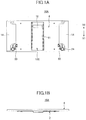
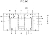
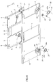
- FIGs. 1 through 4 are drawings used to describe a slide unit mechanism 10A according to a first embodiment.
- the slide unit mechanism 10A of the present embodiment includes a first fixed plate 1, a sliding plate 2, a second fixed plate 4, sliding torsion springs 5, and rattle preventing mechanisms 20.
- the slide unit mechanism 10A may be used, for example, for a portable electronic apparatus including an upper housing (monitor unit) that is slidable in the lateral direction relative to a lower housing (operation unit).
- the first and second fixed plates 1 and 4 are attached to a lower housing (not shown), and the sliding plate 2 is attached to an upper housing (not shown).
- the sliding plate 2 slides relative to the first and second fixed plates 1 and 4 in the lateral direction (directions indicated by arrows X1 an X2) of the first and second fixed plates 1 and 4.
- the upper housing slides relative to the lower housing between an open position and a closed position.
- the closed position indicates a position up to which the sliding plate 2 can slide in the X1 direction
- the open position indicates a position up to which the sliding plate 2 can slide in the X2 direction.
- the sliding plate 2 is at the closed position. Both the first fixed plate 1 and the sliding plate 2 have rectangular shapes (or quadrangular shapes in plan view). The area of the second fixed plate 4 is greater than the area of the first fixed plate 1 in front view.
- a protrusion 6 extending in the sliding direction (X1 and X2 directions) is formed in substantially the middle of the back surface of the first fixed plate 1.
- recesses 7 are formed (see FIG. 5 ).
- the sliding plate 2 is slidably attached to the first fixed plate 1.
- the sliding plate 2 includes slide parts 2a that slidably engage edge parts 8 located at the ends in the lateral direction of the first fixed plate 1 and a connecting part 2b that connects the slide parts 2a on the front surface (the side illustrated in FIGs. 1C and 2 ) of the first fixed plate 1.
- the slide parts 2a are folded backward from the connecting part 2b disposed on the front surface of the first fixed plate 1 and engage the edge parts 8 of the first fixed plate 1. Middle portions of the folded slide parts 2a further extend inward to form stoppers 3.
- the slide parts 2a are made of resin, and the connecting part 2b is made of metal.
- the slide parts 2a are formed by insert molding and are thereby combined with the connecting part 2b.
- the sliding plate 2 configured as described above slides on the first fixed plate 1 between the open position and the closed position.
- the slide unit mechanism 10A of the present embodiment is configured such that the sliding plate 2 slides in the lateral direction of the first and second fixed plates 1 and 4.
- the width (indicated by W in FIGs. 1C and 2 ) of the sliding plate 2 is set as short as possible but not to reduce the strength of the sliding plate 2.
- the first fixed plate 1 is attached to the second fixed plate 4 such that the sliding plate 2 is still slidable.
- a rectangular opening 11 is formed in the middle of the second fixed plate 4 to accommodate the protrusion 6 of the first fixed plate 1.
- a mounting recess 15, where the first fixed plate 1 is to be placed, is formed in the front surface of the second fixed plate 4 and thin parts 14 are formed in the back surface of the second fixed plate 4.
- Forming the thin parts 14 and the mounting recess 15 makes it possible to reduce the weight of the second fixed plate 4 that has a relatively large size. Also, it is possible to reduce the thickness of the slide unit mechanism 10A by placing the first fixed plate 1 in the mounting recess 15 of the second fixed plate 4.
- each of the stoppers 16 includes a metal plate 16a and a stopper rubber 16b that are stacked. As described above, the sliding plate 2 slides between the closed position and the open position. As illustrated in FIG. 5 , the stoppers 3 contact the stopper rubbers 16b of the stoppers 16 at the X1 end when the sliding plate 2 is at the closed position, and contact the stopper rubbers 16b of the stoppers 16 at the X2 end when the sliding plate 2 is at the open position. This configuration prevents the sliding plate 2 from sliding over the closed position and the open position.
- the sliding torsion springs 5 (which correspond to "sliding springs” in claims) are disposed in the recesses 7 formed on the right and left sides of the first fixed plate 1. One end of each of the sliding torsion springs 5 is held by a boss (not shown) formed substantially in the middle of the second fixed plate 4 in the sliding direction. The other end of the sliding torsion spring 5 is held by the stopper 3 of the slide part 2a.
- the winding part of the sliding torsion spring 5 is wound horizontally and has a flat shape. Using the sliding torsion spring 5 with the flat winding part instead of a torsion spring with a vertically-wound winding part makes it possible to reduce the thickness of the slide unit mechanism 10A.
- the sliding torsion springs 5 are disposed on the back surface of the first fixed plate 1.
- the sliding torsion springs 5 are positioned in a gap between the first fixed plate 1 and the second fixed plate 4. Accordingly, the sliding torsion springs 5 are not visible from the outside of the slide unit mechanism 10A.
- the slide unit mechanism 10A is configured as a semi-automatic sliding mechanism.
- a reference number 12 indicates an FPC hole.
- a flexible printed circuit (FPC) board is put through the FPC hole 12 to electrically connect a lower housing and an upper housing of the electronic apparatus.
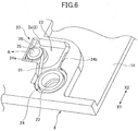
- Each of the rattle preventing mechanisms 20 includes a recess 21, an opening 23, a locking torsion spring 24, an engaging part 25, and an engaging recess 26.
- the rattle preventing mechanisms 20 prevent the sliding plate 2 from rattling when the sliding plate 2 is slid to the closed position.
- the recess 21 is formed in the back surface of the second fixed plate 4 near the closed position of the sliding plate 2.
- the locking torsion spring 24 and the engaging part 25 are placed in the recess 21. Accordingly, the locking torsion spring 24 and the engaging part 25 do not protrude from the back surface of the second fixed plate 4. That is, the rattle preventing mechanisms 20 do not increase the thickness of the slide unit mechanism 10A.
- a spring mounting boss 22 for mounting the locking torsion spring 24 is formed in the recess 21.
- the spring mounting boss 22 is formed as a monolithic part of the second fixed plate 4.
- the locking torsion spring 24 is placed in the recess 21 such that the spring mounting boss 22 is inserted in the opening of the winding part of the locking torsion spring 24.
- the opening 23 is also formed in the recess 21.
- the opening 23 passes through the second fixed plate 4 from the back surface to the front surface.
- the sliding plate 2 is slidably attached to the first fixed plate 1 and the first fixed plate 1 is attached to the second fixed plate 4.
- the position of the opening 23 on the front surface of the second fixed plate 4 is on the moving path of the slide part 2a. More specifically, the opening 23 is positioned to face the slide part 2a of the sliding plate 2 when the sliding plate 2 is at the closed position.
- the engaging part 25 is attached to an end 24a of the locking torsion spring 24. Another end 24b of the locking torsion spring 24 is disposed to contact the inner wall of the recess 21.
- the engaging part 25 is shaped like a roller and made of resin.
- the engaging part 25 may be made of polyacetal (POM) that is a type of engineering plastic with excellent shock resistance and sliding characteristics.
- the engaging part 25 protrudes from the opening 23 on the front surface of the second fixed plate 4.
- the engaging part 25 is positioned on the moving path of the slide part 2a and engages the slide part 2a of the sliding plate 2 when the sliding plate 2 is slid to the closed position.
- the engaging part 25 is biased outward (in the direction indicated by an arrow A in FIG. 6 ) by the elastic force of the locking torsion spring 24.
- the engaging recess 26 is formed in the slide part 2a of the sliding plate 2.
- the engaging recess 26 has a shape that matches the shape of the engaging part 25.
- the engaging recess 26 is formed at a side of the slide part 2a so as to face the engaging part 25 when the sliding plate 2 is moved to the closed position.
- the engaging part 25 engages the engaging recess 26 of the slide part 2a and is pressed against the engaging recess 26 by the elastic force of the locking torsion spring 24.
- two rattle preventing mechanisms 20 are provided across the sliding plate 2 at the closed position. Therefore, the sliding plate 2 is pressed from two sides by the engaging parts 25 that are biased by the elastic force of the locking torsion springs 24. In other words, the sliding plate 2 is sandwiched between a pair of rattle preventing mechanisms 20. Also, since the engaging parts 25 engage the engaging recesses 26, movement of the sliding plate 2 in the sliding direction (the X1 and X2 directions) is restricted. Thus, the rattle preventing mechanisms 20 make it possible to reliably prevent the sliding plate 2 at the closed position from rattling.
- the width W of the sliding plate 2 is reduced to increase the stroke length of the sliding plate 2
- the width of the slide parts 2a that engage the edge parts 8 is also reduced and the sliding plate 2 tend to rattle.
- the rattling of the sliding plate 2 at the closed position is prevented by the rattle preventing mechanisms 20 even when the width of the sliding plate 2 is short.
- the engaging part 25 engages the engaging recess 26 and thereby produces a "click" feel.
- the user of the slide unit mechanism 10A can recognize that the sliding plate 2 has reached the closed position based on this "click" feel.
- slide unit mechanisms 10B and 10C according to second and third embodiments are described with reference to FIGs. 7 and 8 .
- the same reference numbers as those used for the components of the slide unit mechanism 10A described with reference to FIGs. 1 through 6 are also used for the corresponding components in FIGs. 7 and 8 , and the descriptions of those components are omitted here.
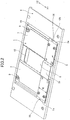
- FIG. 7 illustrates a slide unit mechanism 10B according to a second embodiment.
- the slide unit mechanism 10A of the first embodiment includes the rattle preventing mechanisms 20 that are disposed at the closed position of the sliding plate 2 to prevent the sliding plate 2 at the closed position from rattling.
- the slide unit mechanism 10B of the second embodiment includes rattle preventing mechanisms 20 at both the closed position and the open position of the sliding plate 2. This configuration makes it possible to prevent the sliding plate 2 from rattling at both the closed position and the open position. Also, although not shown, the rattle preventing mechanisms 20 may be provided only at the open position.
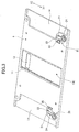
- FIG. 8 illustrates a first fixed plate 1 of a slide unit mechanism according to a third embodiment.
- the sliding torsion springs 5 are used as sliding springs.
- spring units 30 are used as sliding springs.
- the spring units 30 are disposed in the recesses 7 formed on the right and left sides of the first fixed plate 1.
- Each of the spring units 30 includes a middle part 31, a first slide part 32, a second slide part 33, first tension springs 34, and second tension springs 35.
- the first and second slide parts 32 and 33 are attached to the middle part 31 so as to be able to slide in the directions indicated by arrows Z1 and Z2 in FIG. 8 .
- the first tension springs 34 are extended between the first slide part 32 and the middle part
- the second tension springs 35 are extended between the second slide part 33 and the middle part 31.
- first slide part 32 is connected to the stopper 3 of the sliding plate 2, and one end of the second slide part 33 is connected to a boss (not shown) provided on the second fixed plate 4.
- the spring units 30 are disposed between the first fixed plate 1 and the second fixed plate 4 and are not visible from the outside of the slide unit mechanism.
- the sliding plate 2 is at the closed position.
- the spring unit 30 is caused to contract, the first slide part 32 is moved in the Z1 direction, and the second slide part 33 is moved in the Z2 direction.
- the first tension springs 34 and the second tension springs 35 are stretched, the first slide part 32 is biased in the Z2 direction, and the second slide part 33 is biased in the Z1 direction.
- the spring units 30 provide substantially the same functions as the sliding torsion springs 5 of the first embodiment, and the slide unit mechanism of the third embodiment is also configured as a semi-automatic sliding mechanism.
- the third embodiment makes it possible to reduce the thickness of the sliding unit mechanism.
- an engaging part of a rattle preventing mechanism engages an engaging recess formed in the sliding plate, and the engaging part is biased by elastic force of a locking torsion spring toward the engaging recess.
- the locking torsion spring and the engaging part constituting the rattle preventing mechanism are placed in a recess formed in a second fixed plate. This configuration makes it possible to reduce the thickness of the slide unit mechanism and to reduce the area of the slide unit mechanism that is exposed.
Landscapes
- Engineering & Computer Science (AREA)
- Theoretical Computer Science (AREA)
- Physics & Mathematics (AREA)
- Computer Hardware Design (AREA)
- Human Computer Interaction (AREA)
- General Engineering & Computer Science (AREA)
- General Physics & Mathematics (AREA)
- Signal Processing (AREA)
- Mathematical Physics (AREA)
- Microelectronics & Electronic Packaging (AREA)
- Computer Networks & Wireless Communication (AREA)
- Telephone Set Structure (AREA)
- Casings For Electric Apparatus (AREA)
Claims (2)
- Mécanisme d'unité coulissante pour un dispositif électronique portable, comprenant :une première plaque fixe quadrangulaire (1) comprenant une saillie formée au milieu d'une surface arrière de celle-ci suivant une direction de coulissement et des creux formés des deux côtés de la saillie ;une plaque coulissante (2) configurée pour coulisser sur la première plaque fixe (1) entre une position ouverte et une position fermée, la plaque coulissante (2) comprenant des pièces coulissantes (2a) mettant en prise de manière coulissante les bords de la première plaque fixe (1) et une pièce de connexion (2b) reliant les pièces coulissantes (2a) sur une surface avant de la première plaque fixe ;une deuxième plaque fixe (4) de dimension supérieure à la première plaque fixe, dans lequel la première plaque fixe (1) avec la plaque coulissante (2) rattachée à celle-ci est rattachée à la deuxième plaque fixe (4) ; etdes ressorts coulissants disposés dans les creux et entre la première plaque fixe (1) et la deuxième plaque fixe (4), les premières extrémités des ressorts coulissants étant maintenues dans des positions substantiellement au milieu de la première plaque fixe (1) dans la direction de coulissement, et les deuxièmes extrémités des ressorts coulissants étant maintenues par les pièces coulissantes (2a) ;caractérisé en ce qu'il comprend en outre des mécanismes anti-claquement (20) configurés pour mettre en prise la plaque coulissante (2) lorsque la plaque coulissante (2) est amenée à coulisser vers au moins l'une de la position ouverte et de la position fermée afin d'empêcher ainsi la plaque coulissante (2) de claquer,dans lequel chacun des mécanismes anti-claquement (20) comprendun creux (21) formé dans une surface arrière de la deuxième plaque fixe (4) dans une position correspondant à l'une de la position ouverte et de la position fermée de la plaque coulissante (2),une ouverture (23) qui passe par la deuxième plaque fixe (4) du creux (21) à une surface avant de la deuxième plaque fixe (4) et est positionnée sur un trajet d'une des pièces coulissantes (2a),un ressort de torsion de verrouillage (24) disposé dans le creux (21), une extrémité du ressort de torsion de verrouillage (24) mettant en prise la deuxième plaque fixe (4), et une autre extrémité du ressort de torsion de verrouillage (24) étant rattachée à une pièce de mise en prise (25) qui fait saillie de l'ouverture (23) sur le trajet de l'une des pièces coulissantes (2a), etun creux de mise en prise (26) formé dans l'une des pièces coulissantes (2a) et configuré pour mettre en prise la pièce de mise en prise (25) ;dans lequel la pièce de mise en prise (25) est configurée pour mettre en prise le creux de mise en prise (26) et pour être sollicitée par une force élastique du ressort de torsion de verrouillage (24) en direction du creux de mise en prise (26) lorsque la pièce coulissante (2) est amenée à coulisser vers la position ouverte ou la position fermée.
- Mécanisme d'unité coulissante selon la revendication 1, dans lequel les pièces coulissantes (2a) et la pièce de mise en prise (25) comprennent de la résine.
Applications Claiming Priority (2)
| Application Number | Priority Date | Filing Date | Title |
|---|---|---|---|
| JP2010129706A JP4865886B2 (ja) | 2010-06-07 | 2010-06-07 | スライドユニット機構 |
| PCT/JP2011/062689 WO2011155384A1 (fr) | 2010-06-07 | 2011-06-02 | Mécanisme pour module coulissant |
Publications (3)
| Publication Number | Publication Date |
|---|---|
| EP2579552A1 EP2579552A1 (fr) | 2013-04-10 |
| EP2579552A4 EP2579552A4 (fr) | 2014-01-01 |
| EP2579552B1 true EP2579552B1 (fr) | 2016-04-20 |
Family
ID=45097992
Family Applications (1)
| Application Number | Title | Priority Date | Filing Date |
|---|---|---|---|
| EP11792341.7A Active EP2579552B1 (fr) | 2010-06-07 | 2011-06-02 | Mécanisme pour module coulissant |
Country Status (6)
| Country | Link |
|---|---|
| US (1) | US8807835B2 (fr) |
| EP (1) | EP2579552B1 (fr) |
| JP (1) | JP4865886B2 (fr) |
| KR (1) | KR101419416B1 (fr) |
| CN (1) | CN102934416B (fr) |
| WO (1) | WO2011155384A1 (fr) |
Families Citing this family (4)
| Publication number | Priority date | Publication date | Assignee | Title |
|---|---|---|---|---|
| US9770871B2 (en) | 2007-05-22 | 2017-09-26 | The Boeing Company | Method and apparatus for layup placement |
| KR20150102489A (ko) * | 2014-02-28 | 2015-09-07 | 삼성전자주식회사 | 디스플레이 장치 |
| US11402878B2 (en) * | 2018-11-01 | 2022-08-02 | Lg Electronics Inc. | Display device |
| CN111664180A (zh) * | 2019-03-08 | 2020-09-15 | 安费诺飞凤(安吉)通信部品有限公司 | 一种铰链 |
Family Cites Families (14)
| Publication number | Priority date | Publication date | Assignee | Title |
|---|---|---|---|---|
| US5084884A (en) | 1989-08-04 | 1992-01-28 | Mitsui Petrochemical Industries, Ltd. | Method of stabilizing the laser beam and apparatus utilizing the same |
| JP3155691B2 (ja) | 1995-09-12 | 2001-04-16 | 矢崎総業株式会社 | 組付部品のロック構造 |
| BRPI0507769A (pt) * | 2004-02-10 | 2007-09-04 | Lee Han Sang | mecanismo de movimemnto e instrumento integrado com o mesmo |
| KR100630074B1 (ko) * | 2004-08-27 | 2006-09-27 | 삼성전자주식회사 | 휴대용 단말기의 슬라이딩 모듈 |
| KR100537698B1 (ko) | 2005-04-08 | 2005-12-20 | (주)쉘-라인 | 슬라이드 힌지장치, 개인휴대단말기 및 힌지장치의제조방법 |
| JP4845558B2 (ja) | 2006-03-29 | 2011-12-28 | 加藤電機株式会社 | 携帯機器 |
| US7853301B2 (en) * | 2006-09-19 | 2010-12-14 | Samsung Electronics Co., Ltd | Sliding module for double sliding-type portable communication terminal |
| JP2008196525A (ja) | 2007-02-08 | 2008-08-28 | Omron Corp | ヒンジ機構および携帯端末 |
| KR20100075443A (ko) * | 2007-10-26 | 2010-07-02 | 가부시키가이샤 스트로베리 코포레이션 | 슬라이드 장치 및 슬라이드 장치를 이용한 전자 기기 |
| JP4521489B2 (ja) * | 2008-03-27 | 2010-08-11 | 株式会社カシオ日立モバイルコミュニケーションズ | スライド機構及び電子機器 |
| CN101605439B (zh) | 2008-06-10 | 2012-03-14 | 鸿富锦精密工业(深圳)有限公司 | 滑动机构 |
| JP5329191B2 (ja) | 2008-11-27 | 2013-10-30 | 日置電機株式会社 | 吸着装置および検査装置 |
| JP3155691U (ja) * | 2009-09-15 | 2009-11-26 | 三菱製鋼株式会社 | スライドユニット |
| TWM387438U (en) * | 2010-03-31 | 2010-08-21 | Hon Hai Prec Ind Co Ltd | Sliding apparatus |
-
2010
- 2010-06-07 JP JP2010129706A patent/JP4865886B2/ja active Active
-
2011
- 2011-06-02 WO PCT/JP2011/062689 patent/WO2011155384A1/fr not_active Ceased
- 2011-06-02 CN CN201180028114.1A patent/CN102934416B/zh active Active
- 2011-06-02 EP EP11792341.7A patent/EP2579552B1/fr active Active
- 2011-06-02 US US13/701,901 patent/US8807835B2/en active Active
- 2011-06-02 KR KR1020127031892A patent/KR101419416B1/ko active Active
Also Published As
| Publication number | Publication date |
|---|---|
| US20130077903A1 (en) | 2013-03-28 |
| WO2011155384A1 (fr) | 2011-12-15 |
| EP2579552A1 (fr) | 2013-04-10 |
| US8807835B2 (en) | 2014-08-19 |
| JP4865886B2 (ja) | 2012-02-01 |
| KR20130024924A (ko) | 2013-03-08 |
| KR101419416B1 (ko) | 2014-07-14 |
| CN102934416A (zh) | 2013-02-13 |
| JP2011259059A (ja) | 2011-12-22 |
| CN102934416B (zh) | 2015-04-15 |
| EP2579552A4 (fr) | 2014-01-01 |
Similar Documents
| Publication | Publication Date | Title |
|---|---|---|
| KR100536939B1 (ko) | 슬라이드 타입 휴대용 단말기 | |
| EP2330803B1 (fr) | Dispositif électronique de type coulissant | |
| KR101733808B1 (ko) | 슬라이딩 타입 휴대용 통신 장치의 슬라이딩 모듈 | |
| US20100237550A1 (en) | Elastic member, slide device using the elastic member, and electric device using the slide device | |
| EP2579552B1 (fr) | Mécanisme pour module coulissant | |
| US20110237313A1 (en) | Mobile terminal apparatus | |
| EP2264986B1 (fr) | Dispositif électronique et mécanisme coulissant correspondant | |
| US8379396B2 (en) | Electronic device and connecting mechanism thereof | |
| KR100741014B1 (ko) | 휴대전화기용 슬라이딩 장치 | |
| JP5169945B2 (ja) | 情報端末装置 | |
| KR100800808B1 (ko) | 슬라이딩 타입 휴대 단말기의 슬라이딩 모듈 | |
| US8583196B2 (en) | Slide-type portable terminal | |
| JP5457589B2 (ja) | スライド式小型電子機器 | |
| KR101006046B1 (ko) | 휴대용 통신단말기를 개폐하기 위한 슬라이드 조립체 | |
| US7952867B2 (en) | Portable terminal having long stroke hinge | |
| JP4871931B2 (ja) | スライド式携帯端末 | |
| KR20100080501A (ko) | 휴대용 통신단말기를 개폐하기 위한 슬라이드 조립체 | |
| KR200439617Y1 (ko) | 슬라이드 타입 휴대용 단말기의 가이드 장치 | |
| KR100727074B1 (ko) | 슬라이드형 개인휴대단말기 | |
| JP2013197958A (ja) | スライド式携帯端末 | |
| KR20120064155A (ko) | 슬라이딩형 휴대용 단말기 | |
| JP2012065216A (ja) | 携帯端末 |
Legal Events
| Date | Code | Title | Description |
|---|---|---|---|
| PUAI | Public reference made under article 153(3) epc to a published international application that has entered the european phase |
Free format text: ORIGINAL CODE: 0009012 |
|
| 17P | Request for examination filed |
Effective date: 20121207 |
|
| AK | Designated contracting states |
Kind code of ref document: A1 Designated state(s): AL AT BE BG CH CY CZ DE DK EE ES FI FR GB GR HR HU IE IS IT LI LT LU LV MC MK MT NL NO PL PT RO RS SE SI SK SM TR |
|
| DAX | Request for extension of the european patent (deleted) | ||
| A4 | Supplementary search report drawn up and despatched |
Effective date: 20131204 |
|
| RIC1 | Information provided on ipc code assigned before grant |
Ipc: H04M 1/02 20060101AFI20131128BHEP Ipc: G06F 1/16 20060101ALI20131128BHEP |
|
| GRAP | Despatch of communication of intention to grant a patent |
Free format text: ORIGINAL CODE: EPIDOSNIGR1 |
|
| INTG | Intention to grant announced |
Effective date: 20151201 |
|
| GRAS | Grant fee paid |
Free format text: ORIGINAL CODE: EPIDOSNIGR3 |
|
| GRAA | (expected) grant |
Free format text: ORIGINAL CODE: 0009210 |
|
| RIN1 | Information on inventor provided before grant (corrected) |
Inventor name: MITSUI, YASUHIRO |
|
| AK | Designated contracting states |
Kind code of ref document: B1 Designated state(s): AL AT BE BG CH CY CZ DE DK EE ES FI FR GB GR HR HU IE IS IT LI LT LU LV MC MK MT NL NO PL PT RO RS SE SI SK SM TR |
|
| REG | Reference to a national code |
Ref country code: GB Ref legal event code: FG4D |
|
| REG | Reference to a national code |
Ref country code: CH Ref legal event code: EP |
|
| REG | Reference to a national code |
Ref country code: AT Ref legal event code: REF Ref document number: 793524 Country of ref document: AT Kind code of ref document: T Effective date: 20160515 |
|
| REG | Reference to a national code |
Ref country code: IE Ref legal event code: FG4D |
|
| REG | Reference to a national code |
Ref country code: DE Ref legal event code: R096 Ref document number: 602011025708 Country of ref document: DE |
|
| REG | Reference to a national code |
Ref country code: LT Ref legal event code: MG4D |
|
| REG | Reference to a national code |
Ref country code: AT Ref legal event code: MK05 Ref document number: 793524 Country of ref document: AT Kind code of ref document: T Effective date: 20160420 |
|
| REG | Reference to a national code |
Ref country code: NL Ref legal event code: MP Effective date: 20160420 |
|
| PG25 | Lapsed in a contracting state [announced via postgrant information from national office to epo] |
Ref country code: LT Free format text: LAPSE BECAUSE OF FAILURE TO SUBMIT A TRANSLATION OF THE DESCRIPTION OR TO PAY THE FEE WITHIN THE PRESCRIBED TIME-LIMIT Effective date: 20160420 Ref country code: NL Free format text: LAPSE BECAUSE OF FAILURE TO SUBMIT A TRANSLATION OF THE DESCRIPTION OR TO PAY THE FEE WITHIN THE PRESCRIBED TIME-LIMIT Effective date: 20160420 Ref country code: FI Free format text: LAPSE BECAUSE OF FAILURE TO SUBMIT A TRANSLATION OF THE DESCRIPTION OR TO PAY THE FEE WITHIN THE PRESCRIBED TIME-LIMIT Effective date: 20160420 Ref country code: NO Free format text: LAPSE BECAUSE OF FAILURE TO SUBMIT A TRANSLATION OF THE DESCRIPTION OR TO PAY THE FEE WITHIN THE PRESCRIBED TIME-LIMIT Effective date: 20160720 Ref country code: PL Free format text: LAPSE BECAUSE OF FAILURE TO SUBMIT A TRANSLATION OF THE DESCRIPTION OR TO PAY THE FEE WITHIN THE PRESCRIBED TIME-LIMIT Effective date: 20160420 |
|
| PG25 | Lapsed in a contracting state [announced via postgrant information from national office to epo] |
Ref country code: AT Free format text: LAPSE BECAUSE OF FAILURE TO SUBMIT A TRANSLATION OF THE DESCRIPTION OR TO PAY THE FEE WITHIN THE PRESCRIBED TIME-LIMIT Effective date: 20160420 Ref country code: SE Free format text: LAPSE BECAUSE OF FAILURE TO SUBMIT A TRANSLATION OF THE DESCRIPTION OR TO PAY THE FEE WITHIN THE PRESCRIBED TIME-LIMIT Effective date: 20160420 Ref country code: RS Free format text: LAPSE BECAUSE OF FAILURE TO SUBMIT A TRANSLATION OF THE DESCRIPTION OR TO PAY THE FEE WITHIN THE PRESCRIBED TIME-LIMIT Effective date: 20160420 Ref country code: PT Free format text: LAPSE BECAUSE OF FAILURE TO SUBMIT A TRANSLATION OF THE DESCRIPTION OR TO PAY THE FEE WITHIN THE PRESCRIBED TIME-LIMIT Effective date: 20160822 Ref country code: ES Free format text: LAPSE BECAUSE OF FAILURE TO SUBMIT A TRANSLATION OF THE DESCRIPTION OR TO PAY THE FEE WITHIN THE PRESCRIBED TIME-LIMIT Effective date: 20160420 Ref country code: LV Free format text: LAPSE BECAUSE OF FAILURE TO SUBMIT A TRANSLATION OF THE DESCRIPTION OR TO PAY THE FEE WITHIN THE PRESCRIBED TIME-LIMIT Effective date: 20160420 Ref country code: HR Free format text: LAPSE BECAUSE OF FAILURE TO SUBMIT A TRANSLATION OF THE DESCRIPTION OR TO PAY THE FEE WITHIN THE PRESCRIBED TIME-LIMIT Effective date: 20160420 Ref country code: GR Free format text: LAPSE BECAUSE OF FAILURE TO SUBMIT A TRANSLATION OF THE DESCRIPTION OR TO PAY THE FEE WITHIN THE PRESCRIBED TIME-LIMIT Effective date: 20160721 |
|
| PG25 | Lapsed in a contracting state [announced via postgrant information from national office to epo] |
Ref country code: IT Free format text: LAPSE BECAUSE OF FAILURE TO SUBMIT A TRANSLATION OF THE DESCRIPTION OR TO PAY THE FEE WITHIN THE PRESCRIBED TIME-LIMIT Effective date: 20160420 Ref country code: BE Free format text: LAPSE BECAUSE OF FAILURE TO SUBMIT A TRANSLATION OF THE DESCRIPTION OR TO PAY THE FEE WITHIN THE PRESCRIBED TIME-LIMIT Effective date: 20160420 |
|
| REG | Reference to a national code |
Ref country code: DE Ref legal event code: R097 Ref document number: 602011025708 Country of ref document: DE |
|
| PG25 | Lapsed in a contracting state [announced via postgrant information from national office to epo] |
Ref country code: DK Free format text: LAPSE BECAUSE OF FAILURE TO SUBMIT A TRANSLATION OF THE DESCRIPTION OR TO PAY THE FEE WITHIN THE PRESCRIBED TIME-LIMIT Effective date: 20160420 Ref country code: RO Free format text: LAPSE BECAUSE OF FAILURE TO SUBMIT A TRANSLATION OF THE DESCRIPTION OR TO PAY THE FEE WITHIN THE PRESCRIBED TIME-LIMIT Effective date: 20160420 Ref country code: CZ Free format text: LAPSE BECAUSE OF FAILURE TO SUBMIT A TRANSLATION OF THE DESCRIPTION OR TO PAY THE FEE WITHIN THE PRESCRIBED TIME-LIMIT Effective date: 20160420 Ref country code: SK Free format text: LAPSE BECAUSE OF FAILURE TO SUBMIT A TRANSLATION OF THE DESCRIPTION OR TO PAY THE FEE WITHIN THE PRESCRIBED TIME-LIMIT Effective date: 20160420 Ref country code: EE Free format text: LAPSE BECAUSE OF FAILURE TO SUBMIT A TRANSLATION OF THE DESCRIPTION OR TO PAY THE FEE WITHIN THE PRESCRIBED TIME-LIMIT Effective date: 20160420 Ref country code: MC Free format text: LAPSE BECAUSE OF FAILURE TO SUBMIT A TRANSLATION OF THE DESCRIPTION OR TO PAY THE FEE WITHIN THE PRESCRIBED TIME-LIMIT Effective date: 20160420 |
|
| REG | Reference to a national code |
Ref country code: CH Ref legal event code: PL |
|
| PLBE | No opposition filed within time limit |
Free format text: ORIGINAL CODE: 0009261 |
|
| STAA | Information on the status of an ep patent application or granted ep patent |
Free format text: STATUS: NO OPPOSITION FILED WITHIN TIME LIMIT |
|
| PG25 | Lapsed in a contracting state [announced via postgrant information from national office to epo] |
Ref country code: SM Free format text: LAPSE BECAUSE OF FAILURE TO SUBMIT A TRANSLATION OF THE DESCRIPTION OR TO PAY THE FEE WITHIN THE PRESCRIBED TIME-LIMIT Effective date: 20160420 |
|
| GBPC | Gb: european patent ceased through non-payment of renewal fee |
Effective date: 20160720 |
|
| REG | Reference to a national code |
Ref country code: IE Ref legal event code: MM4A |
|
| 26N | No opposition filed |
Effective date: 20170123 |
|
| REG | Reference to a national code |
Ref country code: FR Ref legal event code: ST Effective date: 20170228 |
|
| PG25 | Lapsed in a contracting state [announced via postgrant information from national office to epo] |
Ref country code: LI Free format text: LAPSE BECAUSE OF NON-PAYMENT OF DUE FEES Effective date: 20160630 Ref country code: CH Free format text: LAPSE BECAUSE OF NON-PAYMENT OF DUE FEES Effective date: 20160630 Ref country code: FR Free format text: LAPSE BECAUSE OF NON-PAYMENT OF DUE FEES Effective date: 20160630 |
|
| PG25 | Lapsed in a contracting state [announced via postgrant information from national office to epo] |
Ref country code: SI Free format text: LAPSE BECAUSE OF FAILURE TO SUBMIT A TRANSLATION OF THE DESCRIPTION OR TO PAY THE FEE WITHIN THE PRESCRIBED TIME-LIMIT Effective date: 20160420 Ref country code: GB Free format text: LAPSE BECAUSE OF NON-PAYMENT OF DUE FEES Effective date: 20160720 Ref country code: IE Free format text: LAPSE BECAUSE OF NON-PAYMENT OF DUE FEES Effective date: 20160602 |
|
| PG25 | Lapsed in a contracting state [announced via postgrant information from national office to epo] |
Ref country code: CY Free format text: LAPSE BECAUSE OF FAILURE TO SUBMIT A TRANSLATION OF THE DESCRIPTION OR TO PAY THE FEE WITHIN THE PRESCRIBED TIME-LIMIT Effective date: 20160420 Ref country code: HU Free format text: LAPSE BECAUSE OF FAILURE TO SUBMIT A TRANSLATION OF THE DESCRIPTION OR TO PAY THE FEE WITHIN THE PRESCRIBED TIME-LIMIT; INVALID AB INITIO Effective date: 20110602 |
|
| PG25 | Lapsed in a contracting state [announced via postgrant information from national office to epo] |
Ref country code: TR Free format text: LAPSE BECAUSE OF FAILURE TO SUBMIT A TRANSLATION OF THE DESCRIPTION OR TO PAY THE FEE WITHIN THE PRESCRIBED TIME-LIMIT Effective date: 20160420 Ref country code: MT Free format text: LAPSE BECAUSE OF NON-PAYMENT OF DUE FEES Effective date: 20160630 Ref country code: LU Free format text: LAPSE BECAUSE OF NON-PAYMENT OF DUE FEES Effective date: 20160602 Ref country code: MK Free format text: LAPSE BECAUSE OF FAILURE TO SUBMIT A TRANSLATION OF THE DESCRIPTION OR TO PAY THE FEE WITHIN THE PRESCRIBED TIME-LIMIT Effective date: 20160420 Ref country code: IS Free format text: LAPSE BECAUSE OF FAILURE TO SUBMIT A TRANSLATION OF THE DESCRIPTION OR TO PAY THE FEE WITHIN THE PRESCRIBED TIME-LIMIT Effective date: 20160420 |
|
| PG25 | Lapsed in a contracting state [announced via postgrant information from national office to epo] |
Ref country code: BG Free format text: LAPSE BECAUSE OF FAILURE TO SUBMIT A TRANSLATION OF THE DESCRIPTION OR TO PAY THE FEE WITHIN THE PRESCRIBED TIME-LIMIT Effective date: 20160420 |
|
| PG25 | Lapsed in a contracting state [announced via postgrant information from national office to epo] |
Ref country code: AL Free format text: LAPSE BECAUSE OF FAILURE TO SUBMIT A TRANSLATION OF THE DESCRIPTION OR TO PAY THE FEE WITHIN THE PRESCRIBED TIME-LIMIT Effective date: 20160420 |
|
| PGFP | Annual fee paid to national office [announced via postgrant information from national office to epo] |
Ref country code: DE Payment date: 20250429 Year of fee payment: 15 |