EP2579448A1 - Bestimmung der Rotorposition in sensorlosen geschalteten Reluktanzmotoren - Google Patents
Bestimmung der Rotorposition in sensorlosen geschalteten Reluktanzmotoren Download PDFInfo
- Publication number
- EP2579448A1 EP2579448A1 EP12187170.1A EP12187170A EP2579448A1 EP 2579448 A1 EP2579448 A1 EP 2579448A1 EP 12187170 A EP12187170 A EP 12187170A EP 2579448 A1 EP2579448 A1 EP 2579448A1
- Authority
- EP
- European Patent Office
- Prior art keywords
- signal
- feature
- rotor
- temporal derivative
- current
- Prior art date
- Legal status (The legal status is an assumption and is not a legal conclusion. Google has not performed a legal analysis and makes no representation as to the accuracy of the status listed.)
- Granted
Links
- 230000002123 temporal effect Effects 0.000 claims abstract description 87
- 238000004804 winding Methods 0.000 claims abstract description 57
- 238000000034 method Methods 0.000 claims abstract description 53
- 238000005070 sampling Methods 0.000 claims abstract description 16
- 238000001514 detection method Methods 0.000 claims description 15
- 238000012545 processing Methods 0.000 claims description 10
- 230000006870 function Effects 0.000 description 15
- XEEYBQQBJWHFJM-UHFFFAOYSA-N Iron Chemical compound [Fe] XEEYBQQBJWHFJM-UHFFFAOYSA-N 0.000 description 10
- 230000008901 benefit Effects 0.000 description 6
- 230000008859 change Effects 0.000 description 6
- 230000005291 magnetic effect Effects 0.000 description 6
- 238000005259 measurement Methods 0.000 description 6
- 230000001276 controlling effect Effects 0.000 description 5
- 229910052742 iron Inorganic materials 0.000 description 5
- 230000001419 dependent effect Effects 0.000 description 4
- 230000001939 inductive effect Effects 0.000 description 4
- 238000001914 filtration Methods 0.000 description 3
- 238000004364 calculation method Methods 0.000 description 2
- 238000010586 diagram Methods 0.000 description 2
- 230000005294 ferromagnetic effect Effects 0.000 description 2
- 230000004907 flux Effects 0.000 description 2
- 238000009499 grossing Methods 0.000 description 2
- 230000009467 reduction Effects 0.000 description 2
- 230000001105 regulatory effect Effects 0.000 description 2
- 230000004044 response Effects 0.000 description 2
- 229910000976 Electrical steel Inorganic materials 0.000 description 1
- 230000001133 acceleration Effects 0.000 description 1
- 230000003044 adaptive effect Effects 0.000 description 1
- 238000013459 approach Methods 0.000 description 1
- 238000013528 artificial neural network Methods 0.000 description 1
- 230000006399 behavior Effects 0.000 description 1
- 230000008878 coupling Effects 0.000 description 1
- 238000010168 coupling process Methods 0.000 description 1
- 238000005859 coupling reaction Methods 0.000 description 1
- 230000003247 decreasing effect Effects 0.000 description 1
- 230000000694 effects Effects 0.000 description 1
- 230000005672 electromagnetic field Effects 0.000 description 1
- 230000005662 electromechanics Effects 0.000 description 1
- 238000011156 evaluation Methods 0.000 description 1
- 230000010354 integration Effects 0.000 description 1
- 239000000696 magnetic material Substances 0.000 description 1
- 238000012544 monitoring process Methods 0.000 description 1
- 230000000630 rising effect Effects 0.000 description 1
- 230000001360 synchronised effect Effects 0.000 description 1
- 238000012546 transfer Methods 0.000 description 1
- 230000007704 transition Effects 0.000 description 1
- 230000001960 triggered effect Effects 0.000 description 1
Images

Classifications
-
- H—ELECTRICITY
- H02—GENERATION; CONVERSION OR DISTRIBUTION OF ELECTRIC POWER
- H02P—CONTROL OR REGULATION OF ELECTRIC MOTORS, ELECTRIC GENERATORS OR DYNAMO-ELECTRIC CONVERTERS; CONTROLLING TRANSFORMERS, REACTORS OR CHOKE COILS
- H02P6/00—Arrangements for controlling synchronous motors or other dynamo-electric motors using electronic commutation dependent on the rotor position; Electronic commutators therefor
- H02P6/14—Electronic commutators
- H02P6/16—Circuit arrangements for detecting position
- H02P6/18—Circuit arrangements for detecting position without separate position detecting elements
-
- H—ELECTRICITY
- H02—GENERATION; CONVERSION OR DISTRIBUTION OF ELECTRIC POWER
- H02P—CONTROL OR REGULATION OF ELECTRIC MOTORS, ELECTRIC GENERATORS OR DYNAMO-ELECTRIC CONVERTERS; CONTROLLING TRANSFORMERS, REACTORS OR CHOKE COILS
- H02P25/00—Arrangements or methods for the control of AC motors characterised by the kind of AC motor or by structural details
- H02P25/02—Arrangements or methods for the control of AC motors characterised by the kind of AC motor or by structural details characterised by the kind of motor
- H02P25/08—Reluctance motors
- H02P25/083—Arrangements for increasing the switching speed from one coil to the next one
-
- H—ELECTRICITY
- H02—GENERATION; CONVERSION OR DISTRIBUTION OF ELECTRIC POWER
- H02P—CONTROL OR REGULATION OF ELECTRIC MOTORS, ELECTRIC GENERATORS OR DYNAMO-ELECTRIC CONVERTERS; CONTROLLING TRANSFORMERS, REACTORS OR CHOKE COILS
- H02P25/00—Arrangements or methods for the control of AC motors characterised by the kind of AC motor or by structural details
- H02P25/02—Arrangements or methods for the control of AC motors characterised by the kind of AC motor or by structural details characterised by the kind of motor
- H02P25/08—Reluctance motors
- H02P25/086—Commutation
- H02P25/089—Sensorless control
-
- H—ELECTRICITY
- H02—GENERATION; CONVERSION OR DISTRIBUTION OF ELECTRIC POWER
- H02P—CONTROL OR REGULATION OF ELECTRIC MOTORS, ELECTRIC GENERATORS OR DYNAMO-ELECTRIC CONVERTERS; CONTROLLING TRANSFORMERS, REACTORS OR CHOKE COILS
- H02P6/00—Arrangements for controlling synchronous motors or other dynamo-electric motors using electronic commutation dependent on the rotor position; Electronic commutators therefor
- H02P6/14—Electronic commutators
- H02P6/16—Circuit arrangements for detecting position
- H02P6/18—Circuit arrangements for detecting position without separate position detecting elements
- H02P6/186—Circuit arrangements for detecting position without separate position detecting elements using difference of inductance or reluctance between the phases
Definitions
- the present invention relates to the field of switched reluctance motors. More specifically it relates to deriving commutation information in sensorless driven switched reluctance motors from a current profile, e.g. without prior knowledge of integral motor parameters such as inductance, resistance, flux linkage or inertia.
- a power stage provides a constant or variable current to opposite windings of the motor such that a ferromagnetic rotor, e.g. an iron rotor, moves to a position in which the inductance of the excited winding is maximized.
- a controller stage may calculate the position information of the iron rotor on one hand and provide control signals to the power stage on the other hand, e.g. a control signal triggered by a commutation point which may be determined by the position information.
- the rotor position information may be determined by a sensor-based method, e.g. from a discrete external sensing unit based on position sensors. This information may alternatively be determined by a sensorless method, e.g. by observing electric and/or magnetic parameters of the motor during motion of the rotor.
- Sensorless methods are known in the art which use flux integration, observer based methods, fuzzy logic, neural networks and/or induced voltage in order to estimate the mechanical rotor angle.
- Other known algorithms may rely on inductance based methods, in which the position may be reconstructed through analyzing an induced current waveform, which is a function of rotor angle and current.
- An example of such an inductance based method is disclosed in US 5,859,518 , which describes phase current commutation based on a threshold condition on the observed current.
- inductance is dependent on the rotor position, but also on the current itself.
- Sensorless methods based on inductance measurements may be known which handle this problem by complex look up tables.
- such approach may require an initial calibration of the system and/or detailed knowledge of mechanical, electric and/or magnetic parameters of the motor.
- a specific disadvantage of this method may be a tendency to react to noise, e.g. detection of zero current slope may be unreliable. Detection of onset of downward slope is suggested as an alternative. The robustness may be further increased by requiring a minimum of consecutive downward slope signals.
- US 6,979,974 describes a method for determining the position of a moving rotor of a reluctance motor.
- This method comprises applying a voltage to the phase winding having a waveform period independent from the period of rotor movement, e.g. applying voltage pulses during motor run; thus these voltage pulses provide current peaks in the motor current.
- the magnitude of the current peaks is influenced by the linked inductance and thus by the rotor position.
- This method comprises detecting a feature of the current waveform and deriving a position of the rotor from the occurrence of this feature.
- This feature may be a change of gradient of the current, for example the point of zero current slope di/dt.
- the present invention provides a method for determining the position of a moving rotor in a switched reluctance motor.
- the method comprises applying a voltage to a phase winding of the switched reluctance motor, sampling a signal representative of the current magnitude in said phase winding, detecting a feature of a second temporal derivative of said signal, and determining the position of the moving rotor taking into account the occurrence of said feature.
- said feature may comprise a zero crossing point of the second temporal derivative of said signal.
- the determining of the position of the moving rotor may comprise determining the sign of a third temporal derivative of said signal when the occurrence of said feature has been detected.
- the determining of the position of the moving rotor may comprise comparing a first temporal derivative of said signal when the occurrence of said feature has been detected to a reference value of the first temporal derivative of the signal.
- Said reference value may be an average of the first temporal derivative of the signal.
- determining the position of the moving rotor may comprise detecting an alignment of the moving rotor with said phase winding.
- a method according to embodiments of the present invention may furthermore comprise switching said voltage to a further phase winding of the reluctance motor when a predetermined position of the moving rotor has been determined.
- the present invention provides a device for determining the position of a moving rotor in a switched reluctance motor.
- the device comprises a current sensor for sampling a signal representative of the current magnitude in a phase winding of said switched reluctance motor while a voltage is applied to said phase winding, a feature detection unit for detecting a feature of a second temporal derivative of said signal, and a processing unit for determining the position of the moving rotor taking into account the occurrence of said feature.
- said current sensor may comprise an analog to digital converter for digitizing the current running through said phase winding.
- said feature detection unit may comprise a filter for calculating said second temporal derivative of the signal.
- said feature detection unit may comprise a zero-crossing detector for detecting said feature, said feature being a zero-crossing event of the second temporal derivative of said signal.
- a device may furthermore comprise a memory unit for storing a sequence of samples of said signal and/or second temporal derivatives of said signal.
- a device may furthermore comprise a power stage for powering said switched reluctance motor, and the processing unit may be adapted for generating a commutation signal for controlling said power stage.
- the present invention provides a system comprising a switched reluctance motor comprising a rotor and a device according to embodiments of the second aspect of the present invention for determining the position of said rotor in motion.
- the present invention relates to a method for determining the position of a moving rotor in a reluctance motor.
- This method comprises the step of applying a voltage to a phase winding of the reluctance motor.
- the method further comprises sampling a signal representative of the current magnitude in the phase winding and detecting a feature of the second temporal derivative of this signal.
- the method furthermore comprises the step of determining the position of the moving rotor taking into account the occurrence of this feature.
- a method 1 for determining the position of a moving rotor in a reluctance motor for example a switched reluctance motor, e.g. a switched reluctance motor operating in a medium speed range
- a medium speed range may correspond to operation of the motor, e.g. when a stable hysteresis regime is established, e.g. after an initial start-up phase of the motor (e.g. rotor alignment to the stator field and rotor acceleration), but operation at a moderate speed such that, for example, back electromotive force contributions and fast heat-induced resistive changes may be neglected in modeling the electro-mechanic behavior of the motor.
- This reluctance motor may be an electric motor that comprises a rotatably mounted ferromagnetic rotor, e.g. an iron rotor or a rotor made of a soft magnetic material, such as laminated silicon steel.
- the rotor may also comprise multiple protrusions, e.g. for providing salient magnetic poles through magnetic reluctance.
- the motor further may comprise a stator having multiple stator poles with phase windings, e.g. electric windings for inducing a non-permanent magnetic field in the iron rotor along multiple directions corresponding to the stator pole orientations. While these electric windings may be electrically coupled in a predetermined manner, such as in synchronous reluctance motors, the stator poles may also be electrically insulated and separately controllable, such as in switched reluctance motors.
- the number of protrusions on the rotor may typically be different from the number of stator poles in order to minimize torque ripple and for preventing complete alignment of the rotor protrusions and the stator poles.
- a partial alignment remains however possible, e.g. in which two or more rotor protrusions completely face two or more stator poles.
- Such partial alignment which may simply be referred to as an "aligned position" corresponds to a position of minimum reluctance of the motor.
- a switched reluctance motor provides electronic commutation, e.g. switching of the active windings of the stator poles, in order to achieve a desired operational mode, e.g. a desired rotation sense and/or a speed preference, and a smooth torque coupling.
- a desired operational mode e.g. a desired rotation sense and/or a speed preference
- a smooth torque coupling In order to achieve a full rotation of the motor, the windings need to be energized sequentially corresponding to a timing tuned to the position of the rotor.
- the method 1 comprises the step of applying 2 a voltage to a phase winding of the reluctance motor.
- the phase voltage may be maintained at a predetermined voltage level, e.g. a reference supply voltage, or the phase voltage may be regulated in a controlled manner, for example, may be ramped up or ramped down, e.g. following a linear transition as function of time from a first voltage level, e.g. an electrical ground, to a second voltage level, e.g. a reference supply voltage.
- the phase voltage may be regulated in a more complex manner, e.g. following a non-linear predetermined function of time.
- the method 1 may furthermore comprise the step of switching this voltage to a further phase winding of the reluctance motor when a predetermined position of the moving rotor has been determined 5, e.g. as discussed further herein.
- the voltage on this phase winding may be switched off and a voltage may be applied to a further phase winding, e.g. the next phase winding in the direction of rotation of the rotor.
- the voltage on the first phase winding may be gradually decreased, e.g. ramped down, while the voltage on the next phase winding may be gradually increased, e.g. ramped up, such that a smooth rotation of the motor may be achieved.
- the method 1 further comprises sampling 3 a signal representative of the current magnitude in the phase winding, e.g. the phase winding to which a voltage is applied 2.
- a analog to digital converter may be electrically coupled to the phase winding in order to obtain a measurement signal or plurality of measurement signals charactering the current magnitude.
- Such signal representative of the current magnitude may be derived from the current intensity or electrical power running through the phase winding.
- the sampling may for example be performed at a frequency, that is directly proportional to the electrical motor speed and the requested resolution. E.g. for a switched reluctance motor with 5000 rpm and a rotor with 14 teeth and a resolution of 100 samples per electrical revolution, the sampling rate may e.g. be 116 kHz.
- this signal may be filtered, e.g. in order to reduce the influence of noise, for example, by means of a low pass filter to exclude high frequency noise, e.g. at frequencies higher than the frequency of phase commutation.
- the method 1 also comprises detecting 4 a feature of the second temporal derivative of this signal.
- This detecting 4 of the feature may comprise determining the second temporal derivative of the signal, for example, by calculating a second order finite difference approximation for the second derivative applied on the signal, e.g. a backward second order difference applied to the current signal sample and a plurality of previous signal samples stored in a memory, e.g. applied to the at least three most recent signal samples.
- this determining of the second temporal derivative may be combined with filtering operations, e.g. for noise reduction as described hereinabove in relation to the sampling 3.
- a second order finite difference may be combined by an appropriate discrete implementation for smoothing the signal, e.g. a discrete filter determined by convolving a Gaussian smoothing kernel with a second order derivative operator.
- the feature may comprise the zero-crossing point of the second temporal derivative of the signal.
- the zero-crossing point of this second temporal derivative may correspond to either the maximum or the minimum of the first temporal derivative of the phase current, e.g. the phase current slope.
- this maximum or minimum of the phase current slope furthermore may correspond in good approximation to respectively the minimum or the maximum of the inductance, and hence to respectively an unaligned or an aligned position of the rotor.
- This feature may furthermore be detected in a robust manner such that noise effects can be reduced, for example, by evaluating a number of samples in a time window.
- the feature may comprise comparing a value of the second temporal derivative to a threshold value, such that a zero-crossing is assumed when the second temporal derivative is smaller than this threshold value, for example, a small fraction of an average, maximum or dynamic range of the second temporal derivative, e.g. a threshold of 1% thereof.
- the method 1 furthermore comprises the step of determining 5 the position of the moving rotor taking into account the occurrence of this feature. Determining 5 the position of the moving rotor may include determining whether the rotor is in a predetermined position, for example an aligned or unaligned position. Determining 5 the position of the moving rotor may also include determining a current location and speed of the rotor, e.g. in order to enable accurate modeling and prediction of the movement of the rotor.
- An occurrence of the feature e.g. the zero-crossing of the second temporal derivative of the signal
- determining 5 the position may comprise taking into account the sign of the third temporal derivative of the signal at the moment of occurrence of the feature. For example, if this third derivative is positive, the rotor position may be determined to be an aligned position, e.g. the aligned position corresponding to the current phase winding being supplied 2.
- the first temporal derivative of the signal may be compared to an average value of this first temporal derivative of the signal. For example, if the first temporal derivative of the signal is larger than this average, the zero-crossing of the second temporal derivative may correspond to a maximum of the first temporal derivative, and therefore the position of the rotor may be determined to be in an unaligned position. Calculating such average may comprise calculating (slope max +slope min )/2, in which slope max corresponds to a maximum of the first temporal derivative of the signal and slope min to a minimum of the first temporal derivative of the signal.
- the last two values of the first temporal derivative of the signal observed on detecting the last two occurrences of the feature may be stored, and an average value for the first temporal derivative of the signal may be updated based on these two previous values, e.g. for comparing to a new value of the first temporal derivative of the signal when detecting the next occurrence of the feature. It is an advantage of such repeated calculation, e.g. continuous updates, of this average value, that the influence of noise and inaccurate measurements may be reduced and that changes to the average value over time, e.g. due to the dependence of the inductance on the current, may be compensated accordingly.
- such running average may be a weighted average, e.g. assigning a weight to each of the previous values, for example, such that the relative contribution of older values is reduced.
- determining 5 the position of the rotor may comprise determining a time interval between occurrences of this feature, e.g. a time interval between two zero-crossings of the second temporal derivative of the signal, for example a time interval between two, successive zero-crossings.
- This time interval may be used to determine the angular velocity of the rotor, which may be used to accurately determine the position of the rotor as function of time, e.g. taking into account a lapsed time interval for sampling and processing, and/or to predict the position of the rotor at a future point in time, e.g. when a reference position, such as an aligned or unaligned position, has been determined such as described hereinabove.
- a complex commutation scheme may be implemented, e.g. a phase voltage to be applied to the phase windings in function of rotor position, in which this rotor position does not necessarily correspond to an aligned or unaligned position.
- a angular position between an unaligned and an aligned position may be defined for starting a decrease of the voltage applied over the currently active phase winding and/or starting an increase of the voltage to be applied over the next phase winding to become active.
- the angular velocity may be substantially constant, for example changes by less than 5%, e.g. less than 1%, or even less than 0.1%, from one period to the next, e.g. in passing from one aligned position of the rotor to the next aligned position of the rotor. Therefore, a rotor position estimate may be continuously updated taking into account the angular velocity, e.g. determined by measuring a time interval between recent occurrences of the feature, and the most recent aligned and/or unaligned position of the rotor, e.g. as determined by point in time of a recent occurrence of the feature. Moreover, estimation errors may only accumulate over a single commutation period, as both the velocity and the reference position, e.g. aligned or unaligned position, may be updated in each commutation period.
- the method 1 may furthermore comprise the step of switching 6 the voltage to a further phase winding of the reluctance motor when a predetermined position of the moving rotor has been determined.
- the method 1 may comprise executing a phase commutation event in response to the determined position, e.g. when an aligned position has been detected.
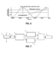
- FIG. 7 an exemplary control diagram for a reluctance motor according to embodiments of the present invention is shown.
- a signal representative of the current magnitude in a currently active phase winding of a reluctance motor is sampled 3, e.g. a current is sensed.
- This signal may be filtered, e.g. in order to compensate measurement noise in the signal.
- the filtered signal may then be used to calculate 8 a derivative of the signal, e.g. to calculate a second temporal derivative.
- the first temporal derivative and/or the third temporal derivative may also be calculated.
- a feature of the second temporal derivative is then detected 4, for example a zero-crossing of the second temporal derivative of the signal.
- a position of the rotor is furthermore determined 5 taking into account the occurrence of this feature. This may involve an evaluation 7 of the first or third derivative as described hereinabove, e.g. evaluating a zero-crossing event selection criterion in order to select an occurrence of this feature which corresponds to a specific position of the rotor such as an aligned position. Finally, a commutation event for the motor 15 may be generated, e.g. the applied voltage may be switched 6 to a next phase winding in response to the determined position of the rotor.
- the present invention relates in a second aspect to a device 10 for determining the position of a moving rotor in a reluctance motor 15.
- a device 10 for determining the position of a moving rotor in a reluctance motor 15.
- Such device 10 comprises a current sensor 11 for sampling a signal representative of the current magnitude in a phase winding of the reluctance motor 15 while a voltage is applied to this phase winding, e.g. for sampling a signal representative of the current magnitude in a currently active phase winding of the reluctance motor 15.
- the device 10 furthermore comprises a feature detection unit 12 for detecting a feature of the second temporal derivative of said signal, and a processing unit 13 for determining the position of the moving rotor taking into account the occurrence of this feature.
- the device 10 according to embodiments of the present invention may be adapted for implementing a method according to the first aspect of the present invention.
- the current sensor 11 may comprise an analog to digital converter 18 for digitizing the current running through the phase winding.
- the feature detection unit 12 may comprise a filter for calculating the second temporal derivative of the signal, for example a finite differencing unit for calculating a discrete approximation to the second temporal derivative of the signal.
- This filter may furthermore be adapted for filtering out a noise component in this signal, for example, high frequency noise corresponding to frequencies above the expected dynamic range of the information content in the signal. This noise filtering may be provided in accordance with a maximum speed of the motor 15 in normal operation.
- the filter may additionally provide the first and/or the third temporal derivative of the signal, e.g. store these values in a memory unit 16, for example such that these values may be provided to the processing unit 13.
- the feature detection unit 12 may furthermore comprise a zero-crossing detector for detecting the feature, in which this feature is a zero-crossing event of the second temporal derivative of the signal.
- this zero-crossing detector may detect a change of sign of the second temporal derivative of the signal.
- the device 10 may furthermore comprise a memory unit 16 for storing a sequence of samples of the signal and/or the second temporal derivatives of the signal.
- values provided by the analog to digital converter 18 may be stored in a buffer, e.g. such that a list of most recent values are maintained in memory.
- These stored values may be provided to the feature detection unit 12, e.g. to a filter component thereof, for calculating the second temporal derivative of the signal.
- This second temporal derivative may also be stored in memory, or directly provided to the zero-crossing detector for deciding whether the feature has occurred, e.g. whether a zero-crossing of the second temporal derivative of the signal has occurred.
- a sequence of stored second temporal derivatives e.g.
- ⁇ stored in memory, may be used to provide a more robust detection of zero-crossings, e.g. when a zero-crossing has been detected in a previous sampling point, e.g. time instance, the following sampling point, e.g. time instance, may be evaluated to confirm the zero-crossing.
- the processing unit 13 may be adapted for determining the sign of the third temporal derivative of the signal when the occurrence of the feature has been detected. For example, when the sign of the third temporal derivative is established to be positive, the position of the rotor of the reluctance motor 15 may be determined to be an aligned position, e.g. corresponding to the aligned position of the currently active phase winding. Similarly, when the sign of the third temporal derivative is established to be negative, the position of the rotor may be determined to be an unaligned position, e.g. corresponding to the unaligned position between the currently active phase winding and the phase winding which was previously active during a previous commutation phase of the motor.
- the processing unit 13 may be adapted for comparing the first temporal derivative of the signal to an average value of this first temporal derivative of the signal.
- a mean value for the first temporal derivative of the signal may be continuously updated, e.g. calculated for the previous two occurrences of the feature, or for the previous four occurrences of the feature, and the current value of the first temporal derivative may be compared to this calculated mean value. If the current value is greater than this mean value, the position of the rotor may be determined to be an unaligned position, while if this current value is smaller than the mean value, the position of the rotor may be determined to be an aligned position.
- a current value of the first temporal derivative e.g. when the feature has been detected, may be compared to a previous version of the first temporal derivative, e.g. stored on the previous occurrence of the feature, and the position may be determined to be aligned when this current value is smaller than the previous value, or unaligned when this current value is greater than the previous value.
- a larger number of previous values may be used to determine the mean value for the first temporal derivative of the signal, e.g. in order to provide a more robust determination of the position of the rotor. This may be advantageous when the amplitude of this first temporal derivative over time is small, e.g. comparable to the amplitude of noise present in this first temporal derivative.
- the device 10 may furthermore comprise a power stage 17 for powering the reluctance motor 15.
- the processing unit 13 may be adapted for generating a commutation signal for controlling the power stage 17, e.g. for controlling a transfer of applied voltage from one phase winding to a next phase winding of the reluctance motor 15.
- the present invention relates to a system comprising a reluctance motor 15, which comprises a rotor, and a device 10 according to the second aspect of the present invention.
- the inductance L d ( ⁇ , i p ) can be qualitatively be described as a trigonometric function of rotor position in time and the current, e.g. a sinusoid, which is transposed upward relative to the zero inductance axis, e.g. positively biased. This vertical shift can be determined by calculating the mean value of the extrema of this function. Since the current slope, e.g. the first temporal derivative of the phase current, is qualitatively similar to, but inversed with respect to, the inductance, information about the position of the rotor may be gained from the average current slope, e.g. di p dt max + di p dt min 2 , and the current slope amplitude, e.g. the half amplitude of the current slope di p dt max - di p dt min 2 . .
- a Current Sensing device 4 provides motor current information over time.
- the sensing might be done with an AD converter.
- the current information over time might be stored in a memory.
- a Filter 5 might provide the motor current information.
- the voltage u p which is applied on a phase winding can be represented as the sum of a resistive part u Ohm and an inductive part u ind :
- u indMotion due to a changing position of the rotor is known as a counter-electromotive force or back electromotive force (BEMF).
- the inductance also changes as function of the current, it can be seen from u indMotion that, for a constant supply voltage u p , a qualitative relation between the inductance L d ( ⁇ , i p ) and the first temporal derivative of the current ⁇ i p ⁇ t exists on the rising and falling flanks of the phase current, e.g. when the temporal derivative of the current ⁇ i p ⁇ t dominates the current i p . For example, when the current slope becomes more steep, the inductance becomes smaller. Therefore, information about the actual position of the rotor may be gained by observing the extrema of the first derivative of the current.
- the time intervals between the zero crossings of the second temporal derivative of the current may be used to determine the position.
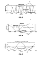
- the inductance of the motor seen from one phase for a rotating rotor is shown in FIG. 3 .
- a maximum inductance 42 is equivalent to an optimal alignment of the stator pole with the corresponding rotor pole, e.g. an aligned position. Because of the fact that the rate in change of phase current is qualitative similar to the inverse inductance trend, it is possible to find the inductance maximum 42 of a phase, and hence an aligned position, in accordance with embodiments of the present invention, by looking for the phase current slope's minimum. Because the inductance is approximately following a trigonometric function, the current slope will follow a similar trigonometric function too.
- the phase current slope d ⁇ i p dt is given as the first temporal derivative of the phase current.
- An exemplary current slope trace is shown in FIG. 4 . It is to be noted, that only the point of the local current slope's minimum 44 may be point of interest.
- An exemplary second temporal derivative d 2 ⁇ i p dt 2 of the motor phase current, thus the first temporal derivative of the phase current slope, is shown in FIG. 5 .
- the local maximum 43 or minimum 44 of the phase current slope di p dt now corresponds with the Zero Crossing Events 45 of the second temporal derivative of the motor phase current.
- the right Zero Crossing Event for the commutation information, e.g.
- selection criteria may be applied according to embodiments of the present invention. For example, such selection may take the second derivative of the current slope into account, e.g. the third temporal derivative of the phase current, of which an exemplary trace is shown in FIG. 6 .
- Embodiments of the present invention are able to operate a switched reluctance motor just by observation of the 2nd derivative of the motor current and a self adaptive criterion to select the correct timing event to generate the information for the motor commutation. It may not be needed to know any specific motor parameters. It may also not be needed to work with difficult threshold conditions.
- the method provided by embodiments of the present invention may be self adapting, so that there is also no need to build up any fixed threshold setting for generation of the motor commutation.
- a position of a moving rotor in a reluctance motor may be determined based only on the measurement of the current phase current. Since the inductance is a function of the current and rotor position, this property can be used to make a statement about the state of the rotor.
- the current slope may not only be a function of the rotor position but also a function of the current itself. Generating and using a lookup table to get information for every specific angle/current-combination in order to extract the rotor position information may be cumbersome. However, by a method according to embodiments of the present invention, no such lookup table may be required.
Landscapes
- Engineering & Computer Science (AREA)
- Power Engineering (AREA)
- Control Of Electric Motors In General (AREA)
Applications Claiming Priority (2)
| Application Number | Priority Date | Filing Date | Title |
|---|---|---|---|
| US201161542978P | 2011-10-04 | 2011-10-04 | |
| GB1206590.0A GB2501129A (en) | 2012-04-13 | 2012-04-13 | Determining rotor position in sensorless switched reluctance motors |
Publications (2)
| Publication Number | Publication Date |
|---|---|
| EP2579448A1 true EP2579448A1 (de) | 2013-04-10 |
| EP2579448B1 EP2579448B1 (de) | 2014-02-12 |
Family
ID=46209076
Family Applications (1)
| Application Number | Title | Priority Date | Filing Date |
|---|---|---|---|
| EP12187170.1A Active EP2579448B1 (de) | 2011-10-04 | 2012-10-04 | Bestimmung der Rotorposition in sensorlosen geschalteten Reluktanzmotoren |
Country Status (3)
| Country | Link |
|---|---|
| US (1) | US9059651B2 (de) |
| EP (1) | EP2579448B1 (de) |
| GB (1) | GB2501129A (de) |
Cited By (2)
| Publication number | Priority date | Publication date | Assignee | Title |
|---|---|---|---|---|
| WO2014174339A1 (en) * | 2013-04-22 | 2014-10-30 | Freescale Semiconductor, Inc. | Method, computer program product and controller for starting-up a switched reluctance motor, and electrical apparatus implementing same |
| CN109728569A (zh) * | 2018-12-20 | 2019-05-07 | 上海广吉电气有限公司 | 转子式智能高压开关 |
Families Citing this family (10)
| Publication number | Priority date | Publication date | Assignee | Title |
|---|---|---|---|---|
| US20130207588A1 (en) * | 2012-02-15 | 2013-08-15 | Samsung Electro-Mechanics Co., Ltd. | Initial driving apparatus and method of two-phase srm |
| EP2712075B1 (de) * | 2012-09-20 | 2018-03-07 | Perkins Engines Company Limited | Verfahren zur Steuerung einer geschalteten Reluktanzmaschine |
| US9722517B2 (en) | 2014-04-01 | 2017-08-01 | Mcmaster University | Systems and methods for rotor position determination |
| US10581274B2 (en) | 2015-06-03 | 2020-03-03 | Lg Electronics Inc. | Home appliance |
| KR101698775B1 (ko) * | 2015-08-11 | 2017-01-23 | 엘지전자 주식회사 | 홈 어플라이언스 |
| KR101663520B1 (ko) * | 2015-08-11 | 2016-10-07 | 엘지전자 주식회사 | 모터 구동장치 및 이를 구비하는 홈 어플라이언스 |
| US10236808B2 (en) * | 2016-08-25 | 2019-03-19 | Analog Devices, Inc. | Systems and methods for determining motor parameters |
| US10236815B2 (en) * | 2016-12-02 | 2019-03-19 | Arm Ltd. | Sensor error detection and correction |
| US10987784B2 (en) * | 2018-02-23 | 2021-04-27 | Ingersoll-Rand Industrial U.S., Inc. | Cordless impact tool with brushless, sensorless, motor and drive |
| CN110212820B (zh) * | 2019-06-05 | 2021-01-19 | 南京航空航天大学 | 六状态提前角度控制的电励磁双凸极电机带载起动方法 |
Citations (5)
| Publication number | Priority date | Publication date | Assignee | Title |
|---|---|---|---|---|
| US5793179A (en) | 1995-12-19 | 1998-08-11 | Switched Reluctance Drives Limited | Sensorless rotor position monitoring in reluctance machines |
| US5859518A (en) | 1997-12-22 | 1999-01-12 | Micro Linear Corporation | Switched reluctance motor controller with sensorless rotor position detection |
| US20010010452A1 (en) * | 1999-12-15 | 2001-08-02 | Switched Reluctance Drives Limited | Rotor position monitoring of a reluctance drive |
| US20040212359A1 (en) * | 2003-04-24 | 2004-10-28 | Switched Reluctance Drives Limited | Rotor position determination in a switched reluctance machine |
| EP1526635A2 (de) * | 2003-10-22 | 2005-04-27 | Fanuc Ltd | Detektionseinrichtung, und -verfahren zur Detektion der Position von Magnet-Polen |
Family Cites Families (16)
| Publication number | Priority date | Publication date | Assignee | Title |
|---|---|---|---|---|
| US4477757A (en) * | 1983-02-21 | 1984-10-16 | Dataproducts Corporation | Phase commutator for closed loop control of a stepping motor |
| US5537308A (en) * | 1993-10-15 | 1996-07-16 | Eaton Corporation | Digital current regulator |
| US6225769B1 (en) * | 1994-06-07 | 2001-05-01 | Veit-Michael Brenner | Device for operating an electric motor |
| US5949210A (en) * | 1998-03-16 | 1999-09-07 | Lockheed Martin Corp. | Two-dimensional variable limit proportional internal regulator for the current controller in synchronous frame |
| US6014006A (en) * | 1999-06-24 | 2000-01-11 | Ford Global Technologies, Inc. | Induction motor control system with speed and flux estimation |
| US6229278B1 (en) * | 1999-09-29 | 2001-05-08 | Rockwell Technologies, Llc | Voltage and current limiting method and apparatus for a voltage/frequency drive |
| DE10061563B4 (de) * | 2000-12-06 | 2005-12-08 | RUBITEC Gesellschaft für Innovation und Technologie der Ruhr-Universität Bochum mbH | Verfahren und Vorrichtung zum Ein- und Ausschalten von Leistungshalbleitern, insbesondere für ein drehzahlvariables Betreiben einer Asynchronmaschine, ein Betreiben einer Zündschaltung für Ottomotoren, sowie Schaltnetzteil |
| GB0221117D0 (en) * | 2002-09-12 | 2002-10-23 | Black & Decker Inc | Control of electrical machines |
| EP1463194A1 (de) * | 2003-03-11 | 2004-09-29 | Japan Servo Co. Ltd. | Schrittmotorantrieb |
| GB0312848D0 (en) * | 2003-06-04 | 2003-07-09 | Switched Reluctance Drives Ltd | Rotor position detection of a switched reluctance drive |
| US6959969B2 (en) * | 2004-03-05 | 2005-11-01 | Delphi Technologies, Inc. | System and method for controlling a brake |
| US20050263330A1 (en) * | 2004-05-28 | 2005-12-01 | Valeo Electrical Systems, Inc. | Field-oriented control for brushless DC motor |
| US7444248B2 (en) * | 2005-04-29 | 2008-10-28 | General Electric Company | System and method for synchronized phasor measurement |
| JP4320743B2 (ja) * | 2007-03-02 | 2009-08-26 | 株式会社デンソー | 回転機の制御装置 |
| GB2455122A (en) * | 2007-11-29 | 2009-06-03 | Technelec Ltd | Control of electrical machines |
| JP5263024B2 (ja) * | 2009-06-18 | 2013-08-14 | 株式会社日立製作所 | 回転角検出装置および回転速度検出装置 |
-
2012
- 2012-04-13 GB GB1206590.0A patent/GB2501129A/en not_active Withdrawn
- 2012-10-04 EP EP12187170.1A patent/EP2579448B1/de active Active
- 2012-10-04 US US13/644,539 patent/US9059651B2/en active Active
Patent Citations (7)
| Publication number | Priority date | Publication date | Assignee | Title |
|---|---|---|---|---|
| US5793179A (en) | 1995-12-19 | 1998-08-11 | Switched Reluctance Drives Limited | Sensorless rotor position monitoring in reluctance machines |
| US5859518A (en) | 1997-12-22 | 1999-01-12 | Micro Linear Corporation | Switched reluctance motor controller with sensorless rotor position detection |
| US20010010452A1 (en) * | 1999-12-15 | 2001-08-02 | Switched Reluctance Drives Limited | Rotor position monitoring of a reluctance drive |
| US6586903B2 (en) | 1999-12-15 | 2003-07-01 | Switched Reluctance Drives Ltd. | Rotor position monitoring of a reluctance drive |
| US20040212359A1 (en) * | 2003-04-24 | 2004-10-28 | Switched Reluctance Drives Limited | Rotor position determination in a switched reluctance machine |
| US6979974B2 (en) | 2003-04-24 | 2005-12-27 | Switched Reluctance Drives Limited | Rotor position determination in a switched reluctance machine |
| EP1526635A2 (de) * | 2003-10-22 | 2005-04-27 | Fanuc Ltd | Detektionseinrichtung, und -verfahren zur Detektion der Position von Magnet-Polen |
Cited By (6)
| Publication number | Priority date | Publication date | Assignee | Title |
|---|---|---|---|---|
| WO2014174339A1 (en) * | 2013-04-22 | 2014-10-30 | Freescale Semiconductor, Inc. | Method, computer program product and controller for starting-up a switched reluctance motor, and electrical apparatus implementing same |
| CN105144571A (zh) * | 2013-04-22 | 2015-12-09 | 飞思卡尔半导体公司 | 启动开关磁阻电机的方法、计算机程序产品和控制器以及实施其的电装置 |
| CN105144571B (zh) * | 2013-04-22 | 2017-05-17 | 飞思卡尔半导体公司 | 启动开关磁阻电机的方法、控制器以及实施其的电装置 |
| US9729088B2 (en) | 2013-04-22 | 2017-08-08 | Nxp Usa, Inc. | Method, computer program product and controller for starting-up a switched reluctance motor, and electrical apparatus implementing same |
| CN109728569A (zh) * | 2018-12-20 | 2019-05-07 | 上海广吉电气有限公司 | 转子式智能高压开关 |
| CN109728569B (zh) * | 2018-12-20 | 2019-12-17 | 上海广吉电气有限公司 | 转子式智能高压开关 |
Also Published As
| Publication number | Publication date |
|---|---|
| GB2501129A (en) | 2013-10-16 |
| US9059651B2 (en) | 2015-06-16 |
| EP2579448B1 (de) | 2014-02-12 |
| US20130082630A1 (en) | 2013-04-04 |
| GB201206590D0 (en) | 2012-05-30 |
Similar Documents
| Publication | Publication Date | Title |
|---|---|---|
| US9059651B2 (en) | Determining rotor position in sensorless switched reluctance motors | |
| EP1537648B1 (de) | Reglung einer elektrischen reluktanzmaschine | |
| KR100275830B1 (ko) | 개선된 정류위치검출장치 및 방법 | |
| EP2232696B1 (de) | Steuerung elektrischer maschinen | |
| JP5866429B2 (ja) | 電気機器を制御する方法及び装置 | |
| JP3971741B2 (ja) | 磁極位置検出装置 | |
| US10171018B2 (en) | Method and electronic circuit for stall detection | |
| KR20000048202A (ko) | 스위치식 자기저항 머신과 그 제어 방법 | |
| EP2258043B1 (de) | Sensorlose steuerung von schenkelpolmaschinen | |
| JP2004533799A (ja) | ブラシレスdcモータを駆動するための方法及び装置 | |
| MXPA04005367A (es) | Deteccion de posicion de rotor de un impulsor de reluctancia conmutada. | |
| JP2014517678A (ja) | 電気駆動ユニット | |
| CN111030548B (zh) | 多转子极开关磁阻电机的可靠控制 | |
| JP3687603B2 (ja) | Pmモータの磁極位置推定方式 | |
| JP4211133B2 (ja) | 永久磁石式同期電動機のセンサレス制御システム | |
| RU2414047C1 (ru) | Способ и управляющее устройство для управления электродвигателем с внутренними постоянными магнитами | |
| CN108258950A (zh) | 永磁无刷直流电机驱动起动的控制方法 | |
| US7489096B2 (en) | Rotor position detection of a brushless DC motor | |
| JP4459950B2 (ja) | ブラシレス直流モータの分当りの回転数制御装置および回転数制御方法 | |
| KR102619910B1 (ko) | 상전압 검출을 이용한 브러시리스 직류모터 기동 제어방법 및 장치 | |
| JP6990085B2 (ja) | 回転速度算出装置 | |
| KR101677598B1 (ko) | 저소음을 위한 스위치드 릴럭턴스 모터의 구동 제어 장치 및 구동 제어 방법 | |
| AFJEHEI et al. | A self-tunable sensorless method for rotor position detection in switched reluctance motor drives | |
| EP3783794B1 (de) | Verfahren und vorrichtung zur erkennung der magnetpolposition eines rotors in einem einphasigen bldc-motor | |
| US20240030851A1 (en) | Method and Device for Identifying the Anisotrophy of an Electric Three-Phase Machine |
Legal Events
| Date | Code | Title | Description |
|---|---|---|---|
| PUAI | Public reference made under article 153(3) epc to a published international application that has entered the european phase |
Free format text: ORIGINAL CODE: 0009012 |
|
| AK | Designated contracting states |
Kind code of ref document: A1 Designated state(s): AL AT BE BG CH CY CZ DE DK EE ES FI FR GB GR HR HU IE IS IT LI LT LU LV MC MK MT NL NO PL PT RO RS SE SI SK SM TR |
|
| AX | Request for extension of the european patent |
Extension state: BA ME |
|
| 17P | Request for examination filed |
Effective date: 20130318 |
|
| GRAJ | Information related to disapproval of communication of intention to grant by the applicant or resumption of examination proceedings by the epo deleted |
Free format text: ORIGINAL CODE: EPIDOSDIGR1 |
|
| GRAP | Despatch of communication of intention to grant a patent |
Free format text: ORIGINAL CODE: EPIDOSNIGR1 |
|
| INTG | Intention to grant announced |
Effective date: 20130719 |
|
| GRAS | Grant fee paid |
Free format text: ORIGINAL CODE: EPIDOSNIGR3 |
|
| GRAA | (expected) grant |
Free format text: ORIGINAL CODE: 0009210 |
|
| AK | Designated contracting states |
Kind code of ref document: B1 Designated state(s): AL AT BE BG CH CY CZ DE DK EE ES FI FR GB GR HR HU IE IS IT LI LT LU LV MC MK MT NL NO PL PT RO RS SE SI SK SM TR |
|
| REG | Reference to a national code |
Ref country code: GB Ref legal event code: FG4D |
|
| REG | Reference to a national code |
Ref country code: CH Ref legal event code: EP |
|
| REG | Reference to a national code |
Ref country code: AT Ref legal event code: REF Ref document number: 652507 Country of ref document: AT Kind code of ref document: T Effective date: 20140215 |
|
| REG | Reference to a national code |
Ref country code: IE Ref legal event code: FG4D |
|
| REG | Reference to a national code |
Ref country code: DE Ref legal event code: R096 Ref document number: 602012000903 Country of ref document: DE Effective date: 20140327 |
|
| REG | Reference to a national code |
Ref country code: NL Ref legal event code: VDEP Effective date: 20140212 |
|
| REG | Reference to a national code |
Ref country code: AT Ref legal event code: MK05 Ref document number: 652507 Country of ref document: AT Kind code of ref document: T Effective date: 20140212 |
|
| REG | Reference to a national code |
Ref country code: LT Ref legal event code: MG4D |
|
| PG25 | Lapsed in a contracting state [announced via postgrant information from national office to epo] |
Ref country code: IS Free format text: LAPSE BECAUSE OF FAILURE TO SUBMIT A TRANSLATION OF THE DESCRIPTION OR TO PAY THE FEE WITHIN THE PRESCRIBED TIME-LIMIT Effective date: 20140612 Ref country code: LT Free format text: LAPSE BECAUSE OF FAILURE TO SUBMIT A TRANSLATION OF THE DESCRIPTION OR TO PAY THE FEE WITHIN THE PRESCRIBED TIME-LIMIT Effective date: 20140212 Ref country code: NO Free format text: LAPSE BECAUSE OF FAILURE TO SUBMIT A TRANSLATION OF THE DESCRIPTION OR TO PAY THE FEE WITHIN THE PRESCRIBED TIME-LIMIT Effective date: 20140512 |
|
| PG25 | Lapsed in a contracting state [announced via postgrant information from national office to epo] |
Ref country code: ES Free format text: LAPSE BECAUSE OF FAILURE TO SUBMIT A TRANSLATION OF THE DESCRIPTION OR TO PAY THE FEE WITHIN THE PRESCRIBED TIME-LIMIT Effective date: 20140212 Ref country code: NL Free format text: LAPSE BECAUSE OF FAILURE TO SUBMIT A TRANSLATION OF THE DESCRIPTION OR TO PAY THE FEE WITHIN THE PRESCRIBED TIME-LIMIT Effective date: 20140212 Ref country code: FI Free format text: LAPSE BECAUSE OF FAILURE TO SUBMIT A TRANSLATION OF THE DESCRIPTION OR TO PAY THE FEE WITHIN THE PRESCRIBED TIME-LIMIT Effective date: 20140212 Ref country code: AT Free format text: LAPSE BECAUSE OF FAILURE TO SUBMIT A TRANSLATION OF THE DESCRIPTION OR TO PAY THE FEE WITHIN THE PRESCRIBED TIME-LIMIT Effective date: 20140212 Ref country code: CY Free format text: LAPSE BECAUSE OF FAILURE TO SUBMIT A TRANSLATION OF THE DESCRIPTION OR TO PAY THE FEE WITHIN THE PRESCRIBED TIME-LIMIT Effective date: 20140212 Ref country code: SE Free format text: LAPSE BECAUSE OF FAILURE TO SUBMIT A TRANSLATION OF THE DESCRIPTION OR TO PAY THE FEE WITHIN THE PRESCRIBED TIME-LIMIT Effective date: 20140212 Ref country code: PT Free format text: LAPSE BECAUSE OF FAILURE TO SUBMIT A TRANSLATION OF THE DESCRIPTION OR TO PAY THE FEE WITHIN THE PRESCRIBED TIME-LIMIT Effective date: 20140612 |
|
| PG25 | Lapsed in a contracting state [announced via postgrant information from national office to epo] |
Ref country code: RS Free format text: LAPSE BECAUSE OF FAILURE TO SUBMIT A TRANSLATION OF THE DESCRIPTION OR TO PAY THE FEE WITHIN THE PRESCRIBED TIME-LIMIT Effective date: 20140212 Ref country code: LV Free format text: LAPSE BECAUSE OF FAILURE TO SUBMIT A TRANSLATION OF THE DESCRIPTION OR TO PAY THE FEE WITHIN THE PRESCRIBED TIME-LIMIT Effective date: 20140212 Ref country code: HR Free format text: LAPSE BECAUSE OF FAILURE TO SUBMIT A TRANSLATION OF THE DESCRIPTION OR TO PAY THE FEE WITHIN THE PRESCRIBED TIME-LIMIT Effective date: 20140212 |
|
| PG25 | Lapsed in a contracting state [announced via postgrant information from national office to epo] |
Ref country code: CZ Free format text: LAPSE BECAUSE OF FAILURE TO SUBMIT A TRANSLATION OF THE DESCRIPTION OR TO PAY THE FEE WITHIN THE PRESCRIBED TIME-LIMIT Effective date: 20140212 Ref country code: DK Free format text: LAPSE BECAUSE OF FAILURE TO SUBMIT A TRANSLATION OF THE DESCRIPTION OR TO PAY THE FEE WITHIN THE PRESCRIBED TIME-LIMIT Effective date: 20140212 Ref country code: EE Free format text: LAPSE BECAUSE OF FAILURE TO SUBMIT A TRANSLATION OF THE DESCRIPTION OR TO PAY THE FEE WITHIN THE PRESCRIBED TIME-LIMIT Effective date: 20140212 Ref country code: RO Free format text: LAPSE BECAUSE OF FAILURE TO SUBMIT A TRANSLATION OF THE DESCRIPTION OR TO PAY THE FEE WITHIN THE PRESCRIBED TIME-LIMIT Effective date: 20140212 |
|
| REG | Reference to a national code |
Ref country code: DE Ref legal event code: R097 Ref document number: 602012000903 Country of ref document: DE |
|
| PG25 | Lapsed in a contracting state [announced via postgrant information from national office to epo] |
Ref country code: SK Free format text: LAPSE BECAUSE OF FAILURE TO SUBMIT A TRANSLATION OF THE DESCRIPTION OR TO PAY THE FEE WITHIN THE PRESCRIBED TIME-LIMIT Effective date: 20140212 Ref country code: PL Free format text: LAPSE BECAUSE OF FAILURE TO SUBMIT A TRANSLATION OF THE DESCRIPTION OR TO PAY THE FEE WITHIN THE PRESCRIBED TIME-LIMIT Effective date: 20140212 |
|
| PLBE | No opposition filed within time limit |
Free format text: ORIGINAL CODE: 0009261 |
|
| STAA | Information on the status of an ep patent application or granted ep patent |
Free format text: STATUS: NO OPPOSITION FILED WITHIN TIME LIMIT |
|
| 26N | No opposition filed |
Effective date: 20141113 |
|
| REG | Reference to a national code |
Ref country code: DE Ref legal event code: R097 Ref document number: 602012000903 Country of ref document: DE Effective date: 20141113 |
|
| PG25 | Lapsed in a contracting state [announced via postgrant information from national office to epo] |
Ref country code: IT Free format text: LAPSE BECAUSE OF FAILURE TO SUBMIT A TRANSLATION OF THE DESCRIPTION OR TO PAY THE FEE WITHIN THE PRESCRIBED TIME-LIMIT Effective date: 20140212 |
|
| PG25 | Lapsed in a contracting state [announced via postgrant information from national office to epo] |
Ref country code: LU Free format text: LAPSE BECAUSE OF FAILURE TO SUBMIT A TRANSLATION OF THE DESCRIPTION OR TO PAY THE FEE WITHIN THE PRESCRIBED TIME-LIMIT Effective date: 20141004 Ref country code: SI Free format text: LAPSE BECAUSE OF FAILURE TO SUBMIT A TRANSLATION OF THE DESCRIPTION OR TO PAY THE FEE WITHIN THE PRESCRIBED TIME-LIMIT Effective date: 20140212 Ref country code: MC Free format text: LAPSE BECAUSE OF FAILURE TO SUBMIT A TRANSLATION OF THE DESCRIPTION OR TO PAY THE FEE WITHIN THE PRESCRIBED TIME-LIMIT Effective date: 20140212 |
|
| REG | Reference to a national code |
Ref country code: IE Ref legal event code: MM4A |
|
| REG | Reference to a national code |
Ref country code: FR Ref legal event code: PLFP Year of fee payment: 4 |
|
| PG25 | Lapsed in a contracting state [announced via postgrant information from national office to epo] |
Ref country code: IE Free format text: LAPSE BECAUSE OF NON-PAYMENT OF DUE FEES Effective date: 20141004 |
|
| REG | Reference to a national code |
Ref country code: CH Ref legal event code: PL |
|
| PG25 | Lapsed in a contracting state [announced via postgrant information from national office to epo] |
Ref country code: BG Free format text: LAPSE BECAUSE OF FAILURE TO SUBMIT A TRANSLATION OF THE DESCRIPTION OR TO PAY THE FEE WITHIN THE PRESCRIBED TIME-LIMIT Effective date: 20140212 Ref country code: GR Free format text: LAPSE BECAUSE OF FAILURE TO SUBMIT A TRANSLATION OF THE DESCRIPTION OR TO PAY THE FEE WITHIN THE PRESCRIBED TIME-LIMIT Effective date: 20140513 |
|
| PG25 | Lapsed in a contracting state [announced via postgrant information from national office to epo] |
Ref country code: LI Free format text: LAPSE BECAUSE OF NON-PAYMENT OF DUE FEES Effective date: 20151031 Ref country code: MT Free format text: LAPSE BECAUSE OF FAILURE TO SUBMIT A TRANSLATION OF THE DESCRIPTION OR TO PAY THE FEE WITHIN THE PRESCRIBED TIME-LIMIT Effective date: 20140212 Ref country code: HU Free format text: LAPSE BECAUSE OF FAILURE TO SUBMIT A TRANSLATION OF THE DESCRIPTION OR TO PAY THE FEE WITHIN THE PRESCRIBED TIME-LIMIT; INVALID AB INITIO Effective date: 20121004 Ref country code: TR Free format text: LAPSE BECAUSE OF FAILURE TO SUBMIT A TRANSLATION OF THE DESCRIPTION OR TO PAY THE FEE WITHIN THE PRESCRIBED TIME-LIMIT Effective date: 20140212 Ref country code: CH Free format text: LAPSE BECAUSE OF NON-PAYMENT OF DUE FEES Effective date: 20151031 |
|
| REG | Reference to a national code |
Ref country code: FR Ref legal event code: PLFP Year of fee payment: 5 |
|
| PG25 | Lapsed in a contracting state [announced via postgrant information from national office to epo] |
Ref country code: SM Free format text: LAPSE BECAUSE OF FAILURE TO SUBMIT A TRANSLATION OF THE DESCRIPTION OR TO PAY THE FEE WITHIN THE PRESCRIBED TIME-LIMIT Effective date: 20140212 |
|
| REG | Reference to a national code |
Ref country code: FR Ref legal event code: PLFP Year of fee payment: 6 |
|
| PG25 | Lapsed in a contracting state [announced via postgrant information from national office to epo] |
Ref country code: MK Free format text: LAPSE BECAUSE OF FAILURE TO SUBMIT A TRANSLATION OF THE DESCRIPTION OR TO PAY THE FEE WITHIN THE PRESCRIBED TIME-LIMIT Effective date: 20140212 |
|
| REG | Reference to a national code |
Ref country code: FR Ref legal event code: PLFP Year of fee payment: 7 |
|
| PG25 | Lapsed in a contracting state [announced via postgrant information from national office to epo] |
Ref country code: AL Free format text: LAPSE BECAUSE OF FAILURE TO SUBMIT A TRANSLATION OF THE DESCRIPTION OR TO PAY THE FEE WITHIN THE PRESCRIBED TIME-LIMIT Effective date: 20140212 |
|
| PGFP | Annual fee paid to national office [announced via postgrant information from national office to epo] |
Ref country code: DE Payment date: 20180829 Year of fee payment: 19 |
|
| GBPC | Gb: european patent ceased through non-payment of renewal fee |
Effective date: 20191004 |
|
| PG25 | Lapsed in a contracting state [announced via postgrant information from national office to epo] |
Ref country code: GB Free format text: LAPSE BECAUSE OF NON-PAYMENT OF DUE FEES Effective date: 20191004 |
|
| P01 | Opt-out of the competence of the unified patent court (upc) registered |
Effective date: 20230517 |
|
| PGFP | Annual fee paid to national office [announced via postgrant information from national office to epo] |
Ref country code: FR Payment date: 20230920 Year of fee payment: 12 Ref country code: BE Payment date: 20230920 Year of fee payment: 12 |