EP2579398B1 - Elektrische Schutzkontaktsteckdose - Google Patents
Elektrische Schutzkontaktsteckdose Download PDFInfo
- Publication number
- EP2579398B1 EP2579398B1 EP12172347.2A EP12172347A EP2579398B1 EP 2579398 B1 EP2579398 B1 EP 2579398B1 EP 12172347 A EP12172347 A EP 12172347A EP 2579398 B1 EP2579398 B1 EP 2579398B1
- Authority
- EP
- European Patent Office
- Prior art keywords
- light
- emitting means
- circuit board
- contact
- printed circuit
- Prior art date
- Legal status (The legal status is an assumption and is not a legal conclusion. Google has not performed a legal analysis and makes no representation as to the accuracy of the status listed.)
- Active
Links
Images

Classifications
-
- H—ELECTRICITY
- H02—GENERATION; CONVERSION OR DISTRIBUTION OF ELECTRIC POWER
- H02G—INSTALLATION OF ELECTRIC CABLES OR LINES, OR OF COMBINED OPTICAL AND ELECTRIC CABLES OR LINES
- H02G3/00—Installations of electric cables or lines or protective tubing therefor in or on buildings, equivalent structures or vehicles
- H02G3/02—Details
- H02G3/08—Distribution boxes; Connection or junction boxes
- H02G3/12—Distribution boxes; Connection or junction boxes for flush mounting
-
- H—ELECTRICITY
- H01—ELECTRIC ELEMENTS
- H01R—ELECTRICALLY-CONDUCTIVE CONNECTIONS; STRUCTURAL ASSOCIATIONS OF A PLURALITY OF MUTUALLY-INSULATED ELECTRICAL CONNECTING ELEMENTS; COUPLING DEVICES; CURRENT COLLECTORS
- H01R13/00—Details of coupling devices of the kinds covered by groups H01R12/70 or H01R24/00 - H01R33/00
- H01R13/66—Structural association with built-in electrical component
- H01R13/717—Structural association with built-in electrical component with built-in light source
-
- H—ELECTRICITY
- H01—ELECTRIC ELEMENTS
- H01R—ELECTRICALLY-CONDUCTIVE CONNECTIONS; STRUCTURAL ASSOCIATIONS OF A PLURALITY OF MUTUALLY-INSULATED ELECTRICAL CONNECTING ELEMENTS; COUPLING DEVICES; CURRENT COLLECTORS
- H01R24/00—Two-part coupling devices, or either of their cooperating parts, characterised by their overall structure
- H01R24/76—Two-part coupling devices, or either of their cooperating parts, characterised by their overall structure with sockets, clips or analogous contacts and secured to apparatus or structure, e.g. to a wall
- H01R24/78—Two-part coupling devices, or either of their cooperating parts, characterised by their overall structure with sockets, clips or analogous contacts and secured to apparatus or structure, e.g. to a wall with additional earth or shield contacts
-
- H—ELECTRICITY
- H02—GENERATION; CONVERSION OR DISTRIBUTION OF ELECTRIC POWER
- H02G—INSTALLATION OF ELECTRIC CABLES OR LINES, OR OF COMBINED OPTICAL AND ELECTRIC CABLES OR LINES
- H02G3/00—Installations of electric cables or lines or protective tubing therefor in or on buildings, equivalent structures or vehicles
- H02G3/02—Details
- H02G3/08—Distribution boxes; Connection or junction boxes
- H02G3/14—Fastening of cover or lid to box
Definitions
- the present invention is based on a designed according to the preamble of the main claim electrical safety socket.
- Such electrical socket outlets are particularly intended to produce a readily re-separable electrically conductive connection to an electrical consumer as needed via a suitably trained plug-in safety plug and optionally an electrical line connected thereto.
- An according to the preamble of the main claim electrical earthing contact socket is through DE 10 2009 031 586 B3 known.
- This electrical socket is provided with a design cover.
- a provided with a support ring the electrical connection to the installation system of the building enabling base part is provided, to which also at least one lighting means having lighting device is connected.
- the illumination device has a printed circuit board provided with at least one luminous means, which is electrically conductively connected to contact parts arranged in the base part via two contact springs.
- this lighting device is realized with the inclusion of a specially designed for this design framework and requires a considerable space for accommodation, which is not always available there.
- This electrical socket is provided with a design cover.
- a provided with a support ring the electrical connection to the installation system of the building enabling socket part is provided on which is also connected to a lighting device having at least one illuminant.
- the illumination device has a printed circuit board provided with at least one luminous means, which is electrically conductively connected to contact parts arranged in the base part via two contact springs.
- the lighting device has a separate, consisting of an upper part and a lower part electronics housing, in which the assembled with the bulbs PCB is added. This separate housing is fixed to the, the plug contact parts receiving socket base part, and requires a considerable space that is not always available there.
- This electrical safety socket consists of a device insert, a central cover to be mechanically connected to the device insert, and in particular a cover frame surrounding the central cover, wherein the device insert has electrical contact elements for connecting a mains voltage.
- the central cover has an integrated illumination device with light sources and connecting contacts designed in such a way that, when the central cover is mechanically connected to the device insert, the connection contacts of the illumination device automatically contact the contact elements of the device insert electrically.
- lighting devices for different types of devices of installation devices, such as earthed sockets, orientation lights and switching devices can be used, but this use is always assigned to a single purpose or lighting purpose.
- the present invention is therefore based on the task to design lighting devices for electrical safety sockets so that a modular use for different functional areas or lighting purposes in a simple manner can be realized.
- electrical socket outlets designed in this way generally offer the possibility of receiving lighting devices in a modular manner, it is particularly advantageous that such electrical socket outlets can be equipped with at least one lighting device or a further lighting device if required, so that retrofitting already installed earthed socket outlets in a simple manner and way is possible.
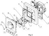
- such an electrical socket outlet mainly consists of a base part 1, one on the base part 1 designable support ring 2, a design frame 3 and a socket center 4.
- the design frame 3 and the socket center 4 represent the overall design cover.
- the provided with the support ring 2 base part 1 establishes the electrical connection to the installation system of the building, with two different lighting devices electrically conductive can be connected to the located in the base part 1 terminal contact parts 10.
- the base part 1 made of plastic consists of a lower base part 1A and a base upper part 1B.
- a receiving space A is provided which is provided for accommodating the essential components of the first illumination device.
- a first electrical circuit board L equipped with a first illuminant M is accommodated in the accommodating space A.
- the first light-emitting means M is designed as an LED and feeds its light into a first light-guiding element S, which is rod-shaped and guided through the upper base part 1B into a first opening O of the socket center piece 4.
- the opening O is closed on the outside by a so-called optical lens LS provided for the extraction of light.
- the light emitted by the first light source M is thus coupled on the one hand into the first light-guiding element S, guided to its end region projecting into the first opening O and emitted to the outside via the lens LS.
- the first printed circuit board L of the first illumination device can be electrically conductively connected to the two terminal contact parts 10.
- the two first contact springs F are in this case with their first end portion E1 directly to the associated terminal contact part 10 in conjunction and come in each case with its second end portion E2 to the associated contact surface of the first circuit board L to the plant.
- the two terminal contact parts 10 are arranged in corresponding formed receiving chambers of the base part 1A.
- the first illumination device fulfills the functional area or the illumination purpose of the control illumination.
- a control light is intended to clearly indicate to the users whether the particular socket is carrying power. Ie. the socket outlet carries electricity, is the functional lighting in operation. It can thus be recognized quickly and clearly whether a consumer to be connected can be operated with security immediately. Often, such information is necessary in hospitals to be able to decide quickly in an emergency to which safety socket to connect a device or consumer.
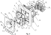
- the second electrical circuit board 6 of the second illumination device is received by a support plate 8.
- the support plate 8 and the second circuit board 6 are arranged below the socket center 4 within the passage opening 9 of the design frame 3.
- the socket central piece 4 is provided with a, the light exit of the second light emitting means 5 enabling second opening 11.
- four, each formed as an LED, second illuminant 5 on the second circuit board 6 are present.
- the socket central piece 4 has a second opening 11, which extends like a slot over an edge region of the socket center piece 4.
- a correspondingly elongated second light-guiding element 12 is arranged, on the one hand, with its coupling-out region in the second opening 11 and, on the other hand, assigned to the four second light-emitting means 5 for light coupling with its light-coupling region.
- the two for producing the electrical connection - as already described above - provided contact spring elements 7 are received by a guide and holding housing 13.
- the second circuit board 6 is equipped with a brightness sensor 14, which is associated with a further opening 15 of the socket center piece 4, wherein the further opening 15 is closed by a further optical lens 16.
- the second illumination device fulfills the functional area or the lighting purpose Ambient Lighting.
- Ambient Lighting is intended to be realized with light for users a visually appealing appearance.
- the brightness sensor 14 arranged on the second printed circuit board 6 ensures that the second lighting means 5 are put into operation at a correspondingly weak ambient brightness be and emit their light over the second light guide 12 as Ambientebeleuchtung to the environment.
- Such Ambientebeleuchtung can z. B. used in the nursery as a night light, in longer hallways as a basic lighting or as a guide lighting. Since the second circuit board 6 is equipped with a plurality of second light sources 5, it is possible, for. B. assign one of the second light source 5 another functional area or lighting purpose. The assignment can then z. B. be exploited to realize a functional lighting.
- a receiving space A is provided, which is provided for accommodating the essential components of the first lighting device.
- a first electrical circuit board L equipped with a first lighting means M is accommodated in the receiving space A.
- the first light-emitting means M is designed as an LED and feeds its light into a first light-guiding element S, which is rod-shaped and guided through the upper base part 1B into a first opening O of the socket center piece 4.
- the opening O is closed on the outside by a so-called optical lens LS provided for the extraction of light.
- the light emitted by the first light source M is thus coupled on the one hand into the first light-guiding element S, guided to its end region projecting into the first opening O and emitted to the outside via the lens LS.
- the first printed circuit board L of the first illumination device can be electrically conductively connected to the two terminal contact parts 10.
- the two first contact springs F are in this case with their first end portion E1 directly to the associated terminal contact part 10 in conjunction and come in each case with its second end portion E2 to the associated contact surface of the first circuit board L to the plant.
- the two terminal contact parts 10 are arranged in corresponding formed receiving chambers of the base part 1A. As well as in particular the FIG.
- the second electrical circuit board 6 of the second illumination device is received by a support plate 8.
- the support plate 8 and the second circuit board 6 are arranged below the socket center 4 within the passage opening 9 of the design frame 3.
- Terminal contact parts 10 made.
- the socket central piece 4 is provided with a, the light exit of the second light emitting means 5 enabling second opening 11. In the present case, four, each formed as an LED, second illuminant 5 on the second circuit board 6 are present.
- the socket central piece 4 has a second opening 11, which extends like a slot over an edge region of the socket center piece 4.
- a correspondingly elongated second light-guiding element 12 is arranged, on the one hand, with its coupling-out region in the second opening 11 and, on the other hand, assigned to the four second light-emitting means 5 for light coupling with its light-coupling region.
- the two for producing the electrical connection - as already described above - provided contact spring elements 7 are received by a guide and holding housing 13.
- the second circuit board 6 is equipped with a brightness sensor 14, which is associated with a further opening 15 of the socket center piece 4, wherein the further opening 15 is closed by a further optical lens 16.
- the first illumination device fulfills the functional area or the illumination purpose of the control illumination.
- a control light is intended to clearly indicate to the users whether the particular socket is carrying power. Ie. If the earthing contact socket carries electricity, the functional lighting is in operation. It can thus be recognized quickly and clearly whether a consumer to be connected can be operated with security immediately. Often, such information is necessary in hospitals to be able to decide quickly in an emergency to which safety socket to connect a device or consumer.
- the second illumination device fulfills the functional area or the lighting purpose Ambient Lighting. Such Ambientebeleuchtung is intended to be realized with light for users a visually appealing appearance.
- the arranged on the second printed circuit board 6 brightness sensor 14 ensures that at a correspondingly weak ambient brightness, the second light source 5 are put into operation and emit their light on the second light guide 12 as ambient lighting to the environment.
- Such Ambientebeleuchtung can z. B. used in the nursery as a night light, in longer hallways as a basic lighting or as a guide lighting.
Landscapes
- Engineering & Computer Science (AREA)
- Architecture (AREA)
- Civil Engineering (AREA)
- Structural Engineering (AREA)
- Arrangement Of Elements, Cooling, Sealing, Or The Like Of Lighting Devices (AREA)
- Details Of Connecting Devices For Male And Female Coupling (AREA)
- Non-Portable Lighting Devices Or Systems Thereof (AREA)
Priority Applications (1)
| Application Number | Priority Date | Filing Date | Title |
|---|---|---|---|
| PL12172347T PL2579398T3 (pl) | 2011-10-07 | 2012-06-18 | Elektryczne gniazdo wtykowe z zestykiem ochronnym |
Applications Claiming Priority (1)
| Application Number | Priority Date | Filing Date | Title |
|---|---|---|---|
| DE102011054266A DE102011054266B3 (de) | 2011-10-07 | 2011-10-07 | Elektrische Schutzkontaktsteckdose |
Publications (2)
| Publication Number | Publication Date |
|---|---|
| EP2579398A1 EP2579398A1 (de) | 2013-04-10 |
| EP2579398B1 true EP2579398B1 (de) | 2018-01-17 |
Family
ID=46456350
Family Applications (1)
| Application Number | Title | Priority Date | Filing Date |
|---|---|---|---|
| EP12172347.2A Active EP2579398B1 (de) | 2011-10-07 | 2012-06-18 | Elektrische Schutzkontaktsteckdose |
Country Status (4)
| Country | Link |
|---|---|
| EP (1) | EP2579398B1 (pl) |
| DE (1) | DE102011054266B3 (pl) |
| ES (1) | ES2666004T3 (pl) |
| PL (1) | PL2579398T3 (pl) |
Cited By (1)
| Publication number | Priority date | Publication date | Assignee | Title |
|---|---|---|---|---|
| DE102022123744A1 (de) * | 2022-09-16 | 2024-03-21 | Albrecht Jung Gmbh & Co. Kg | Elektrisches/elektronisches Gerät |
Families Citing this family (4)
| Publication number | Priority date | Publication date | Assignee | Title |
|---|---|---|---|---|
| DE202013007161U1 (de) * | 2013-08-12 | 2013-10-10 | Abb Ag | Elektrisches Installationsgerät mit Beleuchtungselement |
| DE102016111959B3 (de) * | 2016-06-30 | 2017-11-02 | Albrecht Jung Gmbh & Co. Kg | Elektrische Schutzkontaktsteckdose |
| DE102016111957B4 (de) | 2016-06-30 | 2018-07-19 | Albrecht Jung Gmbh & Co. Kg | Elektrisches/elektronisches Gerät |
| DE102018106105A1 (de) * | 2018-03-15 | 2019-09-19 | Berker Gmbh & Co. Kg | Elektronikmodul für ein elektrisches Installationsgerät |
Family Cites Families (7)
| Publication number | Priority date | Publication date | Assignee | Title |
|---|---|---|---|---|
| US6827602B2 (en) * | 2003-04-30 | 2004-12-07 | Leviton Manufacturing Co., Inc. | Hospital grade receptacle with power light indicator |
| DE10334247B3 (de) * | 2003-07-28 | 2004-11-11 | Berker Gmbh & Co. Kg | Elektrische Schutzkontaktsteckdose |
| DE202006006105U1 (de) * | 2006-04-15 | 2006-08-10 | Gira Giersiepen Gmbh & Co. Kg | Elektro-Installationsgerät sowie zugehörige Zentralabdeckung |
| DE102007018177B3 (de) * | 2007-04-18 | 2008-08-14 | Abb Ag | Steckdose mit Orientierungsbeleuchtung |
| DE102007046818B4 (de) * | 2007-09-29 | 2018-01-25 | Elso Gmbh | Elektrische Steckdose |
| DE102008064454A1 (de) * | 2008-12-22 | 2010-07-01 | Schneider Electric Industries Sas | Elektrisches Installationsgerät |
| DE102009031586B3 (de) * | 2009-07-03 | 2011-01-13 | Berker Gmbh & Co. Kg | Elektrisches Installationsgerät |
-
2011
- 2011-10-07 DE DE102011054266A patent/DE102011054266B3/de not_active Expired - Fee Related
-
2012
- 2012-06-18 PL PL12172347T patent/PL2579398T3/pl unknown
- 2012-06-18 EP EP12172347.2A patent/EP2579398B1/de active Active
- 2012-06-18 ES ES12172347.2T patent/ES2666004T3/es active Active
Non-Patent Citations (1)
| Title |
|---|
| None * |
Cited By (2)
| Publication number | Priority date | Publication date | Assignee | Title |
|---|---|---|---|---|
| DE102022123744A1 (de) * | 2022-09-16 | 2024-03-21 | Albrecht Jung Gmbh & Co. Kg | Elektrisches/elektronisches Gerät |
| DE102022123744B4 (de) * | 2022-09-16 | 2025-05-08 | Albrecht Jung Gmbh & Co. Kg | Elektrisches/elektronisches Gerät |
Also Published As
| Publication number | Publication date |
|---|---|
| PL2579398T3 (pl) | 2018-06-29 |
| EP2579398A1 (de) | 2013-04-10 |
| DE102011054266B3 (de) | 2012-11-29 |
| ES2666004T3 (es) | 2018-04-30 |
Similar Documents
| Publication | Publication Date | Title |
|---|---|---|
| EP1848070B1 (de) | Elektrisches/elektronisches Installationsgerät | |
| EP3114403B1 (de) | Leuchte mit auswechselbaren leuchtmodulen | |
| EP2579398B1 (de) | Elektrische Schutzkontaktsteckdose | |
| EP1983620B1 (de) | Steckdose mit Orientierungsbeleuchtung | |
| DE102007001850B3 (de) | Installationsschalter oder -taster mit Beleuchtung und Baukastensystem zur Bildung eines Installationsschalters oder -tasters mit Beleuchtung | |
| EP1610422B1 (de) | Elektrische Steckvorrichtung | |
| AT14620U1 (de) | Leuchte mit Trägerelement und lösbar befestigbarem Leuchtmodul | |
| EP2429044B1 (de) | Elektrisches Installationsgerät | |
| EP3527886B1 (de) | Anordnung umfassend ein electrisches/elektrisches installationsgerät und eine electrische leuchte | |
| DE102007046818B4 (de) | Elektrische Steckdose | |
| EP2364520B1 (de) | Elektrisches installationsgerät | |
| DE202017103604U1 (de) | Beleuchtungseinrichtung | |
| EP2518848B1 (de) | Rahmen für elektrisches Installationsgerät. | |
| EP2187485B1 (de) | Elektrische Steckdose | |
| EP2202856B1 (de) | Elektrisches Installationsgerät | |
| DE102009031588B4 (de) | Elektrische Steckvorrichtung | |
| EP2184817A1 (de) | Elektrisches Installationsgerät | |
| EP2508796A2 (de) | Beleuchtungseinrichtung | |
| EP3879547B1 (de) | Elektrisches installationsgerät mit integrierter beleuchtung | |
| EP3527887A1 (de) | Elektrische leuchte | |
| DE102016111959B3 (de) | Elektrische Schutzkontaktsteckdose | |
| DE10334247B3 (de) | Elektrische Schutzkontaktsteckdose | |
| EP1988615B1 (de) | Unterputz-Steckdose mit Leuchtmittelmodul | |
| DE102018103375B3 (de) | Elektrische Leuchte | |
| DE102017109135B3 (de) | Beleuchtungseinrichtung für eine Unterputzinstallationsdose mit einer verschwenkbaren und/oder verdrehbaren kugelförmigen Leuchte, die durch zwei Clipselemente befestigt ist |
Legal Events
| Date | Code | Title | Description |
|---|---|---|---|
| PUAI | Public reference made under article 153(3) epc to a published international application that has entered the european phase |
Free format text: ORIGINAL CODE: 0009012 |
|
| AK | Designated contracting states |
Kind code of ref document: A1 Designated state(s): AL AT BE BG CH CY CZ DE DK EE ES FI FR GB GR HR HU IE IS IT LI LT LU LV MC MK MT NL NO PL PT RO RS SE SI SK SM TR |
|
| AX | Request for extension of the european patent |
Extension state: BA ME |
|
| 17P | Request for examination filed |
Effective date: 20130429 |
|
| 17Q | First examination report despatched |
Effective date: 20160506 |
|
| GRAP | Despatch of communication of intention to grant a patent |
Free format text: ORIGINAL CODE: EPIDOSNIGR1 |
|
| INTG | Intention to grant announced |
Effective date: 20170810 |
|
| GRAS | Grant fee paid |
Free format text: ORIGINAL CODE: EPIDOSNIGR3 |
|
| GRAA | (expected) grant |
Free format text: ORIGINAL CODE: 0009210 |
|
| RIN1 | Information on inventor provided before grant (corrected) |
Inventor name: LUDWIG, RALF Inventor name: KUTZEHR, TOBIAS |
|
| AK | Designated contracting states |
Kind code of ref document: B1 Designated state(s): AL AT BE BG CH CY CZ DE DK EE ES FI FR GB GR HR HU IE IS IT LI LT LU LV MC MK MT NL NO PL PT RO RS SE SI SK SM TR |
|
| REG | Reference to a national code |
Ref country code: GB Ref legal event code: FG4D Free format text: NOT ENGLISH |
|
| REG | Reference to a national code |
Ref country code: CH Ref legal event code: EP |
|
| REG | Reference to a national code |
Ref country code: IE Ref legal event code: FG4D Free format text: LANGUAGE OF EP DOCUMENT: GERMAN |
|
| REG | Reference to a national code |
Ref country code: AT Ref legal event code: REF Ref document number: 965026 Country of ref document: AT Kind code of ref document: T Effective date: 20180215 |
|
| REG | Reference to a national code |
Ref country code: DE Ref legal event code: R096 Ref document number: 502012012016 Country of ref document: DE |
|
| REG | Reference to a national code |
Ref country code: ES Ref legal event code: FG2A Ref document number: 2666004 Country of ref document: ES Kind code of ref document: T3 Effective date: 20180430 |
|
| REG | Reference to a national code |
Ref country code: NL Ref legal event code: MP Effective date: 20180117 |
|
| REG | Reference to a national code |
Ref country code: LT Ref legal event code: MG4D |
|
| REG | Reference to a national code |
Ref country code: FR Ref legal event code: PLFP Year of fee payment: 7 |
|
| PG25 | Lapsed in a contracting state [announced via postgrant information from national office to epo] |
Ref country code: NL Free format text: LAPSE BECAUSE OF FAILURE TO SUBMIT A TRANSLATION OF THE DESCRIPTION OR TO PAY THE FEE WITHIN THE PRESCRIBED TIME-LIMIT Effective date: 20180117 |
|
| PG25 | Lapsed in a contracting state [announced via postgrant information from national office to epo] |
Ref country code: NO Free format text: LAPSE BECAUSE OF FAILURE TO SUBMIT A TRANSLATION OF THE DESCRIPTION OR TO PAY THE FEE WITHIN THE PRESCRIBED TIME-LIMIT Effective date: 20180417 Ref country code: CY Free format text: LAPSE BECAUSE OF FAILURE TO SUBMIT A TRANSLATION OF THE DESCRIPTION OR TO PAY THE FEE WITHIN THE PRESCRIBED TIME-LIMIT Effective date: 20180117 Ref country code: HR Free format text: LAPSE BECAUSE OF FAILURE TO SUBMIT A TRANSLATION OF THE DESCRIPTION OR TO PAY THE FEE WITHIN THE PRESCRIBED TIME-LIMIT Effective date: 20180117 Ref country code: FI Free format text: LAPSE BECAUSE OF FAILURE TO SUBMIT A TRANSLATION OF THE DESCRIPTION OR TO PAY THE FEE WITHIN THE PRESCRIBED TIME-LIMIT Effective date: 20180117 Ref country code: LT Free format text: LAPSE BECAUSE OF FAILURE TO SUBMIT A TRANSLATION OF THE DESCRIPTION OR TO PAY THE FEE WITHIN THE PRESCRIBED TIME-LIMIT Effective date: 20180117 |
|
| PG25 | Lapsed in a contracting state [announced via postgrant information from national office to epo] |
Ref country code: RS Free format text: LAPSE BECAUSE OF FAILURE TO SUBMIT A TRANSLATION OF THE DESCRIPTION OR TO PAY THE FEE WITHIN THE PRESCRIBED TIME-LIMIT Effective date: 20180117 Ref country code: GR Free format text: LAPSE BECAUSE OF FAILURE TO SUBMIT A TRANSLATION OF THE DESCRIPTION OR TO PAY THE FEE WITHIN THE PRESCRIBED TIME-LIMIT Effective date: 20180418 Ref country code: BG Free format text: LAPSE BECAUSE OF FAILURE TO SUBMIT A TRANSLATION OF THE DESCRIPTION OR TO PAY THE FEE WITHIN THE PRESCRIBED TIME-LIMIT Effective date: 20180417 Ref country code: LV Free format text: LAPSE BECAUSE OF FAILURE TO SUBMIT A TRANSLATION OF THE DESCRIPTION OR TO PAY THE FEE WITHIN THE PRESCRIBED TIME-LIMIT Effective date: 20180117 Ref country code: IS Free format text: LAPSE BECAUSE OF FAILURE TO SUBMIT A TRANSLATION OF THE DESCRIPTION OR TO PAY THE FEE WITHIN THE PRESCRIBED TIME-LIMIT Effective date: 20180517 Ref country code: SE Free format text: LAPSE BECAUSE OF FAILURE TO SUBMIT A TRANSLATION OF THE DESCRIPTION OR TO PAY THE FEE WITHIN THE PRESCRIBED TIME-LIMIT Effective date: 20180117 |
|
| PG25 | Lapsed in a contracting state [announced via postgrant information from national office to epo] |
Ref country code: MT Free format text: LAPSE BECAUSE OF FAILURE TO SUBMIT A TRANSLATION OF THE DESCRIPTION OR TO PAY THE FEE WITHIN THE PRESCRIBED TIME-LIMIT Effective date: 20180117 |
|
| REG | Reference to a national code |
Ref country code: DE Ref legal event code: R097 Ref document number: 502012012016 Country of ref document: DE |
|
| PG25 | Lapsed in a contracting state [announced via postgrant information from national office to epo] |
Ref country code: AL Free format text: LAPSE BECAUSE OF FAILURE TO SUBMIT A TRANSLATION OF THE DESCRIPTION OR TO PAY THE FEE WITHIN THE PRESCRIBED TIME-LIMIT Effective date: 20180117 Ref country code: EE Free format text: LAPSE BECAUSE OF FAILURE TO SUBMIT A TRANSLATION OF THE DESCRIPTION OR TO PAY THE FEE WITHIN THE PRESCRIBED TIME-LIMIT Effective date: 20180117 Ref country code: RO Free format text: LAPSE BECAUSE OF FAILURE TO SUBMIT A TRANSLATION OF THE DESCRIPTION OR TO PAY THE FEE WITHIN THE PRESCRIBED TIME-LIMIT Effective date: 20180117 |
|
| PLBE | No opposition filed within time limit |
Free format text: ORIGINAL CODE: 0009261 |
|
| STAA | Information on the status of an ep patent application or granted ep patent |
Free format text: STATUS: NO OPPOSITION FILED WITHIN TIME LIMIT |
|
| PG25 | Lapsed in a contracting state [announced via postgrant information from national office to epo] |
Ref country code: SK Free format text: LAPSE BECAUSE OF FAILURE TO SUBMIT A TRANSLATION OF THE DESCRIPTION OR TO PAY THE FEE WITHIN THE PRESCRIBED TIME-LIMIT Effective date: 20180117 Ref country code: CZ Free format text: LAPSE BECAUSE OF FAILURE TO SUBMIT A TRANSLATION OF THE DESCRIPTION OR TO PAY THE FEE WITHIN THE PRESCRIBED TIME-LIMIT Effective date: 20180117 Ref country code: DK Free format text: LAPSE BECAUSE OF FAILURE TO SUBMIT A TRANSLATION OF THE DESCRIPTION OR TO PAY THE FEE WITHIN THE PRESCRIBED TIME-LIMIT Effective date: 20180117 Ref country code: SM Free format text: LAPSE BECAUSE OF FAILURE TO SUBMIT A TRANSLATION OF THE DESCRIPTION OR TO PAY THE FEE WITHIN THE PRESCRIBED TIME-LIMIT Effective date: 20180117 |
|
| 26N | No opposition filed |
Effective date: 20181018 |
|
| REG | Reference to a national code |
Ref country code: CH Ref legal event code: PL |
|
| PG25 | Lapsed in a contracting state [announced via postgrant information from national office to epo] |
Ref country code: SI Free format text: LAPSE BECAUSE OF FAILURE TO SUBMIT A TRANSLATION OF THE DESCRIPTION OR TO PAY THE FEE WITHIN THE PRESCRIBED TIME-LIMIT Effective date: 20180117 |
|
| REG | Reference to a national code |
Ref country code: IE Ref legal event code: MM4A |
|
| PG25 | Lapsed in a contracting state [announced via postgrant information from national office to epo] |
Ref country code: LU Free format text: LAPSE BECAUSE OF NON-PAYMENT OF DUE FEES Effective date: 20180618 Ref country code: MC Free format text: LAPSE BECAUSE OF FAILURE TO SUBMIT A TRANSLATION OF THE DESCRIPTION OR TO PAY THE FEE WITHIN THE PRESCRIBED TIME-LIMIT Effective date: 20180117 |
|
| PG25 | Lapsed in a contracting state [announced via postgrant information from national office to epo] |
Ref country code: CH Free format text: LAPSE BECAUSE OF NON-PAYMENT OF DUE FEES Effective date: 20180630 Ref country code: LI Free format text: LAPSE BECAUSE OF NON-PAYMENT OF DUE FEES Effective date: 20180630 Ref country code: IE Free format text: LAPSE BECAUSE OF NON-PAYMENT OF DUE FEES Effective date: 20180618 |
|
| PG25 | Lapsed in a contracting state [announced via postgrant information from national office to epo] |
Ref country code: TR Free format text: LAPSE BECAUSE OF FAILURE TO SUBMIT A TRANSLATION OF THE DESCRIPTION OR TO PAY THE FEE WITHIN THE PRESCRIBED TIME-LIMIT Effective date: 20180117 |
|
| PG25 | Lapsed in a contracting state [announced via postgrant information from national office to epo] |
Ref country code: HU Free format text: LAPSE BECAUSE OF FAILURE TO SUBMIT A TRANSLATION OF THE DESCRIPTION OR TO PAY THE FEE WITHIN THE PRESCRIBED TIME-LIMIT; INVALID AB INITIO Effective date: 20120618 Ref country code: PT Free format text: LAPSE BECAUSE OF FAILURE TO SUBMIT A TRANSLATION OF THE DESCRIPTION OR TO PAY THE FEE WITHIN THE PRESCRIBED TIME-LIMIT Effective date: 20180117 |
|
| PG25 | Lapsed in a contracting state [announced via postgrant information from national office to epo] |
Ref country code: MK Free format text: LAPSE BECAUSE OF NON-PAYMENT OF DUE FEES Effective date: 20180117 |
|
| P01 | Opt-out of the competence of the unified patent court (upc) registered |
Effective date: 20230606 |
|
| PGFP | Annual fee paid to national office [announced via postgrant information from national office to epo] |
Ref country code: PL Payment date: 20250603 Year of fee payment: 14 Ref country code: DE Payment date: 20250627 Year of fee payment: 14 |
|
| PGFP | Annual fee paid to national office [announced via postgrant information from national office to epo] |
Ref country code: GB Payment date: 20250627 Year of fee payment: 14 |
|
| PGFP | Annual fee paid to national office [announced via postgrant information from national office to epo] |
Ref country code: BE Payment date: 20250627 Year of fee payment: 14 |
|
| PGFP | Annual fee paid to national office [announced via postgrant information from national office to epo] |
Ref country code: FR Payment date: 20250625 Year of fee payment: 14 |
|
| PGFP | Annual fee paid to national office [announced via postgrant information from national office to epo] |
Ref country code: AT Payment date: 20250603 Year of fee payment: 14 |
|
| PGFP | Annual fee paid to national office [announced via postgrant information from national office to epo] |
Ref country code: ES Payment date: 20250701 Year of fee payment: 14 |
|
| PGFP | Annual fee paid to national office [announced via postgrant information from national office to epo] |
Ref country code: IT Payment date: 20250619 Year of fee payment: 14 |