EP2579254B1 - Signalverarbeitungsverfahren, informationsverarbeitungsvorrichtung und signalverarbeitungsprogramm - Google Patents
Signalverarbeitungsverfahren, informationsverarbeitungsvorrichtung und signalverarbeitungsprogramm Download PDFInfo
- Publication number
- EP2579254B1 EP2579254B1 EP11786559.2A EP11786559A EP2579254B1 EP 2579254 B1 EP2579254 B1 EP 2579254B1 EP 11786559 A EP11786559 A EP 11786559A EP 2579254 B1 EP2579254 B1 EP 2579254B1
- Authority
- EP
- European Patent Office
- Prior art keywords
- noise
- noise information
- audio signal
- information
- unit
- Prior art date
- Legal status (The legal status is an assumption and is not a legal conclusion. Google has not performed a legal analysis and makes no representation as to the accuracy of the status listed.)
- Active
Links
- 238000003672 processing method Methods 0.000 title claims description 18
- 230000010365 information processing Effects 0.000 title claims description 7
- 230000001629 suppression Effects 0.000 claims description 88
- 238000001228 spectrum Methods 0.000 claims description 78
- 238000000034 method Methods 0.000 claims description 58
- 230000005236 sound signal Effects 0.000 claims description 35
- 238000004458 analytical method Methods 0.000 claims description 31
- 238000001514 detection method Methods 0.000 claims description 9
- 230000008569 process Effects 0.000 claims description 2
- 230000004048 modification Effects 0.000 description 56
- 238000012986 modification Methods 0.000 description 56
- 230000009466 transformation Effects 0.000 description 41
- 238000010586 diagram Methods 0.000 description 27
- 238000011156 evaluation Methods 0.000 description 11
- 238000009408 flooring Methods 0.000 description 10
- 230000006870 function Effects 0.000 description 10
- 238000004364 calculation method Methods 0.000 description 9
- 230000008859 change Effects 0.000 description 8
- 238000012545 processing Methods 0.000 description 8
- 230000000694 effects Effects 0.000 description 5
- 238000005516 engineering process Methods 0.000 description 5
- 230000009467 reduction Effects 0.000 description 5
- 230000015572 biosynthetic process Effects 0.000 description 4
- 239000000203 mixture Substances 0.000 description 4
- 230000003595 spectral effect Effects 0.000 description 4
- 238000003786 synthesis reaction Methods 0.000 description 4
- 238000013459 approach Methods 0.000 description 2
- 230000002708 enhancing effect Effects 0.000 description 2
- 230000010354 integration Effects 0.000 description 2
- 238000012935 Averaging Methods 0.000 description 1
- 230000005534 acoustic noise Effects 0.000 description 1
- 230000006978 adaptation Effects 0.000 description 1
- 230000008901 benefit Effects 0.000 description 1
- 238000004891 communication Methods 0.000 description 1
- 230000014509 gene expression Effects 0.000 description 1
- 230000006872 improvement Effects 0.000 description 1
- 239000004065 semiconductor Substances 0.000 description 1
Images


Classifications
-
- G—PHYSICS
- G10—MUSICAL INSTRUMENTS; ACOUSTICS
- G10L—SPEECH ANALYSIS TECHNIQUES OR SPEECH SYNTHESIS; SPEECH RECOGNITION; SPEECH OR VOICE PROCESSING TECHNIQUES; SPEECH OR AUDIO CODING OR DECODING
- G10L21/00—Speech or voice signal processing techniques to produce another audible or non-audible signal, e.g. visual or tactile, in order to modify its quality or its intelligibility
- G10L21/02—Speech enhancement, e.g. noise reduction or echo cancellation
- G10L21/0208—Noise filtering
Definitions
- the present invention relates to a signal processing technique of suppressing noise in a noisy signal to enhance a target signal.
- a noise suppressing technology is known as a signal processing technology of suppressing noise in a noisy signal (a signal containing a mixture of a target signal and noise) partially or entirely and outputting an enhanced signal (a signal obtained by enhancing a target signal).
- a noise suppressor is a system that suppresses noise superposed on a target audio signal.
- the noise suppressor is used in various audio terminals such as mobile phones.
- patent literature 1 discloses a method of suppressing noise by multiplying an input signal by a suppression coefficient smaller than 1.
- Patent literature 2 discloses a method of suppressing noise by directly subtracting estimated noise from a noisy signal.
- patent literature 1 and 2 need to estimate noise from the target signal that has already become noisy due to the mixed noise.
- the methods disclosed in patent literature 1 and 2 are effective only when noise is much smaller than a target signal. If the condition that the noise is sufficiently smaller than the target signal is not satisfied, accuracy of a noise estimation value is poor. For this reason, the methods disclosed in patent literature 1 and 2 can achieve no sufficient noise suppression effect, and the enhanced signal includes a large distortion.
- patent literature 3 discloses a noise suppression system that can realize enough noise suppression effect and small distortion in the enhanced signal even if the condition that the noise is sufficiently smaller than the target signal is not satisfied. Assuming that the characteristics of noise to be mixed into the target signal are known to some extent in advance, the method disclosed in patent literature 3 suppresses the noise by subtracting noise information (information about the noise characteristics) which is recorded in advance from the noisy signal. Patent literature 3 also discloses a method of multiplying the noise information by a large coefficient if input signal power obtained by analyzing an input signal is large; or a small coefficient if the input signal power is small, and subtracting the multiplication result from the noisy signal.
- the object of the present invention is to provide a signal processing technology which settles the above-mentioned problems.
- an audio signal processing method includes: analyzing a noisy audio signal that is supplied as an input signal; generating mixed noise information by mixing a plurality of noise information about one kind of known noise to be suppressed and stored in a memory in advance with a method which is determined based on the result of said analysis of the noisy audio signal; and suppressing said one kind of known noise using said mixed noise information.
- an audio information processing apparatus according to claim 16 is provided.
- a program recording medium according to claim 17 is provided.
- the present invention provides a signal processing technology which can realize noise suppression for highly nonstationary signals with many changes in their characteristics.
- a noise suppressing apparatus 100 will be described as the first exemplary embodiment that realizes a signal processing method according to the present invention.
- the noise suppressing apparatus 100 suppresses noise in a noisy signal (a signal containing a mixture of a target signal and noise) partially or entirely, and outputs an enhanced signal (a signal obtained by enhancing the target signal).
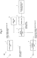
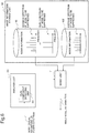
- Fig. 1 is a block diagram showing the entire structure of the noise suppressing apparatus 100.
- the noise suppressing apparatus 100 also functions as a part of equipment such as digital cameras, laptop computers and mobile phones, for example.
- the present invention is not limited to this, and it can be applied to all information processing devices that need removal of noise from an input signal.
- the noise suppressing apparatus 100 includes an input terminal 1, a transformation unit 2, a noise suppression unit 3, an inverse transformation unit 4, an output terminal 5, an analysis unit 10, a mixing unit 11 and a noise information storage unit 6.
- this noise suppressing apparatus 100 analyzes a noisy signal that is supplied as an input signal, generates mixed noise information (pseudo noise information) by a mixing method according to the analysis result using noise information stored in advance, and suppresses the noise using the mixed noise information.
- At least one of a plurality of noise information to be mixed is stored in the noise information storage unit 6 in advance.
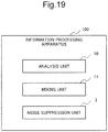
- FIG. 19 Another example of a block diagram of an information processing apparatus (noise suppressing apparatus) 100 is shown in Fig. 19 .
- the information processing apparatus 100 includes the analysis unit 10, the mixing unit 11 and the noise suppression unit 3. Description will be made using Fig. 1 below.
- a noisy signal is supplied to the input terminal 1 as a series of sample values.
- the noisy signal supplied to the input terminal 1 undergoes transformation such as Fourier transformation in the transformation unit 2 and is decomposed into a plurality of frequency components.
- a magnitude spectrum of a plurality of frequency components is supplied to the noise suppression unit 3, and a phase spectrum is transmitted to the inverse transformation unit 4.
- a magnitude spectrum is supplied here.
- the present invention is not limited to this, and a power spectrum corresponding to the square of the magnitude spectrum may be supplied to the noise suppression unit 3.
- the noise information storage unit 6 includes a memory device such as a semiconductor memory, and stores information on characteristics of known noise as a suppression target (noise information).
- the known noise stored as a suppression target is such as a shutter sound, a motor-driving sound, a zooming sound and focusing noise of an automatic focusing system (a clicking sound) or the like.
- the analysis unit 10 takes in a noisy signal magnitude spectrum generated by the transformation unit 2 and analyzes it. By analyzing the noisy signal magnitude spectrum, the analysis unit 10 determines the characteristics of the noise included in the noisy signal, and determines a mixing method of noise information conforming to the characteristics. Then, the analysis unit 10 hands the determined mixing method to the mixing unit 11.
- the mixing unit 11 According to the mixing method received from the analysis unit 10, the mixing unit 11 generates mixed noise information from the noise information stored in the noise information storage unit 6.
- the noise suppression unit 3 suppresses noise in each frequency and transmits an enhanced signal magnitude spectrum as the noise suppression result to the inverse transformation unit 4.
- the inverse transformation unit 4 puts the enhanced signal magnitude spectrum supplied from the noise suppression unit 3 and the phase spectrum of the noisy signal supplied from the transformation unit 2 together to perform the inverse transform, and supplies the result to the output terminal 5 as enhanced signal samples.
- Fig. 2 is a block diagram showing a structure of a transformation unit. As shown in Fig. 2 , the transformation unit includes a frame dividing unit 21, a windowing unit 22 and a Fourier transformation unit 23.
- noisy signal samples are supplied to the frame dividing unit 21 and are divided into a frame for each K/2 samples.
- K is an even number.
- noisy signal samples divided into frames are supplied to the windowing unit 22, and are multiplied by w (t) which is a window function.
- a symmetrical window function is used for a real numbered signal.
- Equation (3) a Hanning window indicated by the following Equation (3) can be used, for example.
- w t ⁇ 0.5 + 0.5 cos ⁇ t ⁇ K / 2 K / 2 , 0 ⁇ t ⁇ K 0 , otherwise
- window functions such as Hamming window, Kaiser window and Blackman window are also known.
- the output of windowing is supplied to the Fourier transformation unit 23 and is transformed into a noisy signal spectrum Yn (k).
- the noisy signal spectrum Yn (k) is separated into a phase and a magnitude, and a noisy signal phase spectrum arg Yn (k) is supplied to the inverse transformation unit 4 and a noisy signal magnitude spectrum
- a power spectrum may be used in place of a magnitude spectrum.
- Fig. 3 is a block diagram showing a structure of the inverse transformation unit 4.
- the inverse transformation unit 4 includes an inverse Fourier transformation unit 43, a windowing unit 42 and a frame synthesis unit 41.
- the inverse Fourier transformation unit 43 multiplies an enhanced signal magnitude spectrum supplied from the noise suppression unit 3 by the noisy signal phase spectrum arg Yn (k) supplied from the transformation unit 2, and obtains an enhanced signal (the left-side of the following Equation (4)).
- X n ⁇ k X n ⁇ k ⁇ arg Y n k
- the inverse Fourier transformation unit 43 performs inverse Fourier transform of the obtained enhanced signal.
- x ⁇ n t w t x n t
- the obtained output signal is transmitted from the frame synthesis unit 41 to the output terminal 5.
- the transformation in the transformation unit 2 and the inverse transformation unit 4 has been described as Fourier transform in Fig. 2 and Fig. 3
- the transformation unit 2 and the inverse transformation unit 4 can use another transformation such as cosine transform, modified cosine transform, Hadamard transform, Haar transform or wavelet transform in place of Fourier transform.
- cosine transform and modified cosine transform obtain only the magnitude as a transformation result
- a route to the inverse transformation unit 4 from the transformation unit 2 in Fig. 1 becomes unnecessary.
- noise information to be recorded in the noise information storage unit 6 is only for the magnitude (or power), it contributes to a reduction in storage capacity and a reduction in amount of calculation in the noise suppression processing.
- Haar transform does not need multiplications, and thus the area when the function is integrated into an LSI can be reduced.
- wavelet transform improvement of a noise suppression effect can be expected because different time resolutions can be applied according to the frequency.
- the noise suppression unit 3 can perform actual suppression after the transformation unit 2 has integrated a plurality of frequency components. On this occasion, by integrating more frequency components in low frequency ranges where auditory discrimination capability is higher than in high frequency ranges, the transformation unit 2 can achieve high sound quality. In addition, when noise suppression is carried out after a plurality of frequency components have been integrated, the noise suppressing apparatus 100 can reduce the total amount of calculation because the number of frequency components in which noise suppression is applied becomes small.
- noise suppression unit 3 can perform various suppressions, there are SS (Spectral Subtraction) method and MMSE STSA (Minimum Mean-Square Error Short-Time Spectral Amplitude Estimator) method as typical ones.
- SS method subtracts mixed noise information supplied by the mixing unit 11 from a noisy signal magnitude spectrum supplied by the transformation unit 2.
- MMSE STSA method calculates a suppression coefficient for each of a plurality of frequency components using mixed noise information supplied from the mixing unit 11 and a noisy signal magnitude spectrum supplied from the transformation unit 2, and multiplies the noisy signal magnitude spectrum by this suppression coefficient. This suppression coefficient is determined so that the mean square power of an enhanced signal should be minimized.
- flooring may be applied in order to avoid excessive suppression.
- Flooring is a method to avoid suppression beyond a maximum suppression quantity. It is a flooring parameter that determines a maximum suppression quantity.
- SS method imposes restriction so that a result of subtraction of modified noise information from a noisy signal magnitude spectrum shall not become smaller than the flooring parameter. Specifically, when a subtraction result is smaller than the flooring parameter value, SS method substitutes the subtraction result with the flooring parameter value. Similarly, when the suppression coefficient obtained from the modified noise information and the noisy signal magnitude spectrum is smaller than the flooring parameter, MMSE STSA method substitutes the suppression coefficient with the flooring parameter. Details of the flooring are disclosed in a document " M. Berouti, R. Schwartz and J.
- the noise suppression unit 3 can also set the number of frequency components of the noise information such that it is smaller than the number of frequency components of the noisy signal spectrum.
- each of a plurality of noise information will be shared by a plurality of frequency components.
- frequency resolution of the noisy signal spectrum is high. Therefore, the noise suppression unit 3 can achieve high sound quality with an amount of calculation less than a case when there is no integration of the frequency components at all. Details of suppression using noise information of the number of frequency components less than the number of frequency components of a noisy signal spectrum are disclosed in Japanese Patent Application Laid-Open No. 2008-203879 .
- Fig. 4 is a diagram for illustrating an internal configuration of the noise information storage unit 6.
- a plurality of noise information 601-60n are stored in the noise information storage unit 6 in advance.
- Noise information 601-60n may be a combination of the maximum and the average noise information of known noise, a combination of the maximum, the average and the minimum noise information, a combination of peak component of noise information and others, or a combination of the impact component of noise information and others, for example.
- Noise information 601-60n may include statistical values such as the variance and the median.
- the noise information storage unit 6 may memorize feature quantities such as the phase frequency characteristics, and strength and variance in time in specific frequencies.
- Average noise information Information obtained by averaging magnitude (or power) of the same frequency component of a plurality of spectra derived by Fourier transform for the whole of known noise (over a plurality of frames). That is, so-called an average spectrum averaged along the time axis.
- Maximum noise information The maximum value of magnitude (or power) of a plurality of the same frequency component of spectra derived by Fourier transform for the whole of known noise (over a plurality of frames) for each frequency component. That is, so-called a maximum spectrum.
- Minimum noise information The minimum value of magnitude (or power) of a plurality of the same frequency component of spectra derived by Fourier transform for the whole of known noise (over a plurality of frames) for each frequency component. That is, so-called the minimum spectrum.
- Peak components of noise information A frequency component in spectra derived by Fourier transform for the whole of known noise (over a plurality of frames) having a significantly large value in the neighborhood when magnitudes are compared along the frequency.
- Impact component of noise information The average of a plurality of spectra derived by Fourier transform in all impact noise frames. That is, so-called an average spectrum of impact noise. Impact noise itself has a large value for a very short duration when changes of an audio signal before Fourier transform in time is observed. In contrast, a spectrum after Fourier transform has a feature that magnitude along frequency is almost constant over a predetermined bandwidth.
- noise suppression for highly nonstationary signals with many changes in their characteristics can be realized.
- average and maximum noise information are to be mixed, it is possible to synthesize an arbitrary value between the average and the maximum by changing a mixing ratio, and thus pseudo noise becomes more accurate, and sound quality by the suppression improves.
- the average and the minimum noise information or the maximum, the average, and the minimum noise information are to be mixed, a similar effect is obtained.
- a noise suppressing apparatus as the second exemplary embodiment of the present invention will be described using Fig. 5 .
- a noise suppressing apparatus according to this exemplary embodiment is different in the contents of a noise information storage unit 61 and the structure of a mixing unit 111, and other structures are the same as those of the first exemplary embodiment. Therefore, a same number is attached to a same structure here, and description will be omitted.
- the noise information storage unit 61 stores only average noise information 611.
- a maximum noise information generation unit 1112 in the mixing unit 111 generates maximum noise information from the average noise information 611.
- a mixing control unit 1111 mixes the average noise information and the generated maximum noise information in a weighted mixing manner.
- the maximum noise information generation unit 1112 generates maximum noise information in this exemplary embodiment, the present invention is not limited to this, and the minimum noise information may be generated from average noise information in the mixing unit 111. Moreover, noise information stored in the noise information storage unit 61 is not limited either to the average noise information 611, and it may be maximum noise information or minimum noise information.
- noise suppression for highly nonstationary signals with many changes in their characteristics can be realized while the storage capacity of the noise information storage unit 61 is kept small.
- a noise suppressing apparatus as the third exemplary embodiment of the present invention will be described using Fig. 6 .
- a noise suppressing apparatus according to this exemplary embodiment is different in the internal configuration of the analysis unit and the contents of the noise information storage unit, and other structures are the same as those of the first exemplary embodiment. Therefore, a same number is attached to a same structure here, and description will be omitted.
- the basic component and a special component of information of noise to be suppressed are stored separately in advance, and if the special component is detected in a noisy signal, mixed noise information is generated using the stored special component.
- storing and detection of a peak component as an example of a special component is performed.
- an analysis unit 101 includes a peak component detecting unit 1011.
- the peak component detecting unit 1011 detects frequency components identified as a peak from a supplied noisy signal spectrum. For example, a frequency component having a magnitude value larger than a predetermined threshold and, in addition, larger than that of the surrounding frequency components is determined as a peak. It is also possible that, when a difference with a magnitude value in the adjacent frequency on both sides is no smaller than a predetermined threshold value, the peak component detecting unit 1011 declares it as a peak component, for example. In a case where a frequency component in which a peak of noise may exist is known in advance, the peak component detecting unit 1011 may search for peaks only in its neighborhood.
- the mixing unit 11 mixes noise information of the frequency component determined to be a peak and others with different ratios.
- the maximum spectrum and the average spectrum of noise to be suppressed are stored in a noise information storage unit 62 as noise information 621 and noise information 622, respectively, in advance.
- peak positions are detected by peak component detection, and the mixing unit 11 should simply change the mixing ratios of the maximum value from the noise information 621 and the mean value from the noise information 622 according to the location (or equivalently the frequency component).
- the peak component detecting unit 1011 may perform peak detection for each of all frequency components (a total of 1024, for example) independently, and, for frequency components having a peak, the mixing unit 11 may mix 80% of the magnitude of the maximum spectrum and 20% of the magnitude of the average spectrum.
- the mixing unit 11 may use 100% of the magnitude of the average spectrum. According to the accuracy of a peak detection (likelihood of peak existence), the mixing unit 11 may change the mixing ratio. For example, the mixing unit 11 may set the magnitude of the maximum spectrum to 100% for a frequency component with a 100% peak-detection confidence.
- a peak component of noise to be suppressed and other components are stored in the noise information storage unit 62 separately in advance, and, as a frequency component determined as a peak, the mixing unit 11 reads the stored peak component, and, as a frequency component determined as a non-peak, it reads the other component. For example, even if a frequency component detected by the peak component detecting unit 1011 deviates from the peak component stored as the noise information 621, when the amount of deviation (the number of steps of frequency) is no more than a predetermined value, the mixing unit 11 performs mixing using the magnitude stored as the peak component.
- the internal configuration of the peak component detecting unit 1011 will be described using Fig. 7 .
- the peak component detecting unit 1011 includes a comparing unit 10111, a delay unit 10112 and a threshold value selection unit 10113 as shown in Fig. 7 .
- a peak tends to exist in the neighborhood (e.g. Frequency components 4-6 and 19-21) of frequencies (e.g. Frequencies 5 and 20) where a peak had been located in the past (such as in the previous frame).
- the peak component detecting unit 1011 detects a peak on the basis of this fact. By making the threshold value of peak detection small only in the neighborhood of such past-peak frequencies, for example, the peak component detecting unit 1011 makes it easy to detect a peak.
- the comparing unit 10111 compares magnitude (or power) in a noisy signal with a threshold value for each frequency component. Then, the comparing unit 10111 stores the information on a frequency component that has been identified as a peak into the delay unit 10112. In the following several frames, the threshold value selection unit 10113 selects a small threshold value in the neighborhood of the frequency where a peak has been detected, and hands it to the comparing unit 10111. As a result, in the neighborhood of the frequency component where a peak has been found once, it becomes easy to detect a peak again.
- the threshold value selection unit 10113 may refer to a frequency of a peak component stored in the noise information storage unit, and, for frequencies in the neighborhood of that frequency, lower the threshold value to make it easy to detect a peak.
- peak components are treated as an independent mixing component. Because peaks exist locally, only the position and the value of a peak can be stored. In other words, according to this exemplary embodiment, because a memory does not need to cover all possible frequency positions, the memory capacity can be reduced. Also, by separating a peak, a dynamic range can be made smaller than a case where the peak and other components are stored in a mixed manner. This leads to improved accuracy, and reduction in the number of bits which further leads to reduction of the memory area. Equivalently, it is useful for cost reduction.
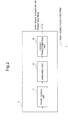
- a noise suppressing apparatus as the fourth exemplary embodiment of the present invention will be described using Fig. 8 .
- This exemplary embodiment will describe a specific example of an internal configuration of a mixing unit shown in Fig. 4 . Because structures besides the mixing unit are the same as those of the first exemplary embodiment, description will be omitted here.
- a mixing unit 112 is equipped with a mixing ratio calculation unit 1131 that calculates mixing ratios of noise information ⁇ 1- ⁇ n based on a result of analysis by the analysis unit 10.
- the calculated mixing ratios ⁇ 1- ⁇ n are handed to multipliers 1121-112n, respectively, and the each of noise information 601-60n are multiplied by the ratios in the respective multipliers 1121-112n.
- the mixing ratio calculation unit 1131 outputs 0.8 as ⁇ 1.
- the multiplier 1121 multiplies the noise information 601 by 0.8.
- the noise information which has been multiplied by the coefficient is supplied to an adder 1132 and added. As a result, mixed noise information is generated.
- noise information is multiplied by a coefficient and undergoes linear addition in this exemplary embodiment as an example, the present invention is not limited to this, and noise information may be mixed nonlinearly using a mathematical equation according to a result of analysis, for example.
- a noise suppressing apparatus as the fifth exemplary embodiment of the present invention will be described using Fig. 9 .
- this exemplary embodiment another example of an internal configuration of the mixing unit 11 indicated in the first exemplary embodiment will be described. Because structures besides the detecting unit are the same as those of the first exemplary embodiment, the same numbers are attached to the same structures here, and description will be omitted.
- an analysis unit 102 has a similarity degree evaluation unit 1021.
- a noise to be suppressed in this exemplary embodiment is special noise information having a special spectrum shape.
- the similarity degree evaluation unit 1021 evaluates the similarity between a special noise information 632 stored in a noise information storage unit 63 in advance and an inputted noisy signal spectrum. Then, the special noise information 632 is mixed with a weight corresponding to its similarity degree.
- the similarity degree evaluation unit 1021 stores an impact noise spectrum (having almost constant magnitude over a predetermined frequency range) as the special noise information 632, and evaluates the similarity degree between the shape of the inputted noisy signal spectrum and the impact noise spectrum.
- the similarity degree evaluation unit 1021 calculates the square sum of a difference between frequency component values of the two spectra, and normalizes it by the sum of square values of the frequency component values of the spectrum of the special noise information 632.
- the similarity degree evaluation unit 1021 declares similarity when said normalized value is smaller than a threshold value.
- the similarity degree evaluation unit 1021 may normalize the square sum of the product of frequency component values of the two spectra by the sum of the square values of the frequency component values of the spectrum of the special noise information 632.
- Noise to be evaluated for the similarity degree is not limited to impact noise, and it may be any noise having a characteristic feature in the spectrum shape.
- the similarity degree evaluation unit 1021 may evaluate the similarity degree using a spectral envelope. In other words, the similarity degree evaluation unit 1021 may perform calculation by integrating numerical values of 1024 frequency components into eight values, for example, to reduce the number of computations.
- this exemplary embodiment can prepare faithful data to respective characteristics.
- the noise suppressing apparatus can generate highly accurate noise replica and an effect that sound quality improves by suppression is obtained.
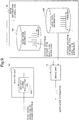
- a noise suppressing apparatus 600 as the sixth exemplary embodiment of the present invention will be described using Fig. 10 .
- the noise suppressing apparatus 600 according to this exemplary embodiment is different in a point that a modification unit 7 is provided between the noise information storage unit 6 and the mixing unit 11. Because the other structures are the same as those of the first exemplary embodiment, a same number is attached to a same structure here, and description will be omitted.
- the modification unit 7 modifies noise information by multiplying a scaling factor that is based on an enhanced signal magnitude spectrum as a noise suppression result supplied from the noise suppression unit 3, and supplies it to the mixing unit 11 as modified noise information.
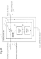
- Fig. 11 is a block diagram showing an internal configuration of the modification unit 7.
- the modification unit 7 Corresponding to the number of noise information stored in the noise information storage unit 6, the modification unit 7 has a plurality of modified noise information generating units 71-7n.
- the modification unit 7 in a case where only one piece of noise information is stored, it should also be equipped with only one modified noise information generating unit.
- Each of the modified noise information generating units 71-7n includes a multiplier 711, a memory unit 712 and an update unit 713. Noise information supplied to the modification unit 7 is then supplied to the multiplier 711.
- the memory unit 712 stores a scaling factor as information for modification used when noise information is modified.
- the multiplier 711 obtains a product of the noise information and the scaling factor, and outputs it as modified noise information.
- enhanced signal magnitude spectrum is supplied to the update unit 713 as a noise suppression result.
- the update unit 713 reads the scaling factor in the memory unit 712, changes the scaling factor using the noise suppression result, and supplies the new scaling factor after the change to the memory unit 712.
- the memory unit 712 newly stores the new scaling factor in place of the old scaling factor stored until then.
- the update unit 713 updates the scaling factor so that the larger a noise suppression result without a target signal is (the larger the residual noise is), the larger the modified noise information becomes. This is because a large noise suppression result without the target signal indicates insufficient suppression, and thus it is desired to make the modified noise information large by changing the scaling factor.
- the modified noise information is large, a numerical value to be subtracted will be large in SS method. Therefore, a noise suppression result becomes small.
- MMSE STSA method a small suppression coefficient is obtained because an estimated signal to noise ratio used for calculation of a suppression coefficient becomes small. This brings stronger noise suppression.
- a method to update a scaling factor a plurality of methods can be thought. As an example, a recalculation method and a sequential update method will be described.
- the modification unit 7 can recalculate the scaling factor or update it sequentially so that the noise may be suppressed completely. This is because, when magnitude or power of a noisy signal is small, there is a high probability that the power of signals other than the noise to be suppressed is also small.
- the modification unit 7 can detect that the magnitude or power of a noisy signal is small using a comparison result that the magnitude or power of the noisy signal is smaller than a threshold value.
- the modification unit 7 can also detect that the magnitude or power of a noisy signal is small by a fact that a difference between the magnitude or power of a noisy signal and noise information recorded in the noise information storage unit 6 is smaller than a threshold value. That is, when the magnitude or power of the noisy signal resembles the noise information, the modification unit 7 utilizes that the share of the noise information in the noisy signal is high (the signal to noise ratio is low). In particular, by using information at a plurality of frequency points in a combined manner, it becomes possible for the modification unit 7 to compare spectral envelopes and make a highly accurate detection.
- a scaling factor for the SS method is recalculated so that, in each frequency, modified noise information becomes equal to a noisy signal spectrum when a target signal is absent.
- the modification unit 7 calculates the scaling factor ⁇ n so that a noisy signal magnitude spectrum
- n is a frame index and k is a frequency index. That is, a scaling factor ⁇ n(k) is calculated by the following equation (8).
- ⁇ n k Yn k / ⁇ n k
- a scaling factor is updated, in each frequency, a little bit at a time so that an enhanced signal magnitude spectrum when a target signal is absent should approach zero.
- the modification unit 7 calculates ⁇ n+1(k) by the following equation (9) using an error en(k) in frequency k and in frame n.
- ⁇ n + 1 k ⁇ n k + ⁇ en k / ⁇ n k ⁇ is a small constant called a step size.
- the modification unit 7 uses the following equation (10) instead of the equation (9).
- ⁇ n k ⁇ n ⁇ 1 k + ⁇ en k / ⁇ n k
- the modification unit 7 calculates the current scaling factor ⁇ n(k) using the current error, and apply it immediately. By updating the scaling factor immediately, the modification unit 7 can realize noise suppression with high accuracy in real time.
- the scaling factor ⁇ n+1(k) is calculated by the following equation (11) using the above-mentioned error en (k).
- the modification unit 7 may calculate the scaling factor ⁇ n+1(k) by the following Equation (12) using a perturbation method.
- ⁇ n + 1 k ⁇ n k + ⁇ en k
- the modification unit 7 may calculate the scaling factor ⁇ n+1(k) by the following Equation (13) using a signum function sgn ⁇ en (k) ⁇ which represents only the sign of the error.
- ⁇ n + 1 k ⁇ n k + ⁇ sgn en k
- the modification unit 7 may use the LS (Least Squares) algorithm or any other adaptation algorithm.
- the modification unit 7 can also apply the updated scaling factor immediately, or may perform real time update of the scaling factor by referring to a change from equations (9) to (10) to modify equations (11) to (13).
- the MMSE STSA method updates a scaling factor sequentially.
- the modification unit 7 updates the scaling factor ⁇ n(k) using the same method as the method described using the mathematical expressions (8) to (13).
- the modification unit 7 can change an updating method such as using the sequential update method in the beginning and using the recalculation method later.
- the modification unit 7 may use if the scaling factor sufficiently close to the optimum value as a condition.
- the modification unit 7 may change the updating method when a predetermined time has elapsed, for example. Otherwise, the modification unit 7 may change the updating method when a modification amount of the scaling factor has become smaller than a predetermined threshold value.
- noise information used for noise suppression when noise information used for noise suppression is modified, information for modification used for the modification is updated based on a noise suppression result. Consequently, various kinds of noise including unknown noise can be suppressed without storing a large number of noise information in advance.
- the modification unit 7 may modify the mixing ratio of noise information.
- the modification unit 7 can achieve the same effect as this exemplary embodiment by modifying the mixing ratios ⁇ 1- ⁇ n shown in Fig. 8 , for example.
- a noise suppressing apparatus as the seventh exemplary embodiment of the present invention will be described using Fig. 12 .
- the noise suppressing apparatus according to this exemplary embodiment is different in a point that a suppression result analysis unit 70 is provided in the modification unit 7. Because the other structures are the same as those of the sixth exemplary embodiment, a same number is attached to a same structure here, and description will be omitted.
- the suppression result analysis unit 70 analyzes a suppression result, and modifies the scaling factor according to the amount of the residual in a plurality of noise information. As a result, the modification unit 7 can modify noise information having a large residual relatively aggressively among each of a plurality of noise information.
- a noise suppressing apparatus as the eighth exemplary embodiment of the present invention will be described using Fig. 13 .
- the sixth exemplary embodiment has been described taking an example in which a scaling factor is used as information for modification for modifying a noise signal, an example in which a numerical value made by adding an offset to a scaling factor is made information for modification in this exemplary embodiment. In this case, both of the scaling factor and the offset are updated based on a noise suppression result.
- Fig. 13 is a block diagram showing an internal configuration of the modification unit 7.
- the modification unit 7 According to the number of noise information stored in the noise information storage unit 6, the modification unit 7 has a plurality of modified noise information generating units 71-7n. Of course, when only one piece of noise information is stored as shown in Fig. 5 , only one modified noise information generating unit should be provided.
- each of the modified noise information generating units 71-7n includes an adder unit 714, a memory unit 715 and an update unit 716 in addition to the structure shown in Fig. 11 . Because the operations of the multiplier 711, the memory unit 712 and the update unit 713 has been described using Fig. 11 , description will be omitted here.
- the multiplier 711 multiplies supplied noise information by a scaling factor read from the memory unit 712, and supplies the product to the adder unit 714.
- the adder unit 714 subtracts an offset value stored in the memory unit 715 from the output of the multiplier 711, and outputs the result as modified noise information.
- the same noise suppression result as the update unit 713 is supplied to the update unit 716, and the offset value stored in the memory unit 715 is updated using the noise suppression result, and the new offset value is supplied to the memory unit 715.
- the memory unit 715 newly stores the new offset value in place of the old offset value which have been stored until then.
- a scaling factor and an offset are employed as information for modification used for modification of noise information. Therefore, noise information can be modified more finely, and, as a result, the noise suppression effect can be improved.
- a noise suppressing apparatus as the ninth exemplary embodiment of the present invention will be described using Fig. 14 .
- the noise suppressing apparatus according to this exemplary embodiment is different in a point that the modification unit 7 has the suppression result analysis unit 70. Because the other structures are the same as those of the eighth exemplary embodiment, a same number is attached to a same structure, and description will be omitted here.
- the suppression result analysis unit 70 a suppression result is analyzed, and the offset is corrected according to which noise information has a large remaining non-suppressed amount.
- the modification unit 7 can modify noise information having a large residual relatively aggressively among each of a plurality of noise information.
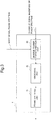
- the tenth exemplary embodiment of the present invention will be described using Fig. 15 .
- information (noise existence information) which indicates whether specific noise exists in an inputted noisy signal or not is supplied from an input terminal 9. With this information, noise can be suppressed certainly when the specific noise exists. Because other structures and operations are the same as those of the first exemplary embodiment, description will be omitted here.
- the eleventh exemplary embodiment of the present invention will be described using Fig. 16 .
- information (noise existence information) which indicates whether specific noise exists in an inputted noisy signal or not is supplied from the input terminal 9.
- the information for modification is not updated when the specific noise does not exist. Therefore, the accuracy of noise suppression for the specific noise can be improved.
- a noise suppressing apparatus 1200 in this exemplary embodiment has a target signal existence judgment unit 81.
- a noisy signal magnitude spectrum from the transformation unit 2 is transmitted to the target signal existence judgment unit 81.
- the target signal existence judgment unit 81 analyzes the noisy signal magnitude spectrum and judges whether a target signal exists or not, or how much it exists.
- a modification unit 87 updates the information for modification for modifying noise information based on the judgment result by the target signal existence judgment unit 81. For example, because, when there is no target signal, the noisy signal is entirely composed of noise, a suppression result by the noise suppression unit 3 should be zero. Accordingly, the modification unit 87 adjusts a scaling factor and the like so that a noise suppression result at that time should be zero.
- update of the information for modification in the modification unit 87 is performed according to the existence rate of the target signal. For example, when a target signal exists in the noisy signal with a rate of 10%, the information for modification is updated partially (by 90%).
- noise suppressing apparatus each having a specific feature
- noise suppressing apparatus made by any combination of those features is also included within the category of the present invention.
- the present invention may be applied to a system composed of a plurality of equipment or single equipment. Further, the present invention is also applicable in a case where a signal processing software program which realizes the functions of the exemplary embodiments is supplied to a system or equipment directly or remotely. Accordingly, a program installed in a computer in order to realize the functions of the present invention by a computer, a medium storing such a program and a WWW server storing the program for download are also included within the category of the present invention.
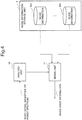
- Fig. 18 is a block diagram of a computer 1800 which executes a signal processing program when the first exemplary embodiment is formed by the signal processing program.
- the computer 1800 includes an input unit 1801, a CPU 1802, a noise information storage unit 1803, an output unit 1804, a memory 1805 and a communication control unit 1806.
- the CPU 1802 controls operations of the whole computer 1800. That is, the CPU 1802 that has executed the signal processing program analyzes a noisy signal and determines a mixing method (S1821). Next, the CPU 1802 mixes a plurality of noise information by the determined mixing method, and generates mixed noise information (S1822). At least one of the plurality of noise information to be mixed is information stored in the noise information storage unit 1803 in advance. Next, the CPU 1802 suppresses noise in the noisy signal using the mixed noise information (S1823), and completes the processing.
Landscapes
- Engineering & Computer Science (AREA)
- Computational Linguistics (AREA)
- Quality & Reliability (AREA)
- Signal Processing (AREA)
- Health & Medical Sciences (AREA)
- Audiology, Speech & Language Pathology (AREA)
- Human Computer Interaction (AREA)
- Physics & Mathematics (AREA)
- Acoustics & Sound (AREA)
- Multimedia (AREA)
- Noise Elimination (AREA)
Claims (17)
- Audiosignalverarbeitungsverfahren, das aufweist:Analysieren eines verrauschten Audiosignals, das als ein Eingangssignal zugeführt wird;Erzeugen von gemischten Rauschinformationen durch Mischen von mehreren Rauschinformationen über eine Art eines bekannten Rauschens, das unterdrückt werden soll und in einem Speicher im Voraus gespeichert wird, mit einem Verfahren, das beruhend auf dem Ergebnis der Analyse des verrauschten Audiosignals festgelegt wird; undUnterdrücken der einen Art des bekannten Rauschens mittels der gemischten Rauschinformationen.
- Audiosignalverarbeitungsverfahren nach Anspruch 1, das ferner aufweist:Mischen als die Rauschinformationen eines mittleren Spektrums und eines maximalen Spektrums der einen Art des bekannten Rauschens, das unterdrückt werden soll, um die gemischten Rauschinformationen zu erzeugen.
- Audiosignalverarbeitungsverfahren nach Anspruch 1, das ferner aufweist:Mischen als die Rauschinformationen eines mittleren Spektrums, eines maximalen Spektrums und eines minimalen Spektrums der einen Art des bekannten Rauschens, das unterdrückt werden soll, um die gemischten Rauschinformationen zu erzeugen.
- Audiosignalverarbeitungsverfahren nach Anspruch 2 oder 3, das ferner aufweist:Speichern des mittleren Spektrums der einen Art des bekannten Rauschens, das unterdrückt werden soll, im Voraus im Speicher; undErzeugen des maximalen Spektrums aus dem mittleren Spektrum.
- Audiosignalverarbeitungsverfahren nach Anspruch 3, das ferner aufweist:Speichern des mittleren Spektrums der einen Art des bekannten Rauschens, das unterdrückt werden soll, im Voraus im Speicher; undErzeugen des minimalen Spektrums aus dem mittleren Spektrum.
- Audiosignalverarbeitungsverfahren nach einem der Ansprüche 1 bis 5, das ferner aufweist:bei der Detektion einer Spitzenkomponente durch Analysieren des verrauschten Audiosignals,Erzeugen der gemischten Rauschinformationen durch Mischen aus Frequenzkomponenten des Rauschens, das unterdrückt werden soll, der Spitzenkomponente und anderer Grundkomponenten als die Spitzenkomponente der mehreren Rauschinformationen.
- Audiosignalverarbeitungsverfahren nach einem der Ansprüche 1 bis 6, das ferner aufweist:Erzeugen der gemischten Rauschinformationen durch Multiplizieren jeder der zu mischenden mehreren Rauschinformationen mit einem Koeffizienten gemäß dem Analyseergebnis des verrauschten Audiosignals, und dann Mischen jedes Produkts des Koeffizienten und der mehreren Rauschinformationen.
- Audiosignalverarbeitungsverfahren nach einem der Ansprüche 1 bis 7, das ferner aufweist:Speichern spezieller Rauschinformationen, die eine spezielle Spektralform aufweisen, im Voraus im Speicher;durch Analyse des verrauschten Audiosignals, Bewerten eine Ähnlichkeit zwischen den speziellen Rauschinformationen und dem verrauschten Eingangsaudiosignal; undbei der Detektion eines hohen Ähnlichkeitsgrads, Mischen der speziellen Rauschinformationen, um die gemischten Rauschinformationen zu erzeugen.
- Audiosignalverarbeitungsverfahren nach Anspruch 8, wobei die speziellen Rauschinformationen Trittschallinformationen sind.
- Audiosignalverarbeitungsverfahren nach einem der Ansprüche 1 bis 9, das ferner aufweist:Modifizieren der Rauschinformationen beruhend auf einem Rauschunterdrückungsergebnis.
- Audiosignalverarbeitungsverfahren nach Anspruch 10, das ferner aufweist:Modifizieren der Rauschinformationen durch Multiplizieren der Rauschinformationen mit einem Skalierungsfaktor, der dem Rauschunterdrückungsergebnis entspricht.
- Audiosignalverarbeitungsverfahren nach Anspruch 10 oder 11, das ferner aufweist:Modifizieren der Rauschinformationen durch Einführen eines Offsets, der dem Rauschunterdrückungsergebnis entspricht.
- Audiosignalverarbeitungsverfahren nach einem der Ansprüche 10 bis 12, das ferner aufweist:beruhend auf einem Ergebnis der Analyse des Rauschunterdrückungsergebnisses, Modifizieren jeder der mehreren zu mischenden Rauschinformationen.
- Audiosignalverarbeitungsverfahren nach einem der Ansprüche 1 bis 13, das ferner aufweist:Zuführen von Informationen über das Vorhandensein von Rauschen im verrauschten Audiosignal; und,beim Vorhandensein des Rauschens im verrauschten Audiosignal, Unterdrücken des Rauschens.
- Audiosignalverarbeitungsverfahren nach einem der Ansprüche 1 bis 14, das ferner aufweist:durch Analysieren des verrauschten Audiosignals, Feststellen wie viel des Sollsignals im verrauschten Audiosignal vorhanden ist, und Unterdrücken des Rauschens beruhend auf dem Feststellungsergebnis.
- Audioinformationsverarbeitungsvorrichtung, die aufweist:ein Analysemittel zum Analysieren eines verrauschten Audiosignals, das als ein Eingangssignal zugeführt wird;ein Erzeugungsmittel zum Erzeugen von gemischten Rauschinformationen durch Mischen von mehreren Rauschinformationen über eine Art eines bekannten Rauschens, das unterdrückt werden soll und in einem Speicher im Voraus gespeichert wird, mit einem Verfahren, das beruhend auf dem Ergebnis der Analyse des verrauschten Audiosignals festgelegt wird; undein Rauschunterdrückungsmittel zum Unterdrücken der einen Art des bekannten Rauschens mittels der gemischten Rauschinformationen.
- Programmaufzeichnungsmedium, das ein Audiosignalverarbeitungsprogramm speichert, um einen Computer zu veranlassen, einen Prozess auszuführen, der die Schritte aufweist:Analysieren eines verrauschten Audiosignals, das als ein Eingangssignal zugeführt wird;Erzeugen von gemischten Rauschinformationen durch Mischen von mehreren Rauschinformationen über eine Art eines bekannten Rauschens, das unterdrückt werden soll und in einem Speicher im Voraus gespeichert wird, mit einem Verfahren, das beruhend auf dem Ergebnis der Analyse des verrauschten Audiosignals festgelegt wird; undUnterdrücken der einen Art des bekannten Rauschens mittels der gemischten Rauschinformationen.
Applications Claiming Priority (2)
| Application Number | Priority Date | Filing Date | Title |
|---|---|---|---|
| JP2010118842 | 2010-05-24 | ||
| PCT/JP2011/061597 WO2011148860A1 (ja) | 2010-05-24 | 2011-05-13 | 信号処理方法、情報処理装置、及び信号処理プログラム |
Publications (3)
| Publication Number | Publication Date |
|---|---|
| EP2579254A1 EP2579254A1 (de) | 2013-04-10 |
| EP2579254A4 EP2579254A4 (de) | 2014-07-02 |
| EP2579254B1 true EP2579254B1 (de) | 2017-07-12 |
Family
ID=45003850
Family Applications (1)
| Application Number | Title | Priority Date | Filing Date |
|---|---|---|---|
| EP11786559.2A Active EP2579254B1 (de) | 2010-05-24 | 2011-05-13 | Signalverarbeitungsverfahren, informationsverarbeitungsvorrichtung und signalverarbeitungsprogramm |
Country Status (5)
| Country | Link |
|---|---|
| US (1) | US9837097B2 (de) |
| EP (1) | EP2579254B1 (de) |
| JP (1) | JP5867389B2 (de) |
| CN (1) | CN102906813A (de) |
| WO (1) | WO2011148860A1 (de) |
Families Citing this family (13)
| Publication number | Priority date | Publication date | Assignee | Title |
|---|---|---|---|---|
| WO2012097148A2 (en) * | 2011-01-12 | 2012-07-19 | Personics Holdings, Inc. | Automotive constant signal-to-noise ratio system for enhanced situation awareness |
| JP5768450B2 (ja) * | 2011-03-31 | 2015-08-26 | 富士通株式会社 | 騒音推定装置及び騒音推定プログラム |
| WO2014126213A1 (ja) * | 2013-02-15 | 2014-08-21 | Necソリューションイノベータ株式会社 | 類似判断の候補配列情報の選択装置、選択方法、およびそれらの用途 |
| JP6226065B2 (ja) | 2014-05-19 | 2017-11-08 | 日本電気株式会社 | ソーナー装置、信号処理方法及びプログラム |
| US10149047B2 (en) * | 2014-06-18 | 2018-12-04 | Cirrus Logic Inc. | Multi-aural MMSE analysis techniques for clarifying audio signals |
| US10746838B2 (en) | 2014-11-10 | 2020-08-18 | Nec Corporation | Signal processing apparatus, signal processing method, and signal processing program |
| JP6541179B2 (ja) * | 2015-04-02 | 2019-07-10 | 日本電気株式会社 | 信号処理装置 |
| KR20170051856A (ko) * | 2015-11-02 | 2017-05-12 | 주식회사 아이티매직 | 사운드 신호에서 진단 신호를 추출하는 방법 및 진단 장치 |
| US11296739B2 (en) * | 2016-12-22 | 2022-04-05 | Nuvoton Technology Corporation Japan | Noise suppression device, noise suppression method, and reception device and reception method using same |
| TWI646842B (zh) * | 2017-09-11 | 2019-01-01 | 晨星半導體股份有限公司 | 應用於顯示裝置的電路及相關的訊號處理方法 |
| JP2019192963A (ja) * | 2018-04-18 | 2019-10-31 | オリンパス株式会社 | ノイズ軽減装置、ノイズ軽減方法およびプログラム |
| KR102327441B1 (ko) * | 2019-09-20 | 2021-11-17 | 엘지전자 주식회사 | 인공지능 장치 |
| CN111294066B (zh) * | 2020-01-16 | 2022-04-12 | Oppo广东移动通信有限公司 | 一种信号处理方法、接收机及计算机存储介质 |
Family Cites Families (28)
| Publication number | Priority date | Publication date | Assignee | Title |
|---|---|---|---|---|
| JP3451146B2 (ja) | 1995-02-17 | 2003-09-29 | 株式会社日立製作所 | スペクトルサブトラクションを用いた雑音除去システムおよび方法 |
| WO1997010586A1 (en) | 1995-09-14 | 1997-03-20 | Ericsson Inc. | System for adaptively filtering audio signals to enhance speech intelligibility in noisy environmental conditions |
| JP3452443B2 (ja) * | 1996-03-25 | 2003-09-29 | 三菱電機株式会社 | 騒音下音声認識装置及び騒音下音声認識方法 |
| DE69939796D1 (de) * | 1998-07-16 | 2008-12-11 | Matsushita Electric Ind Co Ltd | Lärmkontrolleanordnung |
| US6519559B1 (en) | 1999-07-29 | 2003-02-11 | Intel Corporation | Apparatus and method for the enhancement of signals |
| JP3454206B2 (ja) * | 1999-11-10 | 2003-10-06 | 三菱電機株式会社 | 雑音抑圧装置及び雑音抑圧方法 |
| US20030179888A1 (en) | 2002-03-05 | 2003-09-25 | Burnett Gregory C. | Voice activity detection (VAD) devices and methods for use with noise suppression systems |
| JP4282227B2 (ja) | 2000-12-28 | 2009-06-17 | 日本電気株式会社 | ノイズ除去の方法及び装置 |
| JP2002236497A (ja) | 2001-02-08 | 2002-08-23 | Alpine Electronics Inc | ノイズリダクションシステム |
| JP2002258897A (ja) * | 2001-02-27 | 2002-09-11 | Fujitsu Ltd | 雑音抑圧装置 |
| JP2002314637A (ja) * | 2001-04-09 | 2002-10-25 | Denso Corp | 雑音低減装置 |
| JP3457293B2 (ja) * | 2001-06-06 | 2003-10-14 | 三菱電機株式会社 | 雑音抑圧装置及び雑音抑圧方法 |
| JP2003284181A (ja) * | 2002-03-20 | 2003-10-03 | Matsushita Electric Ind Co Ltd | 集音装置 |
| JP2009282536A (ja) * | 2003-05-30 | 2009-12-03 | National Institute Of Advanced Industrial & Technology | 既知音響信号除去方法及び装置 |
| US7224810B2 (en) * | 2003-09-12 | 2007-05-29 | Spatializer Audio Laboratories, Inc. | Noise reduction system |
| JP2006262241A (ja) * | 2005-03-18 | 2006-09-28 | Casio Comput Co Ltd | 電子カメラ、ノイズ低減装置及びノイズ低減制御プログラム |
| JP2006279185A (ja) | 2005-03-28 | 2006-10-12 | Casio Comput Co Ltd | 撮像装置、音声記録方法及びプログラム |
| JP4765461B2 (ja) * | 2005-07-27 | 2011-09-07 | 日本電気株式会社 | 雑音抑圧システムと方法及びプログラム |
| WO2007026691A1 (ja) | 2005-09-02 | 2007-03-08 | Nec Corporation | 雑音抑圧の方法及び装置並びにコンピュータプログラム |
| JP4245617B2 (ja) * | 2006-04-06 | 2009-03-25 | 株式会社東芝 | 特徴量補正装置、特徴量補正方法および特徴量補正プログラム |
| JP4316583B2 (ja) * | 2006-04-07 | 2009-08-19 | 株式会社東芝 | 特徴量補正装置、特徴量補正方法および特徴量補正プログラム |
| US20100110231A1 (en) * | 2007-04-13 | 2010-05-06 | Panasonic Corporation | Output control circuit and imaging device |
| US8189766B1 (en) * | 2007-07-26 | 2012-05-29 | Audience, Inc. | System and method for blind subband acoustic echo cancellation postfiltering |
| KR101444100B1 (ko) * | 2007-11-15 | 2014-09-26 | 삼성전자주식회사 | 혼합 사운드로부터 잡음을 제거하는 방법 및 장치 |
| CN102160358B (zh) * | 2008-09-19 | 2015-03-11 | 杜比实验室特许公司 | 小蜂窝无线网络中的客户设备的上游信号处理 |
| JP5068240B2 (ja) | 2008-11-12 | 2012-11-07 | 日本電信電話株式会社 | 光伝送方式、送信器及び受信器 |
| US8798992B2 (en) * | 2010-05-19 | 2014-08-05 | Disney Enterprises, Inc. | Audio noise modification for event broadcasting |
| JP5788873B2 (ja) * | 2010-05-25 | 2015-10-07 | 日本電気株式会社 | 信号処理方法、情報処理装置、及び信号処理プログラム |
-
2011
- 2011-05-13 CN CN2011800255734A patent/CN102906813A/zh active Pending
- 2011-05-13 JP JP2012517234A patent/JP5867389B2/ja active Active
- 2011-05-13 WO PCT/JP2011/061597 patent/WO2011148860A1/ja active Application Filing
- 2011-05-13 US US13/698,345 patent/US9837097B2/en active Active
- 2011-05-13 EP EP11786559.2A patent/EP2579254B1/de active Active
Non-Patent Citations (1)
| Title |
|---|
| None * |
Also Published As
| Publication number | Publication date |
|---|---|
| EP2579254A4 (de) | 2014-07-02 |
| CN102906813A (zh) | 2013-01-30 |
| EP2579254A1 (de) | 2013-04-10 |
| JP5867389B2 (ja) | 2016-02-24 |
| JPWO2011148860A1 (ja) | 2013-07-25 |
| WO2011148860A1 (ja) | 2011-12-01 |
| US9837097B2 (en) | 2017-12-05 |
| US20130064392A1 (en) | 2013-03-14 |
Similar Documents
| Publication | Publication Date | Title |
|---|---|---|
| EP2579254B1 (de) | Signalverarbeitungsverfahren, informationsverarbeitungsvorrichtung und signalverarbeitungsprogramm | |
| US7478041B2 (en) | Speech recognition apparatus, speech recognition apparatus and program thereof | |
| US10811026B2 (en) | Noise suppression method, device, and program | |
| US9047874B2 (en) | Noise suppression method, device, and program | |
| EP2500902B1 (de) | Signalverarbeitungsverfahren, informationsprozessor und signalverarbeitungsprogramm | |
| EP2767978B1 (de) | Unterdrückung des rauschens in einem verschlechterten audiosignal | |
| EP2645368B1 (de) | Signalverarbeitungsvorrichtung, signalverarbeitungsverfahren und signalverarbeitungsprogramm | |
| CN103229236A (zh) | 信号处理装置、信号处理方法、及信号处理程序 | |
| EP2498252B1 (de) | Informationsverarbeitungsvorrichtung, hilfsvorrichtung dafür, informationsverarbeitungssystem, steuerverfahren dafür und steuerprogramm | |
| EP2645738B1 (de) | Signalverarbeitungsvorrichtung, signalverarbeitungsverfahren und signalverarbeitungsprogramm | |
| EP2498253B1 (de) | Unterdrückung des rauschens in einem verrauschten audiosignal | |
| US9190070B2 (en) | Signal processing method, information processing apparatus, and storage medium for storing a signal processing program |
Legal Events
| Date | Code | Title | Description |
|---|---|---|---|
| PUAI | Public reference made under article 153(3) epc to a published international application that has entered the european phase |
Free format text: ORIGINAL CODE: 0009012 |
|
| 17P | Request for examination filed |
Effective date: 20121212 |
|
| AK | Designated contracting states |
Kind code of ref document: A1 Designated state(s): AL AT BE BG CH CY CZ DE DK EE ES FI FR GB GR HR HU IE IS IT LI LT LU LV MC MK MT NL NO PL PT RO RS SE SI SK SM TR |
|
| DAX | Request for extension of the european patent (deleted) | ||
| REG | Reference to a national code |
Ref country code: DE Ref legal event code: R079 Ref document number: 602011039544 Country of ref document: DE Free format text: PREVIOUS MAIN CLASS: G10L0021020000 Ipc: G10L0021020800 |
|
| A4 | Supplementary search report drawn up and despatched |
Effective date: 20140530 |
|
| RIC1 | Information provided on ipc code assigned before grant |
Ipc: G10L 21/0208 20130101AFI20140523BHEP |
|
| 17Q | First examination report despatched |
Effective date: 20150713 |
|
| GRAP | Despatch of communication of intention to grant a patent |
Free format text: ORIGINAL CODE: EPIDOSNIGR1 |
|
| INTG | Intention to grant announced |
Effective date: 20170209 |
|
| GRAS | Grant fee paid |
Free format text: ORIGINAL CODE: EPIDOSNIGR3 |
|
| GRAA | (expected) grant |
Free format text: ORIGINAL CODE: 0009210 |
|
| AK | Designated contracting states |
Kind code of ref document: B1 Designated state(s): AL AT BE BG CH CY CZ DE DK EE ES FI FR GB GR HR HU IE IS IT LI LT LU LV MC MK MT NL NO PL PT RO RS SE SI SK SM TR |
|
| REG | Reference to a national code |
Ref country code: GB Ref legal event code: FG4D |
|
| REG | Reference to a national code |
Ref country code: CH Ref legal event code: EP |
|
| REG | Reference to a national code |
Ref country code: AT Ref legal event code: REF Ref document number: 909041 Country of ref document: AT Kind code of ref document: T Effective date: 20170715 |
|
| REG | Reference to a national code |
Ref country code: IE Ref legal event code: FG4D |
|
| REG | Reference to a national code |
Ref country code: DE Ref legal event code: R096 Ref document number: 602011039544 Country of ref document: DE |
|
| REG | Reference to a national code |
Ref country code: NL Ref legal event code: MP Effective date: 20170712 |
|
| REG | Reference to a national code |
Ref country code: LT Ref legal event code: MG4D |
|
| REG | Reference to a national code |
Ref country code: AT Ref legal event code: MK05 Ref document number: 909041 Country of ref document: AT Kind code of ref document: T Effective date: 20170712 |
|
| PG25 | Lapsed in a contracting state [announced via postgrant information from national office to epo] |
Ref country code: HR Free format text: LAPSE BECAUSE OF FAILURE TO SUBMIT A TRANSLATION OF THE DESCRIPTION OR TO PAY THE FEE WITHIN THE PRESCRIBED TIME-LIMIT Effective date: 20170712 Ref country code: FI Free format text: LAPSE BECAUSE OF FAILURE TO SUBMIT A TRANSLATION OF THE DESCRIPTION OR TO PAY THE FEE WITHIN THE PRESCRIBED TIME-LIMIT Effective date: 20170712 Ref country code: NO Free format text: LAPSE BECAUSE OF FAILURE TO SUBMIT A TRANSLATION OF THE DESCRIPTION OR TO PAY THE FEE WITHIN THE PRESCRIBED TIME-LIMIT Effective date: 20171012 Ref country code: NL Free format text: LAPSE BECAUSE OF FAILURE TO SUBMIT A TRANSLATION OF THE DESCRIPTION OR TO PAY THE FEE WITHIN THE PRESCRIBED TIME-LIMIT Effective date: 20170712 Ref country code: AT Free format text: LAPSE BECAUSE OF FAILURE TO SUBMIT A TRANSLATION OF THE DESCRIPTION OR TO PAY THE FEE WITHIN THE PRESCRIBED TIME-LIMIT Effective date: 20170712 Ref country code: LT Free format text: LAPSE BECAUSE OF FAILURE TO SUBMIT A TRANSLATION OF THE DESCRIPTION OR TO PAY THE FEE WITHIN THE PRESCRIBED TIME-LIMIT Effective date: 20170712 Ref country code: SE Free format text: LAPSE BECAUSE OF FAILURE TO SUBMIT A TRANSLATION OF THE DESCRIPTION OR TO PAY THE FEE WITHIN THE PRESCRIBED TIME-LIMIT Effective date: 20170712 |
|
| PG25 | Lapsed in a contracting state [announced via postgrant information from national office to epo] |
Ref country code: RS Free format text: LAPSE BECAUSE OF FAILURE TO SUBMIT A TRANSLATION OF THE DESCRIPTION OR TO PAY THE FEE WITHIN THE PRESCRIBED TIME-LIMIT Effective date: 20170712 Ref country code: ES Free format text: LAPSE BECAUSE OF FAILURE TO SUBMIT A TRANSLATION OF THE DESCRIPTION OR TO PAY THE FEE WITHIN THE PRESCRIBED TIME-LIMIT Effective date: 20170712 Ref country code: BG Free format text: LAPSE BECAUSE OF FAILURE TO SUBMIT A TRANSLATION OF THE DESCRIPTION OR TO PAY THE FEE WITHIN THE PRESCRIBED TIME-LIMIT Effective date: 20171012 Ref country code: LV Free format text: LAPSE BECAUSE OF FAILURE TO SUBMIT A TRANSLATION OF THE DESCRIPTION OR TO PAY THE FEE WITHIN THE PRESCRIBED TIME-LIMIT Effective date: 20170712 Ref country code: PL Free format text: LAPSE BECAUSE OF FAILURE TO SUBMIT A TRANSLATION OF THE DESCRIPTION OR TO PAY THE FEE WITHIN THE PRESCRIBED TIME-LIMIT Effective date: 20170712 Ref country code: IS Free format text: LAPSE BECAUSE OF FAILURE TO SUBMIT A TRANSLATION OF THE DESCRIPTION OR TO PAY THE FEE WITHIN THE PRESCRIBED TIME-LIMIT Effective date: 20171112 Ref country code: GR Free format text: LAPSE BECAUSE OF FAILURE TO SUBMIT A TRANSLATION OF THE DESCRIPTION OR TO PAY THE FEE WITHIN THE PRESCRIBED TIME-LIMIT Effective date: 20171013 |
|
| REG | Reference to a national code |
Ref country code: DE Ref legal event code: R097 Ref document number: 602011039544 Country of ref document: DE |
|
| PG25 | Lapsed in a contracting state [announced via postgrant information from national office to epo] |
Ref country code: DK Free format text: LAPSE BECAUSE OF FAILURE TO SUBMIT A TRANSLATION OF THE DESCRIPTION OR TO PAY THE FEE WITHIN THE PRESCRIBED TIME-LIMIT Effective date: 20170712 Ref country code: CZ Free format text: LAPSE BECAUSE OF FAILURE TO SUBMIT A TRANSLATION OF THE DESCRIPTION OR TO PAY THE FEE WITHIN THE PRESCRIBED TIME-LIMIT Effective date: 20170712 Ref country code: RO Free format text: LAPSE BECAUSE OF FAILURE TO SUBMIT A TRANSLATION OF THE DESCRIPTION OR TO PAY THE FEE WITHIN THE PRESCRIBED TIME-LIMIT Effective date: 20170712 |
|
| PLBE | No opposition filed within time limit |
Free format text: ORIGINAL CODE: 0009261 |
|
| STAA | Information on the status of an ep patent application or granted ep patent |
Free format text: STATUS: NO OPPOSITION FILED WITHIN TIME LIMIT |
|
| PG25 | Lapsed in a contracting state [announced via postgrant information from national office to epo] |
Ref country code: SK Free format text: LAPSE BECAUSE OF FAILURE TO SUBMIT A TRANSLATION OF THE DESCRIPTION OR TO PAY THE FEE WITHIN THE PRESCRIBED TIME-LIMIT Effective date: 20170712 Ref country code: SM Free format text: LAPSE BECAUSE OF FAILURE TO SUBMIT A TRANSLATION OF THE DESCRIPTION OR TO PAY THE FEE WITHIN THE PRESCRIBED TIME-LIMIT Effective date: 20170712 Ref country code: IT Free format text: LAPSE BECAUSE OF FAILURE TO SUBMIT A TRANSLATION OF THE DESCRIPTION OR TO PAY THE FEE WITHIN THE PRESCRIBED TIME-LIMIT Effective date: 20170712 Ref country code: EE Free format text: LAPSE BECAUSE OF FAILURE TO SUBMIT A TRANSLATION OF THE DESCRIPTION OR TO PAY THE FEE WITHIN THE PRESCRIBED TIME-LIMIT Effective date: 20170712 |
|
| 26N | No opposition filed |
Effective date: 20180413 |
|
| PG25 | Lapsed in a contracting state [announced via postgrant information from national office to epo] |
Ref country code: SI Free format text: LAPSE BECAUSE OF FAILURE TO SUBMIT A TRANSLATION OF THE DESCRIPTION OR TO PAY THE FEE WITHIN THE PRESCRIBED TIME-LIMIT Effective date: 20170712 |
|
| REG | Reference to a national code |
Ref country code: CH Ref legal event code: PL |
|
| GBPC | Gb: european patent ceased through non-payment of renewal fee |
Effective date: 20180513 |
|
| REG | Reference to a national code |
Ref country code: BE Ref legal event code: MM Effective date: 20180531 |
|
| PG25 | Lapsed in a contracting state [announced via postgrant information from national office to epo] |
Ref country code: MC Free format text: LAPSE BECAUSE OF FAILURE TO SUBMIT A TRANSLATION OF THE DESCRIPTION OR TO PAY THE FEE WITHIN THE PRESCRIBED TIME-LIMIT Effective date: 20170712 |
|
| REG | Reference to a national code |
Ref country code: IE Ref legal event code: MM4A |
|
| PG25 | Lapsed in a contracting state [announced via postgrant information from national office to epo] |
Ref country code: LI Free format text: LAPSE BECAUSE OF NON-PAYMENT OF DUE FEES Effective date: 20180531 Ref country code: CH Free format text: LAPSE BECAUSE OF NON-PAYMENT OF DUE FEES Effective date: 20180531 |
|
| PG25 | Lapsed in a contracting state [announced via postgrant information from national office to epo] |
Ref country code: LU Free format text: LAPSE BECAUSE OF NON-PAYMENT OF DUE FEES Effective date: 20180513 |
|
| PG25 | Lapsed in a contracting state [announced via postgrant information from national office to epo] |
Ref country code: IE Free format text: LAPSE BECAUSE OF NON-PAYMENT OF DUE FEES Effective date: 20180513 Ref country code: GB Free format text: LAPSE BECAUSE OF NON-PAYMENT OF DUE FEES Effective date: 20180513 Ref country code: FR Free format text: LAPSE BECAUSE OF NON-PAYMENT OF DUE FEES Effective date: 20180531 |
|
| PG25 | Lapsed in a contracting state [announced via postgrant information from national office to epo] |
Ref country code: BE Free format text: LAPSE BECAUSE OF NON-PAYMENT OF DUE FEES Effective date: 20180531 |
|
| PG25 | Lapsed in a contracting state [announced via postgrant information from national office to epo] |
Ref country code: MT Free format text: LAPSE BECAUSE OF NON-PAYMENT OF DUE FEES Effective date: 20180513 |
|
| PG25 | Lapsed in a contracting state [announced via postgrant information from national office to epo] |
Ref country code: TR Free format text: LAPSE BECAUSE OF FAILURE TO SUBMIT A TRANSLATION OF THE DESCRIPTION OR TO PAY THE FEE WITHIN THE PRESCRIBED TIME-LIMIT Effective date: 20170712 |
|
| PG25 | Lapsed in a contracting state [announced via postgrant information from national office to epo] |
Ref country code: HU Free format text: LAPSE BECAUSE OF FAILURE TO SUBMIT A TRANSLATION OF THE DESCRIPTION OR TO PAY THE FEE WITHIN THE PRESCRIBED TIME-LIMIT; INVALID AB INITIO Effective date: 20110513 Ref country code: PT Free format text: LAPSE BECAUSE OF FAILURE TO SUBMIT A TRANSLATION OF THE DESCRIPTION OR TO PAY THE FEE WITHIN THE PRESCRIBED TIME-LIMIT Effective date: 20170712 |
|
| PG25 | Lapsed in a contracting state [announced via postgrant information from national office to epo] |
Ref country code: MK Free format text: LAPSE BECAUSE OF NON-PAYMENT OF DUE FEES Effective date: 20170712 Ref country code: CY Free format text: LAPSE BECAUSE OF FAILURE TO SUBMIT A TRANSLATION OF THE DESCRIPTION OR TO PAY THE FEE WITHIN THE PRESCRIBED TIME-LIMIT Effective date: 20170712 |
|
| PG25 | Lapsed in a contracting state [announced via postgrant information from national office to epo] |
Ref country code: AL Free format text: LAPSE BECAUSE OF FAILURE TO SUBMIT A TRANSLATION OF THE DESCRIPTION OR TO PAY THE FEE WITHIN THE PRESCRIBED TIME-LIMIT Effective date: 20170712 |
|
| PGFP | Annual fee paid to national office [announced via postgrant information from national office to epo] |
Ref country code: DE Payment date: 20230519 Year of fee payment: 13 |