EP2579117A2 - Verfahren zur Anpassung der Ursprungsposition einer Maschine, und Maschine mit einer Funktion zur Anpassung der Ursprungsposition - Google Patents
Verfahren zur Anpassung der Ursprungsposition einer Maschine, und Maschine mit einer Funktion zur Anpassung der Ursprungsposition Download PDFInfo
- Publication number
- EP2579117A2 EP2579117A2 EP12005463.0A EP12005463A EP2579117A2 EP 2579117 A2 EP2579117 A2 EP 2579117A2 EP 12005463 A EP12005463 A EP 12005463A EP 2579117 A2 EP2579117 A2 EP 2579117A2
- Authority
- EP
- European Patent Office
- Prior art keywords
- reference counter
- origin
- machine
- adjusting
- counter
- Prior art date
- Legal status (The legal status is an assumption and is not a legal conclusion. Google has not performed a legal analysis and makes no representation as to the accuracy of the status listed.)
- Granted
Links
Images

Classifications
-
- G—PHYSICS
- G05—CONTROLLING; REGULATING
- G05B—CONTROL OR REGULATING SYSTEMS IN GENERAL; FUNCTIONAL ELEMENTS OF SUCH SYSTEMS; MONITORING OR TESTING ARRANGEMENTS FOR SUCH SYSTEMS OR ELEMENTS
- G05B19/00—Program-control systems
- G05B19/02—Program-control systems electric
- G05B19/18—Numerical control [NC], i.e. automatically operating machines, in particular machine tools, e.g. in a manufacturing environment, so as to execute positioning, movement or co-ordinated operations by means of program data in numerical form
- G05B19/404—Numerical control [NC], i.e. automatically operating machines, in particular machine tools, e.g. in a manufacturing environment, so as to execute positioning, movement or co-ordinated operations by means of program data in numerical form characterised by control arrangements for compensation, e.g. for backlash, overshoot, tool offset, tool wear, temperature, machine construction errors, load, inertia
-
- G—PHYSICS
- G05—CONTROLLING; REGULATING
- G05B—CONTROL OR REGULATING SYSTEMS IN GENERAL; FUNCTIONAL ELEMENTS OF SUCH SYSTEMS; MONITORING OR TESTING ARRANGEMENTS FOR SUCH SYSTEMS OR ELEMENTS
- G05B2219/00—Program-control systems
- G05B2219/30—Nc systems
- G05B2219/37—Measurements
- G05B2219/37153—Encoder delivers only one channel of pulses, using only one detector
-
- G—PHYSICS
- G05—CONTROLLING; REGULATING
- G05B—CONTROL OR REGULATING SYSTEMS IN GENERAL; FUNCTIONAL ELEMENTS OF SUCH SYSTEMS; MONITORING OR TESTING ARRANGEMENTS FOR SUCH SYSTEMS OR ELEMENTS
- G05B2219/00—Program-control systems
- G05B2219/30—Nc systems
- G05B2219/50—Machine tool, machine tool null till machine tool work handling
- G05B2219/50025—Go to reference, switches and dog detect origin, combine with pulse from encoder
Definitions
- This invention relates to a method of adjusting the position of origin for validating the mechanical origin in a machine having a moving part driven by a servo motor, such as machine tool, electrical discharge machine tool, injection-forming machine, robot or industrial machine, and to a machine having a function for adjusting the position of origin.
- a servo motor such as machine tool, electrical discharge machine tool, injection-forming machine, robot or industrial machine
- a workpiece is often fixed to a predetermined position by using a jig.
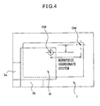
- Fig. 4 is a top view of a workpiece and peripheral equipment. As shown in Fig. 4 , a workpiece W of the shape of a flat plate is placed on a workpiece-placing plate 1. The workpiece W is fixed by using two jigs 2a and 2b so will not to move in the X- and Y-directions. Further, it is presumed that the workpiece-placing plate 1 is mounted on a machine having a moving part that is driven by the servo motor.
- a machining-start hole of a predetermined shape has been formed in the workpiece W at a predetermined position.
- the machining-start hole is also called workpiece origin OW.
- workpiece origin OW as a reference, dimensions for machining the workpiece W are specified by the drawings and the like.
- the data of position (positional difference) between the workpiece origin OW and a mechanical origin OM are registered as a workpiece coordinate system in advance.
- the mechanical origin OM set in the workpiece-placing plate 1 of Fig. 4 is maintained when the servo motor (not shown) of the machine is being connected to a control unit (not shown) and the power source is maintained alive. However, when assembling or transferring the machine or when the power source for maintaining the data, such as a dry cell, is depleted, the data of the mechanical origin OM are no longer present or are often erased.
- the mechanical origin OM must be set.
- a concrete method of setting the mechanical origin OM has been disclosed in, for example, Japanese Unexamined Patent Publication No. 62-95604 .
- the mechanical origin OM is not an arbitrary position but is determined depending on a relative position between the moving part such as shaft (not shown) of the machine and the fixed portion such as workpiece-placing plate 1. Further, in order that the mechanical origin OM can be more correctly set irrespective of the skill of a worker, the mechanical origin OM is set by using a one-rotation signal of a pulse coder. Usually, the position dependent upon the one-rotation signal of the pulse coder does not correctly represent the position of mechanical origin OM and, therefore, the position of mechanical origin OM must be adjusted.
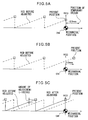
- Figs. 5A to 5C are diagrams illustrating the action for adjusting the position of mechanical origin OM according to a prior art.
- the abscissas represent the position of the machine and the ordinates represent the data RCD of a reference counter.
- the reference counter operates as a reversible counter and outputs a grid signal for every input of a predetermined amount of pulses related to a position on the abscissa.
- the reference counter has a counter capacity CCD of 50,000 and if a pulse at a position on the abscissa has a weight that is set to 0.01 ⁇ m, then a grid data is produced for every 500,000 distribution pulses, i.e., for every moving amount of 5 mm.
- the reference counter If the data RCD of the reference counter reaches a predetermined value that corresponds to one rotation of a pulse coder attached to the motor, the reference counter outputs a one-rotation signal (represented by white squares in Figs. 5A to 5C ).
- a value of the reference counter before adjusted is represented by a broken line.
- a plurality of vertexes on the broken line represents one-rotation signals of the pulse coder.
- the present invention was accomplished in view of the above-mentioned circumstances and has an object of providing a method of adjusting the position of origin of a machine, which is capable of more easily setting the position of origin while shortening the time for working operations and a machine having a function for adjusting the position of origin.
- a method of adjusting the position of mechanical origin of a machine having a moving part that is driven by a servo motor equipped with a position detector comprising the steps of moving the moving part in a predetermined direction to position it at the position of mechanical origin, reading a value of a reference counter that counts the value detected by the position detector at a moment when the moving part is positioned, reading a counter capacity of the reference counter, and calculating the amount of adjusting the position of mechanical origin based on the value of the reference counter of when the moving part is positioned and on the capacity of the reference counter is provided.
- the machine is a machine tool, an electric discharge machine tool, an injection-forming machine, an industrial machine or a robot.
- a machine having a function for adjusting the position of mechanical origin of a moving part that is driven by a servo motor equipped with a position detector, comprising a reference counter for counting the value detected by the position detector, a storage unit for storing the capacity of the reference counter of when the moving part is moved in a predetermined direction and is positioned at the position of mechanical origin, a reference counter reading unit for reading the value of the reference counter of when the moving part is positioned, a counter capacity reading unit for reading the counter capacity of the reference counter, and an adjustment amount calculation unit for calculating the amount of adjusting the position of mechanical origin based on the value of the reference counter and on the capacity of the reference counter is provided.
- the machine is a machine tool, an electric discharge machine tool, an injection-forming machine, an industrial machine or a robot.
- Fig. 1 is a functional block diagram of a machine based on the present invention.
- a servo motor M is used for driving a mechanism-moving part 10 of the machine such as machine tool, electric discharge machine tool, injection-forming machine, robot or industrial machine.
- the moving amount of the mechanism-moving part 10 is determined depending upon the amount of rotation of the shaft of the servo motor M.
- a CNC 11 produces a motion command value for the shaft of the servo motor M.
- the servo motor M is provided with a pulse coder 15 which detects the position of the shaft of the servo motor M for every predetermined control period.
- the position value detected by the pulse coder 15 is subtracted from the motion command value at a subtractor 12, and is input to an error register 13.
- a voltage signal is commanded depending on an amount of error output from the error register 13.
- the voltage signal is amplified through a servo amplifier 14 and is input to the servo motor M.
- the position value detected by the pulse coder 15 is also input to a reference counter 16.
- the counter capacity data CCD of the reference counter 16 is stored in a storage unit 17 of the CNC 11.
- the reference counter 16 counts the position value detected by the pulse coder 15 and updates the reference counter data RCD.
- a grid signal is output as the reference counter data RCD reaches a predetermined amount.
- the grid is an electronic grid point produced by a counter that uses, as an initial value, a value that is set for a parameter with reference to the one-rotation signal produced for every rotation of the pulse coder 15 (position detector).
- the counter capacity data CCD of the reference counter 16 is presumed to be 500,000 and the weight of one pulse is presumed to be 0.01 ⁇ m.
- the grid signal is output for every 500,000 distribution pulses, i.e., for every moving amount of 5 mm.
- the reference counter produces a one-rotation signal.
- the reference counter data RCD of the reference counter 16 is read by the counter reading unit 18 and is input to a calculation unit 20. Based on the reference counter data RCD and the counter capacity data CCD, the calculation unit 20 calculates the amount of adjusting the position of mechanical origin in a manner as described below.
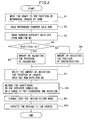
- Fig. 2 is a flowchart for illustrating a method of adjusting the position of origin of the machine based on the present invention.
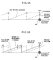
- Figs. 3A and 3B are diagrams for illustrating the action for adjusting the position of mechanical origin OM based on the present invention.
- the abscissas represent the mechanical position and the ordinates represent the data RCD of the reference counter. Further, in these drawings, the one-rotation signals are represented by white squares.
- the machine inclusive of the mechanism-moving part 10 is provided with a workpiece W and a workpiece-placing plate 1.
- the workpiece W of the shape of a flat plate is placed on the workpiece-placing plate 1.
- the workpiece W is fixed by two jigs 2a and 2b so will not to move in the XY-directions.
- the workpiece-placing plate 1 is attached to the machine having the moving part that is driven by the servo motor.
- a machining-start hole of a predetermined shape has been formed in the workpiece W at a predetermined position.
- the machining-start hole is also called workpiece origin OW.
- workpiece origin OW as a reference, dimensions for machining the workpiece W are specified by the drawings and the like.
- the data of position (positional difference) between the workpiece origin OW and the mechanical origin OM are registered as a workpiece coordinate system in advance. Described below with reference to Fig. 1 to Fig. 3B is the method of adjusting the position of origin of the machine based upon the present invention.
- step S1 the operator moves the shaft of the machine to the position of mechanical origin OM by hand.
- the reference counter data RCD is read from the reference counter 16 through the counter reading unit 18 and, at the same time, the counter capacity data CCD is read from the storage unit 17 through the counter capacity reading unit 19 (steps S2 and S3).
- the reference counter data RCD is 400,000 and the counter capacity data CCD is 500,000.
- the calculation unit 20 judges if the reference counter data RCD is smaller than one-half the counter capacity data CCD. This is because it is desired that the amount of adjustment is set with the one-rotation signal as a center. Therefore, if the reference counter data RCD exceeds one-half the counter capacity data CCD, then the method of calculation is better differed to advantage. Further, one-half the counter capacity data CCD is compared with the reference counter data RCD because of the reason that the amount of adjustment may often be quickly calculated if the judgment is rendered based on the next reference counter data RCD.
- the amount of adjusting the position of origin is set to the reference counter data RCD (step S5).
- the reference counter data RCD is not smaller than one-half the counter capacity data CCD, a deviation obtained by subtracting the counter capacity data CCD from the reference counter data RCD is set as the amount of adjusting the position of origin (step S6).
- step S7 the amount of adjusting the position of origin that is set is written into the ROM data for NC (not shown). Thereafter, the shaft is returned back in the opposite direction in a range of not exceeding one rotation, the shaft is moved in the origin return mode, and the origin is set at the position of one rotation of the motor.
- the present position (white circle) comes in agreement with the one-rotation signal (white square). Since the amount of adjusting the position of origin has been set as described above, the value of the reference counter 16 becomes zero when the origin is set.
- the amount of adjusting the position of origin is set based on the mechanical position (abscissa).
- the amount of adjusting the position of origin is set based on the reference counter data RCD (ordinate). Therefore, the working time for setting the mechanical position can be shortened, and the position of origin OM can be set more easily. Further, it will be understood that the work for setting the position of origin OM can be conducted irrespective of the skill of the operator.
- the amount of adjusting the position of origin is set based on the reference counter data. Therefore, the working time for setting the mechanical position can be shortened, and the position of origin can be more easily set.
- the invention can be applied to many kinds of machines.
Landscapes
- Engineering & Computer Science (AREA)
- Human Computer Interaction (AREA)
- Manufacturing & Machinery (AREA)
- Physics & Mathematics (AREA)
- General Physics & Mathematics (AREA)
- Automation & Control Theory (AREA)
- Numerical Control (AREA)
- Manipulator (AREA)
- Control Of Position Or Direction (AREA)
Applications Claiming Priority (1)
| Application Number | Priority Date | Filing Date | Title |
|---|---|---|---|
| JP2011223216A JP5226843B2 (ja) | 2011-10-07 | 2011-10-07 | 機械における原点位置調整方法および原点位置調整機能を有する機械 |
Publications (3)
| Publication Number | Publication Date |
|---|---|
| EP2579117A2 true EP2579117A2 (de) | 2013-04-10 |
| EP2579117A3 EP2579117A3 (de) | 2013-06-19 |
| EP2579117B1 EP2579117B1 (de) | 2015-07-01 |
Family
ID=47048915
Family Applications (1)
| Application Number | Title | Priority Date | Filing Date |
|---|---|---|---|
| EP12005463.0A Active EP2579117B1 (de) | 2011-10-07 | 2012-07-26 | Verfahren zur Anpassung der Ursprungsposition einer Maschine, und Maschine mit einer Funktion zur Anpassung der Ursprungsposition |
Country Status (4)
| Country | Link |
|---|---|
| US (1) | US9348330B2 (de) |
| EP (1) | EP2579117B1 (de) |
| JP (1) | JP5226843B2 (de) |
| CN (1) | CN103034241B (de) |
Cited By (2)
| Publication number | Priority date | Publication date | Assignee | Title |
|---|---|---|---|---|
| CN105938350A (zh) * | 2015-03-03 | 2016-09-14 | 发那科株式会社 | 使用了绝对位置检测器重建机械坐标值的数值控制装置 |
| CN113703393A (zh) * | 2021-07-12 | 2021-11-26 | 珠海格力电器股份有限公司 | 数控机床的换刀点设定方法及其装置 |
Families Citing this family (4)
| Publication number | Priority date | Publication date | Assignee | Title |
|---|---|---|---|---|
| CN106272430B (zh) * | 2016-09-18 | 2018-12-07 | 珠海格力电器股份有限公司 | 机械手原点复归方法及装置 |
| JP6382911B2 (ja) * | 2016-11-01 | 2018-08-29 | ファナック株式会社 | ワイヤ放電加工機 |
| CN112720485B (zh) * | 2020-12-22 | 2022-08-30 | 深圳市越疆科技有限公司 | 机械臂关节回零方法、装置及计算机可读存储介质 |
| CN114281026A (zh) * | 2021-12-31 | 2022-04-05 | 昆山顺之晟精密机械有限公司 | 一种利用plc的脉冲计数功能保持线切割系统绝对原点的方法 |
Citations (1)
| Publication number | Priority date | Publication date | Assignee | Title |
|---|---|---|---|---|
| JPS6295604A (ja) | 1985-10-22 | 1987-05-02 | Fanuc Ltd | 数値制御工作機械の機械原点設定方法 |
Family Cites Families (9)
| Publication number | Priority date | Publication date | Assignee | Title |
|---|---|---|---|---|
| US3843915A (en) * | 1973-02-02 | 1974-10-22 | Ncr Co | Servo-motor control system including a two phase digital shaft position detector |
| JP2525849B2 (ja) * | 1988-02-24 | 1996-08-21 | ファナック株式会社 | 原点復帰方法 |
| JPH0283708A (ja) * | 1988-09-21 | 1990-03-23 | Nissan Motor Co Ltd | 移動体の座標原点設定方法 |
| JPH0332551A (ja) | 1989-06-29 | 1991-02-13 | Fanuc Ltd | 機械原点オフセット調整方法 |
| JP2811087B2 (ja) | 1989-08-22 | 1998-10-15 | ファナック株式会社 | 原点復帰装置 |
| US5465036A (en) * | 1992-12-11 | 1995-11-07 | Canon Kabushiki Kaisha | Control apparatus of robot |
| JPH06332533A (ja) | 1993-05-25 | 1994-12-02 | Hitachi Seiki Co Ltd | マーカ方式原点復帰調整装置およびその方法 |
| WO2003060616A1 (en) * | 2002-01-17 | 2003-07-24 | Mitsubishi Denki Kabushiki Kaisha | Method and device for numerical control |
| JP4261563B2 (ja) * | 2006-09-08 | 2009-04-30 | ファナック株式会社 | 加工原点設定方法及びその方法を実施するための工作機械 |
-
2011
- 2011-10-07 JP JP2011223216A patent/JP5226843B2/ja not_active Expired - Fee Related
-
2012
- 2012-07-26 EP EP12005463.0A patent/EP2579117B1/de active Active
- 2012-08-15 US US13/585,946 patent/US9348330B2/en active Active
- 2012-08-27 CN CN201210308687.6A patent/CN103034241B/zh not_active Expired - Fee Related
Patent Citations (1)
| Publication number | Priority date | Publication date | Assignee | Title |
|---|---|---|---|---|
| JPS6295604A (ja) | 1985-10-22 | 1987-05-02 | Fanuc Ltd | 数値制御工作機械の機械原点設定方法 |
Cited By (4)
| Publication number | Priority date | Publication date | Assignee | Title |
|---|---|---|---|---|
| CN105938350A (zh) * | 2015-03-03 | 2016-09-14 | 发那科株式会社 | 使用了绝对位置检测器重建机械坐标值的数值控制装置 |
| CN105938350B (zh) * | 2015-03-03 | 2017-12-26 | 发那科株式会社 | 使用了绝对位置检测器重建机械坐标值的数值控制装置 |
| US10185300B2 (en) | 2015-03-03 | 2019-01-22 | Fanuc Corporation | Numerical controller reestablishing machine coordinate value by using absolute position detector |
| CN113703393A (zh) * | 2021-07-12 | 2021-11-26 | 珠海格力电器股份有限公司 | 数控机床的换刀点设定方法及其装置 |
Also Published As
| Publication number | Publication date |
|---|---|
| US9348330B2 (en) | 2016-05-24 |
| EP2579117A3 (de) | 2013-06-19 |
| EP2579117B1 (de) | 2015-07-01 |
| JP5226843B2 (ja) | 2013-07-03 |
| CN103034241B (zh) | 2014-10-15 |
| JP2013084102A (ja) | 2013-05-09 |
| US20130090754A1 (en) | 2013-04-11 |
| CN103034241A (zh) | 2013-04-10 |
Similar Documents
| Publication | Publication Date | Title |
|---|---|---|
| EP2579117B1 (de) | Verfahren zur Anpassung der Ursprungsposition einer Maschine, und Maschine mit einer Funktion zur Anpassung der Ursprungsposition | |
| EP3470772B1 (de) | Baumaschine | |
| EP3105016B1 (de) | Verfahren zum automatischen kalibrierung für robotersysteme mittels eines sichtsensors | |
| US20140297022A1 (en) | Numerically-controlled machine tool and spindle error compensating method thereof | |
| US7899577B2 (en) | Measuring system and calibration method | |
| EP2042278B1 (de) | Robotersteuerung zum Halten eines Roboters auf der Basis der Geschwindigkeit eines Roboterhandteils | |
| EP2047955A2 (de) | Einstellvorrichtung für Roboterbetriebsbereich | |
| CN105377513A (zh) | 具有视觉的自动机加工头及方法 | |
| CN106346315A (zh) | 能够取得工件原点的机床控制系统以及工件原点设定方法 | |
| US20110029131A1 (en) | Apparatus and method for measuring tool center point position of robot | |
| EP1676679A2 (de) | Robotische Steuereinheit zur Positionskorrektur einer Roboterhand mittels einem optischen Sensor | |
| CN109085802B (zh) | 电动机的控制装置 | |
| CN109085801B (zh) | 电动机的控制装置 | |
| US11567470B2 (en) | Computer-aided optimization of numerically controlled machining of a workpiece | |
| US10948899B2 (en) | Motor controller that uses an acceleration/deceleration time constant of the motor | |
| US20210132571A1 (en) | System and method for machine workpiece alignment | |
| CN109954955B (zh) | 机器人系统 | |
| EP1886771B1 (de) | Verfahren zur berechnung eines rotationsmittelpunktes, verfahren zur berechnung einer rotationsachse, verfahren zur erstellung eines programms, betriebsverfahren und robotergerät | |
| CN107357258B (zh) | 具有碰撞应力释放装置的机床的碰撞检测装置 | |
| EP3229089A1 (de) | System zur steuerung der position eines werkzeugs und verfahren zur steuerung der position dieses werkzeugs | |
| US8150545B2 (en) | Position-dependent compliance compensation in a machine tool | |
| US10474122B2 (en) | Machining tool with numerical control device | |
| RU109036U1 (ru) | Устройство компенсации угловых смещений осей инструмента и обрабатываемого отверстия | |
| KR20130074033A (ko) | 공작기계의 이송축 오버트래블 제어방법 | |
| JP2731268B2 (ja) | 折曲機のストッパ位置演算装置 |
Legal Events
| Date | Code | Title | Description |
|---|---|---|---|
| PUAI | Public reference made under article 153(3) epc to a published international application that has entered the european phase |
Free format text: ORIGINAL CODE: 0009012 |
|
| AK | Designated contracting states |
Kind code of ref document: A2 Designated state(s): AL AT BE BG CH CY CZ DE DK EE ES FI FR GB GR HR HU IE IS IT LI LT LU LV MC MK MT NL NO PL PT RO RS SE SI SK SM TR |
|
| AX | Request for extension of the european patent |
Extension state: BA ME |
|
| REG | Reference to a national code |
Ref country code: DE Ref legal event code: R079 Ref document number: 602012008292 Country of ref document: DE Free format text: PREVIOUS MAIN CLASS: G05B0019401000 Ipc: G05B0019404000 |
|
| PUAL | Search report despatched |
Free format text: ORIGINAL CODE: 0009013 |
|
| 17P | Request for examination filed |
Effective date: 20130419 |
|
| AK | Designated contracting states |
Kind code of ref document: A3 Designated state(s): AL AT BE BG CH CY CZ DE DK EE ES FI FR GB GR HR HU IE IS IT LI LT LU LV MC MK MT NL NO PL PT RO RS SE SI SK SM TR |
|
| AX | Request for extension of the european patent |
Extension state: BA ME |
|
| RIC1 | Information provided on ipc code assigned before grant |
Ipc: G05B 19/404 20060101AFI20130516BHEP |
|
| RBV | Designated contracting states (corrected) |
Designated state(s): AL AT BE BG CH CY CZ DE DK EE ES FI FR GB GR HR HU IE IS IT LI LT LU LV MC MK MT NL NO PL PT RO RS SE SI SK SM TR |
|
| 17Q | First examination report despatched |
Effective date: 20140212 |
|
| GRAP | Despatch of communication of intention to grant a patent |
Free format text: ORIGINAL CODE: EPIDOSNIGR1 |
|
| INTG | Intention to grant announced |
Effective date: 20150225 |
|
| GRAS | Grant fee paid |
Free format text: ORIGINAL CODE: EPIDOSNIGR3 |
|
| GRAA | (expected) grant |
Free format text: ORIGINAL CODE: 0009210 |
|
| AK | Designated contracting states |
Kind code of ref document: B1 Designated state(s): AL AT BE BG CH CY CZ DE DK EE ES FI FR GB GR HR HU IE IS IT LI LT LU LV MC MK MT NL NO PL PT RO RS SE SI SK SM TR |
|
| REG | Reference to a national code |
Ref country code: GB Ref legal event code: FG4D |
|
| REG | Reference to a national code |
Ref country code: AT Ref legal event code: REF Ref document number: 734317 Country of ref document: AT Kind code of ref document: T Effective date: 20150715 Ref country code: CH Ref legal event code: EP |
|
| REG | Reference to a national code |
Ref country code: IE Ref legal event code: FG4D |
|
| REG | Reference to a national code |
Ref country code: DE Ref legal event code: R096 Ref document number: 602012008292 Country of ref document: DE |
|
| REG | Reference to a national code |
Ref country code: CH Ref legal event code: NV Representative=s name: BUGNION S.A., CH |
|
| REG | Reference to a national code |
Ref country code: AT Ref legal event code: MK05 Ref document number: 734317 Country of ref document: AT Kind code of ref document: T Effective date: 20150701 |
|
| REG | Reference to a national code |
Ref country code: NL Ref legal event code: MP Effective date: 20150701 |
|
| REG | Reference to a national code |
Ref country code: LT Ref legal event code: MG4D |
|
| PG25 | Lapsed in a contracting state [announced via postgrant information from national office to epo] |
Ref country code: LT Free format text: LAPSE BECAUSE OF FAILURE TO SUBMIT A TRANSLATION OF THE DESCRIPTION OR TO PAY THE FEE WITHIN THE PRESCRIBED TIME-LIMIT Effective date: 20150701 Ref country code: FI Free format text: LAPSE BECAUSE OF FAILURE TO SUBMIT A TRANSLATION OF THE DESCRIPTION OR TO PAY THE FEE WITHIN THE PRESCRIBED TIME-LIMIT Effective date: 20150701 Ref country code: LV Free format text: LAPSE BECAUSE OF FAILURE TO SUBMIT A TRANSLATION OF THE DESCRIPTION OR TO PAY THE FEE WITHIN THE PRESCRIBED TIME-LIMIT Effective date: 20150701 Ref country code: NO Free format text: LAPSE BECAUSE OF FAILURE TO SUBMIT A TRANSLATION OF THE DESCRIPTION OR TO PAY THE FEE WITHIN THE PRESCRIBED TIME-LIMIT Effective date: 20151001 Ref country code: GR Free format text: LAPSE BECAUSE OF FAILURE TO SUBMIT A TRANSLATION OF THE DESCRIPTION OR TO PAY THE FEE WITHIN THE PRESCRIBED TIME-LIMIT Effective date: 20151002 |
|
| PG25 | Lapsed in a contracting state [announced via postgrant information from national office to epo] |
Ref country code: PL Free format text: LAPSE BECAUSE OF FAILURE TO SUBMIT A TRANSLATION OF THE DESCRIPTION OR TO PAY THE FEE WITHIN THE PRESCRIBED TIME-LIMIT Effective date: 20150701 Ref country code: HR Free format text: LAPSE BECAUSE OF FAILURE TO SUBMIT A TRANSLATION OF THE DESCRIPTION OR TO PAY THE FEE WITHIN THE PRESCRIBED TIME-LIMIT Effective date: 20150701 Ref country code: IS Free format text: LAPSE BECAUSE OF FAILURE TO SUBMIT A TRANSLATION OF THE DESCRIPTION OR TO PAY THE FEE WITHIN THE PRESCRIBED TIME-LIMIT Effective date: 20151101 Ref country code: RS Free format text: LAPSE BECAUSE OF FAILURE TO SUBMIT A TRANSLATION OF THE DESCRIPTION OR TO PAY THE FEE WITHIN THE PRESCRIBED TIME-LIMIT Effective date: 20150701 Ref country code: ES Free format text: LAPSE BECAUSE OF FAILURE TO SUBMIT A TRANSLATION OF THE DESCRIPTION OR TO PAY THE FEE WITHIN THE PRESCRIBED TIME-LIMIT Effective date: 20150701 Ref country code: AT Free format text: LAPSE BECAUSE OF FAILURE TO SUBMIT A TRANSLATION OF THE DESCRIPTION OR TO PAY THE FEE WITHIN THE PRESCRIBED TIME-LIMIT Effective date: 20150701 Ref country code: SE Free format text: LAPSE BECAUSE OF FAILURE TO SUBMIT A TRANSLATION OF THE DESCRIPTION OR TO PAY THE FEE WITHIN THE PRESCRIBED TIME-LIMIT Effective date: 20150701 Ref country code: PT Free format text: LAPSE BECAUSE OF FAILURE TO SUBMIT A TRANSLATION OF THE DESCRIPTION OR TO PAY THE FEE WITHIN THE PRESCRIBED TIME-LIMIT Effective date: 20151102 |
|
| PG25 | Lapsed in a contracting state [announced via postgrant information from national office to epo] |
Ref country code: MC Free format text: LAPSE BECAUSE OF FAILURE TO SUBMIT A TRANSLATION OF THE DESCRIPTION OR TO PAY THE FEE WITHIN THE PRESCRIBED TIME-LIMIT Effective date: 20150701 |
|
| REG | Reference to a national code |
Ref country code: DE Ref legal event code: R097 Ref document number: 602012008292 Country of ref document: DE |
|
| REG | Reference to a national code |
Ref country code: IE Ref legal event code: MM4A |
|
| PG25 | Lapsed in a contracting state [announced via postgrant information from national office to epo] |
Ref country code: SK Free format text: LAPSE BECAUSE OF FAILURE TO SUBMIT A TRANSLATION OF THE DESCRIPTION OR TO PAY THE FEE WITHIN THE PRESCRIBED TIME-LIMIT Effective date: 20150701 Ref country code: IT Free format text: LAPSE BECAUSE OF FAILURE TO SUBMIT A TRANSLATION OF THE DESCRIPTION OR TO PAY THE FEE WITHIN THE PRESCRIBED TIME-LIMIT Effective date: 20150701 Ref country code: DK Free format text: LAPSE BECAUSE OF FAILURE TO SUBMIT A TRANSLATION OF THE DESCRIPTION OR TO PAY THE FEE WITHIN THE PRESCRIBED TIME-LIMIT Effective date: 20150701 Ref country code: CZ Free format text: LAPSE BECAUSE OF FAILURE TO SUBMIT A TRANSLATION OF THE DESCRIPTION OR TO PAY THE FEE WITHIN THE PRESCRIBED TIME-LIMIT Effective date: 20150701 Ref country code: EE Free format text: LAPSE BECAUSE OF FAILURE TO SUBMIT A TRANSLATION OF THE DESCRIPTION OR TO PAY THE FEE WITHIN THE PRESCRIBED TIME-LIMIT Effective date: 20150701 |
|
| PLBE | No opposition filed within time limit |
Free format text: ORIGINAL CODE: 0009261 |
|
| STAA | Information on the status of an ep patent application or granted ep patent |
Free format text: STATUS: NO OPPOSITION FILED WITHIN TIME LIMIT |
|
| PG25 | Lapsed in a contracting state [announced via postgrant information from national office to epo] |
Ref country code: RO Free format text: LAPSE BECAUSE OF FAILURE TO SUBMIT A TRANSLATION OF THE DESCRIPTION OR TO PAY THE FEE WITHIN THE PRESCRIBED TIME-LIMIT Effective date: 20150701 |
|
| 26N | No opposition filed |
Effective date: 20160404 |
|
| PG25 | Lapsed in a contracting state [announced via postgrant information from national office to epo] |
Ref country code: IE Free format text: LAPSE BECAUSE OF NON-PAYMENT OF DUE FEES Effective date: 20150726 |
|
| PG25 | Lapsed in a contracting state [announced via postgrant information from national office to epo] |
Ref country code: SI Free format text: LAPSE BECAUSE OF FAILURE TO SUBMIT A TRANSLATION OF THE DESCRIPTION OR TO PAY THE FEE WITHIN THE PRESCRIBED TIME-LIMIT Effective date: 20150701 |
|
| REG | Reference to a national code |
Ref country code: FR Ref legal event code: ST Effective date: 20160810 |
|
| PG25 | Lapsed in a contracting state [announced via postgrant information from national office to epo] |
Ref country code: FR Free format text: LAPSE BECAUSE OF NON-PAYMENT OF DUE FEES Effective date: 20150901 |
|
| PG25 | Lapsed in a contracting state [announced via postgrant information from national office to epo] |
Ref country code: BE Free format text: LAPSE BECAUSE OF FAILURE TO SUBMIT A TRANSLATION OF THE DESCRIPTION OR TO PAY THE FEE WITHIN THE PRESCRIBED TIME-LIMIT Effective date: 20150701 |
|
| GBPC | Gb: european patent ceased through non-payment of renewal fee |
Effective date: 20160726 |
|
| PG25 | Lapsed in a contracting state [announced via postgrant information from national office to epo] |
Ref country code: MT Free format text: LAPSE BECAUSE OF FAILURE TO SUBMIT A TRANSLATION OF THE DESCRIPTION OR TO PAY THE FEE WITHIN THE PRESCRIBED TIME-LIMIT Effective date: 20150701 |
|
| PG25 | Lapsed in a contracting state [announced via postgrant information from national office to epo] |
Ref country code: HU Free format text: LAPSE BECAUSE OF FAILURE TO SUBMIT A TRANSLATION OF THE DESCRIPTION OR TO PAY THE FEE WITHIN THE PRESCRIBED TIME-LIMIT; INVALID AB INITIO Effective date: 20120726 Ref country code: GB Free format text: LAPSE BECAUSE OF NON-PAYMENT OF DUE FEES Effective date: 20160726 Ref country code: BG Free format text: LAPSE BECAUSE OF FAILURE TO SUBMIT A TRANSLATION OF THE DESCRIPTION OR TO PAY THE FEE WITHIN THE PRESCRIBED TIME-LIMIT Effective date: 20150701 Ref country code: SM Free format text: LAPSE BECAUSE OF FAILURE TO SUBMIT A TRANSLATION OF THE DESCRIPTION OR TO PAY THE FEE WITHIN THE PRESCRIBED TIME-LIMIT Effective date: 20150701 |
|
| PG25 | Lapsed in a contracting state [announced via postgrant information from national office to epo] |
Ref country code: NL Free format text: LAPSE BECAUSE OF FAILURE TO SUBMIT A TRANSLATION OF THE DESCRIPTION OR TO PAY THE FEE WITHIN THE PRESCRIBED TIME-LIMIT Effective date: 20150701 Ref country code: CY Free format text: LAPSE BECAUSE OF FAILURE TO SUBMIT A TRANSLATION OF THE DESCRIPTION OR TO PAY THE FEE WITHIN THE PRESCRIBED TIME-LIMIT Effective date: 20150701 |
|
| PG25 | Lapsed in a contracting state [announced via postgrant information from national office to epo] |
Ref country code: TR Free format text: LAPSE BECAUSE OF FAILURE TO SUBMIT A TRANSLATION OF THE DESCRIPTION OR TO PAY THE FEE WITHIN THE PRESCRIBED TIME-LIMIT Effective date: 20150701 |
|
| PG25 | Lapsed in a contracting state [announced via postgrant information from national office to epo] |
Ref country code: LU Free format text: LAPSE BECAUSE OF NON-PAYMENT OF DUE FEES Effective date: 20150726 |
|
| PG25 | Lapsed in a contracting state [announced via postgrant information from national office to epo] |
Ref country code: MK Free format text: LAPSE BECAUSE OF FAILURE TO SUBMIT A TRANSLATION OF THE DESCRIPTION OR TO PAY THE FEE WITHIN THE PRESCRIBED TIME-LIMIT Effective date: 20150701 |
|
| PG25 | Lapsed in a contracting state [announced via postgrant information from national office to epo] |
Ref country code: AL Free format text: LAPSE BECAUSE OF FAILURE TO SUBMIT A TRANSLATION OF THE DESCRIPTION OR TO PAY THE FEE WITHIN THE PRESCRIBED TIME-LIMIT Effective date: 20150701 |
|
| PGFP | Annual fee paid to national office [announced via postgrant information from national office to epo] |
Ref country code: CH Payment date: 20230801 Year of fee payment: 12 |
|
| PGFP | Annual fee paid to national office [announced via postgrant information from national office to epo] |
Ref country code: DE Payment date: 20230531 Year of fee payment: 12 |
|
| REG | Reference to a national code |
Ref country code: DE Ref legal event code: R119 Ref document number: 602012008292 Country of ref document: DE |
|
| REG | Reference to a national code |
Ref country code: CH Ref legal event code: PL |
|
| PG25 | Lapsed in a contracting state [announced via postgrant information from national office to epo] |
Ref country code: DE Free format text: LAPSE BECAUSE OF NON-PAYMENT OF DUE FEES Effective date: 20250201 |
|
| PG25 | Lapsed in a contracting state [announced via postgrant information from national office to epo] |
Ref country code: CH Free format text: LAPSE BECAUSE OF NON-PAYMENT OF DUE FEES Effective date: 20240731 |