EP2578442A1 - Seat for passenger transport vehicle and vehicles comprising such a seat - Google Patents
Seat for passenger transport vehicle and vehicles comprising such a seat Download PDFInfo
- Publication number
- EP2578442A1 EP2578442A1 EP11184152.4A EP11184152A EP2578442A1 EP 2578442 A1 EP2578442 A1 EP 2578442A1 EP 11184152 A EP11184152 A EP 11184152A EP 2578442 A1 EP2578442 A1 EP 2578442A1
- Authority
- EP
- European Patent Office
- Prior art keywords
- seat
- aisle
- light source
- seats
- vehicle
- Prior art date
- Legal status (The legal status is an assumption and is not a legal conclusion. Google has not performed a legal analysis and makes no representation as to the accuracy of the status listed.)
- Granted
Links
- 230000002093 peripheral effect Effects 0.000 claims description 25
- 239000004020 conductor Substances 0.000 claims description 10
- 239000003086 colorant Substances 0.000 description 1
- 238000005096 rolling process Methods 0.000 description 1
- 230000011664 signaling Effects 0.000 description 1
Images

Classifications
-
- B—PERFORMING OPERATIONS; TRANSPORTING
- B60—VEHICLES IN GENERAL
- B60N—SEATS SPECIALLY ADAPTED FOR VEHICLES; VEHICLE PASSENGER ACCOMMODATION NOT OTHERWISE PROVIDED FOR
- B60N2/00—Seats specially adapted for vehicles; Arrangement or mounting of seats in vehicles
- B60N2/02—Seats specially adapted for vehicles; Arrangement or mounting of seats in vehicles the seat or part thereof being movable, e.g. adjustable
- B60N2/0292—Multiple configuration seats, e.g. for spacious vehicles or mini-buses
-
- B—PERFORMING OPERATIONS; TRANSPORTING
- B60—VEHICLES IN GENERAL
- B60N—SEATS SPECIALLY ADAPTED FOR VEHICLES; VEHICLE PASSENGER ACCOMMODATION NOT OTHERWISE PROVIDED FOR
- B60N2/00—Seats specially adapted for vehicles; Arrangement or mounting of seats in vehicles
- B60N2/24—Seats specially adapted for vehicles; Arrangement or mounting of seats in vehicles for particular purposes or particular vehicles
- B60N2/242—Bus seats
-
- B—PERFORMING OPERATIONS; TRANSPORTING
- B60—VEHICLES IN GENERAL
- B60Q—ARRANGEMENT OF SIGNALLING OR LIGHTING DEVICES, THE MOUNTING OR SUPPORTING THEREOF OR CIRCUITS THEREFOR, FOR VEHICLES IN GENERAL
- B60Q3/00—Arrangement of lighting devices for vehicle interiors; Lighting devices specially adapted for vehicle interiors
- B60Q3/20—Arrangement of lighting devices for vehicle interiors; Lighting devices specially adapted for vehicle interiors for lighting specific fittings of passenger or driving compartments; mounted on specific fittings of passenger or driving compartments
- B60Q3/233—Seats; Arm rests; Head rests
-
- B—PERFORMING OPERATIONS; TRANSPORTING
- B60—VEHICLES IN GENERAL
- B60Q—ARRANGEMENT OF SIGNALLING OR LIGHTING DEVICES, THE MOUNTING OR SUPPORTING THEREOF OR CIRCUITS THEREFOR, FOR VEHICLES IN GENERAL
- B60Q3/00—Arrangement of lighting devices for vehicle interiors; Lighting devices specially adapted for vehicle interiors
- B60Q3/40—Arrangement of lighting devices for vehicle interiors; Lighting devices specially adapted for vehicle interiors specially adapted for specific vehicle types
- B60Q3/41—Arrangement of lighting devices for vehicle interiors; Lighting devices specially adapted for vehicle interiors specially adapted for specific vehicle types for mass transit vehicles, e.g. buses
- B60Q3/44—Spotlighting, e.g. reading lamps
-
- B—PERFORMING OPERATIONS; TRANSPORTING
- B60—VEHICLES IN GENERAL
- B60Q—ARRANGEMENT OF SIGNALLING OR LIGHTING DEVICES, THE MOUNTING OR SUPPORTING THEREOF OR CIRCUITS THEREFOR, FOR VEHICLES IN GENERAL
- B60Q3/00—Arrangement of lighting devices for vehicle interiors; Lighting devices specially adapted for vehicle interiors
- B60Q3/40—Arrangement of lighting devices for vehicle interiors; Lighting devices specially adapted for vehicle interiors specially adapted for specific vehicle types
- B60Q3/41—Arrangement of lighting devices for vehicle interiors; Lighting devices specially adapted for vehicle interiors specially adapted for specific vehicle types for mass transit vehicles, e.g. buses
- B60Q3/46—Emergency lighting, e.g. for escape routes
Definitions
- the present invention relates to a seat for a passenger transport vehicle, comprising a seat portion and a backrest, said backrest comprising an outer lateral edge intended to be adjacent to a passenger circulation aisle.
- Passenger transport vehicle refers to any rolling vehicle including a passenger compartment intended to transport passengers, for example a bus, trolley bus, tramway, train or subway car.
- This type of vehicle generally comprises a plurality of seats distributed in the passenger compartment, for example in two sets adjacent to the two side walls of the vehicle. The seats then define a central path or aisle allowing passengers to circulate.
- the invention therefore aims to resolve these drawbacks, and to allow easier orientation and circulation of passengers in the vehicle.
- the invention relates to a seat of the aforementioned type, characterized in that it comprises at least one light source, arranged near an upper corner of said outer lateral edge, and intended to be oriented toward said aisle.
- the inventive device can comprise one or more of the following features, considered alone or according to all technically possible combinations:
- the invention also relates to a passenger transport vehicle comprising at least one passenger circulation aisle, characterized in that it comprises at least one seat according to the invention, the outer lateral edge of which is adjacent to said aisle, and in that the light source is oriented toward said aisle.
- the invention also relates to a passenger transport vehicle comprising at least one passenger circulation aisle, comprised between two columns of seats adjacent to said aisle, characterized in that the seats of at least one of said columns are seats according to any one of the preceding claims, the outer lateral edge of which is adjacent to said aisle and the light source of which is oriented toward said aisle.
- transverse and “longitudinal” must be understood in relation to the longitudinal travel axis of the passenger transport vehicle.
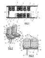
- Figure 1 illustrates a passenger transport vehicle according to one embodiment of the invention.
- the vehicle 1 is for example a bus.
- the passenger compartment 2 of the vehicle comprises two sets 3, 3' of seats arranged on the floor 4 of the vehicle 1 along two longitudinal walls 5 of the vehicle 1.
- the two sets 3 and 3' define an aisle 7 in particular allowing passengers to circulate.
- Each set 3, 3' comprises a plurality of rows 8 of seats facing the front AV or back AR of the vehicle 1, each of the rows 8 being formed by a pair of seats 9, 9'.
- Each pair thus comprises one seat 9 adjacent to the aisle 7, and generally called “aisle seat,” and one seat 9' adjacent to a wall 5, and called “window seat.”
- the seats 9 and 9' are fixed to the chassis frame of a vehicle 1.
- the aisle seats 9 thus form two columns defining the aisle 7.
- Each of the seats 9 comprises a light source 11, arranged near its upper corner oriented toward the aisle 6, and oriented toward the aisle 7.
- the seats 9 thus form a light corridor facilitating passenger circulation in the vehicle 1.
- Figures 2 and 3 show a pair of seats 9, 9' of Figure 1 before mounting in the vehicle 1.
- the pair of seats thus comprises an aisle seat 9 according to one embodiment and a window seat 9', aligned along a transverse axis of the vehicle 1.
- the pair of seats 9, 9' comprises a load-bearing structure 12, comprising a horizontal support beam 13 for the seats 9, 9', base means 14 and fastening means 15 for fastening the beam 13 to a wall of the vehicle.
- the base means 14 are fixed to the beam 12, overhanging the aisle seat 9, and are intended to be fixed 4 to the floor of the vehicle 1.
- the fastening means 15 for example comprise a plate fixed to one end of the beam 12 intended to be fixed to a wall of the vehicle, in a known manner, for example by screws.
- Each seat 9, 9' also comprises a seat portion 16, 16' and a backrest 17, 17', intended to receive a user's body by bearing.
- the aisle seat 9 also comprises an armrest 18.
- the seat portion 16, 16' comprises a seat panel 19, 19' and a peripheral frame 20, 20' surrounding the seat panel 19, 19'.
- the backrest 17, 17' comprises a panel 21, 21' for supporting a user's back and a peripheral frame 22, 22'.
- the support panel 21, 21' which is generally rectangular, comprises two vertical lateral edges 24, 25, a horizontal upper edge 26, a lower edge 27 and two rounded upper corners 28, 29.
- the peripheral frame 22, 22' surrounds the support panel 21, 21' as close as possible thereto.
- the peripheral frame 22, 22' to that end comprises two vertical portions 34, 35, adjacent to the two vertical edges 24, 25, a horizontal upper portion 36, covering the upper edge 26, and two angular portions 38, 39, covering the upper corners 28, 29.
- peripheral frame 22 of the backrest 17 of the aisle seat 9 comprises a first angular portion 38, intended to be adjacent to the aisle of the vehicle, and a second angular portion 39 adjacent to the window seat.
- the peripheral frame 22 is at least partially hollow. It comprises an inner conduit extending from the first angular portion 38, through the vertical portion 34, to a lower end of the peripheral frame 22.
- the vertical portions 34, 35, the upper portions 36 and the angular portions 38, 39 are separate elements, assembled, for example by fitting, to form the peripheral frame 22.
- Each of these elements is hollow and comprises, at both of its ends, an opening allowing the passage of electrical cables.
- the vertical portions 34, 35, the upper portion 36 and the angular portions 38, 39 can be made in a single piece.
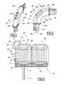
- the first angular portion 38 is provided with a light source 11 intended to be oriented toward the aisle of the vehicle.
- the light source 11 is arranged in the upper corner of the lateral edge 40 of the seatback 17 oriented toward the aisle 7.
- the seat 9 also comprises two electrical conductors that are visible only in Figure 5 with references 54 and 56, and which extend from the light source 11, through the inner conduit of the peripheral frame 22, to a lower end of the peripheral frame 22, then along the beam 13.
- the electrical conductors can be connected to the light source 11 on the one hand, and to an electrical power supply grid of the vehicle on the other hand.
- Figures 4 and 5 are detailed views of the first angular portion 38, hereafter more simply called angular portion 38, and the light source 11.
- the angular portion 38 comprises a tubular central element 42 provided, at a lower end 42a, with a vertical tip 44 and, at an upper end 42b, a horizontal tip 46.
- the vertical tip 44 is adapted to be fitted into the upper end of the vertical portion 34.
- the horizontal tip 46 is adapted to be fitted into the end of the horizontal portion 36 situated on the aisle side.
- the tip 44 has a through opening for the passage of the electrical conductors 54 and 56, which extends from the central element 42 to a lower end of the tip 44.
- the central element 42 is a hollow tube comprising two planar side walls 42c, 42d, respectively oriented toward the front and the back of the seat 9, a lower wall 42e, with surface or linear bearing against the upper corner 28, and an upper wall 42f.
- the section of the lower 42e and upper 42f walls by a plane parallel to the backrest 17 is in the shape of a quarter circle.
- the upper wall 42f has a rounded shape toward the front and the back of the seat 9.
- the central element 42 defines a housing within which the light source 11 is mounted.
- the upper wall 42f is pierced with a through opening 48, which is substantially rectangular, the light source 11 being mounted inside the central element 42 so as to provide light through the opening 48.
- the light source 11 comprises a support plate 50, three light-emitting diodes (LED) 52, fixed to the plate 50, a translucent cover plate 53 and two electrical conductors 54, 56.
- the plate 50, diodes 52 and conductors 54, 56 are shown transparently in Figure 5 .
- the plate 50 is secured to the central element 42. It comprises a substantially rectangular lower wall 50a for supporting the diodes 52, and four side walls protruding from each of the rims of the lower wall to the rims of the opening 48.
- the plate 50 thus defines a substantially parallelepiped housing inside the central element 42.
- the diodes 52 are fastened on the lower wall 50a of the plate 50.
- the diodes 52 are for example RGB LED, i.e. red, green or blue diodes.
- the three diodes 52 are for example the same color, but they can also be different colors, any color combination being possible.
- the two electrical conductors, positive 54 and negative 56 electrically power the diodes 52.
- Said conductors 54, 56 are electrically connected to the two terminals of each of the diodes 52, and extend in the central element 42, then through the through opening of the tip 44, toward the electrical power supply grid of the vehicle.
- the cover plate 53 is intended to diffuse the light emitted by the diodes 52 toward the aisle of the vehicle.
- the cover plate 53 which has a shape combined with the opening 48, comprises three lumps 58 arranged overhanging the diodes 52.
- the cover plate 53 is for example fixed by adhesion to the side walls of the plate 50.
- Figure 6 shows a pair of seats comprising an aisle seat 64 according to a second embodiment of the invention and a window seat 64'.
- elements identical to those of the pair of seats 9, 9' of Figures 1 to 4 bear the same reference numbers.
- the light source 65 of the seat 64 is comprised in an assist grip handle 66, intended to allow the vehicle's passengers to stabilize themselves.
- This handle 66 is mounted on an upper corner of the lateral edge 67 of the backrest 68 of the seat 64 intended to be oriented toward the aisle of the vehicle.
- the backrest 68 of the seat 64 comprises a peripheral frame 69, which differs from the peripheral frame 22 of the seat 9 in that its angular portion 70 does not comprise a light source. It is therefore not provided with an opening comparable to that 48 of the first embodiment.
- the frame 69 supports the assist grip handle 66, which comprises a central portion 72 intended to be gripped by a passenger.
- the central portion 72 is extended at its lower end by a horizontal tubular element 73, fixed to the vertical portion 74 of the frame 69, and a vertical tubular element 76, fixed to the upper portion 78 of the frame 69.
- the central portion 72 of the handle 66 is a hollow tube curved along a central axis in the shape of a quarter circle. It thus defines an inner housing that extends continuously in the vertical portion 74 of the frame 69.
- the central portion 72 comprises the light source 65.
- the light source 65 is for example identical to the light source 11 described in reference to Figures 1 to 4 . It in particular comprises electrical conductors that extend in the central portion 72, then in the vertical portion 74 of the frame 69, toward the electrical power supply grid of the vehicle.
- the invention makes it possible to create a light path in a passenger transport vehicle, at a height close to passengers' eye level.
- a light path guides passengers during their movement in the vehicle, and clearly indicates the position of the seats.
- the light source 11 or 65 is incorporated into an element of the seat 9 or in the immediate vicinity of the seat 64, it does not clutter the passenger compartment of the vehicle 1.
- the seats are seats intended for people with reduced mobility (PRM).
- PRM reduced mobility
- Figure 7 thus shows a passenger transport vehicle 80 according to a third embodiment.
- the vehicle 80 comprises two pairs of PMR seats 82 arranged facing each other.
- the seats 82 of each pair are adjacent on one side to a wall 84 of the vehicle 80 and on another side to an aisle 86 of the vehicle 80.
- the seats 82 are similar to the seat 9 described in reference to Figures 1 to 5 , but are easier to access and larger. They comprise a light source 88, arranged near the upper corner of a lateral edge 89 of their backrest adjacent to the aisle 86, and oriented toward said aisle, therefore easily visible from said aisle.
- the light source 88 is for example blue, characteristic of PRM signaling. It therefore makes it possible to visibly and unambiguously indicate the PRM seat, since it is incorporated into that seat.
- peripheral frame of the backrest of the seat can comprise only an angular portion.
Landscapes
- Engineering & Computer Science (AREA)
- Mechanical Engineering (AREA)
- Aviation & Aerospace Engineering (AREA)
- Transportation (AREA)
- Seats For Vehicles (AREA)
- Chair Legs, Seat Parts, And Backrests (AREA)
Abstract
Description
- The present invention relates to a seat for a passenger transport vehicle, comprising a seat portion and a backrest, said backrest comprising an outer lateral edge intended to be adjacent to a passenger circulation aisle.
- Passenger transport vehicle refers to any rolling vehicle including a passenger compartment intended to transport passengers, for example a bus, trolley bus, tramway, train or subway car. This type of vehicle generally comprises a plurality of seats distributed in the passenger compartment, for example in two sets adjacent to the two side walls of the vehicle. The seats then define a central path or aisle allowing passengers to circulate.
- To signal this aisle and guide passengers in the vehicle, in particular at night, it is known to equip the vehicle with light sources, fixed to the floor or ceiling of the vehicle, and forming two lighted lines on either side of the aisle. Such light sources are also used to indicate seats reserved for people with reduced mobility (PRM). This solution is not fully satisfactory, as it requires passengers to raise or lower their eyes to be guided in the vehicle, therefore to divert their gaze. Furthermore, such light sources do not make it possible to clearly indicate the seats.
- The invention therefore aims to resolve these drawbacks, and to allow easier orientation and circulation of passengers in the vehicle.
- To that end, the invention relates to a seat of the aforementioned type, characterized in that it comprises at least one light source, arranged near an upper corner of said outer lateral edge, and intended to be oriented toward said aisle.
- The inventive device can comprise one or more of the following features, considered alone or according to all technically possible combinations:
- said backrest comprises a support panel for a user's back and a peripheral frame at least partially surrounding said support panel, and said light source is incorporated into said peripheral frame;
- said peripheral frame comprises an angular portion provided with a housing for receiving said light source;
- said angular portion is hollow and pierced with an opening, and said light source is mounted inside said angular portion so as to provide light through the opening;
- said peripheral frame comprises an assist grip handle, intended to allow the vehicle's passengers to stabilize themselves, provided with a housing for receiving said light source;
- said peripheral frame is hollow, and said seat comprises at least two electrical conductors that extend through said peripheral frame and can be connected, on the one hand, to the light source, and on the other hand, to an electrical power supply grid.
- said light source comprises at least one light-emitting diode.
- the seat is intended for a passenger with reduced mobility.
- The invention also relates to a passenger transport vehicle comprising at least one passenger circulation aisle, characterized in that it comprises at least one seat according to the invention, the outer lateral edge of which is adjacent to said aisle, and in that the light source is oriented toward said aisle.
- The invention also relates to a passenger transport vehicle comprising at least one passenger circulation aisle, comprised between two columns of seats adjacent to said aisle, characterized in that the seats of at least one of said columns are seats according to any one of the preceding claims, the outer lateral edge of which is adjacent to said aisle and the light source of which is oriented toward said aisle.
- The invention will be better understood upon reading the following description, provided solely as an example, and done in reference to the appended drawings, in which:
-
Figure 1 is a partial top view, with the roof torn away, of a passenger transport vehicle comprising two columns of seats according to one embodiment of the invention; -
Figure 2 is a perspective view of a pair of seats of the vehicle ofFigure 1 ; -
Figure 3 is a frontal view of the pair of seats ofFigure 2 ; -
Figure 4 is a perspective view of an element of a seat ofFigure 2 ; -
Figure 5 is a frontal view of the element ofFigure 4 ; -
Figure 6 is a frontal view of a pair of seats comprising a seat according to another embodiment of the invention; and -
Figure 7 is a partial top view, with the roof torn away, of a passenger transport vehicle according to another embodiment of the invention. - Hereafter, the chosen orientations are provided for information and are to be understood relative to the figures. In particular, the terms "upper" and "lower" are to be understood relative to the orientation selected in the Figures. These terms are used relative to the orientation of the seats mounted on the chassis frame of the passenger transport vehicle.
- Furthermore, the terms "transverse" and "longitudinal" must be understood in relation to the longitudinal travel axis of the passenger transport vehicle.
-
Figure 1 illustrates a passenger transport vehicle according to one embodiment of the invention. - The vehicle 1 is for example a bus. The
passenger compartment 2 of the vehicle comprises twosets 3, 3' of seats arranged on thefloor 4 of the vehicle 1 along twolongitudinal walls 5 of the vehicle 1. The twosets 3 and 3' define anaisle 7 in particular allowing passengers to circulate. Eachset 3, 3' comprises a plurality ofrows 8 of seats facing the front AV or back AR of the vehicle 1, each of therows 8 being formed by a pair ofseats 9, 9'. - Each pair thus comprises one
seat 9 adjacent to theaisle 7, and generally called "aisle seat," and one seat 9' adjacent to awall 5, and called "window seat." - The
seats 9 and 9' are fixed to the chassis frame of a vehicle 1. - The
aisle seats 9 thus form two columns defining theaisle 7. - Each of the
seats 9 comprises alight source 11, arranged near its upper corner oriented toward the aisle 6, and oriented toward theaisle 7. Theseats 9 thus form a light corridor facilitating passenger circulation in the vehicle 1. -
Figures 2 and 3 show a pair ofseats 9, 9' ofFigure 1 before mounting in the vehicle 1. - The pair of seats thus comprises an
aisle seat 9 according to one embodiment and a window seat 9', aligned along a transverse axis of the vehicle 1. - The pair of
seats 9, 9' comprises a load-bearingstructure 12, comprising ahorizontal support beam 13 for theseats 9, 9', base means 14 and fastening means 15 for fastening thebeam 13 to a wall of the vehicle. - The base means 14 are fixed to the
beam 12, overhanging theaisle seat 9, and are intended to be fixed 4 to the floor of the vehicle 1. The fastening means 15 for example comprise a plate fixed to one end of thebeam 12 intended to be fixed to a wall of the vehicle, in a known manner, for example by screws. - Each
seat 9, 9' also comprises aseat portion 16, 16' and abackrest 17, 17', intended to receive a user's body by bearing. Theaisle seat 9 also comprises anarmrest 18. - The
seat portion 16, 16' comprises aseat panel 19, 19' and aperipheral frame 20, 20' surrounding theseat panel 19, 19'. - The
backrest 17, 17' comprises apanel 21, 21' for supporting a user's back and aperipheral frame 22, 22'. - The
support panel 21, 21', which is generally rectangular, comprises two verticallateral edges upper edge 26, alower edge 27 and two roundedupper corners - The
peripheral frame 22, 22' surrounds thesupport panel 21, 21' as close as possible thereto. Theperipheral frame 22, 22' to that end comprises twovertical portions vertical edges upper portion 36, covering theupper edge 26, and twoangular portions upper corners - In particular, the
peripheral frame 22 of thebackrest 17 of theaisle seat 9 comprises a firstangular portion 38, intended to be adjacent to the aisle of the vehicle, and a secondangular portion 39 adjacent to the window seat. - The
peripheral frame 22 is at least partially hollow. It comprises an inner conduit extending from the firstangular portion 38, through thevertical portion 34, to a lower end of theperipheral frame 22. - The
vertical portions upper portions 36 and theangular portions peripheral frame 22. Each of these elements is hollow and comprises, at both of its ends, an opening allowing the passage of electrical cables. - Alternatively, the
vertical portions upper portion 36 and theangular portions - The first
angular portion 38 is provided with alight source 11 intended to be oriented toward the aisle of the vehicle. Thus, thelight source 11 is arranged in the upper corner of thelateral edge 40 of theseatback 17 oriented toward theaisle 7. - The
seat 9 also comprises two electrical conductors that are visible only inFigure 5 withreferences light source 11, through the inner conduit of theperipheral frame 22, to a lower end of theperipheral frame 22, then along thebeam 13. The electrical conductors can be connected to thelight source 11 on the one hand, and to an electrical power supply grid of the vehicle on the other hand. -
Figures 4 and 5 are detailed views of the firstangular portion 38, hereafter more simply calledangular portion 38, and thelight source 11. - The
angular portion 38 comprises a tubularcentral element 42 provided, at alower end 42a, with avertical tip 44 and, at anupper end 42b, ahorizontal tip 46. - The
vertical tip 44 is adapted to be fitted into the upper end of thevertical portion 34. Thehorizontal tip 46 is adapted to be fitted into the end of thehorizontal portion 36 situated on the aisle side. - Furthermore, the
tip 44 has a through opening for the passage of theelectrical conductors central element 42 to a lower end of thetip 44. - The
central element 42 is a hollow tube comprising twoplanar side walls seat 9, alower wall 42e, with surface or linear bearing against theupper corner 28, and anupper wall 42f. The section of the lower 42e and upper 42f walls by a plane parallel to thebackrest 17 is in the shape of a quarter circle. Furthermore, theupper wall 42f has a rounded shape toward the front and the back of theseat 9. - The
central element 42 defines a housing within which thelight source 11 is mounted. In particular, theupper wall 42f is pierced with a throughopening 48, which is substantially rectangular, thelight source 11 being mounted inside thecentral element 42 so as to provide light through theopening 48. - The
light source 11 comprises asupport plate 50, three light-emitting diodes (LED) 52, fixed to theplate 50, atranslucent cover plate 53 and twoelectrical conductors plate 50,diodes 52 andconductors Figure 5 . - The
plate 50 is secured to thecentral element 42. It comprises a substantially rectangularlower wall 50a for supporting thediodes 52, and four side walls protruding from each of the rims of the lower wall to the rims of theopening 48. Theplate 50 thus defines a substantially parallelepiped housing inside thecentral element 42. - The
diodes 52 are fastened on thelower wall 50a of theplate 50. Thediodes 52 are for example RGB LED, i.e. red, green or blue diodes. The threediodes 52 are for example the same color, but they can also be different colors, any color combination being possible. - The two electrical conductors, positive 54 and negative 56, electrically power the
diodes 52. Saidconductors diodes 52, and extend in thecentral element 42, then through the through opening of thetip 44, toward the electrical power supply grid of the vehicle. - The
cover plate 53 is intended to diffuse the light emitted by thediodes 52 toward the aisle of the vehicle. Thecover plate 53, which has a shape combined with theopening 48, comprises threelumps 58 arranged overhanging thediodes 52. Thecover plate 53 is for example fixed by adhesion to the side walls of theplate 50. -
Figure 6 shows a pair of seats comprising anaisle seat 64 according to a second embodiment of the invention and a window seat 64'. In thisFigure 6 , elements identical to those of the pair ofseats 9, 9' ofFigures 1 to 4 bear the same reference numbers. - In this embodiment, the
light source 65 of theseat 64 is comprised in an assist grip handle 66, intended to allow the vehicle's passengers to stabilize themselves. Thishandle 66 is mounted on an upper corner of thelateral edge 67 of thebackrest 68 of theseat 64 intended to be oriented toward the aisle of the vehicle. - The
backrest 68 of theseat 64 comprises aperipheral frame 69, which differs from theperipheral frame 22 of theseat 9 in that itsangular portion 70 does not comprise a light source. It is therefore not provided with an opening comparable to that 48 of the first embodiment. Theframe 69 supports the assist grip handle 66, which comprises acentral portion 72 intended to be gripped by a passenger. Thecentral portion 72 is extended at its lower end by a horizontaltubular element 73, fixed to thevertical portion 74 of theframe 69, and a verticaltubular element 76, fixed to theupper portion 78 of theframe 69. - The
central portion 72 of thehandle 66 is a hollow tube curved along a central axis in the shape of a quarter circle. It thus defines an inner housing that extends continuously in thevertical portion 74 of theframe 69. - The
central portion 72 comprises thelight source 65. Thelight source 65 is for example identical to thelight source 11 described in reference toFigures 1 to 4 . It in particular comprises electrical conductors that extend in thecentral portion 72, then in thevertical portion 74 of theframe 69, toward the electrical power supply grid of the vehicle. - Done in this way, the invention makes it possible to create a light path in a passenger transport vehicle, at a height close to passengers' eye level. Such a light path guides passengers during their movement in the vehicle, and clearly indicates the position of the seats.
- Furthermore, since the
light source seat 9 or in the immediate vicinity of theseat 64, it does not clutter the passenger compartment of the vehicle 1. - It should, however, be understood that the embodiments presented above are not limiting.
- In particular, in another embodiment, the seats are seats intended for people with reduced mobility (PRM).
-
Figure 7 thus shows apassenger transport vehicle 80 according to a third embodiment. - The
vehicle 80 comprises two pairs ofPMR seats 82 arranged facing each other. Theseats 82 of each pair are adjacent on one side to awall 84 of thevehicle 80 and on another side to anaisle 86 of thevehicle 80. - The
seats 82 are similar to theseat 9 described in reference toFigures 1 to 5 , but are easier to access and larger. They comprise alight source 88, arranged near the upper corner of alateral edge 89 of their backrest adjacent to theaisle 86, and oriented toward said aisle, therefore easily visible from said aisle. - The
light source 88 is for example blue, characteristic of PRM signaling. It therefore makes it possible to visibly and unambiguously indicate the PRM seat, since it is incorporated into that seat. - Other embodiments can of course be considered. In particular, according to one alternative embodiment, the peripheral frame of the backrest of the seat can comprise only an angular portion.
- Furthermore, the technical characteristics of the embodiments and alternatives mentioned above can be combined.
Claims (10)
- A seat (9; 64; 82) for a passenger transport vehicle (1), comprising a seat portion (16) and a backrest (17; 68), said backrest (17; 68) comprising an outer lateral edge (40; 67; 89) intended to be adjacent to a passenger circulation aisle (7; 86),
said seat (9; 64; 82) being characterized in that it comprises at least one light source (11; 65; 88), arranged near an upper corner (38; 66) of said outer lateral edge (40; 67; 89), and intended to be oriented toward said aisle (7; 86). - The seat (9; 64; 82) according to claim 1, characterized in that said backrest (17; 68) comprises a support panel (21) for a user's back and a peripheral frame (22; 69) at least partially surrounding said support panel (21), and in that said light source (11; 65; 88) is incorporated into said peripheral frame (22; 69).
- The seat (9; 64) according to claim 2, characterized in that said peripheral frame (22) comprises an angular portion (38) provided with a housing for receiving said light source (11; 88).
- The seat (9; 64) according to claim 3, characterized in that said angular portion (38) is hollow, in that it is pierced with an opening (48), and in that said light source (11) is mounted inside said angular portion (38) so as to provide light through the opening (48).
- The seat (82) according to claim 2, characterized in that said peripheral frame (69) comprises an assist grip handle (66), intended to allow the vehicle's passengers to stabilize themselves, provided with a housing for receiving said light source (65).
- The seat (9; 64; 82) according to any one of claims 2 to 5, characterized in that said peripheral frame (22; 69) is hollow, and in that said seat (9; 64; 82) comprises at least two electrical conductors (54, 56) that extend through said peripheral frame (22; 69) and that can be connected, on the one hand, to the light source (11; 65; 88), and on the other hand, to an electrical power supply grid.
- The seat (9; 64; 82) according to any one of the preceding claims, characterized in that said light source (11; 65; 88) comprises at least one light-emitting diode (52).
- The seat (82) according to any one of the preceding claims, characterized in that the seat is intended for a passenger with reduced mobility.
- A passenger transport vehicle (1; 80) comprising at least one passenger circulation aisle (7; 86), characterized in that it comprises at least one seat (9; 64; 82) according to any one of the preceding claims, comprising a backrest (17; 68) whereof the outer lateral edge (40; 67; 89) of which is adjacent to said aisle (7; 86), and in that the light source (11; 65; 88) is oriented toward said aisle (7; 86).
- A passenger transport vehicle comprising at least one passenger circulation aisle (7), comprised between two columns of seats (9; 64) adjacent to said aisle (7), characterized in that the seats (9; 64) of at least one of said columns are seats according to any one of the preceding claims, comprising a backrest (17; 68), the outer lateral edge (40; 67) of which is adjacent to said aisle (7) and the light source (11; 65) of which is oriented toward said aisle (7).
Priority Applications (3)
| Application Number | Priority Date | Filing Date | Title |
|---|---|---|---|
| ES11184152.4T ES2491668T3 (en) | 2011-10-06 | 2011-10-06 | Seat for passenger transport vehicle and vehicles comprising such a seat |
| EP11184152.4A EP2578442B1 (en) | 2011-10-06 | 2011-10-06 | Seat for passenger transport vehicle and vehicles comprising such a seat |
| BR102012025533-2A BR102012025533B1 (en) | 2011-10-06 | 2012-10-05 | passenger vehicle seat and vehicles comprising that seat |
Applications Claiming Priority (1)
| Application Number | Priority Date | Filing Date | Title |
|---|---|---|---|
| EP11184152.4A EP2578442B1 (en) | 2011-10-06 | 2011-10-06 | Seat for passenger transport vehicle and vehicles comprising such a seat |
Publications (2)
| Publication Number | Publication Date |
|---|---|
| EP2578442A1 true EP2578442A1 (en) | 2013-04-10 |
| EP2578442B1 EP2578442B1 (en) | 2014-06-04 |
Family
ID=44720782
Family Applications (1)
| Application Number | Title | Priority Date | Filing Date |
|---|---|---|---|
| EP11184152.4A Active EP2578442B1 (en) | 2011-10-06 | 2011-10-06 | Seat for passenger transport vehicle and vehicles comprising such a seat |
Country Status (3)
| Country | Link |
|---|---|
| EP (1) | EP2578442B1 (en) |
| BR (1) | BR102012025533B1 (en) |
| ES (1) | ES2491668T3 (en) |
Cited By (2)
| Publication number | Priority date | Publication date | Assignee | Title |
|---|---|---|---|---|
| JP2015019781A (en) * | 2013-07-18 | 2015-02-02 | トヨタ紡織株式会社 | Vehicle seat |
| WO2021048045A1 (en) * | 2019-09-12 | 2021-03-18 | Daimler Ag | Reading lamp and table illumination for buses |
Citations (2)
| Publication number | Priority date | Publication date | Assignee | Title |
|---|---|---|---|---|
| DE20019739U1 (en) * | 1999-12-11 | 2001-01-25 | Faure Bertrand Sitztech Gmbh | Motor vehicle seat with lighting device |
| DE102005048993A1 (en) * | 2005-10-11 | 2007-04-12 | Ska Sitze Gmbh | Preparation of the seating part of local transport seats, by spraying a fabric, placed in a mold, with a thermoplastic polymer so that this binds the fibers of the fabric |
-
2011
- 2011-10-06 EP EP11184152.4A patent/EP2578442B1/en active Active
- 2011-10-06 ES ES11184152.4T patent/ES2491668T3/en active Active
-
2012
- 2012-10-05 BR BR102012025533-2A patent/BR102012025533B1/en active IP Right Grant
Patent Citations (2)
| Publication number | Priority date | Publication date | Assignee | Title |
|---|---|---|---|---|
| DE20019739U1 (en) * | 1999-12-11 | 2001-01-25 | Faure Bertrand Sitztech Gmbh | Motor vehicle seat with lighting device |
| DE102005048993A1 (en) * | 2005-10-11 | 2007-04-12 | Ska Sitze Gmbh | Preparation of the seating part of local transport seats, by spraying a fabric, placed in a mold, with a thermoplastic polymer so that this binds the fibers of the fabric |
Cited By (4)
| Publication number | Priority date | Publication date | Assignee | Title |
|---|---|---|---|---|
| JP2015019781A (en) * | 2013-07-18 | 2015-02-02 | トヨタ紡織株式会社 | Vehicle seat |
| WO2021048045A1 (en) * | 2019-09-12 | 2021-03-18 | Daimler Ag | Reading lamp and table illumination for buses |
| CN114423643A (en) * | 2019-09-12 | 2022-04-29 | 戴姆勒卡车股份公司 | Reading lamp and desk lighting device for bus |
| US20230001851A1 (en) * | 2019-09-12 | 2023-01-05 | Daimler Truck AG | Reading and Table Lighting in Buses |
Also Published As
| Publication number | Publication date |
|---|---|
| EP2578442B1 (en) | 2014-06-04 |
| BR102012025533A2 (en) | 2015-09-15 |
| ES2491668T3 (en) | 2014-09-08 |
| BR102012025533B1 (en) | 2020-08-25 |
Similar Documents
| Publication | Publication Date | Title |
|---|---|---|
| WO2014189033A1 (en) | Monitor-equipped illumination device for vehicle | |
| US10370106B2 (en) | Contoured class divider | |
| US9365291B2 (en) | Passenger service unit pod assembly | |
| EP1864850A1 (en) | Extendable seat unit for transport vehicle, and corresponding transport vehicle | |
| CN205573803U (en) | Vehicle is stored compartment, is used for covering of vehicle cargo hold and extension thereof | |
| US9573688B2 (en) | Aircraft seat base frame | |
| US7111808B2 (en) | Arrangement of a safety and information device on at least one passenger seat in a passenger cabin of a commercial aircraft | |
| US9527479B2 (en) | Passenger services provisioning for a means of transport | |
| EP2578442B1 (en) | Seat for passenger transport vehicle and vehicles comprising such a seat | |
| CN105752095A (en) | Straddled-type rear end wall structure applied to railway vehicles | |
| US7712704B2 (en) | Arrangement of seats and baggage compartments in an aircraft cabin | |
| US20190193616A1 (en) | Seating module having a recessed grip and a seating arrangement including a seating module having a recessed grip | |
| US20180208317A1 (en) | Space optimized cabin arrangement for a vehicle as well as a passenger cabin having a plurality of seats and such a cabin arrangement | |
| CN208602368U (en) | The vehicles | |
| RU2391258C2 (en) | Aircraft passenger cabin fragment, aircraft passenger cabin with such fragment and aircraft comprising such fragment | |
| JP2020192829A (en) | Mobile cabin set, mobile cabin, and attachment for cabin | |
| ES2371885T3 (en) | HABITABLE AUTOMOBILE VEHICLE PROVIDED WITH A CENTRAL BANQUET AND SIDE SEATS. | |
| CN209241069U (en) | A kind of bullet train section space-efficient moved seat | |
| CN102555841A (en) | Arrangement method for front right side seats of front-engine buses | |
| CN219077120U (en) | Automobile crack luminous storage box capable of purifying air | |
| US20200148085A1 (en) | Seating module having a recessed grip and a seating arrangement including a seating module having a recessed grip | |
| CN202213583U (en) | Railway vehicle cab and supporting frame thereof | |
| RU157518U1 (en) | DESIGN OF THE CAB | |
| JP2013159229A (en) | Vehicle lighting device | |
| RU127018U1 (en) | PASSENGER ELECTRIC TRAIN CAR |
Legal Events
| Date | Code | Title | Description |
|---|---|---|---|
| PUAI | Public reference made under article 153(3) epc to a published international application that has entered the european phase |
Free format text: ORIGINAL CODE: 0009012 |
|
| AK | Designated contracting states |
Kind code of ref document: A1 Designated state(s): AL AT BE BG CH CY CZ DE DK EE ES FI FR GB GR HR HU IE IS IT LI LT LU LV MC MK MT NL NO PL PT RO RS SE SI SK SM TR |
|
| AX | Request for extension of the european patent |
Extension state: BA ME |
|
| 17P | Request for examination filed |
Effective date: 20131009 |
|
| RBV | Designated contracting states (corrected) |
Designated state(s): AL AT BE BG CH CY CZ DE DK EE ES FI FR GB GR HR HU IE IS IT LI LT LU LV MC MK MT NL NO PL PT RO RS SE SI SK SM TR |
|
| RIC1 | Information provided on ipc code assigned before grant |
Ipc: B60N 2/02 20060101AFI20131024BHEP Ipc: B60Q 3/02 20060101ALI20131024BHEP Ipc: B60N 2/24 20060101ALI20131024BHEP |
|
| GRAP | Despatch of communication of intention to grant a patent |
Free format text: ORIGINAL CODE: EPIDOSNIGR1 |
|
| INTG | Intention to grant announced |
Effective date: 20131219 |
|
| GRAS | Grant fee paid |
Free format text: ORIGINAL CODE: EPIDOSNIGR3 |
|
| GRAA | (expected) grant |
Free format text: ORIGINAL CODE: 0009210 |
|
| AK | Designated contracting states |
Kind code of ref document: B1 Designated state(s): AL AT BE BG CH CY CZ DE DK EE ES FI FR GB GR HR HU IE IS IT LI LT LU LV MC MK MT NL NO PL PT RO RS SE SI SK SM TR |
|
| REG | Reference to a national code |
Ref country code: GB Ref legal event code: FG4D |
|
| REG | Reference to a national code |
Ref country code: CH Ref legal event code: EP |
|
| REG | Reference to a national code |
Ref country code: AT Ref legal event code: REF Ref document number: 670878 Country of ref document: AT Kind code of ref document: T Effective date: 20140615 |
|
| REG | Reference to a national code |
Ref country code: IE Ref legal event code: FG4D |
|
| REG | Reference to a national code |
Ref country code: DE Ref legal event code: R096 Ref document number: 602011007382 Country of ref document: DE Effective date: 20140717 |
|
| REG | Reference to a national code |
Ref country code: ES Ref legal event code: FG2A Ref document number: 2491668 Country of ref document: ES Kind code of ref document: T3 Effective date: 20140908 |
|
| REG | Reference to a national code |
Ref country code: SE Ref legal event code: TRGR |
|
| REG | Reference to a national code |
Ref country code: NL Ref legal event code: T3 |
|
| REG | Reference to a national code |
Ref country code: AT Ref legal event code: MK05 Ref document number: 670878 Country of ref document: AT Kind code of ref document: T Effective date: 20140604 |
|
| PG25 | Lapsed in a contracting state [announced via postgrant information from national office to epo] |
Ref country code: CY Free format text: LAPSE BECAUSE OF FAILURE TO SUBMIT A TRANSLATION OF THE DESCRIPTION OR TO PAY THE FEE WITHIN THE PRESCRIBED TIME-LIMIT Effective date: 20140604 Ref country code: FI Free format text: LAPSE BECAUSE OF FAILURE TO SUBMIT A TRANSLATION OF THE DESCRIPTION OR TO PAY THE FEE WITHIN THE PRESCRIBED TIME-LIMIT Effective date: 20140604 Ref country code: GR Free format text: LAPSE BECAUSE OF FAILURE TO SUBMIT A TRANSLATION OF THE DESCRIPTION OR TO PAY THE FEE WITHIN THE PRESCRIBED TIME-LIMIT Effective date: 20140905 Ref country code: LT Free format text: LAPSE BECAUSE OF FAILURE TO SUBMIT A TRANSLATION OF THE DESCRIPTION OR TO PAY THE FEE WITHIN THE PRESCRIBED TIME-LIMIT Effective date: 20140604 Ref country code: NO Free format text: LAPSE BECAUSE OF FAILURE TO SUBMIT A TRANSLATION OF THE DESCRIPTION OR TO PAY THE FEE WITHIN THE PRESCRIBED TIME-LIMIT Effective date: 20140904 |
|
| REG | Reference to a national code |
Ref country code: LT Ref legal event code: MG4D |
|
| PG25 | Lapsed in a contracting state [announced via postgrant information from national office to epo] |
Ref country code: LV Free format text: LAPSE BECAUSE OF FAILURE TO SUBMIT A TRANSLATION OF THE DESCRIPTION OR TO PAY THE FEE WITHIN THE PRESCRIBED TIME-LIMIT Effective date: 20140604 Ref country code: HR Free format text: LAPSE BECAUSE OF FAILURE TO SUBMIT A TRANSLATION OF THE DESCRIPTION OR TO PAY THE FEE WITHIN THE PRESCRIBED TIME-LIMIT Effective date: 20140604 Ref country code: RS Free format text: LAPSE BECAUSE OF FAILURE TO SUBMIT A TRANSLATION OF THE DESCRIPTION OR TO PAY THE FEE WITHIN THE PRESCRIBED TIME-LIMIT Effective date: 20140604 Ref country code: AT Free format text: LAPSE BECAUSE OF FAILURE TO SUBMIT A TRANSLATION OF THE DESCRIPTION OR TO PAY THE FEE WITHIN THE PRESCRIBED TIME-LIMIT Effective date: 20140604 |
|
| PG25 | Lapsed in a contracting state [announced via postgrant information from national office to epo] |
Ref country code: EE Free format text: LAPSE BECAUSE OF FAILURE TO SUBMIT A TRANSLATION OF THE DESCRIPTION OR TO PAY THE FEE WITHIN THE PRESCRIBED TIME-LIMIT Effective date: 20140604 Ref country code: CZ Free format text: LAPSE BECAUSE OF FAILURE TO SUBMIT A TRANSLATION OF THE DESCRIPTION OR TO PAY THE FEE WITHIN THE PRESCRIBED TIME-LIMIT Effective date: 20140604 Ref country code: RO Free format text: LAPSE BECAUSE OF FAILURE TO SUBMIT A TRANSLATION OF THE DESCRIPTION OR TO PAY THE FEE WITHIN THE PRESCRIBED TIME-LIMIT Effective date: 20140604 Ref country code: SK Free format text: LAPSE BECAUSE OF FAILURE TO SUBMIT A TRANSLATION OF THE DESCRIPTION OR TO PAY THE FEE WITHIN THE PRESCRIBED TIME-LIMIT Effective date: 20140604 Ref country code: PT Free format text: LAPSE BECAUSE OF FAILURE TO SUBMIT A TRANSLATION OF THE DESCRIPTION OR TO PAY THE FEE WITHIN THE PRESCRIBED TIME-LIMIT Effective date: 20141006 |
|
| PG25 | Lapsed in a contracting state [announced via postgrant information from national office to epo] |
Ref country code: IS Free format text: LAPSE BECAUSE OF FAILURE TO SUBMIT A TRANSLATION OF THE DESCRIPTION OR TO PAY THE FEE WITHIN THE PRESCRIBED TIME-LIMIT Effective date: 20141004 Ref country code: PL Free format text: LAPSE BECAUSE OF FAILURE TO SUBMIT A TRANSLATION OF THE DESCRIPTION OR TO PAY THE FEE WITHIN THE PRESCRIBED TIME-LIMIT Effective date: 20140604 |
|
| REG | Reference to a national code |
Ref country code: DE Ref legal event code: R097 Ref document number: 602011007382 Country of ref document: DE |
|
| PLBE | No opposition filed within time limit |
Free format text: ORIGINAL CODE: 0009261 |
|
| STAA | Information on the status of an ep patent application or granted ep patent |
Free format text: STATUS: NO OPPOSITION FILED WITHIN TIME LIMIT |
|
| PG25 | Lapsed in a contracting state [announced via postgrant information from national office to epo] |
Ref country code: DK Free format text: LAPSE BECAUSE OF FAILURE TO SUBMIT A TRANSLATION OF THE DESCRIPTION OR TO PAY THE FEE WITHIN THE PRESCRIBED TIME-LIMIT Effective date: 20140604 |
|
| 26N | No opposition filed |
Effective date: 20150305 |
|
| PG25 | Lapsed in a contracting state [announced via postgrant information from national office to epo] |
Ref country code: LU Free format text: LAPSE BECAUSE OF FAILURE TO SUBMIT A TRANSLATION OF THE DESCRIPTION OR TO PAY THE FEE WITHIN THE PRESCRIBED TIME-LIMIT Effective date: 20141006 Ref country code: MC Free format text: LAPSE BECAUSE OF FAILURE TO SUBMIT A TRANSLATION OF THE DESCRIPTION OR TO PAY THE FEE WITHIN THE PRESCRIBED TIME-LIMIT Effective date: 20140604 |
|
| REG | Reference to a national code |
Ref country code: CH Ref legal event code: PL |
|
| REG | Reference to a national code |
Ref country code: DE Ref legal event code: R097 Ref document number: 602011007382 Country of ref document: DE Effective date: 20150305 |
|
| REG | Reference to a national code |
Ref country code: IE Ref legal event code: MM4A |
|
| PG25 | Lapsed in a contracting state [announced via postgrant information from national office to epo] |
Ref country code: CH Free format text: LAPSE BECAUSE OF NON-PAYMENT OF DUE FEES Effective date: 20141031 Ref country code: SI Free format text: LAPSE BECAUSE OF FAILURE TO SUBMIT A TRANSLATION OF THE DESCRIPTION OR TO PAY THE FEE WITHIN THE PRESCRIBED TIME-LIMIT Effective date: 20140604 Ref country code: LI Free format text: LAPSE BECAUSE OF NON-PAYMENT OF DUE FEES Effective date: 20141031 |
|
| REG | Reference to a national code |
Ref country code: FR Ref legal event code: PLFP Year of fee payment: 5 |
|
| PG25 | Lapsed in a contracting state [announced via postgrant information from national office to epo] |
Ref country code: IE Free format text: LAPSE BECAUSE OF NON-PAYMENT OF DUE FEES Effective date: 20141006 |
|
| PG25 | Lapsed in a contracting state [announced via postgrant information from national office to epo] |
Ref country code: SM Free format text: LAPSE BECAUSE OF FAILURE TO SUBMIT A TRANSLATION OF THE DESCRIPTION OR TO PAY THE FEE WITHIN THE PRESCRIBED TIME-LIMIT Effective date: 20140604 |
|
| REG | Reference to a national code |
Ref country code: DE Ref legal event code: R082 Ref document number: 602011007382 Country of ref document: DE Representative=s name: SCHWABE SANDMAIR MARX PATENTANWAELTE RECHTSANW, DE Ref country code: DE Ref legal event code: R082 Ref document number: 602011007382 Country of ref document: DE Representative=s name: SSM SANDMAIR PATENTANWAELTE RECHTSANWALT PARTN, DE |
|
| PG25 | Lapsed in a contracting state [announced via postgrant information from national office to epo] |
Ref country code: BG Free format text: LAPSE BECAUSE OF FAILURE TO SUBMIT A TRANSLATION OF THE DESCRIPTION OR TO PAY THE FEE WITHIN THE PRESCRIBED TIME-LIMIT Effective date: 20140604 |
|
| PG25 | Lapsed in a contracting state [announced via postgrant information from national office to epo] |
Ref country code: HU Free format text: LAPSE BECAUSE OF FAILURE TO SUBMIT A TRANSLATION OF THE DESCRIPTION OR TO PAY THE FEE WITHIN THE PRESCRIBED TIME-LIMIT; INVALID AB INITIO Effective date: 20111006 Ref country code: MT Free format text: LAPSE BECAUSE OF FAILURE TO SUBMIT A TRANSLATION OF THE DESCRIPTION OR TO PAY THE FEE WITHIN THE PRESCRIBED TIME-LIMIT Effective date: 20140604 Ref country code: TR Free format text: LAPSE BECAUSE OF FAILURE TO SUBMIT A TRANSLATION OF THE DESCRIPTION OR TO PAY THE FEE WITHIN THE PRESCRIBED TIME-LIMIT Effective date: 20140604 Ref country code: BE Free format text: LAPSE BECAUSE OF FAILURE TO SUBMIT A TRANSLATION OF THE DESCRIPTION OR TO PAY THE FEE WITHIN THE PRESCRIBED TIME-LIMIT Effective date: 20140604 |
|
| REG | Reference to a national code |
Ref country code: FR Ref legal event code: PLFP Year of fee payment: 6 |
|
| REG | Reference to a national code |
Ref country code: FR Ref legal event code: PLFP Year of fee payment: 7 |
|
| PG25 | Lapsed in a contracting state [announced via postgrant information from national office to epo] |
Ref country code: MK Free format text: LAPSE BECAUSE OF FAILURE TO SUBMIT A TRANSLATION OF THE DESCRIPTION OR TO PAY THE FEE WITHIN THE PRESCRIBED TIME-LIMIT Effective date: 20140604 |
|
| REG | Reference to a national code |
Ref country code: FR Ref legal event code: PLFP Year of fee payment: 8 |
|
| PG25 | Lapsed in a contracting state [announced via postgrant information from national office to epo] |
Ref country code: AL Free format text: LAPSE BECAUSE OF FAILURE TO SUBMIT A TRANSLATION OF THE DESCRIPTION OR TO PAY THE FEE WITHIN THE PRESCRIBED TIME-LIMIT Effective date: 20140604 |
|
| REG | Reference to a national code |
Ref country code: NL Ref legal event code: PD Owner name: IVECO FRANCE S.A.S.; FR Free format text: DETAILS ASSIGNMENT: CHANGE OF OWNER(S), CHANGE OF LEGAL ENTITY; FORMER OWNER NAME: IVECO FRANCE S.A. Effective date: 20230406 |
|
| REG | Reference to a national code |
Ref country code: DE Ref legal event code: R081 Ref document number: 602011007382 Country of ref document: DE Owner name: IVECO FRANCE S.A.S., FR Free format text: FORMER OWNER: IVECO FRANCE S.A., VENISSIEUX, FR |
|
| P01 | Opt-out of the competence of the unified patent court (upc) registered |
Effective date: 20230522 |
|
| PGFP | Annual fee paid to national office [announced via postgrant information from national office to epo] |
Ref country code: NL Payment date: 20231026 Year of fee payment: 13 |
|
| PGFP | Annual fee paid to national office [announced via postgrant information from national office to epo] |
Ref country code: GB Payment date: 20231024 Year of fee payment: 13 |
|
| PGFP | Annual fee paid to national office [announced via postgrant information from national office to epo] |
Ref country code: ES Payment date: 20231110 Year of fee payment: 13 |
|
| PGFP | Annual fee paid to national office [announced via postgrant information from national office to epo] |
Ref country code: SE Payment date: 20231023 Year of fee payment: 13 Ref country code: IT Payment date: 20231011 Year of fee payment: 13 Ref country code: FR Payment date: 20231026 Year of fee payment: 13 Ref country code: DE Payment date: 20231027 Year of fee payment: 13 |