EP2578298B1 - Exhaust gas processing method - Google Patents
Exhaust gas processing method Download PDFInfo
- Publication number
- EP2578298B1 EP2578298B1 EP11789951.8A EP11789951A EP2578298B1 EP 2578298 B1 EP2578298 B1 EP 2578298B1 EP 11789951 A EP11789951 A EP 11789951A EP 2578298 B1 EP2578298 B1 EP 2578298B1
- Authority
- EP
- European Patent Office
- Prior art keywords
- absorption liquid
- mist
- flue gas
- absorber
- equipment
- Prior art date
- Legal status (The legal status is an assumption and is not a legal conclusion. Google has not performed a legal analysis and makes no representation as to the accuracy of the status listed.)
- Active
Links
- 238000003672 processing method Methods 0.000 title 1
- 239000003595 mist Substances 0.000 claims description 113
- 239000007788 liquid Substances 0.000 claims description 105
- 238000010521 absorption reaction Methods 0.000 claims description 99
- UGFAIRIUMAVXCW-UHFFFAOYSA-N Carbon monoxide Chemical compound [O+]#[C-] UGFAIRIUMAVXCW-UHFFFAOYSA-N 0.000 claims description 93
- 239000003546 flue gas Substances 0.000 claims description 93
- 239000006096 absorbing agent Substances 0.000 claims description 45
- 229910052815 sulfur oxide Inorganic materials 0.000 claims description 41
- 238000003915 air pollution Methods 0.000 claims description 38
- 239000007789 gas Substances 0.000 claims description 36
- VTYYLEPIZMXCLO-UHFFFAOYSA-L Calcium carbonate Chemical compound [Ca+2].[O-]C([O-])=O VTYYLEPIZMXCLO-UHFFFAOYSA-L 0.000 claims description 30
- 238000000034 method Methods 0.000 claims description 21
- 230000003247 decreasing effect Effects 0.000 claims description 20
- 229910000019 calcium carbonate Inorganic materials 0.000 claims description 15
- XTQHKBHJIVJGKJ-UHFFFAOYSA-N sulfur monoxide Chemical class S=O XTQHKBHJIVJGKJ-UHFFFAOYSA-N 0.000 claims description 15
- 238000001816 cooling Methods 0.000 claims description 11
- 150000001412 amines Chemical class 0.000 claims description 10
- 238000005507 spraying Methods 0.000 claims description 9
- CURLTUGMZLYLDI-UHFFFAOYSA-N Carbon dioxide Chemical compound O=C=O CURLTUGMZLYLDI-UHFFFAOYSA-N 0.000 description 130
- 229910002092 carbon dioxide Inorganic materials 0.000 description 123
- 239000000463 material Substances 0.000 description 54
- 238000011084 recovery Methods 0.000 description 35
- MWUXSHHQAYIFBG-UHFFFAOYSA-N nitrogen oxide Inorganic materials O=[N] MWUXSHHQAYIFBG-UHFFFAOYSA-N 0.000 description 25
- 239000000428 dust Substances 0.000 description 20
- 239000000779 smoke Substances 0.000 description 15
- XLYOFNOQVPJJNP-UHFFFAOYSA-N water Substances O XLYOFNOQVPJJNP-UHFFFAOYSA-N 0.000 description 14
- 230000007423 decrease Effects 0.000 description 11
- 238000010586 diagram Methods 0.000 description 11
- 238000011144 upstream manufacturing Methods 0.000 description 10
- HEMHJVSKTPXQMS-UHFFFAOYSA-M Sodium hydroxide Chemical compound [OH-].[Na+] HEMHJVSKTPXQMS-UHFFFAOYSA-M 0.000 description 9
- 235000019738 Limestone Nutrition 0.000 description 6
- 230000007797 corrosion Effects 0.000 description 6
- 238000005260 corrosion Methods 0.000 description 6
- 238000006477 desulfuration reaction Methods 0.000 description 6
- 230000023556 desulfurization Effects 0.000 description 6
- 239000006028 limestone Substances 0.000 description 6
- 239000002253 acid Substances 0.000 description 5
- TXKMVPPZCYKFAC-UHFFFAOYSA-N disulfur monoxide Inorganic materials O=S=S TXKMVPPZCYKFAC-UHFFFAOYSA-N 0.000 description 5
- 239000010440 gypsum Substances 0.000 description 5
- 229910052602 gypsum Inorganic materials 0.000 description 5
- 239000000843 powder Substances 0.000 description 5
- 239000007921 spray Substances 0.000 description 5
- QAOWNCQODCNURD-UHFFFAOYSA-N Sulfuric acid Chemical compound OS(O)(=O)=O QAOWNCQODCNURD-UHFFFAOYSA-N 0.000 description 4
- 238000002485 combustion reaction Methods 0.000 description 4
- 230000000694 effects Effects 0.000 description 4
- BWHMMNNQKKPAPP-UHFFFAOYSA-L potassium carbonate Chemical compound [K+].[K+].[O-]C([O-])=O BWHMMNNQKKPAPP-UHFFFAOYSA-L 0.000 description 4
- 238000011282 treatment Methods 0.000 description 4
- 239000002250 absorbent Substances 0.000 description 3
- 230000002745 absorbent Effects 0.000 description 3
- 239000001569 carbon dioxide Substances 0.000 description 3
- 238000006243 chemical reaction Methods 0.000 description 3
- 239000003795 chemical substances by application Substances 0.000 description 3
- 230000008929 regeneration Effects 0.000 description 3
- 238000011069 regeneration method Methods 0.000 description 3
- VEXZGXHMUGYJMC-UHFFFAOYSA-N Hydrochloric acid Chemical compound Cl VEXZGXHMUGYJMC-UHFFFAOYSA-N 0.000 description 2
- CDBYLPFSWZWCQE-UHFFFAOYSA-L Sodium Carbonate Chemical compound [Na+].[Na+].[O-]C([O-])=O CDBYLPFSWZWCQE-UHFFFAOYSA-L 0.000 description 2
- UIIMBOGNXHQVGW-UHFFFAOYSA-M Sodium bicarbonate Chemical compound [Na+].OC([O-])=O UIIMBOGNXHQVGW-UHFFFAOYSA-M 0.000 description 2
- -1 amine compound Chemical class 0.000 description 2
- AXCZMVOFGPJBDE-UHFFFAOYSA-L calcium dihydroxide Chemical compound [OH-].[OH-].[Ca+2] AXCZMVOFGPJBDE-UHFFFAOYSA-L 0.000 description 2
- 238000004140 cleaning Methods 0.000 description 2
- 239000000567 combustion gas Substances 0.000 description 2
- 239000000470 constituent Substances 0.000 description 2
- 230000006866 deterioration Effects 0.000 description 2
- 239000002803 fossil fuel Substances 0.000 description 2
- 239000011368 organic material Substances 0.000 description 2
- 230000003647 oxidation Effects 0.000 description 2
- 238000007254 oxidation reaction Methods 0.000 description 2
- 229920001343 polytetrafluoroethylene Polymers 0.000 description 2
- 239000004810 polytetrafluoroethylene Substances 0.000 description 2
- 229910000027 potassium carbonate Inorganic materials 0.000 description 2
- 230000002265 prevention Effects 0.000 description 2
- 239000002699 waste material Substances 0.000 description 2
- ODINCKMPIJJUCX-UHFFFAOYSA-N Calcium oxide Chemical compound [Ca]=O ODINCKMPIJJUCX-UHFFFAOYSA-N 0.000 description 1
- GRYLNZFGIOXLOG-UHFFFAOYSA-N Nitric acid Chemical compound O[N+]([O-])=O GRYLNZFGIOXLOG-UHFFFAOYSA-N 0.000 description 1
- 229910000831 Steel Inorganic materials 0.000 description 1
- LSNNMFCWUKXFEE-UHFFFAOYSA-N Sulfurous acid Chemical compound OS(O)=O LSNNMFCWUKXFEE-UHFFFAOYSA-N 0.000 description 1
- 239000004809 Teflon Substances 0.000 description 1
- 229920006362 Teflon® Polymers 0.000 description 1
- 150000001413 amino acids Chemical class 0.000 description 1
- 229940043430 calcium compound Drugs 0.000 description 1
- 150000001674 calcium compounds Chemical class 0.000 description 1
- 239000000920 calcium hydroxide Substances 0.000 description 1
- 229910001861 calcium hydroxide Inorganic materials 0.000 description 1
- 239000003245 coal Substances 0.000 description 1
- 239000011248 coating agent Substances 0.000 description 1
- 238000000576 coating method Methods 0.000 description 1
- 230000002349 favourable effect Effects 0.000 description 1
- 238000010438 heat treatment Methods 0.000 description 1
- 229910010272 inorganic material Inorganic materials 0.000 description 1
- 239000011147 inorganic material Substances 0.000 description 1
- 239000002608 ionic liquid Substances 0.000 description 1
- 230000007774 longterm Effects 0.000 description 1
- VTHJTEIRLNZDEV-UHFFFAOYSA-L magnesium dihydroxide Chemical compound [OH-].[OH-].[Mg+2] VTHJTEIRLNZDEV-UHFFFAOYSA-L 0.000 description 1
- 239000000347 magnesium hydroxide Substances 0.000 description 1
- 229910001862 magnesium hydroxide Inorganic materials 0.000 description 1
- 238000006386 neutralization reaction Methods 0.000 description 1
- 229910017604 nitric acid Inorganic materials 0.000 description 1
- 239000002245 particle Substances 0.000 description 1
- 238000005192 partition Methods 0.000 description 1
- 238000010248 power generation Methods 0.000 description 1
- 150000003839 salts Chemical class 0.000 description 1
- 238000000926 separation method Methods 0.000 description 1
- 229910000030 sodium bicarbonate Inorganic materials 0.000 description 1
- 229910000029 sodium carbonate Inorganic materials 0.000 description 1
- 238000001179 sorption measurement Methods 0.000 description 1
- 239000010959 steel Substances 0.000 description 1
- 230000001629 suppression Effects 0.000 description 1
- 238000010792 warming Methods 0.000 description 1
- 239000002912 waste gas Substances 0.000 description 1
- 239000002351 wastewater Substances 0.000 description 1
Images


Classifications
-
- B—PERFORMING OPERATIONS; TRANSPORTING
- B01—PHYSICAL OR CHEMICAL PROCESSES OR APPARATUS IN GENERAL
- B01D—SEPARATION
- B01D53/00—Separation of gases or vapours; Recovering vapours of volatile solvents from gases; Chemical or biological purification of waste gases, e.g. engine exhaust gases, smoke, fumes, flue gases, aerosols
- B01D53/34—Chemical or biological purification of waste gases
- B01D53/46—Removing components of defined structure
- B01D53/48—Sulfur compounds
- B01D53/50—Sulfur oxides
- B01D53/501—Sulfur oxides by treating the gases with a solution or a suspension of an alkali or earth-alkali or ammonium compound
-
- B—PERFORMING OPERATIONS; TRANSPORTING
- B01—PHYSICAL OR CHEMICAL PROCESSES OR APPARATUS IN GENERAL
- B01D—SEPARATION
- B01D53/00—Separation of gases or vapours; Recovering vapours of volatile solvents from gases; Chemical or biological purification of waste gases, e.g. engine exhaust gases, smoke, fumes, flue gases, aerosols
- B01D53/34—Chemical or biological purification of waste gases
- B01D53/74—General processes for purification of waste gases; Apparatus or devices specially adapted therefor
- B01D53/75—Multi-step processes
-
- B—PERFORMING OPERATIONS; TRANSPORTING
- B01—PHYSICAL OR CHEMICAL PROCESSES OR APPARATUS IN GENERAL
- B01D—SEPARATION
- B01D53/00—Separation of gases or vapours; Recovering vapours of volatile solvents from gases; Chemical or biological purification of waste gases, e.g. engine exhaust gases, smoke, fumes, flue gases, aerosols
- B01D53/34—Chemical or biological purification of waste gases
- B01D53/46—Removing components of defined structure
- B01D53/62—Carbon oxides
-
- B—PERFORMING OPERATIONS; TRANSPORTING
- B03—SEPARATION OF SOLID MATERIALS USING LIQUIDS OR USING PNEUMATIC TABLES OR JIGS; MAGNETIC OR ELECTROSTATIC SEPARATION OF SOLID MATERIALS FROM SOLID MATERIALS OR FLUIDS; SEPARATION BY HIGH-VOLTAGE ELECTRIC FIELDS
- B03C—MAGNETIC OR ELECTROSTATIC SEPARATION OF SOLID MATERIALS FROM SOLID MATERIALS OR FLUIDS; SEPARATION BY HIGH-VOLTAGE ELECTRIC FIELDS
- B03C3/00—Separating dispersed particles from gases or vapour, e.g. air, by electrostatic effect
- B03C3/017—Combinations of electrostatic separation with other processes, not otherwise provided for
-
- B—PERFORMING OPERATIONS; TRANSPORTING
- B01—PHYSICAL OR CHEMICAL PROCESSES OR APPARATUS IN GENERAL
- B01D—SEPARATION
- B01D2251/00—Reactants
- B01D2251/30—Alkali metal compounds
- B01D2251/304—Alkali metal compounds of sodium
-
- B—PERFORMING OPERATIONS; TRANSPORTING
- B01—PHYSICAL OR CHEMICAL PROCESSES OR APPARATUS IN GENERAL
- B01D—SEPARATION
- B01D2251/00—Reactants
- B01D2251/40—Alkaline earth metal or magnesium compounds
- B01D2251/402—Alkaline earth metal or magnesium compounds of magnesium
-
- B—PERFORMING OPERATIONS; TRANSPORTING
- B01—PHYSICAL OR CHEMICAL PROCESSES OR APPARATUS IN GENERAL
- B01D—SEPARATION
- B01D2251/00—Reactants
- B01D2251/40—Alkaline earth metal or magnesium compounds
- B01D2251/404—Alkaline earth metal or magnesium compounds of calcium
-
- B—PERFORMING OPERATIONS; TRANSPORTING
- B01—PHYSICAL OR CHEMICAL PROCESSES OR APPARATUS IN GENERAL
- B01D—SEPARATION
- B01D2257/00—Components to be removed
- B01D2257/30—Sulfur compounds
- B01D2257/302—Sulfur oxides
-
- B—PERFORMING OPERATIONS; TRANSPORTING
- B01—PHYSICAL OR CHEMICAL PROCESSES OR APPARATUS IN GENERAL
- B01D—SEPARATION
- B01D2257/00—Components to be removed
- B01D2257/40—Nitrogen compounds
- B01D2257/404—Nitrogen oxides other than dinitrogen oxide
-
- B—PERFORMING OPERATIONS; TRANSPORTING
- B01—PHYSICAL OR CHEMICAL PROCESSES OR APPARATUS IN GENERAL
- B01D—SEPARATION
- B01D2257/00—Components to be removed
- B01D2257/50—Carbon oxides
- B01D2257/504—Carbon dioxide
-
- B—PERFORMING OPERATIONS; TRANSPORTING
- B01—PHYSICAL OR CHEMICAL PROCESSES OR APPARATUS IN GENERAL
- B01D—SEPARATION
- B01D2258/00—Sources of waste gases
- B01D2258/02—Other waste gases
- B01D2258/0283—Flue gases
-
- B—PERFORMING OPERATIONS; TRANSPORTING
- B01—PHYSICAL OR CHEMICAL PROCESSES OR APPARATUS IN GENERAL
- B01D—SEPARATION
- B01D53/00—Separation of gases or vapours; Recovering vapours of volatile solvents from gases; Chemical or biological purification of waste gases, e.g. engine exhaust gases, smoke, fumes, flue gases, aerosols
- B01D53/34—Chemical or biological purification of waste gases
- B01D53/46—Removing components of defined structure
- B01D53/48—Sulfur compounds
- B01D53/50—Sulfur oxides
-
- Y—GENERAL TAGGING OF NEW TECHNOLOGICAL DEVELOPMENTS; GENERAL TAGGING OF CROSS-SECTIONAL TECHNOLOGIES SPANNING OVER SEVERAL SECTIONS OF THE IPC; TECHNICAL SUBJECTS COVERED BY FORMER USPC CROSS-REFERENCE ART COLLECTIONS [XRACs] AND DIGESTS
- Y02—TECHNOLOGIES OR APPLICATIONS FOR MITIGATION OR ADAPTATION AGAINST CLIMATE CHANGE
- Y02A—TECHNOLOGIES FOR ADAPTATION TO CLIMATE CHANGE
- Y02A50/00—TECHNOLOGIES FOR ADAPTATION TO CLIMATE CHANGE in human health protection, e.g. against extreme weather
- Y02A50/20—Air quality improvement or preservation, e.g. vehicle emission control or emission reduction by using catalytic converters
-
- Y—GENERAL TAGGING OF NEW TECHNOLOGICAL DEVELOPMENTS; GENERAL TAGGING OF CROSS-SECTIONAL TECHNOLOGIES SPANNING OVER SEVERAL SECTIONS OF THE IPC; TECHNICAL SUBJECTS COVERED BY FORMER USPC CROSS-REFERENCE ART COLLECTIONS [XRACs] AND DIGESTS
- Y02—TECHNOLOGIES OR APPLICATIONS FOR MITIGATION OR ADAPTATION AGAINST CLIMATE CHANGE
- Y02C—CAPTURE, STORAGE, SEQUESTRATION OR DISPOSAL OF GREENHOUSE GASES [GHG]
- Y02C20/00—Capture or disposal of greenhouse gases
- Y02C20/40—Capture or disposal of greenhouse gases of CO2
Definitions
- the present invention relates to an air pollution control method that reduce CO 2 from flue gas.
- CO 2 generation sources reach all human activity fields in which fossil fuels are burned, and there is a tendency to further strengthen the demand for suppression of the discharge thereof.
- a power generation facility such as a thermal power plant that uses a large amount of fossil fuels
- a method of bringing combustion flue gas of an industrial facility such as a boiler or a gas turbine into contact with an amine-based CO 2 absorption liquid to reduce and recover CO 2 from the combustion flue gas and an air pollution control system which stores the recovered CO 2 without emission to air has been energetically researched.
- CO 2 recovery equipment which has, as the process of reducing and recovering CO 2 from the combustion flue gas using a CO 2 absorption liquid as described above, a process of bringing the combustion flue gas into contact with the CO 2 absorption liquid in a CO 2 absorber (hereinafter, also simply referred to as "absorber”), and a process of heating the CO 2 absorption liquid that absorbs CO 2 in an absorption liquid regenerator (hereinafter, also simply referred to as "regenerator”) to emit CO 2 and regenerate the CO 2 absorption liquid so as to be circulated through the CO 2 absorber to be reused, is proposed (for example, Patent Literature 1).
- CO 2 in the flue gas is absorbed by the CO 2 absorption liquid in a chemical reaction (exothermic reaction), and the flue gas from which CO 2 is reduced is emitted to the outside of the system.
- the CO 2 absorption liquid that absorbs CO 2 is also called a "rich solution”.
- the rich solution is pressurized by a pump, is heated in a heat exchanger by a high-temperature CO 2 absorption liquid (lean solution) regenerated as CO 2 is emitted in the regenerator, and is supplied to the regenerator.
- JP 7-241440 discloses that waste gas from a combustor is brought into contact with an aqueous alkanolamine solution as an absorbent liquid in a CO2 absorption tower to absorb CO2.
- the absorbent liquid having absorbed CO2 is heated in a regeneration tower to drive off the CO2 and regenerated, the regenerated absorbent liquid is circulated to the tower, and the waste combustion gas is purified.
- JP 10-305210 discloses a powder feeding process in which powder feeding means for scattering powder is installed on the upstream side of a heat recovery part of a gas-gas heater(GGH) and dust contained in waste combustion gas of coal is scattered into flue gas A as powder by the powder feeding means is provided before a heat recovery process by the heat recovery part.
- JP 2005-87828 discloses a desulfurization decarbonation method including a desulfurization step for removing the sulfur oxide from the gas by contacting the gas containing the sulfur oxide and carbon dioxide with the adsorption liquid containing a basic calcium compound, a high degree desulfurization gas cooling step for further removing the sulfur oxide by contacting the gas desulfurized in the desulfurization step with the basic absorption liquid such that the concentration of the sulfur oxide in the gas becomes 5 ppm or lower and cooling the temperature of the gas to 50 degrees C or lower, and a decarbonation step for removing carbon dioxide from the gas by contacting the gas being subjected to high degree desulfurization gas cooling treatment in the high degree desulfurization gas cooling step with the absorption liquid 6 containing the basic amine compound.
- JP 2001-347186 discloses a forward room storage section for recovering and circulating cleaning/humidifying spray water supplied to a forward room of the dust collector body and a backward room storage section for recovering and circulating cleaning/humidifying spray water supplied to a backward room of the dust collector body are formed inside a spray water recovering tank by being separated with a partition wall.
- Patent Literature 1 Japanese Laid-open Patent Publication No. 3-193116
- an object of the present invention is to provide an air pollution control system and method capable of significantly reducing entraining of a CO 2 absorption liquid when flue gas from which CO 2 is reduced is discharged to the outside of a system, and performing an appropriate air pollution control.
- an air pollution control method including: on an upstream side of CO 2 recovery equipment which brings CO 2 in flue gas into contact with a CO 2 absorption liquid so as to be absorbed and reduced, on a downstream side where particulates are reduced from the flue gas and on an upstream side of SO x removal equipment which reduces sulfur oxides, converting a mist generation material in the flue gas from a gas state to a condensed state while decreasing a temperature of the flue gas so as to decrease an amount of the mist generation material in the flue gas introduced to the CO 2 recovery equipment to a predetermined amount or less.
- the mist generation material in the flue gas is converted from the gas state to a mist state by spraying an alkaline neutralizer, the mist generation material in the mist state is neutralized by the alkaline neutralizer so as to be reduced.
- the air pollution control method of the present invention since the dissolved salt spraying equipment is provided as the mist generation material reduction equipment before the introduction to the CO 2 recovery equipment, the amount of mist generation material in the flue gas when being introduced to the CO 2 absorber is significantly decreased. As a result, the amount of CO 2 absorption liquid that is entrained by mist and scatters to the outside of the system is decreased. Therefore, the loss of the CO 2 absorption liquid that scatters to the outside of the system may be significantly decreased, and an increase in running cost during the air pollution control may be suppressed.
- FIG. 1 is a schematic diagram of an air pollution control system for use in the method according to the present invention.
- flue gas 12 from a boiler 11 is subjected to a reduction in nitrogen oxides (NO x ) from the flue gas 12 by NO x removal equipment 13, and thereafter is first guided to an air heater AH to heat air supplied to the boiler 11. Thereafter, the flue gas 12 is introduced to a dry type electric dust collector 14 which is dust reduction equipment so as to reduce particulates. Next, the flue gas 12 is introduced to SO x removal equipment 15 to reduce sulfur oxides (SO x ).
- NO x nitrogen oxides
- the flue gas 12 is cooled by a cooler 16, is thereafter introduced to CO 2 recovery equipment 17 to reduce carbon dioxide, and purified gas 18 is emitted from the top portion of a CO 2 absorber to the air which is outside the system.
- purified gas 18 is emitted from the top portion of a CO 2 absorber to the air which is outside the system.
- the particulates reduced by the electric dust collector 14 are subjected to an additional ash treatment 14a.
- mist generation material reduction equipment 20 which reduces a mist generation material that is a generation source of mist generated in the CO 2 absorber of the CO 2 recovery equipment 17 is provided.
- the mist generation material reduction equipment 20 is provided before the introduction to the CO 2 recovery equipment 17, the amount of mist generation material in the flue gas 12 when being introduced to the CO 2 absorber of the CO 2 recovery equipment 17 is significantly decreased.
- the amount of CO 2 absorption liquid hereinafter, also referred to as "absorption liquid" entrained by mist and discharged to the outside may be significantly decreased.
- the loss of the absorption liquid that scatters to the outside of the system is significantly decreased, and thus an unnecessary replenishment is eliminated, thereby suppressing an increase in running cost during the air pollution control.
- the mist generation material reduced by the mist generation material reduction equipment 20 according to the present invention is SO 3 mist, nitric acid mist, hydrochloric acid mist, water vapor mist, or the like and is referred to as a material that becomes a mist generation factor in the CO 2 absorber. Note that, equipment that performs a reduction in a gas state before becoming mist is also included in the mist generation material reduction equipment 20 according to the present invention.
- the mist generation material Since the flue gas 12 from the boiler 11 is in a high-temperature state, the mist generation material is present in a gas state at first. Thereafter, in a process of passing through the electric dust collector and the SO x removal equipment, the flue gas is cooled, and thus the mist generation material changes from the gas state to a mist state.
- the particle size of the mist of the mist generation material in the present invention is referred to as a size of equal to or smaller than 3.0 ⁇ m.
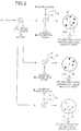
- FIG. 2 is a conceptual diagram of a mechanism of entraining of the absorption liquid by mist generation.
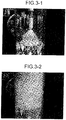
- FIG. 3-1 is a photograph illustrating a state where white smoke is decreased in the CO 2 absorber
- FIG. 3-2 is a photograph illustrating a state where white smoke is generated in the CO 2 absorber.
- SO 3 mist is exemplified as the mist generation material in the description, descriptions with other kinds of mist will be the same.
- the flue gas 12 from the boiler 11 is subjected to a gas purifying treatment such as NO x removal, a reduction in particulates, and SO x removal, and the flue gas 12 is cooled by the cooler 16, resulting in a gas temperature of about 50°C. Since this temperature state is equal to or less than the acid dew point, there is SO 3 mist (for example, 0.1 to 1.0 ⁇ m).
- An SO 3 mist 50 has SO 3 as a nucleus 51 and water vapor 52 that is incorporated into the periphery thereof.
- the absorption liquid is sprayed from nozzles and falls, and the falling absorption liquid and the flue gas are subjected to countercurrent contact such that CO 2 is absorbed by the absorption liquid.
- the flue gas 12 is introduced from the lower side of the CO 2 absorber and is discharged to the upper side.
- the SO 3 mist 50 is not absorbed by the absorption liquid and ascends along with the gas stream of the flue gas 12.
- the absorption liquid when the absorption liquid is supplied from the nozzles, the absorption liquid falls and a part of the absorption liquid and moisture evaporates, and thus a gaseous absorption liquid 41G and water vapor 42 are generated.
- the amount of gaseous absorption liquid 41G and the water vapor 42 further increases as the temperature of the absorption liquid is increased due to, for example, the exothermic reaction of the absorption liquid when CO 2 is absorbed.
- the gaseous absorption liquid 41G and the water vapor 42 are incorporated into the SO 3 mist 50, resulting in a SO 3 mist (bloated nist) 53 including a bloated (for example, about 0.5 to 2.0 ⁇ m) absorption liquid.
- the SO 3 mist 50 in the flue gas 12, before being introduced to the CO 2 recovery equipment 17, incorporates the gaseous absorption liquid 41G and the water vapor 42 in the CO 2 absorber, becomes the SO 3 mist 53 including the absorption liquid, and scatters from the top portion of the CO 2 absorber while being entrained by the flue gas 12. Therefore, the loss of the absorption liquid occurs.
- FIGS. 3-1 and 3-2 The form of white smoke generation in the CO 2 absorber is illustrated in FIGS. 3-1 and 3-2 .
- FIG. 3-1 illustrates a case where the amount of mist generation material is decreased to a predetermined amount or less by providing the mist generation material reduction equipment 20 for the flue gas 12 introduced to the CO 2 absorber and a state where the scatting of the SO 3 mist (bloated mist) 53 including the absorption liquid in the CO 2 absorber is significantly reduced and thus generation of white smoke is suppressed.
- FIG. 3-2 illustrates a case where the flue gas 12 is introduced as it is without providing the mist generation material reduction equipment 20 for the flue gas 12 introduced to the CO 2 absorber and a state where the scatting of the SO 3 mist (bloated mist) 53 including the absorption liquid in the CO 2 absorber occurs and thus white smoke is generated.
- the mist generated in the CO 2 absorber is referred to as the SO 3 mist (bloated mist) 53 including the absorption liquid. Confirming the presence or absence of the generation of bloated mist is referred to as the presence or absence of generation of white smoke, and by suppressing the bloated mist in the CO 2 absorber, generation of white smoke is eliminated. Furthermore, the scattering of the absorption liquid is prevented.
- the gaseous absorption liquid 41G and the gaseous water vapor 42 are separately incorporated into the SO 3 mist 50 in the flue gas 12 in the CO 2 absorber to respectively form a SO 3 mist (bloated mist) 53A including the absorption liquid and a SO 3 mist (bloated mist) 53B including the water vapor.
- mist generation material 53B including the water vapor
- generation of white smoke of the purified gas 18 to be discharged to the outside of a system occurs, a reduction in the mist generation material is also needed.
- mist generation material reduction equipment 20 before introduction to the CO 2 recovery equipment 17, entraining of the CO 2 absorption liquid may be significantly reduced when the flue gas 12 from which CO 2 is reduced is discharged to the outside of the system, and an appropriate air pollution control may be performed.
- the mist generation material reduction equipment 20 that reduces the mist generation material which is the generation source of the mist (the SO 3 mist including the absorption liquid which is the bloated mist) generated in the CO 2 absorber of the CO 2 recovery equipment 17 before introducing the flue gas 12 to the CO 2 recovery equipment 17, the loss of the absorption liquid that scatters to the outside of the system from the CO 2 absorber may be significantly decreased.
- the mist generation material reduction equipment 20 may be provided on the upstream side of the dry type electric dust collector 14, between the dry type electric dust collector 14 and the SO x removal equipment 15, or in either of the front and the rear of the cooler 16, or to be integrated into the cooler 16.
- the amount of SO 3 mist 50 be decreased to 3 ppm or less for prevention of white smoke and prevention of scattering of the absorption liquid in the CO 2 absorber. This is because when the amount of SO 3 mist 50 is decreased to 3 ppm or less, scattering is suppressed, and deterioration of, for example, an amine-based absorption liquid due to SO 3 is prevented.
- the scattering of the absorption liquid is prevented and the deterioration of the absorption liquid is prevented, a decrease in the number of regeneration treatments performed in the regeneration equipment (reclaiming equipment) for the absorption liquid may be achieved, and the loss of the absorption liquid is further significantly decreased, so that a decrease in the amount of the replenished absorption liquid may be achieved. Therefore, the system efficiency of the air pollution control system may be significantly enhanced.
- the electric dust collector is exemplified as the dust reduction equipment in the description.
- the present invention is not limited to this as long as particulates are reduced from the flue gas 12, and besides the electric dust collector, for example, a bag filter or a venturi scrubber may be exemplified.
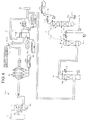
- FIG. 4 is a schematic diagram of the air pollution control system according to the first embodiment.
- FIG. 5 is a schematic diagram of another air pollution control system according to the first embodiment. Note that, in the following embodiment, SO 3 is exemplified as the mist generation material in the description, but the present invention is not limited thereto.
- an air pollution control system 10A includes the NO x removal equipment 13 which reduces nitrogen oxides from the flue gas 12 from the boiler (for example, coal-fired boiler) 11, the electric dust collector 14 which is provided on the downstream side of the NO x removal equipment 13 and reduces particulates from the flue gas 12, the SO x removal equipment 15 which is provided on the downstream side of the electric dust collector 14 and reduces sulfur oxides from the flue gas 12, the cooler 16 which is provided on the downstream side of the SO x removal equipment 15 and has a cooling unit 16a that decreases the gas temperature, and the CO 2 recovery equipment 17 which includes an absorber 17A that brings CO 2 in the flue gas 12 into contact with the absorption liquid so as to be reduced and a regenerator 17B that causes the absorption liquid to emit CO 2 to recover the CO 2 and regenerate the absorption liquid.
- the NO x removal equipment 13 which reduces nitrogen oxides from the flue gas 12 from the boiler (for example, coal-fired boiler) 11
- the electric dust collector 14 which is provided on the downstream side of
- calcium carbonate spraying equipment 31 is provided between the electric dust collector 14 and the SO x removal equipment 15 to spray calcium carbonate (CaCO 3 ) into the flue gas 12.
- a heat exchanger 32 which decreases the flue gas temperature is provided on the upstream side of the SO x removal equipment 15 which is on the downstream side where spraying is performed.
- the calcium carbonate spraying equipment 31 and the heat exchanger 32 according to this embodiment function as the mist generation material reduction equipment 20.
- the flue gas 12 from which particulates are reduced in the electric dust collector 14 is subjected to a reduction in sulfur oxides from the flue gas 12 in the SO x removal equipment 15, the reduced sulfur oxides are supplied with limestone (CaCO 3 ) 15a and oxidation air 15b to become gypsum 15c through a limestone-gypsum method, and desulfurized waste water 15d is separately treated.
- reference numerals 17a, 17b, 17c, 17d, 17e, and 17f denote a reboiler, saturated water vapor, condensed water, a separation drum, recovered CO 2 , and an absorption liquid heat exchanger, respectively.
- the flue gas 12 desulfurized by the SO x removal equipment 15 is cooled by the cooler 16 to cause the flue gas temperature to be 50°C or less, and is introduced to the CO 2 recovery equipment 17 including the absorber 17A and the regenerator 17B.
- CO 2 in the flue gas 12 is reduced by, for example, the amine-based absorption liquid 41.
- a decrease in the amount of the SO 3 mist introduced to the CO 2 recovery equipment 17 is achieved. Therefore, the generation of white smoke of the purified gas 18 discharged from the absorber 17A, which is caused by the mist, is suppressed, and the entraining of the absorption liquid 41 is suppressed.
- the amine-based absorption liquid is exemplified as the absorption liquid.
- the absorption liquid of the present invention is not limited to the amine-based absorption liquid.
- the absorption liquid besides the amine-based absorption liquid, for example, an amino acid-based absorption liquid, an ionic liquid absorption liquid, a hot potassium carbonate absorption liquid made of potassium carbonate and amines, and the like may be exemplified.
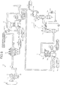
- FIG. 5 is a schematic diagram of an air pollution control system of a modified example of the first embodiment.
- the flue gas 12 is cooled.
- an air pollution control system 10B is provided with a finishing SO x removal unit 16b at the lower portion of the cooler 16 and supplies the limestone (CaCO 3 ) 15a and the oxidation air 15b to form the gypsum 15c through the limestone-gypsum method.
- a strong alkaline agent such as sodium hydroxide (NaOH) may be added along with the limestone.
- a liquid column type is used as a method of supplying a SO x removal absorption liquid.
- the present invention is not limited thereto, and any of sprinkling type, jet type, and filling type may also be used.
- the SO x removal absorption liquid used in the finishing SO x removal unit 16b besides the limestone (CaCO 3 ), a strong alkaline agent such as NaOH, Na 2 CO 3 , NaHCO 3 , Ca(OH) 2 , or Mg(OH) 2 may be exemplified.
- a strong alkaline agent such as NaOH, Na 2 CO 3 , NaHCO 3 , Ca(OH) 2 , or Mg(OH) 2 may be exemplified.
- the strong alkaline agent By using the strong alkaline agent, further enhancement of the SO x removal performance may be achieved, and this is particularly effective in a case where the flue gas 12 having a high sulfur oxide concentration is introduced, thereby decreasing the concentration of sulfur oxides in the flue gas 12 introduced to the CO 2 recovery equipment 17 to an extremely low concentration.
- the SO x removal performance is increased compared to the limestone-gypsum method. Therefore, even in a case where the concentration of sulfur oxides in the introduced flue gas 12 is high,
- the calcium carbonate spraying equipment 31 and the heat exchanger 32 are provided as the mist generation material reduction equipment 20, an air pollution control system in which the absorption liquid 41 is not entrained when the flue gas from which CO 2 is reduced is discharged to the outside may be provided.
- FIG. 6 is a schematic diagram of the air pollution control system according to the second embodiment. Note that, elements that are the same as those of the air pollution control system 10A according to the first embodiment are denoted by the same reference numerals, and overlapping description will not be repeated.
- an air pollution control system 10C includes the NO x removal equipment 13 which reduces nitrogen oxides from the flue gas 12 from the boiler (for example, coal-fired boiler) 11, the electric dust collector 14 which is provided on the downstream side of the NO x removal equipment 13 and reduces particulates from the flue gas 12, the SO x removal equipment 15 which is provided on the downstream side of the electric dust collector 14 and reduces sulfur oxides from the flue gas 12, a heat exchanger which is provided on the upstream side of the SO x removal equipment and decreases the flue gas temperature to an acid dew point or less, the cooler 16 which is provided on the downstream side of the SO x removal equipment 15 and decreases the gas temperature, and the CO 2 recovery equipment 17 which includes the absorber 17A that brings CO 2 in the flue gas 12 into contact with the absorption liquid so as to be reduced and the regenerator 17B that causes the absorption liquid to emit CO 2 to recover CO 2 and regenerate the absorption liquid.
- the heat exchanger 32 is provided to cool the flue gas temperature to the acid dew point or less, thereby converting the mist generation material in the flue gas from the gas state to the condensed state and reducing the mist generation material.
- the heat exchanger 32 not be a general heat exchange member made of steel but be made of a corrosion-resistant material. This is because when SO 3 which is the mist generation material is changed from the gas state to the condensed state (liquid state), resistance to corrosion due to sulfurous acid or sulfuric acid is necessary for long-term stable operation.
- an acid-resistant organic material or inorganic material may be used as the corrosion-resistant material in the present invention.
- organic material such as polytetrafluoroethylene (PTFE) may be exemplified.
- the constituent member of the heat exchanger may be treated by coating with the corrosion-resistant material, and the constituent member itself may be manufactured of a corrosion-resistant material.
- the heat exchanger 32 functions as the mist generation material reduction equipment 20.
- the cooling temperature of the flue gas in the heat exchanger 32 be equal to or lower than the acid dew point.
- the temperature of the flue gas after heat exchange may be cooled to 100 to 60°C.
- the flue gas temperature after heat exchange is 100 to 85°C.
- SO 3 which is the mist generation material may be more actively condensed and reduced.
- the flue gas 12 desulfurized by the SO x removal equipment 15 is cooled by the cooler 16 to cause the flue gas temperature to be 50°C or less, and is introduced to the CO 2 recovery equipment 17 including the absorber 17A and the regenerator 17B.
- CO 2 in the flue gas 12 is reduced by, for example, the amine-based absorption liquid 41.
- a decrease in the amount of the SO 3 mist introduced to the CO 2 recovery equipment 17 is achieved. Therefore, the generation of white smoke of the purified gas 18 discharged from the absorber 17A, which is caused by the mist, is suppressed, and the entraining of the absorption liquid 41 is suppressed.
- alkaline neutralizer spraying equipment which sprays an alkaline neutralizer between the dust reduction equipment and the heat exchanger may be provided, the flue gas 12 may be cooled by the heat exchanger to convert the mist generation material in the flue gas 12 from the gas state to the mist state, and the mist generation material in the mist state may be neutralized by the alkaline neutralizer so as to be reduced.
- the efficiency of reducing the mist-like SO 3 from the flue gas 12 may be enhanced.
- alkaline neutralizer besides calcium carbonate (CaCO 3 ) exemplified in the first embodiment, for example, calcium oxide (CaO), calcium hydroxide (Ca(OH) 2 ), and the like may be exemplified.
- CaO calcium oxide
- Ca(OH) 2 calcium hydroxide
- the heat exchanger 32 having corrosion resistance is provided as the mist generation material reduction equipment 20
- the mist generation material is condensed and reduced. Therefore, an air pollution control system in which the absorption liquid 41 is not entrained when the flue gas from which CO 2 is reduced is discharged from the CO 2 recovery equipment to the outside may be provided.
Applications Claiming Priority (2)
| Application Number | Priority Date | Filing Date | Title |
|---|---|---|---|
| JP2010125393 | 2010-05-31 | ||
| PCT/JP2011/062871 WO2011152551A1 (ja) | 2010-05-31 | 2011-05-31 | 排ガス処理システム及び方法 |
Publications (3)
| Publication Number | Publication Date |
|---|---|
| EP2578298A1 EP2578298A1 (en) | 2013-04-10 |
| EP2578298A4 EP2578298A4 (en) | 2013-12-04 |
| EP2578298B1 true EP2578298B1 (en) | 2020-12-23 |
Family
ID=45066905
Family Applications (1)
| Application Number | Title | Priority Date | Filing Date |
|---|---|---|---|
| EP11789951.8A Active EP2578298B1 (en) | 2010-05-31 | 2011-05-31 | Exhaust gas processing method |
Country Status (6)
| Country | Link |
|---|---|
| US (1) | US8679431B2 (ja) |
| EP (1) | EP2578298B1 (ja) |
| JP (2) | JPWO2011152551A1 (ja) |
| AU (1) | AU2011259878B2 (ja) |
| CA (1) | CA2801159C (ja) |
| WO (1) | WO2011152551A1 (ja) |
Families Citing this family (19)
| Publication number | Priority date | Publication date | Assignee | Title |
|---|---|---|---|---|
| CA2801008C (en) | 2010-05-31 | 2015-12-08 | Mitsubishi Heavy Industries, Ltd. | Air pollution control system and method |
| US8871164B2 (en) | 2010-05-31 | 2014-10-28 | Mitsubushi Heavy Industries, Ltd. | Air pollution control system and method |
| EP2578299B1 (en) | 2010-05-31 | 2020-05-06 | Mitsubishi Heavy Industries Engineering, Ltd. | Exhaust gas treatment method |
| CA2800997C (en) | 2010-05-31 | 2015-12-22 | Mitsubishi Heavy Industries, Ltd. | Air pollution control system and method |
| JP6057545B2 (ja) * | 2012-05-25 | 2017-01-11 | 三菱重工業株式会社 | 排ガス処理装置 |
| CA2886800C (en) * | 2012-10-11 | 2018-04-10 | Mitsubishi Heavy Industries, Ltd. | Air pollution control system and air pollution control method |
| CN103055736A (zh) * | 2012-12-20 | 2013-04-24 | 济南裕兴化工有限责任公司 | 脱硫吸收塔下部浆液搅拌装置 |
| DE102013015280A1 (de) | 2013-09-16 | 2015-03-19 | Rwe Power Aktiengesellschaft | Verfahren und System zur Gaswäsche von aerosolhaltigen Prozessgasen |
| WO2015060795A1 (en) * | 2013-10-21 | 2015-04-30 | Dora Teknolojik Bilgisayar Ürünleri Endüstrisi Anonim Şirketi | Process for the minimization/elimination of so2 and co2 emission emerging from the combustion of coal |
| CN103861440B (zh) * | 2013-12-26 | 2016-01-20 | 张明鑫 | 层烧炉脱硫脱氮烟气处理工艺 |
| US9174165B1 (en) * | 2014-08-28 | 2015-11-03 | Alstom Technology Ltd | Acidic gas removal using dry sorbent injection |
| CN105169917A (zh) * | 2015-09-26 | 2015-12-23 | 国网河南省电力公司电力科学研究院 | 一种基于氨氮摩尔比检测及调控的sncr-scr联合脱硝系统和方法 |
| JP7054581B2 (ja) | 2018-01-30 | 2022-04-14 | 株式会社東芝 | 二酸化炭素回収システムおよび二酸化炭素回収システムの運転方法 |
| CN108479332A (zh) * | 2018-04-16 | 2018-09-04 | 天津华赛尔传热设备有限公司 | 一种低温烟气脱硫脱硝消白系统 |
| CN109569176B (zh) * | 2019-01-23 | 2021-07-16 | 江苏迪思朗环境科技有限公司 | 用于气相白炭黑的环境处理系统 |
| CN110067611A (zh) * | 2019-04-22 | 2019-07-30 | 东南大学 | 一种钙循环法捕集co2联合液氧储能的调峰系统及工作方法 |
| CN111318101A (zh) * | 2020-03-11 | 2020-06-23 | 佛山市蓝颂科技有限公司 | 一种废气处理设备 |
| WO2022014553A1 (ja) * | 2020-07-13 | 2022-01-20 | ナノミストテクノロジーズ株式会社 | 排気ガスの浄化方法と浄化装置 |
| CN112023671A (zh) * | 2020-09-10 | 2020-12-04 | 上海康恒环境股份有限公司 | 一种垃圾焚烧烟气超低排放低温消白系统 |
Family Cites Families (18)
| Publication number | Priority date | Publication date | Assignee | Title |
|---|---|---|---|---|
| JPS5486879A (en) | 1977-12-23 | 1979-07-10 | Sanki Eng Co Ltd | Wet type electric dust collector with harmful gas remover |
| JPH0779950B2 (ja) | 1989-12-25 | 1995-08-30 | 三菱重工業株式会社 | 燃焼排ガス中のco▲下2▼の除去方法 |
| DE4133581A1 (de) | 1991-10-10 | 1993-04-15 | Ver Kunststoffwerke Gmbh | Verfahren und vorrichtung zum reinigen von abgasen |
| JP3504674B2 (ja) | 1992-03-03 | 2004-03-08 | 関西電力株式会社 | 燃焼排ガス中の二酸化炭素と硫黄酸化物を除去する方法 |
| JP3486220B2 (ja) * | 1994-03-08 | 2004-01-13 | バブコック日立株式会社 | 燃焼排ガス浄化方法および装置 |
| JP3621822B2 (ja) * | 1997-03-03 | 2005-02-16 | 三菱重工業株式会社 | 排煙処理方法及び設備 |
| JP2001347186A (ja) * | 2000-06-09 | 2001-12-18 | Ishikawajima Harima Heavy Ind Co Ltd | 排煙除塵装置 |
| JP4216152B2 (ja) * | 2003-09-16 | 2009-01-28 | 関西電力株式会社 | 脱硫脱炭酸方法及びその装置 |
| JP4920993B2 (ja) | 2005-04-26 | 2012-04-18 | 三菱重工メカトロシステムズ株式会社 | 排ガス処理装置および排ガス処理方法 |
| CA2672577C (en) * | 2006-12-27 | 2014-08-05 | Babcock-Hitachi Kabushiki Kaisha | Exhaust gas treating method and apparatus |
| CA2672580C (en) | 2006-12-27 | 2015-02-03 | Babcock-Hitachi Kabushiki Kaisha | Exhaust gas treating method and apparatus |
| JP4318055B2 (ja) * | 2007-01-15 | 2009-08-19 | 株式会社日立プラントテクノロジー | 硫黄酸化物を含む排ガスの処理方法およびその装置 |
| JP2008200561A (ja) * | 2007-02-16 | 2008-09-04 | Hitachi Plant Technologies Ltd | 硫黄酸化物を含む排ガスの処理方法 |
| JP5384799B2 (ja) * | 2007-03-30 | 2014-01-08 | 三菱重工メカトロシステムズ株式会社 | 排ガス処理装置および排ガス処理方法 |
| JP5093205B2 (ja) * | 2009-09-30 | 2012-12-12 | 株式会社日立製作所 | 二酸化炭素回収型発電システム |
| CA2801008C (en) * | 2010-05-31 | 2015-12-08 | Mitsubishi Heavy Industries, Ltd. | Air pollution control system and method |
| US8871164B2 (en) | 2010-05-31 | 2014-10-28 | Mitsubushi Heavy Industries, Ltd. | Air pollution control system and method |
| US8025860B1 (en) | 2010-07-08 | 2011-09-27 | Air Products And Chemicals, Inc. | Removal of acid mists |
-
2011
- 2011-05-31 WO PCT/JP2011/062871 patent/WO2011152551A1/ja active Application Filing
- 2011-05-31 EP EP11789951.8A patent/EP2578298B1/en active Active
- 2011-05-31 AU AU2011259878A patent/AU2011259878B2/en active Active
- 2011-05-31 JP JP2012518481A patent/JPWO2011152551A1/ja active Pending
- 2011-05-31 US US13/700,924 patent/US8679431B2/en active Active
- 2011-05-31 CA CA2801159A patent/CA2801159C/en active Active
-
2015
- 2015-06-30 JP JP2015132030A patent/JP6045654B2/ja active Active
Non-Patent Citations (1)
| Title |
|---|
| None * |
Also Published As
| Publication number | Publication date |
|---|---|
| JPWO2011152551A1 (ja) | 2013-08-01 |
| JP6045654B2 (ja) | 2016-12-14 |
| EP2578298A4 (en) | 2013-12-04 |
| CA2801159C (en) | 2015-12-01 |
| WO2011152551A1 (ja) | 2011-12-08 |
| JP2015211969A (ja) | 2015-11-26 |
| AU2011259878B2 (en) | 2015-01-15 |
| US20130156673A1 (en) | 2013-06-20 |
| EP2578298A1 (en) | 2013-04-10 |
| AU2011259878A1 (en) | 2012-12-20 |
| US8679431B2 (en) | 2014-03-25 |
| CA2801159A1 (en) | 2011-12-08 |
Similar Documents
| Publication | Publication Date | Title |
|---|---|---|
| EP2578298B1 (en) | Exhaust gas processing method | |
| EP2578299B1 (en) | Exhaust gas treatment method | |
| EP2578295B1 (en) | Exhaust gas treatment system and method | |
| CA2801291C (en) | Air pollution control system and method | |
| AU2011259876B2 (en) | Exhaust gas treatment system and method | |
| CA2800994C (en) | Air pollution control system and method | |
| EP2578294B1 (en) | Exhaust gas treatment method |
Legal Events
| Date | Code | Title | Description |
|---|---|---|---|
| PUAI | Public reference made under article 153(3) epc to a published international application that has entered the european phase |
Free format text: ORIGINAL CODE: 0009012 |
|
| 17P | Request for examination filed |
Effective date: 20121128 |
|
| AK | Designated contracting states |
Kind code of ref document: A1 Designated state(s): AL AT BE BG CH CY CZ DE DK EE ES FI FR GB GR HR HU IE IS IT LI LT LU LV MC MK MT NL NO PL PT RO RS SE SI SK SM TR |
|
| DAX | Request for extension of the european patent (deleted) | ||
| A4 | Supplementary search report drawn up and despatched |
Effective date: 20131107 |
|
| RIC1 | Information provided on ipc code assigned before grant |
Ipc: B03C 3/017 20060101ALI20131031BHEP Ipc: B01D 53/62 20060101AFI20131031BHEP Ipc: B01D 53/75 20060101ALI20131031BHEP Ipc: B01D 53/50 20060101ALI20131031BHEP |
|
| RAP1 | Party data changed (applicant data changed or rights of an application transferred) |
Owner name: MITSUBISHI HEAVY INDUSTRIES ENGINEERING, LTD. |
|
| STAA | Information on the status of an ep patent application or granted ep patent |
Free format text: STATUS: EXAMINATION IS IN PROGRESS |
|
| 17Q | First examination report despatched |
Effective date: 20181128 |
|
| GRAP | Despatch of communication of intention to grant a patent |
Free format text: ORIGINAL CODE: EPIDOSNIGR1 |
|
| STAA | Information on the status of an ep patent application or granted ep patent |
Free format text: STATUS: GRANT OF PATENT IS INTENDED |
|
| INTG | Intention to grant announced |
Effective date: 20200917 |
|
| GRAS | Grant fee paid |
Free format text: ORIGINAL CODE: EPIDOSNIGR3 |
|
| GRAA | (expected) grant |
Free format text: ORIGINAL CODE: 0009210 |
|
| STAA | Information on the status of an ep patent application or granted ep patent |
Free format text: STATUS: THE PATENT HAS BEEN GRANTED |
|
| AK | Designated contracting states |
Kind code of ref document: B1 Designated state(s): AL AT BE BG CH CY CZ DE DK EE ES FI FR GB GR HR HU IE IS IT LI LT LU LV MC MK MT NL NO PL PT RO RS SE SI SK SM TR |
|
| REG | Reference to a national code |
Ref country code: GB Ref legal event code: FG4D |
|
| REG | Reference to a national code |
Ref country code: DE Ref legal event code: R096 Ref document number: 602011069750 Country of ref document: DE |
|
| REG | Reference to a national code |
Ref country code: AT Ref legal event code: REF Ref document number: 1347181 Country of ref document: AT Kind code of ref document: T Effective date: 20210115 |
|
| REG | Reference to a national code |
Ref country code: IE Ref legal event code: FG4D |
|
| REG | Reference to a national code |
Ref country code: NL Ref legal event code: FP |
|
| REG | Reference to a national code |
Ref country code: NO Ref legal event code: T2 Effective date: 20201223 |
|
| PG25 | Lapsed in a contracting state [announced via postgrant information from national office to epo] |
Ref country code: RS Free format text: LAPSE BECAUSE OF FAILURE TO SUBMIT A TRANSLATION OF THE DESCRIPTION OR TO PAY THE FEE WITHIN THE PRESCRIBED TIME-LIMIT Effective date: 20201223 Ref country code: FI Free format text: LAPSE BECAUSE OF FAILURE TO SUBMIT A TRANSLATION OF THE DESCRIPTION OR TO PAY THE FEE WITHIN THE PRESCRIBED TIME-LIMIT Effective date: 20201223 Ref country code: GR Free format text: LAPSE BECAUSE OF FAILURE TO SUBMIT A TRANSLATION OF THE DESCRIPTION OR TO PAY THE FEE WITHIN THE PRESCRIBED TIME-LIMIT Effective date: 20210324 |
|
| REG | Reference to a national code |
Ref country code: AT Ref legal event code: MK05 Ref document number: 1347181 Country of ref document: AT Kind code of ref document: T Effective date: 20201223 |
|
| PG25 | Lapsed in a contracting state [announced via postgrant information from national office to epo] |
Ref country code: SE Free format text: LAPSE BECAUSE OF FAILURE TO SUBMIT A TRANSLATION OF THE DESCRIPTION OR TO PAY THE FEE WITHIN THE PRESCRIBED TIME-LIMIT Effective date: 20201223 Ref country code: LV Free format text: LAPSE BECAUSE OF FAILURE TO SUBMIT A TRANSLATION OF THE DESCRIPTION OR TO PAY THE FEE WITHIN THE PRESCRIBED TIME-LIMIT Effective date: 20201223 Ref country code: BG Free format text: LAPSE BECAUSE OF FAILURE TO SUBMIT A TRANSLATION OF THE DESCRIPTION OR TO PAY THE FEE WITHIN THE PRESCRIBED TIME-LIMIT Effective date: 20210323 |
|
| PG25 | Lapsed in a contracting state [announced via postgrant information from national office to epo] |
Ref country code: HR Free format text: LAPSE BECAUSE OF FAILURE TO SUBMIT A TRANSLATION OF THE DESCRIPTION OR TO PAY THE FEE WITHIN THE PRESCRIBED TIME-LIMIT Effective date: 20201223 |
|
| REG | Reference to a national code |
Ref country code: LT Ref legal event code: MG9D |
|
| PG25 | Lapsed in a contracting state [announced via postgrant information from national office to epo] |
Ref country code: SK Free format text: LAPSE BECAUSE OF FAILURE TO SUBMIT A TRANSLATION OF THE DESCRIPTION OR TO PAY THE FEE WITHIN THE PRESCRIBED TIME-LIMIT Effective date: 20201223 Ref country code: RO Free format text: LAPSE BECAUSE OF FAILURE TO SUBMIT A TRANSLATION OF THE DESCRIPTION OR TO PAY THE FEE WITHIN THE PRESCRIBED TIME-LIMIT Effective date: 20201223 Ref country code: PT Free format text: LAPSE BECAUSE OF FAILURE TO SUBMIT A TRANSLATION OF THE DESCRIPTION OR TO PAY THE FEE WITHIN THE PRESCRIBED TIME-LIMIT Effective date: 20210423 Ref country code: LT Free format text: LAPSE BECAUSE OF FAILURE TO SUBMIT A TRANSLATION OF THE DESCRIPTION OR TO PAY THE FEE WITHIN THE PRESCRIBED TIME-LIMIT Effective date: 20201223 Ref country code: EE Free format text: LAPSE BECAUSE OF FAILURE TO SUBMIT A TRANSLATION OF THE DESCRIPTION OR TO PAY THE FEE WITHIN THE PRESCRIBED TIME-LIMIT Effective date: 20201223 Ref country code: CZ Free format text: LAPSE BECAUSE OF FAILURE TO SUBMIT A TRANSLATION OF THE DESCRIPTION OR TO PAY THE FEE WITHIN THE PRESCRIBED TIME-LIMIT Effective date: 20201223 Ref country code: SM Free format text: LAPSE BECAUSE OF FAILURE TO SUBMIT A TRANSLATION OF THE DESCRIPTION OR TO PAY THE FEE WITHIN THE PRESCRIBED TIME-LIMIT Effective date: 20201223 |
|
| PG25 | Lapsed in a contracting state [announced via postgrant information from national office to epo] |
Ref country code: AT Free format text: LAPSE BECAUSE OF FAILURE TO SUBMIT A TRANSLATION OF THE DESCRIPTION OR TO PAY THE FEE WITHIN THE PRESCRIBED TIME-LIMIT Effective date: 20201223 Ref country code: PL Free format text: LAPSE BECAUSE OF FAILURE TO SUBMIT A TRANSLATION OF THE DESCRIPTION OR TO PAY THE FEE WITHIN THE PRESCRIBED TIME-LIMIT Effective date: 20201223 |
|
| REG | Reference to a national code |
Ref country code: DE Ref legal event code: R097 Ref document number: 602011069750 Country of ref document: DE |
|
| PG25 | Lapsed in a contracting state [announced via postgrant information from national office to epo] |
Ref country code: IS Free format text: LAPSE BECAUSE OF FAILURE TO SUBMIT A TRANSLATION OF THE DESCRIPTION OR TO PAY THE FEE WITHIN THE PRESCRIBED TIME-LIMIT Effective date: 20210423 |
|
| PG25 | Lapsed in a contracting state [announced via postgrant information from national office to epo] |
Ref country code: AL Free format text: LAPSE BECAUSE OF FAILURE TO SUBMIT A TRANSLATION OF THE DESCRIPTION OR TO PAY THE FEE WITHIN THE PRESCRIBED TIME-LIMIT Effective date: 20201223 Ref country code: IT Free format text: LAPSE BECAUSE OF FAILURE TO SUBMIT A TRANSLATION OF THE DESCRIPTION OR TO PAY THE FEE WITHIN THE PRESCRIBED TIME-LIMIT Effective date: 20201223 |
|
| PLBE | No opposition filed within time limit |
Free format text: ORIGINAL CODE: 0009261 |
|
| STAA | Information on the status of an ep patent application or granted ep patent |
Free format text: STATUS: NO OPPOSITION FILED WITHIN TIME LIMIT |
|
| PG25 | Lapsed in a contracting state [announced via postgrant information from national office to epo] |
Ref country code: ES Free format text: LAPSE BECAUSE OF FAILURE TO SUBMIT A TRANSLATION OF THE DESCRIPTION OR TO PAY THE FEE WITHIN THE PRESCRIBED TIME-LIMIT Effective date: 20201223 Ref country code: DK Free format text: LAPSE BECAUSE OF FAILURE TO SUBMIT A TRANSLATION OF THE DESCRIPTION OR TO PAY THE FEE WITHIN THE PRESCRIBED TIME-LIMIT Effective date: 20201223 |
|
| 26N | No opposition filed |
Effective date: 20210924 |
|
| REG | Reference to a national code |
Ref country code: CH Ref legal event code: PL |
|
| PG25 | Lapsed in a contracting state [announced via postgrant information from national office to epo] |
Ref country code: CH Free format text: LAPSE BECAUSE OF NON-PAYMENT OF DUE FEES Effective date: 20210531 Ref country code: MC Free format text: LAPSE BECAUSE OF FAILURE TO SUBMIT A TRANSLATION OF THE DESCRIPTION OR TO PAY THE FEE WITHIN THE PRESCRIBED TIME-LIMIT Effective date: 20201223 Ref country code: LI Free format text: LAPSE BECAUSE OF NON-PAYMENT OF DUE FEES Effective date: 20210531 Ref country code: LU Free format text: LAPSE BECAUSE OF NON-PAYMENT OF DUE FEES Effective date: 20210531 |
|
| PG25 | Lapsed in a contracting state [announced via postgrant information from national office to epo] |
Ref country code: SI Free format text: LAPSE BECAUSE OF FAILURE TO SUBMIT A TRANSLATION OF THE DESCRIPTION OR TO PAY THE FEE WITHIN THE PRESCRIBED TIME-LIMIT Effective date: 20201223 |
|
| PG25 | Lapsed in a contracting state [announced via postgrant information from national office to epo] |
Ref country code: IE Free format text: LAPSE BECAUSE OF NON-PAYMENT OF DUE FEES Effective date: 20210531 |
|
| PG25 | Lapsed in a contracting state [announced via postgrant information from national office to epo] |
Ref country code: IS Free format text: LAPSE BECAUSE OF FAILURE TO SUBMIT A TRANSLATION OF THE DESCRIPTION OR TO PAY THE FEE WITHIN THE PRESCRIBED TIME-LIMIT Effective date: 20210423 |
|
| REG | Reference to a national code |
Ref country code: DE Ref legal event code: R082 Ref document number: 602011069750 Country of ref document: DE Representative=s name: CBDL PATENTANWAELTE GBR, DE |
|
| REG | Reference to a national code |
Ref country code: FR Ref legal event code: PLFP Year of fee payment: 13 |
|
| PG25 | Lapsed in a contracting state [announced via postgrant information from national office to epo] |
Ref country code: HU Free format text: LAPSE BECAUSE OF FAILURE TO SUBMIT A TRANSLATION OF THE DESCRIPTION OR TO PAY THE FEE WITHIN THE PRESCRIBED TIME-LIMIT; INVALID AB INITIO Effective date: 20110531 Ref country code: CY Free format text: LAPSE BECAUSE OF FAILURE TO SUBMIT A TRANSLATION OF THE DESCRIPTION OR TO PAY THE FEE WITHIN THE PRESCRIBED TIME-LIMIT Effective date: 20201223 |
|
| P01 | Opt-out of the competence of the unified patent court (upc) registered |
Effective date: 20230522 |
|
| PGFP | Annual fee paid to national office [announced via postgrant information from national office to epo] |
Ref country code: NL Payment date: 20230417 Year of fee payment: 13 |
|
| PGFP | Annual fee paid to national office [announced via postgrant information from national office to epo] |
Ref country code: NO Payment date: 20230510 Year of fee payment: 13 Ref country code: FR Payment date: 20230411 Year of fee payment: 13 Ref country code: DE Payment date: 20230404 Year of fee payment: 13 |
|
| REG | Reference to a national code |
Ref country code: DE Ref legal event code: R081 Ref document number: 602011069750 Country of ref document: DE Owner name: MITSUBISHI HEAVY INDUSTRIES, LTD., JP Free format text: FORMER OWNER: MITSUBISHI HEAVY INDUSTRIES ENGINEERING, LTD., YOKOHAMA-SHI, KANAGAWA, JP |
|
| PGFP | Annual fee paid to national office [announced via postgrant information from national office to epo] |
Ref country code: BE Payment date: 20230418 Year of fee payment: 13 |
|
| PGFP | Annual fee paid to national office [announced via postgrant information from national office to epo] |
Ref country code: GB Payment date: 20230406 Year of fee payment: 13 |
|
| REG | Reference to a national code |
Ref country code: NL Ref legal event code: PD Owner name: MITSUBISHI HEAVY INDUSTRIES, LTD.; JP Free format text: DETAILS ASSIGNMENT: CHANGE OF OWNER(S), ASSIGNMENT; FORMER OWNER NAME: MHI ENGINEERING, LTD. Effective date: 20231206 Ref country code: NL Ref legal event code: HC Owner name: MHI ENGINEERING, LTD.; JP Free format text: DETAILS ASSIGNMENT: CHANGE OF OWNER(S), CHANGE OF OWNER(S) NAME; FORMER OWNER NAME: MITSUBISHI HEAVY INDUSTRIES ENGINEERING, LTD. Effective date: 20231206 |
|
| REG | Reference to a national code |
Ref country code: BE Ref legal event code: PD Owner name: MITSUBISHI HEAVY INDUSTRIES, LTD.; JP Free format text: DETAILS ASSIGNMENT: CHANGE OF OWNER(S), ASSIGNMENT; FORMER OWNER NAME: MHI ENGINEERING, LTD. Effective date: 20231208 Ref country code: BE Ref legal event code: HC Owner name: MHI ENGINEERING, LTD.; JP Free format text: DETAILS ASSIGNMENT: CHANGE OF OWNER(S), CHANGE OF OWNER(S) NAME; FORMER OWNER NAME: MITSUBISHI HEAVY INDUSTRIES ENGINEERING, LTD. Effective date: 20231208 |