EP2577343B1 - Determining spatial orientation and angular rate of change of orientation information of a body from multiple electromagnetic signals - Google Patents
Determining spatial orientation and angular rate of change of orientation information of a body from multiple electromagnetic signals Download PDFInfo
- Publication number
- EP2577343B1 EP2577343B1 EP11723151.4A EP11723151A EP2577343B1 EP 2577343 B1 EP2577343 B1 EP 2577343B1 EP 11723151 A EP11723151 A EP 11723151A EP 2577343 B1 EP2577343 B1 EP 2577343B1
- Authority
- EP
- European Patent Office
- Prior art keywords
- body frame
- angle
- frame
- received
- rate
- Prior art date
- Legal status (The legal status is an assumption and is not a legal conclusion. Google has not performed a legal analysis and makes no representation as to the accuracy of the status listed.)
- Active
Links
Images


Classifications
-
- G—PHYSICS
- G01—MEASURING; TESTING
- G01C—MEASURING DISTANCES, LEVELS OR BEARINGS; SURVEYING; NAVIGATION; GYROSCOPIC INSTRUMENTS; PHOTOGRAMMETRY OR VIDEOGRAMMETRY
- G01C21/00—Navigation; Navigational instruments not provided for in groups G01C1/00 - G01C19/00
- G01C21/20—Instruments for performing navigational calculations
-
- G—PHYSICS
- G01—MEASURING; TESTING
- G01S—RADIO DIRECTION-FINDING; RADIO NAVIGATION; DETERMINING DISTANCE OR VELOCITY BY USE OF RADIO WAVES; LOCATING OR PRESENCE-DETECTING BY USE OF THE REFLECTION OR RERADIATION OF RADIO WAVES; ANALOGOUS ARRANGEMENTS USING OTHER WAVES
- G01S19/00—Satellite radio beacon positioning systems; Determining position, velocity or attitude using signals transmitted by such systems
- G01S19/38—Determining a navigation solution using signals transmitted by a satellite radio beacon positioning system
- G01S19/39—Determining a navigation solution using signals transmitted by a satellite radio beacon positioning system the satellite radio beacon positioning system transmitting time-stamped messages, e.g. GPS [Global Positioning System], GLONASS [Global Orbiting Navigation Satellite System] or GALILEO
- G01S19/40—Correcting position, velocity or attitude
-
- G—PHYSICS
- G01—MEASURING; TESTING
- G01S—RADIO DIRECTION-FINDING; RADIO NAVIGATION; DETERMINING DISTANCE OR VELOCITY BY USE OF RADIO WAVES; LOCATING OR PRESENCE-DETECTING BY USE OF THE REFLECTION OR RERADIATION OF RADIO WAVES; ANALOGOUS ARRANGEMENTS USING OTHER WAVES
- G01S19/00—Satellite radio beacon positioning systems; Determining position, velocity or attitude using signals transmitted by such systems
- G01S19/01—Satellite radio beacon positioning systems transmitting time-stamped messages, e.g. GPS [Global Positioning System], GLONASS [Global Orbiting Navigation Satellite System] or GALILEO
- G01S19/13—Receivers
- G01S19/35—Constructional details or hardware or software details of the signal processing chain
- G01S19/36—Constructional details or hardware or software details of the signal processing chain relating to the receiver frond end
-
- G—PHYSICS
- G01—MEASURING; TESTING
- G01C—MEASURING DISTANCES, LEVELS OR BEARINGS; SURVEYING; NAVIGATION; GYROSCOPIC INSTRUMENTS; PHOTOGRAMMETRY OR VIDEOGRAMMETRY
- G01C21/00—Navigation; Navigational instruments not provided for in groups G01C1/00 - G01C19/00
- G01C21/10—Navigation; Navigational instruments not provided for in groups G01C1/00 - G01C19/00 by using measurements of speed or acceleration
-
- G—PHYSICS
- G01—MEASURING; TESTING
- G01S—RADIO DIRECTION-FINDING; RADIO NAVIGATION; DETERMINING DISTANCE OR VELOCITY BY USE OF RADIO WAVES; LOCATING OR PRESENCE-DETECTING BY USE OF THE REFLECTION OR RERADIATION OF RADIO WAVES; ANALOGOUS ARRANGEMENTS USING OTHER WAVES
- G01S19/00—Satellite radio beacon positioning systems; Determining position, velocity or attitude using signals transmitted by such systems
- G01S19/01—Satellite radio beacon positioning systems transmitting time-stamped messages, e.g. GPS [Global Positioning System], GLONASS [Global Orbiting Navigation Satellite System] or GALILEO
- G01S19/13—Receivers
- G01S19/24—Acquisition or tracking or demodulation of signals transmitted by the system
- G01S19/26—Acquisition or tracking or demodulation of signals transmitted by the system involving a sensor measurement for aiding acquisition or tracking
-
- G—PHYSICS
- G01—MEASURING; TESTING
- G01S—RADIO DIRECTION-FINDING; RADIO NAVIGATION; DETERMINING DISTANCE OR VELOCITY BY USE OF RADIO WAVES; LOCATING OR PRESENCE-DETECTING BY USE OF THE REFLECTION OR RERADIATION OF RADIO WAVES; ANALOGOUS ARRANGEMENTS USING OTHER WAVES
- G01S19/00—Satellite radio beacon positioning systems; Determining position, velocity or attitude using signals transmitted by such systems
- G01S19/01—Satellite radio beacon positioning systems transmitting time-stamped messages, e.g. GPS [Global Positioning System], GLONASS [Global Orbiting Navigation Satellite System] or GALILEO
- G01S19/13—Receivers
- G01S19/31—Acquisition or tracking of other signals for positioning
-
- G—PHYSICS
- G01—MEASURING; TESTING
- G01S—RADIO DIRECTION-FINDING; RADIO NAVIGATION; DETERMINING DISTANCE OR VELOCITY BY USE OF RADIO WAVES; LOCATING OR PRESENCE-DETECTING BY USE OF THE REFLECTION OR RERADIATION OF RADIO WAVES; ANALOGOUS ARRANGEMENTS USING OTHER WAVES
- G01S19/00—Satellite radio beacon positioning systems; Determining position, velocity or attitude using signals transmitted by such systems
- G01S19/38—Determining a navigation solution using signals transmitted by a satellite radio beacon positioning system
- G01S19/39—Determining a navigation solution using signals transmitted by a satellite radio beacon positioning system the satellite radio beacon positioning system transmitting time-stamped messages, e.g. GPS [Global Positioning System], GLONASS [Global Orbiting Navigation Satellite System] or GALILEO
- G01S19/42—Determining position
-
- G—PHYSICS
- G01—MEASURING; TESTING
- G01S—RADIO DIRECTION-FINDING; RADIO NAVIGATION; DETERMINING DISTANCE OR VELOCITY BY USE OF RADIO WAVES; LOCATING OR PRESENCE-DETECTING BY USE OF THE REFLECTION OR RERADIATION OF RADIO WAVES; ANALOGOUS ARRANGEMENTS USING OTHER WAVES
- G01S19/00—Satellite radio beacon positioning systems; Determining position, velocity or attitude using signals transmitted by such systems
- G01S19/38—Determining a navigation solution using signals transmitted by a satellite radio beacon positioning system
- G01S19/39—Determining a navigation solution using signals transmitted by a satellite radio beacon positioning system the satellite radio beacon positioning system transmitting time-stamped messages, e.g. GPS [Global Positioning System], GLONASS [Global Orbiting Navigation Satellite System] or GALILEO
- G01S19/53—Determining attitude
-
- G—PHYSICS
- G01—MEASURING; TESTING
- G01S—RADIO DIRECTION-FINDING; RADIO NAVIGATION; DETERMINING DISTANCE OR VELOCITY BY USE OF RADIO WAVES; LOCATING OR PRESENCE-DETECTING BY USE OF THE REFLECTION OR RERADIATION OF RADIO WAVES; ANALOGOUS ARRANGEMENTS USING OTHER WAVES
- G01S19/00—Satellite radio beacon positioning systems; Determining position, velocity or attitude using signals transmitted by such systems
- G01S19/01—Satellite radio beacon positioning systems transmitting time-stamped messages, e.g. GPS [Global Positioning System], GLONASS [Global Orbiting Navigation Satellite System] or GALILEO
- G01S19/13—Receivers
- G01S19/14—Receivers specially adapted for specific applications
- G01S19/18—Military applications
-
- G—PHYSICS
- G01—MEASURING; TESTING
- G01S—RADIO DIRECTION-FINDING; RADIO NAVIGATION; DETERMINING DISTANCE OR VELOCITY BY USE OF RADIO WAVES; LOCATING OR PRESENCE-DETECTING BY USE OF THE REFLECTION OR RERADIATION OF RADIO WAVES; ANALOGOUS ARRANGEMENTS USING OTHER WAVES
- G01S3/00—Direction-finders for determining the direction from which infrasonic, sonic, ultrasonic, or electromagnetic waves, or particle emission, not having a directional significance, are being received
- G01S3/02—Direction-finders for determining the direction from which infrasonic, sonic, ultrasonic, or electromagnetic waves, or particle emission, not having a directional significance, are being received using radio waves
- G01S3/14—Systems for determining direction or deviation from predetermined direction
- G01S3/52—Systems for determining direction or deviation from predetermined direction using a receiving antenna moving, or appearing to move, in a cyclic path to produce a Doppler variation of frequency of the received signal
Definitions
- This specification relates to determining spatial orientation information (for example, the orientation and/or rate of change in the orientation) of a body based upon multiple electromagnetic signals received at the body from different transmitters of a navigational system, and the use of spatial orientation information in navigation of the body.
- spatial orientation information for example, the orientation and/or rate of change in the orientation
- Determining the spatial orientation, and/or its rate of change, for a body is useful in numerous different applications.
- an airborne body such as an airplane or a helicopter
- the spatial orientation of the airborne body may be used in the navigation of the body from its current location to a desired location or in a desired direction.
- the spatial orientation information (including the orientation and its rate of change) may be provided to a person who may use the information to pilot the airborne body manually, or may be provided to a computer-controlled navigation system that controls the navigation of the airborne body.
- Another application in which the spatial orientation of a body is useful is in underground applications such as underground drilling for oil, natural gas and the like.
- orientation information for an underground drill head that cannot be directly observed by sight may be useful or even necessary in navigating the drill in an intended direction or to an intended target location. It should be understood that these two general examples of applications in which spatial orientation information may useful are intended to be illustrative, and that there are many other present and future applications in which spatial orientation information may similarly be useful.
- pitch angle describes an upward or downward rotation of the nose of the aircraft
- roll angle describes a rotation about the body of the aircraft (or in other words, tilting upward or downward of the wings)
- yaw angle describes the angle of side rotation (or in other words, the nose of the aircraft moving to the right or the left).
- On-board navigation systems such as these traditional types may also provide information as to the rate of change in the aircraft's attitude. While in many applications, such on-board navigational systems are entirely sufficient, in many applications they may not be sufficiently accurate or responsive, by themselves. For example, one issue that may be present with inertial navigation systems is possible drift in its spatial orientation determinations over time, and as such there may be a need to periodically calibrate or correct for such drift. In addition, the rate of change in the spatial orientation may be so dramatic or rapid for a particular body that such spatial orientation determination mechanisms are simply ineffective by themselves.
- GNSS global navigation satellite system
- GPS Global Positioning System
- GLONASS Global Navigation Satellite System
- a common and primary use that is made of received GNSS transmissions is to determine the current position of the body. This is known quite ubiquitously, as being used by aircraft and automobiles for example.
- a body receives transmissions from at least four different satellites of the GNSS, and uses those transmissions to determine the current position of the body.
- One method for determining the three-dimensional position (longitude, latitude, and altitude) of a body includes receiving electromagnetic signals transmitted by satellites or beacons positioned at known locations. Small electric receivers can be used to calculate position based upon these received electromagnetic signals.
- the transmissions of GNSS satellites typically include time-stamp information as to when the transmission was sent by the satellite, so that the receiving body is able to use a time of receipt to calculate the body's distance from the particular satellite.
- the transmissions of GNSS satellites also conventionally include the current position of the orbiting GNSS satellite, or more specifically, ephemeris data that describes the orbital information for the satellite.
- the body is provided with information regarding the current position of each of the satellites whose transmissions it has received, and uses that information, plus the distance each satellite is away from the body, to determine the position of the body.
- GNSS's have also been used more recently to determine spatial orientation information for a body.
- a body has been equipped with a receiving and directional antenna system that is capable of detecting a precise direction, defined by a vector, from which the electromagnetic transmission was received.
- the receiving system with the directional antenna system in such systems is configured to detect a vector direction for the received GNSS transmission that is defined by two angles, namely, an azimuth angle and an elevation angle. Knowing the precise receipt vector for each of the GNSS transmissions enables spatial orientation information to be determined in these bodies.
- a processing system is able to calculate spatial orientation information for the body, including for example conventionally defined yaw, pitch and roll components.
- receiving and directional antenna systems that are capable of detecting both an azimuth angle and an elevation angle are generally complex and impose space requirements aboard bodies whose orientation is being determined, as compared for example to simpler receiving and antenna systems.
- Certain antenna configurations can also be used as rotation sensors to make measurements that determine the orientation of the body without the aid of motion or additional sensors.
- Such systems use the GNSS signals arriving at antennas on the body to determine the direction toward the GNSS satellites relative to the body orientation.
- Geometry implies that the direction from the body toward a single satellite can be described by specifying the three angles formed between the satellite and the three body axes. The cosines of these angles are used to specify a unique direction cosine vector for each satellite expressed in the coordinate system for a given frame.
- Traditional systems that use GNSS for attitude estimation will take measurements of the direction cosine vectors made in the body frame and compare these measurements to satellite positions known in the navigation frame.
- angle-off-bore-sight can also be described as an "elevation" angle for the satellite relative to the plane defined by the body y and z axes. Given that the elevation angle has been measured, then the satellite direction cosine vector can be determined by measuring an additional "azimuth" angle that specifies how the satellite direction is rotated around the x-axis.
- Traditional systems determine the body orientation relative to the navigation frame by measuring the vector directions (i.e., both the elevation and the azimuth angles) toward at least two satellites, and using these body measurements and the known direction of the satellites in the navigation frame to derive the actual rotation of the body frame relative to the navigation frame.
- US 6 452 543 B1 discloses a null slit antenna pattern that receives GPS signals from at least three GPS satellites functioning as pseudo stars for spin rate and spin axis attitude determination of a spinning space vehicle in an earth orbit below the GPS satellites.
- systems, components and methods are provided that enable spatial orientation information to be determined for a body without requiring that the direction from which a navigating transmission from an external navigational system transmitter is received be detected with the degree of precision required in prior systems.
- the systems, components and methods described in this specification are able to use less precise directional information and still adequately and effectively determine spatial orientation information for the body.
- the systems, components and methods described in this specification enable the use of, although do not require, receiving and directional antenna systems that may be less complex and/or that may impose less space requirements within or on the body than has been the case in prior systems.
- the invention is defined by the claims appended.
- one innovative aspect of the subject matter described in this specification can be embodied in methods that include the actions of receiving, by receiving equipment located with the body, at least three sets of electromagnetic signals, each of the received sets of electromagnetic signals having been transmitted by a different one of at least three separate transmitters at different locations; detecting, for each one of the received sets of electromagnetic signals, partial directional information that partially defines a direction from the body to the transmitting transmitter from which the set of electromagnetic signals was received, the detected partial directional information including a first one angle of two angles that fully define an arrival direction from which the body received the set of electromagnetic signals in relation to a body frame, the detected partial directional information not including a second one of the two angles that fully define the arrival direction; and determining the spatial orientation of the body, including yaw, pitch, and roll angles relative to a navigation frame, using the detected partial directional information for each one of the received sets of electromagnetic signals.
- the method further includes detecting, for each one of the received sets of electromagnetic signals, a rate of change of partial directional information, the detected rate of change of partial directional information including a rate of change of the first one angle of two angles that fully define the arrival direction from which the body received the electromagnetic signal set in relation to the body frame; and determining an angular rate of change of the spatial orientation of the body frame with respect to the navigation frame, where the determining includes using the detected rate of change of partial directional for each one of the received sets of electromagnetic signals and the determined spatial orientation.
- Other embodiments of this aspect include corresponding systems, apparatus, and computer programs, configured to perform the actions of the methods, encoded on computer storage devices.
- the first one angle can be an azimuth angle that defines the arrival direction relative to an azimuth angle plane defined relative to the body frame.
- the second one angle can be an elevation angle that defines the arrival direction relative to an elevation angle plane defined relative to the body frame.
- the first one angle can an elevation angle that defines the arrival direction relative to an elevation angle plane defined relative to the body frame
- the second one angle can be an azimuth angle that defines the arrival direction relative to an azimuth angle plane defined relative to the body frame.
- the sensor data provided by the receiving equipment can be transformed into one of the partial directional information or the rate of change of the partial directional information.
- the method can further include detecting, for each one of the received sets of electromagnetic signals, an acceleration of the partial directional information for the set of electromagnetic signals, the detected acceleration of the partial directional information including an acceleration of the first one angle of two angles that fully define the arrival direction from which the body received; and determining an angular acceleration of the spatial orientation of the body frame with respect to the navigation frame, where the determining includes using the detected acceleration of the partial directional information for each one of the received sets of electromagnetic signals and the determined spatial orientation and the determined angular rate of change.
- the sensor data provided by the receiving equipment can be transformed into the acceleration of the partial directional information.
- a further method can include receiving, by receiving equipment located with the body, at least three sets of electromagnetic signals, each of the received sets arriving at the body in a different one of at least three separate known navigation directions in relation to a body frame; transforming the known direction of arrival into a navigation reference data set for each one of the received electromagnetic signal sets; detecting, for each one of the received electromagnetic signal sets, azimuth angle information relative to a body azimuth axis in a body frame for the known navigation direction from which the electromagnetic signal set was received, the azimuth angle information not including detected elevation angle information; transforming the detected azimuth angle information in the known navigation frame into a body measurement data set; and determining the spatial orientation, including yaw, pitch, and roll angles, of the body frame with respect to the known navigation frame.
- the determining can include initializing an attitude quaternion representing an estimate of a present attitude of the body frame with respect to the known navigation frame; establishing an angle eigenmatrix representing an approximation using reference values from the navigation reference data set and the body measurement data set; iteratively refining the reference attitude quaternion and the angle eigenmatrix; and converting the refined attitude quaternion into equivalent yaw, pitch, and roll angles.
- the method can further include measuring rate of change of the azimuth angle information for each of the at least three received electromagnetic signal sets; transforming, for each of the at least three separate electromagnetic signal sets, the rate of change of the azimuth angle information into a body measurement rate matrix; and iteratively refining an approximation of an angular velocity of the body frame with respect to the known navigation frame using the body measurement rate matrices.
- the iterative refinement can include: (a) initializing the angular velocity of the body frame; (b) estimating a quaternion derivative using the angular velocity of the body frame; (c) iteratively refining the rate matrices; (d) calculating the angular velocity of the body frame from the quaternion derivative; (e) calculating a quadratic error value; and (f) comparing the quadratic error value to a previous quadratic error value; where steps (b) through (f) are repeated for a number of iterations. Moreover, steps (b) through (f) can be repeated until the comparison of the quadratic error value and the previous quadratic error value are substantially identical.
- the angular velocity of the body frame can be initialized to zero when the body frame is in an unknown or initial state.
- the angular velocity of the body frame can be initialized to a large rate when the body frame is in a rapidly rotating state.
- the initial angular velocity of the body frame can be used to adjust the rate matrices and to refine an estimate of an attitude or the rate of change of the azimuth angle information relative to the initial angular rate.
- a system can include a receiver located with the body frame, including a directional transducer, and a body attitude determination module operable to perform operations as described.
- FIG. 1A is an example attitude information determination system 100 that may be equipped on a traveling body for determining the position and spatial orientation, or attitude, information of the body based upon navigational transmissions received from a navigation system such as a GPS system made up of multiple satellites, for example.
- the system 100 includes a receiver 102 capable of receiving electromagnetic signals from a set of electromagnetic beacons (e.g., satellites) 106 through a directional transducer 104 and determining various input data from the received signals.
- the directional transducer 104 is a circular antenna array.
- a rotatable antenna, beamforming array, optical device, or similar directional sensor can be used as a directional transducer.
- the receiver 102 provides the input data to a six degrees of freedom (6DOF) body state estimator 108 which uses the data to determine at least the 6DOF measurements of the body in relation to a known navigation frame.
- the 6DOF measurements refer to three measurements for attitude (yaw, pitch and roll) and three measurements for the rate of change in attitude (rate of change in each of yaw, pitch and roll).
- the 6DOF attitude information measurements can then be output to a 6DOF data repository 110.
- the 6DOF attitude information measurements in some examples, can be used to assist the receiver 102 in performing its functions, or to track the path of the body or to make navigational adjustment in course and/or correct for navigational errors within the path of the body.
- the receiver 102 includes a 3DOF position finding component 112 capable of determining a body position 114 and positions for each of the beacons 106 the latter being collected as a set of beacon positions 116.
- the three degrees of freedom for the 3DOF position finding unit 112 refer to a definition of a point of location (for the body and each of the beacons) within a navigational frame of reference. These three dimensions can be described as x, y, and z coordinates within the Earth-centered, Earth-fixed (ECEF) frame, also referred to as the public navigation frame.
- the ECEF frame is fixed within the Earth and its rotation, centered at the Earth's center.
- the z-axis can be envisioned as being parallel to and aligned with the direction of the Earth's rotation, the x-axis pointing toward the intersection point of the equatorial plane and the Greenwich meridian, and the y-axis perpendicular to the Earth's surface in the direction that creates a right-handed coordinate frame for x, y, and z.
- these three dimensions can be described as x, y, and z coordinates corresponding to East, North, and Up.
- x, y, and z coordinates corresponding to East, North, and Up For example, at the surface of the earth, an East-North-Up reference frame may be more convenient, while in the air or in space, the ECEF frame may prove more appropriate.
- each of the beacons 106 may transmit its position information within the electromagnetic signal content, and that position information may be simply received by the 3DOF position finding unit 112.
- the 3DOF Position Finding unit 112 can derive each of the beacon positions 116 based upon identifying characteristics provided within the electromagnetic signals and a stored set of known beacon locations, which may include orbital path information from which it is possible to determine the location within the navigational frame of reference where the beacon is located at a given point in time. In the latter case, time stamp information provided in a transmission may be used to determine the beacon location from the orbital path information provided in the system 100.
- the body position 114 and the beacon positions 116 may also include velocity information and timestamp information.
- the velocity information can include the rate of change in the position of the directional transducer 104 as determined by the receiver 102 (e.g., using Doppler techniques).
- the body position 114 and the beacon positions 116 may be used to determine directions of arrival at the body of the electromagnetic signals from each of the beacons 106, or in other words, vectors from the body to each of the beacons 106 (for the case in which the transmission from the beacon to the body is a line-of-sight transmission).
- These vectors from the body to each one of the beacons may be defined in a local navigation frame centered upon the body.
- the ECEF frame for example, can be translated without rotation to the center of the body (e.g., at the body position 114) to create a local navigation frame at the body position 114.
- the local navigation frame can serve as a reference attitude against with the actual body orientation (attitude) information may be defined.
- the receiver 102 also includes a one degree-of-freedom (1 DOF) direction finding component 118 to determine a set of azimuth angle measurements 120, including azimuth angles and, optionally, azimuth angle rates of change for a detected direction to each of the multiple beacons 106.
- the azimuth angle measurements 120 can be based upon an angular displacement around a single transducer 104 axis defined in a body frame.
- body frame refers to a coordinate system or frame of reference that is defined in relation to the structure of the body for which the attitude information is being determined, and thus the body frame moves as the body moves, and thus moves relative to a navigation frame.
- the body frame of an airplane may be defined as an X-Y-Z coordinate system in which the three axes intersect in the center of the airplane, the x-axis extends through the nose and center of the fuselage, the y-axis extends through the top and bottom of the airplane and perpendicular the x-axis, and the z-axis extends from one wing to the other wing and perpendicular to the x-axis and to the y-axis.
- the coordinates of the body frame are oriented such that the x-axis is the axis around which the directional antenna system can be rotated, and azimuth angles are measured in the y-z plane. This is simply a convention for consistency in the mathematical notation.
- the vector directions of arrival for the electromagnetic signals received from the beacons 106 can each be projected by the directional transducer 104 upon a horizontal plane in the body frame that is perpendicular to the transducer 104 axis.
- the azimuth angle measurements 120 then relate to the disposition of each of the projected vectors in the azimuth plane in the body frame.
- the azimuth direction of each beacon from the directional transducer 104 can be measured based upon the peak signal amplitude for each of the beacons 106 as the directional transducer 104 rotates around a single axis.
- the direction finding module 118 can resolve multipath signal arrivals to produce the final azimuth angle measurements 120.
- the direction finding unit 118 can additionally calculate azimuth rate of change measurements, included within the azimuth angle measurements 120.
- the 6DOF body state estimator 108 receives the angle measurements 120, beacon positions 116, and body position 114 from the receiver 102 and uses this information to calculate a spatial orientation or attitude (for example, yaw, pitch and roll angles) of the body and, optionally, an angular rate of change of the spatial orientation (again for example, rate of change of yaw, pitch and roll angles) of the body.
- a spatial orientation or attitude for example, yaw, pitch and roll angles
- an angular rate of change of the spatial orientation (again for example, rate of change of yaw, pitch and roll angles) of the body.
- These six pieces of attitude information may be defined in relation to a navigation frame, for example the ECEF, and may be stored in repository 110.
- the 3DOF spatial orientation measures of yaw, pitch, and roll angles may also referred to as Euler angles.
- the Euler angles define a set of rotations which can be used to rotate the local navigation frame so that the rotated frame is in alignment
- the navigation frame x-axis can be rotated to the actual direction of the body x-axis by applying two rotations in space.
- the navigation x-axis can be rotated toward the body frame x-axis through a yaw angle around the original navigation frame z-axis.
- the new x-axis can be rotated through a pitch angle around the new y-axis.
- the new x-axis will now be pointed in alignment with the body frame x-axis.
- the roll angle can be used to rotate the new frame around the coincident body x-axis until the new y-axis and z-axis are pointed parallel to the corresponding y- and z-axes of the body frame.
- a three-by-three rotation matrix such as a Direction Cosine Matrix (DCM) or a single 4-vector quaternion can be used to mathematically model the spatial orientation problem.
- DCM Direction Cosine Matrix
- the 6DOF body state estimator 108 can begin to determine the 3DOF orientation of the body by transforming the angle measurements 120 into a body measurement data set, for example using the cosine of the detected azimuth angles.
- the 6DOF body state estimator 108 also transforms the beacon positions 116 and the body position 114 into a navigation data set, for example, using the lines of sight from the body position to the beacon positions. Other refinements may be applied while solving for the orientation to improve the spatial orientation estimate.
- additional calculations can be made to solve for angular velocity or angular acceleration as well, for example, if azimuth rate or acceleration measurements are included within the azimuth angle measurements 120.
- the set of attitude and rates measurements 122 can be provided to the 6DOF repository 110, along with a set of body position and velocity measurements 124 (e.g., based upon the body position measurements 114).
- the system 100 can continue to collect information from the beacons 106 and estimate the changing position, orientation, and velocity of the body. Previously calculated estimates, in some implementations, can be used to speed the calculation of subsequent calculations or to improve the estimations produced by subsequent calculations.
- the 6DOF navigation state 110 can be fed back to the receiver 102 to assist with signal processing functions such as, for example, beam steering or multipath resolution.
- the 6DOF repository 110 may be remotely located from the body.
- the attitude and rates measurements 122 and the body position and velocity measurements 124 can be provided to a remote site, where they can be used for monitoring or for remote guidance.
- the measurements may be collected within the local 6DOF repository 110 and transmitted in batches to a remote system on a scheduled basis.
- the 6DOF body state estimator 108 may also be remote from the body for which the orientation information is being determined.
- attitude and rates measurements 122 and the body position and velocity measurements 124 can be used, in some examples, to make corrections to the present course of the body or to provide a graphical representation of the orientation of the body for an operator (e.g., plane, helicopter, drill, etc.) to make manual adjustments.
- an operator e.g., plane, helicopter, drill, etc.
- the direction finding module 118 can make angle-off-bore sight measurements, or otherwise measure only the elevation angle rather than the azimuth angle.
- An elevation angle can be considered corollary to an azimuth angle (e.g., a similar angle, but viewed from a different perspective within the navigational frame). Due to the sum of the elevation angle and the bore sight angle being ninety degrees, the elevation angle can easily be derived from the angle-off-bore sight measurement. Computational methods used by the 6DOF body state estimator 108 could be adjusted accordingly to accept angle-off-bore sight or elevation angle measurements rather than azimuth angle measurements.
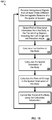
- FIG. 1B is a flow chart of an example process 150 for determining and using a spatial orientation of a body.
- the process 150 may be performed in part by the system shown in FIG. 1A .
- the process 150 begins with receiving navigational signals from at least three different electromagnetic beacons of a navigational system (152), for example, the signals from satellites 106 shown in FIG. 1A .
- the navigational signals can include an identification of the electromagnetic beacon (to distinguish the different signals received from different satellites) or the position of the electromagnetic beacon within the navigational frame, as well as a timestamp relating the time at which the transmission occurred, based upon a synchronized timing system.
- Partial directional information from the body to the transmitting beacon is detected for each of multiple received beacons.
- the partial directional information may include azimuth angle information and not elevation angle information (154).
- the partial directional information may include elevation angle information and not azimuth angle information.
- the partial directional information may be detected, for example, by the direction finding component 118 of FIG. 1A .
- the partial directional information can be determined using a directional transducer and receiver system.
- the directional transducer can be a physically rotating antenna or antenna array or an antenna array electrically rotated.
- an array of antenna elements can be electrically rotated by varying the phase of the exciting current in each of the elements of the array, and in so doing "rotating" the direction of receiving sensitivity of the array, or by applying a particular phase shift to the exciting current, and applying the exciting current to each antenna element in turn to rotate the directionality of the antenna array.
- the directional transducer may be too simple or inexpensive to properly detect elevation information.
- the position of the body is calculated (156). This may be done, for example, by the receiver of FIG 1A .
- the distance to the electromagnetic beacons can be calculated using time stamp information provided by the electromagnetic beacons and time-of-receipt information, as determined using a synchronized timing mechanism.
- the position of the body within the navigational frame can be calculated. For example, the capability to calculate the longitude, latitude and height of the body can be provided by a standard GPS receiver.
- the spatial orientation of the body is next calculated (158). This may be done, for example, by the body state estimator 108 of FIG. 1A .
- the detected partial directional information, the calculated position of the body, and the determined positions of the electromagnetic beacons can be used to calculate the spatial orientation of the body. The details of example calculations to obtain the spatial orientation are described in detail later in this document.
- the rate of change of the spatial orientation of the body is calculated (160). Based upon the spatial orientation calculation and detected rate of change of azimuth angle information (or alternatively, elevation angle information), the rate of change of spatial orientation can be calculated. The details of how this may be calculated are described in detail later in this document.
- This rate of change information may be stored in memory, for example in repository 110 of FIG. 1A , for later use.
- the travel of the body is controlled using the calculated information (162).
- the calculations for the position, spatial orientation, and rate of change of spatial orientation can be used to actively correct the course of the body or to provide feedback to an operator controlling the course of the body.
- the control of the body may be performed using the information stored, for example, in repository 110 of FIG. 1A .
- this stored information may serve as inputs to an on-board computer-controlled navigation system, and/or may be used to generate a visual display for a user.
- inertial sensors such as motion sensors (e.g., accelerometers) and/or rotation sensors (e.g., gyroscopes) have been employed to determine the orientation of a body as well as, optionally, the body velocity (e.g., direction and speed of movement).
- Many navigational systems employ GPS as well as inertial sensors, such as gyroscopes or accelerometers, to determine the six degrees of freedom (6DOF) of a body. These systems may be referred to as integrated GPS/inertial (GPSI) systems.
- GPS readings can be used to correct or calibrate readings provided by the Inertial Navigation System (INS).
- GPS calculations can be used to bound navigation errors occurring due to drift within the inertial sensors.
- the calculated spatial orientation and rate of change of spatial orientation can, in some implementations, be fed back to the system to bound inertial sensor navigation errors.
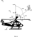
- FIG. 3A is an example diagram 300 of a helicopter 302 and a satellite 304, which will be used to illustrate an example body frame 312.
- FIG. 3A also illustrates a local navigation frame, which assuming yaw, pitch and roll angles all being zero as depicted in FIG. 3A , the local navigation frame would be the same as the body frame 312.
- FIG. 3A also illustrates a vector 306 from the body (helicopter 302) to the satellite representing a direction from which a line-of-sight transmission from the satellite 304 is received at the body, and angles that define the directional vector 306 in relation to the local navigation frame 312.
- the body frame (and local navigation frame) for the helicopter in this illustration is similar to the example aircraft body frame example discussed previously, and includes a z-axis 312c that is parallel with a forward facing direction of the helicopter, an x-axis 312a that extends up and down through the center of the helicopter and that is perpendicular to the z-axis 312c, and a y-axis that extends from side-to-side and through the center of the helicopter perpendicular to both the x-axis 312a and the z-axis 312c.
- the center point 312d of the body frame at which the three axes intersect is at the center of the rotor blades.
- the vector 306 from the center of the body frame 312d to the satellite 304 may be defined in relation to the local navigation frame in different ways.
- Determining the spatial orientation of the body includes solving the transformation between the coordinates for r and the coordinates of rb.
- a specialized sensor for example, a 2DOF directional antenna
- the transformation may then be determined using the vector measurements for two different satellites.
- a vector from the helicopter 302 to the satellite 304 could be described definitively using three angles, one angle from each of the three axes (x, y, and z), assuming the antenna system was of a type capable of detecting the three angles.
- the vector 306 as being a unit vector. As shown in FIG. 3A , for a unit vector rb 306, the vector direction from the body frame 312 of the helicopter 302 toward the satellite 304 is equivalent to three direction cosine angles.
- first "boresight" angle gamma_x 308 between a body frame x-axis 312a of the helicopter 302 and the satellite 304
- second "boresight” angle gamma_z 310 between the body frame z-axis 312c and the satellite 304.
- the third direction cosine angle gamma_y angle is the boresight angle taken with respect to the body frame y-axis 312b, which angle is not illustrated due to the perspective of FIG. 3A .
- gamma_x is equal to zero, then the body frame x-axis 312a is pointed directly at the satellite 304. Otherwise, the satellite 304 lies off axis.
- the second angle can be gamma_y or gamma_z 310, depending on whether the angle is measured with respect to the body frame y-axis 312b or the body frame z-axis 312c.
- a method of fully defining the direction vector 306 from a body to a beacon is measuring both an "elevation” angle and an "azimuth” angle relative to any designated one of the body frame axes 312a, 312b, or 312c.
- Any non-zero vector such as the body frame x-axis 312a, can determine a unique "normal" two-dimensional (2D) plane consisting of all the vectors from the center of the body frame 312 that are perpendicular to the body frame x-axis 312a.
- the body frame y-axis 312b and the body frame z-axis 312c are contained in the horizontal normal plane.
- the elevation angle for satellite 304 appears to be the same "boresight" angle gamma_z 310 due to the 2D perspective of the drawing showing vector 306 directly above the z-axis 312c. More generally, in a different perspective drawing, it may occur that the vector 306 is also rotated away from the z-axis 312c through an "azimuth" angle around the x-axis 312a, causing the boresight angle gamma_z 310 to be larger than the elevation angle above the horizontal plane.
- the helicopter 302 has an array of antennas 314a, 314b, and 314c arranged on the rotor blades of the helicopter.
- the antenna array receives transmissions from a satellite navigation system, including the satellite 304, which would be one of several satellites of the navigation system (the others not shown in FIG. 3A ).
- a satellite navigation system including the satellite 304, which would be one of several satellites of the navigation system (the others not shown in FIG. 3A ).
- the antennas rotate as the rotor blades rotate, and thus the antenna array has directional antenna capabilities.
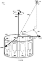
- a cylindrical antenna array 352 with a body frame 356 receives a transmission from an electromagnetic beacon 354 along a transmission vector 358.
- the transmission vector 358 can be defined by an azimuth angle 360 related to the offset of the transmission vector 358 from a body frame z-axis 356a and an elevation angle 362 related to the angle between the transmission vector 358 and a plane containing the z-axis 356a and a y-axis 356c.
- the vector 306 can thus be equivalently defined in terms of either three direction cosine angles or in terms of an azimuth angle and an elevation angle.
- the selection of the vertical x-axis 312a for determining azimuth angles is motivated by the horizontal configuration of the antenna array elements 314a, 314b, 314c on the helicopter rotor blades.
- the physical rotation of the antenna array 314a-c can modulate the electromagnetic signal from the beacon 304 and assist in measuring azimuth angles relative to the x-axis 312a.
- an inexpensive estimate of the body orientation may be made using partial directional information, for example, by using only scalar azimuth angle measurements, without requiring measurement of either elevation angles or direction cosines.
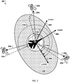
- FIG. 2 an example diagram 200 illustrates azimuth angle displacements of multiple beacons arranged around a body.
- An airplane 202 near the surface of the Earth is in communication with a set of three satellites 204a, 204b, and 204c orbiting the Earth.
- the orientation of the airplane 202 can be described in relation to a body frame 206a-c of the airplane 202.
- each of the satellites 204 in general terms, can be described using a set of vector measurements 208a, 208b, and 208c from the center of the body frame 206 to each satellite 204a, 204b, or 204c.
- the orientation of the body frame 206 can be determined simply by measuring the azimuth angles 210a, 210b, 210c.
- the azimuth angles are measured around an x-axis 206a using a y-axis 206c as a reference for zero azimuth angle.
- the azimuth angles 210a, 210b, 210c can be defined as follows.
- Any vector such as the body frame x-axis 206a, can define a unique "normal" two-dimensional (2D) plane 212 consisting of all the vectors from the center of the body frame 202 that are perpendicular to the body frame x-axis 206a.
- the body frame y-axis 206c and the body frame z-axis 206b are contained in the horizontal normal plane 212.
- the body frame 206 given any 3-vector in space that is not in the direction of the body frame x-axis 206a, such as the vector rb 208a, there is another unique 2D plane (not shown in FIG. 2 ) that contains both the body frame x-axis 206a and the vector rb 208a.
- This new plane is parallel to the body frame x-axis 206a, and it intersects the normal plane 212 in a line.
- This new plane establishes a correspondence between lines in the normal plane 212 and the planes that are parallel to the body frame x-axis 206a.
- the projected vector P*rb can be described using azimuth displacement angles mu_y 210 and mu_z (not illustrated) with respect to the body frame y-axis 206c and the body frame z-axis 206b, respectively. Note that these angles are not identical to the boresight angle gamma_y or the boresight angle gamma_z 310 (as described in relation to FIG. 3A ) because the angles in the normal plane 212 are not the same as angles in 3-space.
- mu_y 210 Since the body frame y-axis 206c and the body frame z-axis 206b are perpendicular, once mu_y 210 is known, mu_z can easily be derived, since the angles mu_y 210 and mu_z differ by ninety degrees. As such, a focus can be made upon measuring a single angle for each beacon, referred to as the azimuth angle mu_y 210, herein described as the angle of the projected vector P*rb in relation to the body frame y-axis 206c.
- a first azimuth angle 210a describes the position of a vector projected from the unit vector "r" 208a that extends from the center of the body frame 206 to the first beacon 204a.
- a second azimuth angle 210b describes the position of a vector projected from the unit vector "r" 208b that extends from the center of the body frame 206 to the second beacon 204b
- a third azimuth angle 210c describes the position of a vector projected from the unit vector "r" 208c that extends from the center of the body frame 206 to the third beacon 204c.
- equivalences can be used, for example, to construct an algorithm for determining body orientation based upon azimuth angle measurements even though the boresight angle gamma_x has not been measured.
- the azimuth angle measurements themselves, in some examples, can be determined using specialized sensors (e.g., included in the direction finding module 118 of the receiver 102, as described in relation to FIG. 1 ).
- the sensor(s) can additionally determine the derivative of each azimuth angle, also referred to as the azimuth angle rate.
- a directional transducer such as a rotatable antenna can be used to determine the azimuth of each beacon from the body position, disregarding the elevation of the beacon in relation to the normal plane.
- one or more antennas can be mounted upon the rotor blades of a helicopter, the rotation of the blades providing the rotation needed to effect direction finding with the antenna(s).
- an electrically rotated antenna array can be used to determine azimuth angle measurements.
- multiple antenna elements 366 can be mounted around the diameter of the cylindrical antenna array 352. The electrical phases of the antenna elements can be adjusted to create directional beams that are sensitive to azimuth angles.
- Changing the electrical phases can cause a rotation 364 of the directional beams of the cylindrical antenna array 352 around its body frame x-axis 356b.
- a cylindrical antenna array design can more accurately measure the azimuth angle mu_y 360 than the elevation angle 362. Without using the elevation angle 362, measuring the azimuth angle mu_y 360 provides the required partial information about the direction 358 to the beacon 354.
- the antenna array 352 is also used to measure the rate of change of the azimuth angle mu_y 360 as the body rotates or the beacon 354 moves.
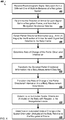
- FIG. 4 is a flow chart of an example process 400 for determining spatial orientation information for a body.
- the process 400 detects azimuth angle information and, optionally, rate of change of azimuth angle information related to three or more electromagnetic signal sets, each set originating from a different one of multiple beacons of a navigational system. Based upon the detected azimuth angle information, and not also requiring the detection of elevation angle information, the spatial orientation of the body can be estimated. Also, using the rate of change of the detected azimuth angle information, the angular velocity of the body can additionally be estimated.
- the process 400 in some examples, can be executed by the receiver 102 and the 6DOF body state estimator 108, as described in relation to FIG. 1 .
- the process 400 begins with receiving electromagnetic signal sets each from a different one of multiple beacons of a navigational system (402).
- Three or more beacons in communication range of a body for example, communicate electromagnetic signal sets which can be translated to determine the navigation direction or known position of each beacon, the beacons being at different positions relative to each other (e.g., not within a single line in relation to the body).
- the electromagnetic signal sets can be received by a directional transducer such as a rotatable antenna.
- the rotatable antenna can include one or more antennas positioned within a spinning body (e.g., missile or other projectile), such as a small microwave patch antenna mounted within and stationary in relation to the spinning body.
- a spinning body e.g., missile or other projectile
- an antenna or antenna array can be physically rotated around an axis with a defined orientation relative to the body (e.g., mounted on a rotating turntable within or upon the body, mounted on the rotor of a helicopter, etc.).
- the antenna pattern of an antenna array can be electrically rotated by causing the amplitude or phase of the antenna pattern to be rotated around an axis.
- the electromagnetic signal sets can arrive from a beacon within line-of-sight communication with the body, or the signal can be transferred to the body in a manner which allows the body to understand the navigation direction of the signal.
- the electromagnetic signal sets can be arriving from communication satellites such as GPS or GLONASS navigational satellites or land or water-based radio frequency beacons.
- the three beacons and the body are preferably not all within a single plane.
- the electromagnetic signal sets include information regarding the exact position of the beacon, referred to as ephemeris data.
- the ephemeris data can be derived through GPS format, Ephemerides of the Planets and the Moon (EPM) format (developed by the Russian Institute for Applied Astronomy of the Russian Academy of Sciences), or Integration Numécher Planétaire de l'Observatoire de Paris (INPOP) format (developed by the Institut de Mecanique Celeste et de Calcul des Ephemerides of France).
- EPM Ephemerides of the Planets and the Moon
- INPOP Integration Numérique Planétaire de l'Observatoire de Paris
- a receiver within the body in some implementations, can contain information which can be used to derive the known position or navigation direction of the beacon, such as by using a beacon identification code communicated to the body within the electromagnetic signal set.
- each electromagnetic signal set is transformed into a navigation reference data set (404).
- a receiver within the body can determine the position of the body (e.g., navigational coordinates of the center of the body frame) in relation to the known navigation frame.
- the reference data set in some implementations, can additionally include a velocity of the body.
- the reference data set in some examples, can be determined using standard GPS demodulation and processing methods.
- Azimuth angle information is detected for each electromagnetic signal set (406).
- the direction of a projected vector of the beacon in relation to a normal plane consisting of the body frame y- and z-axes can be detected by sampling the electromagnetic signal being communicated by the beacon to determine the point of peak signal amplitude.
- a directional transducer such as a rotatable antenna can be used to determine the direction in which each beacon exhibits the point of peak signal amplitude.
- a specialized sensor within the receiver of the body can measure the azimuth angle or the cosine of the azimuth angle relative to the body frame.
- the rate of change of the azimuth angle information is measured for each electromagnetic signal set (408).
- the azimuth rate of the beacon can be determined by measuring the alignment times for each beacon tracked by the receiver system and calculating a weighted sum of all of the collected alignment times.
- the rate at which the azimuth angle information is changing can be determined by processing multiple azimuth angle measurements in relation to time within the receiver.
- the receiver within the body can report measurements at five hertz or faster.
- the measurement period in some implementations, can be determined based in part upon the nature of the body. The determination of the rate of change of the orientation of a spinning body may require a shorter measurement period, for example, so that high frequency coning motions can be calculated with reasonable accuracy.
- the same number of measurements can be compiled for each beacon tracked (e.g., three or more GPS satellites). For example, if a particular measurement associated with a particular beacon is missed due to a communications problem, that beacon may be dropped from the calculation process when determining the rate of change of azimuth angle information.
- the detected azimuth angle information is transformed into a body measurement data set (410).
- the values mv and mw can be provided to the body state estimation module from the receiver or, alternatively, can be calculated by the body state estimation module based upon provided azimuth angle information.
- the format of the body measurement data set depends on how the body orientation will be described in a particular implementation.
- a three-by-three rotation matrix A such as a direction cosine matrix (DCM)
- DCM direction cosine matrix
- the three Euler angles in some implementations, can be directly manipulated, for example using a Newton method. Some switching between matrix calculations and Euler angle calculations, in some implementations, can be done while solving for spatial orientation as any of the above mentioned methods can be viewed as substantially equivalent.
- the rate of change of the azimuth angle information is transformed into a body measurement rate matrix (412).
- the format of the body measurement rate data set depends on how the body rates will be described in a particular implementation.
- the magnitude of the angular velocity vector can be used to specify the rate of rotation, for example, in complete cycles per second (e.g., Hertz), or mathematical radians per second.
- three components [p, q, r] can represent the combined rates of rotation of the body around the instantaneous position of the body axes.
- eulerdot yawdot pitchdot rolldot and the pqr components of the angular velocity.
- the entries in the matrix M2 can be derived from the components of the quaternion e in a similar manner as the entries of the matrix M1 depended on the Euler angles. Some switching between quaternion derivatives, Euler angle derivatives, and angular velocities can be done during calculations while solving for angular body rates as any of the above mentioned methods can be viewed as substantially equivalent.
- the spatial orientation of the body frame with respect to the known navigation frame is determined (414).
- the available information is contained in the body measurement data set and the navigation data set.
- the body measurement data set includes the cosines mv and mw for the azimuth angles.
- the body measurement data set does not include elevation angle information for the beacon (which is equivalent to the boresight angle gamma_x).
- Both the DCM A and the boresight angle gamma_x are unknown variables that can be found to determine the spatial orientation of the body frame. This is solved by minimizing a cost function J(A).
- a scalar optimization problem can be iteratively solved to estimate the body spatial orientation.
- the optimization produces a three-by-three DCM A that transforms from local navigation coordinates to body frame coordinates and estimates the unknown boresight angle gamma_x for each beacon.
- each measurement contribution to the solution can be weighted according to an estimation of the accuracy of the measurement. For example, the greater the number of measurements taken (e.g., measurements related to four or more beacons), the greater the accuracy which can be achieved.
- an approximation of the angular velocity of the body frame is iteratively refined (416).
- First an estimation of the angular velocity of the body frame can be initialized.
- the value used for initialization can vary, depending upon on the circumstances of the body. For example, if the body is known to be a spinning projectile, the angular velocity of the body frame may be initialized to a large rate. In another example, if the body is an airplane or helicopter beginning its flight pattern, the angular velocity of the body frame may be initialized based upon the vehicle acceleration. If previous estimates of the angular velocity of the body frame have been calculated, the initialization can be based in part upon a previous calculation.
- the initialized value can be used for estimating a DCM, Euler angle, or quaternion derivative.
- the rate matrices e.g., eulerdot or edot as described above
- the angular velocity of the body frame can then be calculated from the DCM, Euler angle, or quaternion derivative.
- a quadratic error value can be calculated. If this is not the first time performing the estimation iteration, the quadratic error value can be compared to the previously calculated quadratic error value to determine whether or not the estimation has achieved a desired degree of accuracy. If the comparison fails, the iteration process can continue with estimating the DCM, Euler angle, or quaternion derivative.
- the iterations can continue until the quadratic error value comparison determines that the current quadratic error value is equal to the previous quadratic error value for at least a predefined number of significant digits (e.g., 3, 4, or 6).
- the iterations may be discontinued, in some implementations, after a certain number of iterations or a certain amount of time has lapsed. For example, iterating on the angular velocity estimation can be cut short due to new measurements being available or to limit power consumption.
- the process 400 can include more or fewer steps, and some of the steps may be performed in a different sequence than those described.
- the rate of acceleration may be estimated.
- the position and velocity of the body is not calculated. For example, if the beacons are stationary, such as cellular telephone towers, and the position of the body is not desired, the process 400 can ignore position and velocity information, only calculating information related to the spatial orientation of the body. This may be applicable, for example, when providing heading information to an operator within a graphical display.
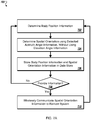
- FIG. 5 is a flow chart of an example process 500 for determining a spatial orientation of a body from azimuth angle information using quaternions.
- the information available to the process 500 can include the body measurement data set and the body navigation reference data sets, including the information related to the variables mw, mv, rb, and r as described in relation to FIG. 4 .
- the body navigation reference data sets can include N navigation vectors, defined within in the body frame, the navigation vector components arranged in a three-by-N matrix R (e.g., the columns being the N navigation vectors).
- R e.g., the columns being the N navigation vectors.
- an apostrophe within an equation or equivalence refers to taking the transpose of a vector or matrix.
- the goal of the process 500 is to determine the three-by-three direction cosine matrix (DCM) A that can be used to transform known navigation frame coordinates to body frame coordinates. If the coordinates of the body frame axes could be written as vectors in the known navigation frame, three different vectors u, v, and w could be used to define the xyz body frame axes as three-by-one column vectors in the known navigation frame.
- the navigation vectors r, azimuth angle cosine measurement mv, and azimuth angle cosine measurement mw are known values.
- the process 500 begins with initializing an attitude quaternion representing an estimate of a present attitude of the body frame (502). With the problem recast in terms of quaternions, it may be recognized that there are three independent unknown quantities in the unit quaternion e.
- a revised cost function J(A(e)) can be defined as a function of the unknown quaternion e, the known navigation vectors r, and the known azimuth angle cosine measurements mv and mw.
- H * e lambda * e
- H is a four-by-four angle eigenmatrix H derived from the vector measurements rb.
- the angle eigenmatrix H is unknown, being dependent upon the unknown boresight angles gamma_x as well as the known azimuth angle cosine measurements mv and mw. Using the scalar measurements, the angle eigenmatrix H can be simultaneously estimated while solving the eigenvector problem to determine the quaternion e, starting with approximate values for the boresight angles gamma_x.
- the cost function J(e) depends explicitly on the unknown parameter sgx, but the value of sgx implicitly depends on e.
- the eigenmatrix H implicitly depends on the parameter sgx.
- This eigenvector problem may be solved by four eigenvectors q with four different eigenvalues lambda.
- the desired attitude quaternion e in this example, is the eigenvector q with the largest eigenvalue lambda for the correct parameter sgx.
- an angle eigenmatrix H is established using reference values from the navigation reference data set and the body measurement data set (504).
- Three four-by-four matrices Hu, Hv and Hw that depend solely on the known navigation vectors r can be defined, demonstrating how the angle eigenmatrix H also depends on the unknown boresight angle gamma_x and the measured cosines mv and mw.
- H mv * Hv + mw * Hw + ctn * Hu
- a sum (or, optionally, a weighted sum) of the contributions for all N of the navigation vectors r can be formed.
- Data for at least three beacons, for example, may be required to determine a unique solution.
- the contribution for any navigation vector r with a small boresight angle gamma_x can be discounted because the cotangent is unbounded.
- matrices can be defined for each navigation vector r (1 through N).
- the navigation matrices for example, can be computed just a single time since they depend solely on the navigation vectors r in the matrix R.
- the navigation matrices can then be used in the following algorithms.
- the reference attitude quaternion and the angle eigenmatrix are iteratively refined (506).
- the core of the algorithm to compute the quaternion e includes an iterative process that refines an initial approximation of the quaternion e. Each time the iteration is performed, for example, the previous computation of the quaternion e becomes refined to provide a better approximation to the final quaternion e. The process can be repeated any number of times, but there can come a point where the estimate becomes dominated by the measurement errors.
- Variations of the quaternion refining algorithm can include, for example, different approaches for defining the initial estimate q for the quaternion e.
- anything that may be known about the approximate orientation of the body frame relative to the local navigation frame can be embedded in the initial estimate for q. This can include, in some examples, sensor measurements, initial path information regarding the vehicle, previously calculated spatial orientation estimates, or other measured or calculated estimations regarding the position, orientation, velocity, or acceleration of the body.
- quaternion method example just as the quaternion e is defined as a unit four-vector, each approximation q can be represented by a unit 4 four-vector.
- the cotangent estimates can now be used to recompute a four-by-four angle eigenmatrix H.
- the refined attitude quaternion is converted to equivalent yaw, pitch, and roll angles (508).
- the DCM or the Euler angles of yaw, pitch and roll can be derived from the quaternion estimate q using traditional methods expressing the equivalence between the different representations for the body orientation.
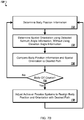
- FIG. 6 is a flow chart of an example process 600 for determining the angular rates of a body from azimuth angle rate information using quaternions. Similar to the method described in relation to FIG. 5 pertaining to the quaternion e and the angle eigenmatrix H, the quaternion derivative edot can be calculated given the derivatives of the azimuth angle cosine measurements mvdot and mwdot using a derivative matrix Hdot that depends on the derivatives of the azimuth angle cosine measurements mvdot and mwdot and the boresight angles gamma_x. Unlike the solution for the quaternion e, however, the quaternion derivative edot proves to not be an eigenvector of the derivative matrix Hdot.
- the eigenvectors of H can be carefully normalized in a manner that permits the quaternion derivative edot to be expressed as linear combinations of the eigenvectors H.
- the angle eigenmatrix H all of the eigenvalues are substantially distinct, and normalization can be carried out easily and efficiently.
- higher order quaternion derivatives can also be computed from higher order derivatives of the eigenmatrix (e.g., to determine body acceleration) using the following principles.
- the attitude quaternion e is the eigenvector of the angle eigenmatrix H that corresponds to the eigenvalue lambda.
- HmL H ⁇ lambda
- HmLdot Hdot ⁇ lambdadot
- HmL * edot ⁇ HmLdot * e
- HmL is singular and in the direction of the eigenvector quaternion e.
- edot can be considered as a sum of the other eigenvectors of the angle eigenmatrix H.
- Hdot HmL * edot ⁇ HmLdot * e 2
- the process 600 begins with initializing the angular velocity of the body frame (602).
- a three-by-one angular velocity vector pqr and other data structures must be initialized before the iterative refinement of the angular velocity begins.
- the angular velocity vector pqr can be initialized to a reasonable estimate of the angular velocity, for example based upon additional measurements available, a previous estimate, or other information known about the body. In some implementations, the angular velocity vector is initialized to zero.
- Hdot zeros 4 4 ;
- a quaternion derivative is calculated using the estimated angular velocity (604).
- the derivatives of the angle eigenmatrix and the eigenvalue are calculated (606).
- the derivatives Hdot and lambdadot for example, can be computed by the following process.
- the angular velocity is calculated using the derivatives (608).
- the angular velocity of the body frame is calculated from the quaternion derivative (608).
- the process 600 ends. Otherwise, the process 600 returns to estimating the quaternion derivative using the angular velocity of the body frame (604).
- FIG. 7A is a flow chart of an example process 700 for using spatial orientation estimates to provide feedback to a remote system.
- the remote system in some implementations, can use this information for testing (e.g., in determining whether a spinning projectile followed a path and coning model estimated by the designers), correcting (e.g., adjusting the path of a body which has gone off course), or controlling (e.g., actively adjusting the path of a body).
- a user at a remote control device could actively adjust the path of a pipeline drill based upon orientation measurements obtained through surface-mounted electromagnetic beacons and a body orientation estimator built into the pipeline drill.
- the process 700 begins with determining body position information (702).
- the body position information for example, can be determined in a conventional manner, such as through a GPS receiver.
- the body orientation is determined using detected azimuth angle information, without using elevation angle information (704). For example, using the process described in relation to FIG. 4 , the body orientation can be estimated.
- the body position information and the spatial orientation information are collected in a local data store (706).
- body position data and orientation estimate data can be collected within a data store directly connected to the body.
- the body position information and the spatial orientation information can be wirelessly communicated to a remote system (710).
- the data can be wirelessly communicated to the remote system each time it is calculated.
- sets of body position data and orientation estimate data can be collected, and the data provided to a remote system periodically.
- the data can be provided after every Nth iteration.
- the data can be provided on a fixed time schedule (e.g., every ten seconds).
- the body position data and the orientation estimate data in some implementations, can be provided to the remote system based upon meeting an error condition. For example, if the body orientation estimate data varies significantly from a planned navigational path, the remote system can be alerted.
- the process 700 returns to determining the body position information (702) based upon the current, and likely different, location and attitude of the body.
- FIG. 7B is a flow chart of an example process 720 for using spatial orientation estimates to adjust the trajectory of a body.
- the process 720 for example, can be used within the guidance system of a projectile, such as a missile or satellite, or an unmanned craft, such as a helicopter, submarine, or airplane.
- the process 720 begins with determining body position information (722).
- the body position information for example, can be determined in a conventional manner, such as through a GPS receiver.
- the body orientation is determined using detected azimuth angle information, without using elevation angle information (724). For example, using the process described in relation to FIG. 4 , the body orientation can be estimated.
- the body position information and the spatial orientation are compared to a desired path (726).
- a pre-determined trajectory or a flight plan can be programmed into a body attitude estimation module, such as the 6DOF body state estimator 108 described in relation to FIG. 1 .
- a threshold comparison can be made between the body position and estimated orientation and the desired path of the body.
- the body path can be adjusted to realign the body position and spatial orientation with the desired path (730).
- the difference between the pre-determined path and the current body position and orientation can be used to adjust the course of the body.
- the adjustment can be made through a flight system.
- passive adjustment elements such as wings, fins, or canards, can be adjusted to realign the body with the desired trajectory. If the body is a submarine, for example, the ballast system can be adjusted. Active elements, such as propulsion jets, for example, can be adjusted as well to realign the body.
- the process 720 returns to determining the body position information (722) based upon the current, and likely different, location and attitude of the body.
- FIG. 7C is a flow chart of an example process 740 for using spatial orientation estimates to provide visual feedback to the pilot or operator of a vehicle, such as an airplane, helicopter, truck, or submarine.
- the process 740 in some implementations, can provide a pilot with a visual indication during times when the pilot has limited access to actual visual indication of body orientation. For example, a pilot may have little or no indication of the attitude of the body when traveling through a silted or low visibility region of the ocean or when an airplane enters dense cloud cover.
- a cell phone display may be augmented with heading information such that a pedestrian could use the cell phone as a compass to walk out of a dense wooded area.
- the cell towers can act as navigation beacons for determining the orientation of a cell phone with an antenna capable of detecting azimuth information.
- the process 740 begins with determining the body orientation using detected azimuth angle information, without using elevation angle information (742). For example, using the process described in relation to FIG. 4 , the body orientation can be estimated.
- GUI graphical user interface
- a false horizon a simulation of the attitude of the body, or a representation of the attitude of the body frame in relation to the known navigation frame can be plotted graphically within a dashboard area of the vehicle controls or on a display area of a cell phone or remote control.
- Input is received from the user to adjust the spatial orientation (746).
- the user can manually adjust the orientation of the vehicle to realign the vehicle with the false horizon or to straighten the simulation of the attitude of the body.
- the GUI can be provided to a remote pilot from an unmanned vehicle.
- a pilot typically relying upon one or more camera images relayed from the unmanned vehicle can rely upon the process 740 to provide orientation feedback.
- FIG. 8 is a block diagram of a computing device 800 that may be used to implement the systems and methods described in this document.
- the computing device 800 may be used in a receiver (such as the receiver 102 shown in FIG. 1 ) or in a 6DOF body state estimator (such as the body state estimator 108 shown in FIG. 1 ).
- Computing device 800 includes a processor 802, memory 804, a storage device 806, input and output devices 808 such a data entry devices and graphical displays, and a bus system 810 that provides for communications between these components.
- the processor 802 can process instructions for execution within the computing device 800, including instructions stored in the memory 804 or on the storage device 806 to perform various operations described previously in this document.
- the components described in this specification may also be implemented in firmware or on an application specific integrated circuit (ASIC), in which case this FIG. 8 diagram is simply illustrative of device operation.
- ASIC application specific integrated circuit
- the features described may be implemented in digital electronic circuitry, or in computer hardware, firmware, software, or in combinations of them.
- the apparatus may be implemented in a computer program product tangibly embodied in an information carrier, e.g., in a machine-readable storage device for execution by a programmable processor; and method steps may be performed by a programmable processor executing a program of instructions to perform functions of the described implementations by operating on input data and generating output.
- the described features may be implemented advantageously in one or more computer programs that are executable on a programmable system including at least one programmable processor coupled to receive data and instructions from, and to transmit data and instructions to, a data storage system, at least one input device, and at least one output device.
- a computer program is a set of instructions that may be used, directly or indirectly, in a computer to perform a certain activity or bring about a certain result.
- a computer program may be written in any form of programming language, including compiled or interpreted languages, and it may be deployed in any form, including as a stand-alone program or as a module, component, subroutine, or other unit suitable for use in a computing environment.
- Suitable processors for the execution of a program of instructions include, by way of example, both general and special purpose microprocessors, and the sole processor or one of multiple processors of any kind of computer.
- a processor will receive instructions and data from a read-only memory or a random access memory or both.
- the essential elements of a computer are a processor for executing instructions and one or more memories for storing instructions and data.
- a computer will also include, or be operatively coupled to communicate with, one or more mass storage devices for storing data files; such devices include magnetic disks, such as internal hard disks and removable disks; magneto-optical disks; and optical disks.
- Storage devices suitable for tangibly embodying computer program instructions and data include all forms of non-volatile memory, including by way of example semiconductor memory devices, such as EPROM, EEPROM, and flash memory devices; magnetic disks such as internal hard disks and removable disks; magneto-optical disks; and CD-ROM and DVD-ROM disks.
- semiconductor memory devices such as EPROM, EEPROM, and flash memory devices
- magnetic disks such as internal hard disks and removable disks
- magneto-optical disks and CD-ROM and DVD-ROM disks.
- the processor and the memory may be supplemented by, or incorporated in, ASICs (application-specific integrated circuits).
- ASICs application-specific integrated circuits
- the features may be implemented on a computer having a display device such as a CRT (cathode ray tube) or LCD (liquid crystal display) monitor for displaying information to the user and a keyboard and a pointing device such as a mouse or a trackball by which the user may provide input to the computer.
- a display device such as a CRT (cathode ray tube) or LCD (liquid crystal display) monitor for displaying information to the user and a keyboard and a pointing device such as a mouse or a trackball by which the user may provide input to the computer.
- the features may be implemented in a computer system that includes a back-end component, such as a data server, or that includes a middleware component, such as an application server or an Internet server, or that includes a front-end component, such as a client computer having a graphical user interface or an Internet browser, or any combination of them.
- the components of the system may be connected by any form or medium of digital data communication such as a communication network. Examples of communication networks include, e.g., a LAN, a WAN, and the computers and networks forming the Internet.
- the computer system may include clients and servers.
- a client and server are generally remote from each other and typically interact through a network, such as the described one.
- the relationship of client and server arises by virtue of computer programs running on the respective computers and having a client-server relationship to each other.
Landscapes
- Engineering & Computer Science (AREA)
- Radar, Positioning & Navigation (AREA)
- Remote Sensing (AREA)
- Physics & Mathematics (AREA)
- General Physics & Mathematics (AREA)
- Computer Networks & Wireless Communication (AREA)
- Automation & Control Theory (AREA)
- Signal Processing (AREA)
- Position Fixing By Use Of Radio Waves (AREA)
- Navigation (AREA)
- Radar Systems Or Details Thereof (AREA)
Applications Claiming Priority (2)
| Application Number | Priority Date | Filing Date | Title |
|---|---|---|---|
| US12/786,137 US8779971B2 (en) | 2010-05-24 | 2010-05-24 | Determining spatial orientation information of a body from multiple electromagnetic signals |
| PCT/US2011/036993 WO2011149738A1 (en) | 2010-05-24 | 2011-05-18 | Determining spatial orientation information of a body from multiple electromagnetic signals |
Publications (2)
| Publication Number | Publication Date |
|---|---|
| EP2577343A1 EP2577343A1 (en) | 2013-04-10 |
| EP2577343B1 true EP2577343B1 (en) | 2017-10-11 |
Family
ID=44484135
Family Applications (1)
| Application Number | Title | Priority Date | Filing Date |
|---|---|---|---|
| EP11723151.4A Active EP2577343B1 (en) | 2010-05-24 | 2011-05-18 | Determining spatial orientation and angular rate of change of orientation information of a body from multiple electromagnetic signals |
Country Status (9)
Families Citing this family (63)
| Publication number | Priority date | Publication date | Assignee | Title |
|---|---|---|---|---|
| US8836848B2 (en) * | 2010-01-26 | 2014-09-16 | Southwest Research Institute | Vision system |
| US8779971B2 (en) | 2010-05-24 | 2014-07-15 | Robert J. Wellington | Determining spatial orientation information of a body from multiple electromagnetic signals |
| US8942964B2 (en) * | 2010-06-08 | 2015-01-27 | Southwest Research Institute | Optical state estimation and simulation environment for unmanned aerial vehicles |
| US9134131B2 (en) * | 2011-04-07 | 2015-09-15 | Icefield Tools Corporation | Method and apparatus for determining orientation using a plurality of angular rate sensors and accelerometers |
| US9651679B1 (en) * | 2011-04-13 | 2017-05-16 | Rockwell Collins, Inc. | Application of GPS signal processing to attitude determination and communication |
| US8466406B2 (en) | 2011-05-12 | 2013-06-18 | Southwest Research Institute | Wide-angle laser signal sensor having a 360 degree field of view in a horizontal plane and a positive 90 degree field of view in a vertical plane |
| SE536846C2 (sv) * | 2011-09-20 | 2014-09-30 | Bae Systems Bofors Ab | Metod och GNC-system för bestämning av rollvinkel hos en projektil |
| EP2773974B1 (en) * | 2011-11-02 | 2018-03-14 | Navin Systems Ltd. | Generating and using a location fingerprinting map |
| US9462210B2 (en) * | 2011-11-04 | 2016-10-04 | Remote TelePointer, LLC | Method and system for user interface for interactive devices using a mobile device |
| FI124586B (fi) * | 2012-02-03 | 2014-10-31 | Suunto Oy | Menetelmä ja laite korkeuden määrittämiseksi |
| KR101193833B1 (ko) * | 2012-06-29 | 2012-10-31 | 류동영 | 위성 추적 시스템 및 그 제어 방법 |
| JP5954126B2 (ja) * | 2012-11-14 | 2016-07-20 | 富士通株式会社 | 無線装置、制御方法、制御プログラム、及び、表示方法 |
| WO2014092625A1 (en) * | 2012-12-13 | 2014-06-19 | Minesto Ab | Method and system for controlling a flying wing |
| EP2932310A4 (en) | 2012-12-31 | 2016-10-12 | Halliburton Energy Services Inc | DEVICE AND METHOD FOR SEARCHING A POSITION IN A UNDERGROUND FORMATION |
| US10139516B2 (en) * | 2012-12-31 | 2018-11-27 | Halliburton Energy Services, Inc. | Apparatus and methods to find a position in an underground formation |
| US10203193B2 (en) | 2012-12-31 | 2019-02-12 | Halliburton Energy Services, Inc. | Apparatus and methods to find a position in an underground formation |
| FR3003960B1 (fr) * | 2013-03-27 | 2015-03-27 | Thales Sa | Procede de detection de signaux destines a leurrer un recepteur de signaux d'un systeme de navigation par satellites et recepteur associe. |
| FR3003961B1 (fr) * | 2013-03-27 | 2015-03-27 | Thales Sa | Procede de formation de faisceau signaux d'un recepteur de signaux d'un systeme de navigation par satellites pour ameliorer la resistance au brouillage. |
| US9429954B2 (en) | 2013-12-20 | 2016-08-30 | Google Inc. | Flight control for an airborne wind turbine |
| US10320073B2 (en) | 2014-01-14 | 2019-06-11 | Viasat, Inc. | Mobile terminal antenna alignment using arbitrary orientation attitude |
| US9910130B2 (en) * | 2014-02-10 | 2018-03-06 | The Boeing Company | Geo-location using known target co-calibration |
| KR101595791B1 (ko) * | 2014-04-03 | 2016-02-19 | 한국지질자원연구원 | 융합 알고리즘을 이용하여 센싱신호를 융합하는 센싱장치, 융합 방법, 및 복합 멤스 센서 경사계 |
| WO2016022579A2 (en) * | 2014-08-05 | 2016-02-11 | Massachusetts Institute Of Technology | Design of a free-space optical communication module for small satellites |
| US9945928B2 (en) * | 2014-10-30 | 2018-04-17 | Bastille Networks, Inc. | Computational signal processing architectures for electromagnetic signature analysis |
| JP2016099270A (ja) * | 2014-11-25 | 2016-05-30 | セイコーエプソン株式会社 | 位置算出方法、位置算出装置及び位置算出プログラム |
| US9846974B2 (en) * | 2014-12-05 | 2017-12-19 | Stmicroelectronics S.R.L. | Absolute rotation estimation including outlier detection via low-rank and sparse matrix decomposition |
| CN104503466B (zh) * | 2015-01-05 | 2017-09-12 | 北京健德乾坤导航系统科技有限责任公司 | 一种微小型无人机导航装置 |
| US10089887B2 (en) | 2015-03-06 | 2018-10-02 | Timothy Just | Drone encroachment avoidance monitor |
| US10665117B2 (en) | 2015-03-06 | 2020-05-26 | Timothy Just | Drone encroachment avoidance monitor |
| US9860145B2 (en) | 2015-07-02 | 2018-01-02 | Microsoft Technology Licensing, Llc | Recording of inter-application data flow |
| US10198252B2 (en) | 2015-07-02 | 2019-02-05 | Microsoft Technology Licensing, Llc | Transformation chain application splitting |
| US10261985B2 (en) | 2015-07-02 | 2019-04-16 | Microsoft Technology Licensing, Llc | Output rendering in dynamic redefining application |
| US9658836B2 (en) | 2015-07-02 | 2017-05-23 | Microsoft Technology Licensing, Llc | Automated generation of transformation chain compatible class |
| US9785484B2 (en) | 2015-07-02 | 2017-10-10 | Microsoft Technology Licensing, Llc | Distributed application interfacing across different hardware |
| US9712472B2 (en) | 2015-07-02 | 2017-07-18 | Microsoft Technology Licensing, Llc | Application spawning responsive to communication |
| US9733915B2 (en) | 2015-07-02 | 2017-08-15 | Microsoft Technology Licensing, Llc | Building of compound application chain applications |
| US9733993B2 (en) | 2015-07-02 | 2017-08-15 | Microsoft Technology Licensing, Llc | Application sharing using endpoint interface entities |
| US10031724B2 (en) | 2015-07-08 | 2018-07-24 | Microsoft Technology Licensing, Llc | Application operation responsive to object spatial status |
| US10198405B2 (en) | 2015-07-08 | 2019-02-05 | Microsoft Technology Licensing, Llc | Rule-based layout of changing information |
| US10277582B2 (en) | 2015-08-27 | 2019-04-30 | Microsoft Technology Licensing, Llc | Application service architecture |
| CA3006037C (en) | 2015-11-24 | 2020-09-08 | Drone Go Home, LLC | Drone defense system |
| CN106855582B (zh) * | 2015-12-08 | 2019-05-28 | 上海宇航系统工程研究所 | 卫星对日定向驱动装置地面六自由度加载测试系统 |
| US10241214B2 (en) * | 2016-03-01 | 2019-03-26 | International Business Machines Corporation | Acceleration of real time computer vision processing on UAVs through GPS attitude estimation |
| US10262546B2 (en) | 2016-04-13 | 2019-04-16 | Ge Aviation Systems Llc | Aircraft navigation using exponential map |
| WO2018035596A1 (en) * | 2016-08-25 | 2018-03-01 | Intelligent Sciences Ltd. | Aircraft acoustic position and orientation detection method and apparatus |
| US10432276B2 (en) * | 2016-09-29 | 2019-10-01 | Intel IP Corporation | Wireless link control and recovery using positional data |
| DE102016219935A1 (de) * | 2016-10-13 | 2018-04-19 | Continental Teves Ag & Co. Ohg | Vorrichtung und Verfahren zum Bestimmen einer Orientierung eines Fahrzeugs |
| CN106526532B (zh) * | 2016-10-31 | 2021-05-14 | 电子科技大学 | 一种基于四维天线阵的多普勒测向装置 |
| CN113804191B (zh) * | 2016-11-17 | 2024-03-19 | 格兰菲智能科技有限公司 | 移动设备及求取移动设备姿态的方法 |
| WO2018157103A1 (en) * | 2017-02-27 | 2018-08-30 | Northwestern University | Sensing and communication system for rotorcraft |
| SG11201908974XA (en) * | 2017-03-29 | 2019-10-30 | Agency Science Tech & Res | Real time robust localization via visual inertial odometry |
| US20210404811A1 (en) * | 2017-04-21 | 2021-12-30 | Shanghai Jiao Tong University | Method for solving attitude of rigid body based on function iterative integration |
| CN109708661B (zh) * | 2018-11-13 | 2022-07-29 | 河北汉光重工有限责任公司 | 一种具有两轴框架的惯性稳定设备的视轴惯性稳定方法 |
| JP7107820B2 (ja) * | 2018-11-13 | 2022-07-27 | 古野電気株式会社 | 測位装置、測位方法 |
| WO2020248209A1 (en) | 2019-06-14 | 2020-12-17 | Bayerische Motoren Werke Aktiengesellschaft | 3d odometry in 6d space with roadmodel 2d manifold |
| US12227203B2 (en) * | 2019-06-14 | 2025-02-18 | Bayerische Motoren Werke Aktiengesellschaft | Roadmodel manifold for 2D trajectory planner |
| RU2729459C1 (ru) * | 2020-02-05 | 2020-08-06 | Федеральное государственное бюджетное образовательное учреждение высшего образования "Рязанский государственный радиотехнический университет имени В.Ф. Уткина" | Способ определения пространственных координат и скоростей объектов сканирующей многопозиционной радиосистемой |
| CN115038973B (zh) * | 2020-05-29 | 2025-07-15 | 滴图(北京)科技有限公司 | 室内导航 |
| CN112697129B (zh) * | 2020-12-15 | 2023-05-05 | 电子科技大学 | 一种利用一维测角确定天线线阵二维姿态的快速方法 |
| CN112540617B (zh) * | 2020-12-16 | 2022-10-18 | 天奇自动化工程股份有限公司 | 移动平台的导航纠偏方法 |
| CN114459479B (zh) * | 2022-02-21 | 2024-12-24 | 北京航天嘉诚精密科技发展有限公司 | 旋转载体姿态、位置测量装置与方法 |
| KR102495685B1 (ko) * | 2022-06-30 | 2023-02-06 | 주식회사 티머니 | 자기장 강도의 결정방법 및 이를 위한 단말기 |
| KR102540637B1 (ko) * | 2022-10-27 | 2023-06-13 | 주식회사 모빌테크 | 다중 센서 동기화 방법 및 이를 실행하기 위하여 기록매체에 기록된 컴퓨터 프로그램 |
Family Cites Families (31)
| Publication number | Priority date | Publication date | Assignee | Title |
|---|---|---|---|---|
| US3701157A (en) | 1971-06-03 | 1972-10-24 | Us Air Force | Helicopter uhf antenna system for satellite communications |
| US3697994A (en) | 1971-07-19 | 1972-10-10 | Us Navy | Automatic beam steering technique for cylindrical-array radar antennas |
| US5101356A (en) | 1989-11-21 | 1992-03-31 | Unisys Corporation | Moving vehicle attitude measuring system |
| US5506588A (en) | 1993-06-18 | 1996-04-09 | Adroit Systems, Inc. | Attitude determining system for use with global positioning system, and laser range finder |
| US5841370A (en) | 1996-09-20 | 1998-11-24 | Lempicke; Thomas A. | Method and apparatus for determining aircraft bank angle using satellite navigational signals |
| US6088653A (en) | 1996-12-31 | 2000-07-11 | Sheikh; Suneel I. | Attitude determination method and system |
| WO1999003000A1 (en) | 1997-07-09 | 1999-01-21 | Massachusetts Institute Of Technology | Integrated flight information and control system |
| US6018315A (en) | 1998-05-04 | 2000-01-25 | Motorola, Inc. | Method and system for attitude sensing using monopulse GPS processing |
| US6278404B1 (en) * | 1998-07-08 | 2001-08-21 | The United States Of America As Represented By The United States National Aeronautics And Space Administration | Global positioning system satellite selection method |
| US6163021A (en) | 1998-12-15 | 2000-12-19 | Rockwell Collins, Inc. | Navigation system for spinning projectiles |
| AU2453501A (en) | 1999-12-21 | 2001-07-03 | Utilx Corporation | Long range electronic guidance system for locating a discrete in-ground boring device |
| JP2001235533A (ja) * | 2000-02-22 | 2001-08-31 | Maspro Denkoh Corp | 移動体の3次元位置及び3次元角度の検出方法とその検出装置 |
| AU775676B2 (en) | 2000-06-01 | 2004-08-12 | Furuno Electric Company, Limited | System for determining the heading and/or attitude of a body |
| US6580389B2 (en) | 2000-08-11 | 2003-06-17 | The Regents Of The University Of California | Attitude determination using a global positioning system |
| US6452543B1 (en) | 2001-05-24 | 2002-09-17 | Aerospace Corporation | GPS patch antenna attitude reference method |
| US6520448B1 (en) | 2001-06-12 | 2003-02-18 | Rockwell Collins, Inc. | Spinning-vehicle navigation using apparent modulation of navigational signals |
| US6587761B2 (en) | 2001-10-23 | 2003-07-01 | The Aerospace Corporation | Unambiguous integer cycle attitude determination method |
| US6782320B1 (en) | 2002-05-16 | 2004-08-24 | The United States Of America As Represented By The Secretary Of The Army | Method and system of single-antenna determination of position, time, and attitude of a moving object by satellite navigation |
| US6784840B2 (en) | 2002-12-23 | 2004-08-31 | Itt Manufacturing Enterprises, Inc. | Method for determining azimuth and elevation angles using a single axis direction finding system |
| JP2004233185A (ja) | 2003-01-30 | 2004-08-19 | Yokogawa Electric Corp | 高機能gpsとそれを用いた航法装置 |
| US7904243B2 (en) * | 2004-01-15 | 2011-03-08 | The Boeing Company | Real-time data aiding for enhanced GPS performance |
| US7268727B2 (en) * | 2004-04-30 | 2007-09-11 | Paul Yalden Montgomery | Method and apparatus for improved position, velocity, orientation or angular rate sensor |
| US7395987B2 (en) | 2005-07-26 | 2008-07-08 | Honeywell International Inc. | Apparatus and appertaining method for upfinding in spinning projectiles using a phase-lock-loop or correlator mechanism |
| US8275544B1 (en) * | 2005-11-21 | 2012-09-25 | Miltec Missiles & Space | Magnetically stabilized forward observation platform |
| CA2633529C (en) | 2005-12-16 | 2014-10-21 | Raytheon Utd Inc. | Positioning system and method |
| WO2007143806A2 (en) * | 2006-06-15 | 2007-12-21 | Uti Limited Partnership | Vehicular navigation and positioning system |
| US7397422B2 (en) | 2006-09-19 | 2008-07-08 | The Boeing Company | Method and system for attitude determination of a platform using global navigation satellite system and a steered antenna |
| US8305265B2 (en) * | 2007-05-29 | 2012-11-06 | Toyon Research Corporation | Radio-based direction-finding navigation system using small antenna |
| US20110050903A1 (en) * | 2009-04-08 | 2011-03-03 | Topcon Positioning Systems, Inc. | Method for determining position and orientation of vehicle trailers |
| US20110161038A1 (en) * | 2009-12-29 | 2011-06-30 | Jeff Sutherland | System and Method for Calibration of Mounted Acoustic Monitoring System with Mapping Unit |
| US8779971B2 (en) | 2010-05-24 | 2014-07-15 | Robert J. Wellington | Determining spatial orientation information of a body from multiple electromagnetic signals |
-
2010
- 2010-05-24 US US12/786,137 patent/US8779971B2/en active Active
-
2011
- 2011-05-18 KR KR1020127033695A patent/KR101809294B1/ko active Active
- 2011-05-18 CA CA2837179A patent/CA2837179C/en active Active
- 2011-05-18 NZ NZ605019A patent/NZ605019A/en not_active IP Right Cessation
- 2011-05-18 AU AU2011258700A patent/AU2011258700B2/en active Active
- 2011-05-18 WO PCT/US2011/036993 patent/WO2011149738A1/en active Application Filing
- 2011-05-18 JP JP2013512083A patent/JP2013533467A/ja active Pending
- 2011-05-18 EP EP11723151.4A patent/EP2577343B1/en active Active
-
2012
- 2012-11-22 IL IL223186A patent/IL223186A/en active IP Right Grant
-
2014
- 2014-05-22 US US14/285,324 patent/US9719788B2/en active Active
Non-Patent Citations (1)
| Title |
|---|
| None * |
Also Published As
| Publication number | Publication date |
|---|---|
| AU2011258700A1 (en) | 2013-01-10 |
| US8779971B2 (en) | 2014-07-15 |
| IL223186A0 (en) | 2013-02-03 |
| CA2837179A1 (en) | 2011-12-01 |
| IL223186A (en) | 2016-07-31 |
| KR20130093526A (ko) | 2013-08-22 |
| JP2013533467A (ja) | 2013-08-22 |
| US20140336929A1 (en) | 2014-11-13 |
| WO2011149738A1 (en) | 2011-12-01 |
| CA2837179C (en) | 2015-12-15 |
| NZ605019A (en) | 2014-12-24 |
| KR101809294B1 (ko) | 2017-12-14 |
| EP2577343A1 (en) | 2013-04-10 |
| US20110285590A1 (en) | 2011-11-24 |
| AU2011258700B2 (en) | 2015-07-02 |
| US9719788B2 (en) | 2017-08-01 |
Similar Documents
| Publication | Publication Date | Title |
|---|---|---|
| EP2577343B1 (en) | Determining spatial orientation and angular rate of change of orientation information of a body from multiple electromagnetic signals | |
| EP2570823B1 (en) | Method and apparatus for differential global positioning system (DGPS) - based real time attitude determination (RTAD) | |
| US6587761B2 (en) | Unambiguous integer cycle attitude determination method | |
| US4405986A (en) | GSP/Doppler sensor velocity derived attitude reference system | |
| US9658071B2 (en) | System and method of determining a position of a remote object via one or more images | |
| Willi et al. | GNSS attitude determination with non-synchronized receivers and short baselines onboard a spacecraft | |
| Vetrella et al. | Satellite and vision-aided sensor fusion for cooperative navigation of unmanned aircraft swarms | |
| CN112394381B (zh) | 基于球卫星的全自主月面导航和数据通信方法 | |
| US9217639B1 (en) | North-finding using inertial navigation system | |
| RU2633703C1 (ru) | Интегрированная инерциально-спутниковая система ориентации и навигации | |
| Emel’yantsev et al. | Improving the accuracy of GPS compass for small-sized objects | |
| US20170108590A1 (en) | Triple difference formulation for formation flight | |
| US6782320B1 (en) | Method and system of single-antenna determination of position, time, and attitude of a moving object by satellite navigation | |
| JP2008241079A (ja) | 航法システム | |
| Łabowski et al. | Inertial navigation system for radar terrain imaging | |
| EP4336145A1 (en) | Method and system for determining initial heading angle | |
| Consoli et al. | A multi-antenna approach for UAV's attitude determination | |
| Chicarella et al. | Improvement of GPR tracking by using inertial and GPS combined data | |
| Capuano et al. | GNSS based attitude determination systems for nanosatellites | |
| US12228406B2 (en) | Multi-agent navigation | |
| Um et al. | Space flight test results for the SOAR experiment | |
| Sollie | Estimation of uav position, velocity and attitude using tightly coupled integration of imu and a dual gnss receiver setup | |
| Wang et al. | An Attitude Data Measurement System Based on Dual-Band Antenna Direction Finding | |
| Biswas | GPS–INS Newly Proposed Integrated System Based on Kalman Filter and Complementary Filter for Aircraft Position Determination | |
| Hongyan et al. | The accurate model for beam synchronization in spaceborne/airborne hybrid bistatic SAR |
Legal Events
| Date | Code | Title | Description |
|---|---|---|---|
| PUAI | Public reference made under article 153(3) epc to a published international application that has entered the european phase |
Free format text: ORIGINAL CODE: 0009012 |
|
| 17P | Request for examination filed |
Effective date: 20121221 |
|
| AK | Designated contracting states |
Kind code of ref document: A1 Designated state(s): AL AT BE BG CH CY CZ DE DK EE ES FI FR GB GR HR HU IE IS IT LI LT LU LV MC MK MT NL NO PL PT RO RS SE SI SK SM TR |
|
| DAX | Request for extension of the european patent (deleted) | ||
| GRAP | Despatch of communication of intention to grant a patent |
Free format text: ORIGINAL CODE: EPIDOSNIGR1 |
|
| INTG | Intention to grant announced |
Effective date: 20161216 |
|
| GRAJ | Information related to disapproval of communication of intention to grant by the applicant or resumption of examination proceedings by the epo deleted |
Free format text: ORIGINAL CODE: EPIDOSDIGR1 |
|
| INTC | Intention to grant announced (deleted) | ||
| GRAP | Despatch of communication of intention to grant a patent |
Free format text: ORIGINAL CODE: EPIDOSNIGR1 |
|
| INTG | Intention to grant announced |
Effective date: 20170719 |
|
| GRAS | Grant fee paid |
Free format text: ORIGINAL CODE: EPIDOSNIGR3 |
|
| GRAA | (expected) grant |
Free format text: ORIGINAL CODE: 0009210 |
|
| AK | Designated contracting states |
Kind code of ref document: B1 Designated state(s): AL AT BE BG CH CY CZ DE DK EE ES FI FR GB GR HR HU IE IS IT LI LT LU LV MC MK MT NL NO PL PT RO RS SE SI SK SM TR |
|
| REG | Reference to a national code |
Ref country code: GB Ref legal event code: FG4D |
|
| REG | Reference to a national code |
Ref country code: CH Ref legal event code: EP |
|
| REG | Reference to a national code |
Ref country code: IE Ref legal event code: FG4D |
|
| REG | Reference to a national code |
Ref country code: AT Ref legal event code: REF Ref document number: 936526 Country of ref document: AT Kind code of ref document: T Effective date: 20171115 |
|
| REG | Reference to a national code |
Ref country code: DE Ref legal event code: R096 Ref document number: 602011042293 Country of ref document: DE |
|
| REG | Reference to a national code |
Ref country code: NL Ref legal event code: MP Effective date: 20171011 |
|
| REG | Reference to a national code |
Ref country code: LT Ref legal event code: MG4D |
|
| REG | Reference to a national code |
Ref country code: AT Ref legal event code: MK05 Ref document number: 936526 Country of ref document: AT Kind code of ref document: T Effective date: 20171011 |
|
| PG25 | Lapsed in a contracting state [announced via postgrant information from national office to epo] |
Ref country code: NL Free format text: LAPSE BECAUSE OF FAILURE TO SUBMIT A TRANSLATION OF THE DESCRIPTION OR TO PAY THE FEE WITHIN THE PRESCRIBED TIME-LIMIT Effective date: 20171011 |
|
| PG25 | Lapsed in a contracting state [announced via postgrant information from national office to epo] |
Ref country code: SE Free format text: LAPSE BECAUSE OF FAILURE TO SUBMIT A TRANSLATION OF THE DESCRIPTION OR TO PAY THE FEE WITHIN THE PRESCRIBED TIME-LIMIT Effective date: 20171011 Ref country code: ES Free format text: LAPSE BECAUSE OF FAILURE TO SUBMIT A TRANSLATION OF THE DESCRIPTION OR TO PAY THE FEE WITHIN THE PRESCRIBED TIME-LIMIT Effective date: 20171011 Ref country code: NO Free format text: LAPSE BECAUSE OF FAILURE TO SUBMIT A TRANSLATION OF THE DESCRIPTION OR TO PAY THE FEE WITHIN THE PRESCRIBED TIME-LIMIT Effective date: 20180111 Ref country code: LT Free format text: LAPSE BECAUSE OF FAILURE TO SUBMIT A TRANSLATION OF THE DESCRIPTION OR TO PAY THE FEE WITHIN THE PRESCRIBED TIME-LIMIT Effective date: 20171011 |
|
| REG | Reference to a national code |
Ref country code: FR Ref legal event code: PLFP Year of fee payment: 8 |
|
| PG25 | Lapsed in a contracting state [announced via postgrant information from national office to epo] |
Ref country code: LV Free format text: LAPSE BECAUSE OF FAILURE TO SUBMIT A TRANSLATION OF THE DESCRIPTION OR TO PAY THE FEE WITHIN THE PRESCRIBED TIME-LIMIT Effective date: 20171011 Ref country code: GR Free format text: LAPSE BECAUSE OF FAILURE TO SUBMIT A TRANSLATION OF THE DESCRIPTION OR TO PAY THE FEE WITHIN THE PRESCRIBED TIME-LIMIT Effective date: 20180112 Ref country code: AT Free format text: LAPSE BECAUSE OF FAILURE TO SUBMIT A TRANSLATION OF THE DESCRIPTION OR TO PAY THE FEE WITHIN THE PRESCRIBED TIME-LIMIT Effective date: 20171011 Ref country code: RS Free format text: LAPSE BECAUSE OF FAILURE TO SUBMIT A TRANSLATION OF THE DESCRIPTION OR TO PAY THE FEE WITHIN THE PRESCRIBED TIME-LIMIT Effective date: 20171011 Ref country code: IS Free format text: LAPSE BECAUSE OF FAILURE TO SUBMIT A TRANSLATION OF THE DESCRIPTION OR TO PAY THE FEE WITHIN THE PRESCRIBED TIME-LIMIT Effective date: 20180211 Ref country code: HR Free format text: LAPSE BECAUSE OF FAILURE TO SUBMIT A TRANSLATION OF THE DESCRIPTION OR TO PAY THE FEE WITHIN THE PRESCRIBED TIME-LIMIT Effective date: 20171011 Ref country code: BG Free format text: LAPSE BECAUSE OF FAILURE TO SUBMIT A TRANSLATION OF THE DESCRIPTION OR TO PAY THE FEE WITHIN THE PRESCRIBED TIME-LIMIT Effective date: 20180111 |
|
| REG | Reference to a national code |
Ref country code: DE Ref legal event code: R097 Ref document number: 602011042293 Country of ref document: DE |
|
| PG25 | Lapsed in a contracting state [announced via postgrant information from national office to epo] |
Ref country code: DK Free format text: LAPSE BECAUSE OF FAILURE TO SUBMIT A TRANSLATION OF THE DESCRIPTION OR TO PAY THE FEE WITHIN THE PRESCRIBED TIME-LIMIT Effective date: 20171011 Ref country code: EE Free format text: LAPSE BECAUSE OF FAILURE TO SUBMIT A TRANSLATION OF THE DESCRIPTION OR TO PAY THE FEE WITHIN THE PRESCRIBED TIME-LIMIT Effective date: 20171011 Ref country code: CZ Free format text: LAPSE BECAUSE OF FAILURE TO SUBMIT A TRANSLATION OF THE DESCRIPTION OR TO PAY THE FEE WITHIN THE PRESCRIBED TIME-LIMIT Effective date: 20171011 Ref country code: SK Free format text: LAPSE BECAUSE OF FAILURE TO SUBMIT A TRANSLATION OF THE DESCRIPTION OR TO PAY THE FEE WITHIN THE PRESCRIBED TIME-LIMIT Effective date: 20171011 |
|
| PLBE | No opposition filed within time limit |
Free format text: ORIGINAL CODE: 0009261 |
|
| STAA | Information on the status of an ep patent application or granted ep patent |
Free format text: STATUS: NO OPPOSITION FILED WITHIN TIME LIMIT |
|
| PG25 | Lapsed in a contracting state [announced via postgrant information from national office to epo] |
Ref country code: PL Free format text: LAPSE BECAUSE OF FAILURE TO SUBMIT A TRANSLATION OF THE DESCRIPTION OR TO PAY THE FEE WITHIN THE PRESCRIBED TIME-LIMIT Effective date: 20171011 Ref country code: RO Free format text: LAPSE BECAUSE OF FAILURE TO SUBMIT A TRANSLATION OF THE DESCRIPTION OR TO PAY THE FEE WITHIN THE PRESCRIBED TIME-LIMIT Effective date: 20171011 Ref country code: IT Free format text: LAPSE BECAUSE OF FAILURE TO SUBMIT A TRANSLATION OF THE DESCRIPTION OR TO PAY THE FEE WITHIN THE PRESCRIBED TIME-LIMIT Effective date: 20171011 Ref country code: SM Free format text: LAPSE BECAUSE OF FAILURE TO SUBMIT A TRANSLATION OF THE DESCRIPTION OR TO PAY THE FEE WITHIN THE PRESCRIBED TIME-LIMIT Effective date: 20171011 |
|
| 26N | No opposition filed |
Effective date: 20180712 |
|
| PG25 | Lapsed in a contracting state [announced via postgrant information from national office to epo] |
Ref country code: SI Free format text: LAPSE BECAUSE OF FAILURE TO SUBMIT A TRANSLATION OF THE DESCRIPTION OR TO PAY THE FEE WITHIN THE PRESCRIBED TIME-LIMIT Effective date: 20171011 |
|
| REG | Reference to a national code |
Ref country code: CH Ref legal event code: PL |
|
| REG | Reference to a national code |
Ref country code: BE Ref legal event code: MM Effective date: 20180531 |
|
| PG25 | Lapsed in a contracting state [announced via postgrant information from national office to epo] |
Ref country code: MC Free format text: LAPSE BECAUSE OF FAILURE TO SUBMIT A TRANSLATION OF THE DESCRIPTION OR TO PAY THE FEE WITHIN THE PRESCRIBED TIME-LIMIT Effective date: 20171011 |
|
| REG | Reference to a national code |
Ref country code: IE Ref legal event code: MM4A |
|
| PG25 | Lapsed in a contracting state [announced via postgrant information from national office to epo] |
Ref country code: CH Free format text: LAPSE BECAUSE OF NON-PAYMENT OF DUE FEES Effective date: 20180531 Ref country code: LI Free format text: LAPSE BECAUSE OF NON-PAYMENT OF DUE FEES Effective date: 20180531 |
|
| PG25 | Lapsed in a contracting state [announced via postgrant information from national office to epo] |
Ref country code: LU Free format text: LAPSE BECAUSE OF NON-PAYMENT OF DUE FEES Effective date: 20180518 |
|
| PG25 | Lapsed in a contracting state [announced via postgrant information from national office to epo] |
Ref country code: IE Free format text: LAPSE BECAUSE OF NON-PAYMENT OF DUE FEES Effective date: 20180518 |
|
| PG25 | Lapsed in a contracting state [announced via postgrant information from national office to epo] |
Ref country code: BE Free format text: LAPSE BECAUSE OF NON-PAYMENT OF DUE FEES Effective date: 20180531 |
|
| PG25 | Lapsed in a contracting state [announced via postgrant information from national office to epo] |
Ref country code: MT Free format text: LAPSE BECAUSE OF NON-PAYMENT OF DUE FEES Effective date: 20180518 |
|
| PG25 | Lapsed in a contracting state [announced via postgrant information from national office to epo] |
Ref country code: TR Free format text: LAPSE BECAUSE OF FAILURE TO SUBMIT A TRANSLATION OF THE DESCRIPTION OR TO PAY THE FEE WITHIN THE PRESCRIBED TIME-LIMIT Effective date: 20171011 |
|
| PG25 | Lapsed in a contracting state [announced via postgrant information from national office to epo] |
Ref country code: PT Free format text: LAPSE BECAUSE OF FAILURE TO SUBMIT A TRANSLATION OF THE DESCRIPTION OR TO PAY THE FEE WITHIN THE PRESCRIBED TIME-LIMIT Effective date: 20171011 Ref country code: HU Free format text: LAPSE BECAUSE OF FAILURE TO SUBMIT A TRANSLATION OF THE DESCRIPTION OR TO PAY THE FEE WITHIN THE PRESCRIBED TIME-LIMIT; INVALID AB INITIO Effective date: 20110518 |
|
| PG25 | Lapsed in a contracting state [announced via postgrant information from national office to epo] |
Ref country code: CY Free format text: LAPSE BECAUSE OF FAILURE TO SUBMIT A TRANSLATION OF THE DESCRIPTION OR TO PAY THE FEE WITHIN THE PRESCRIBED TIME-LIMIT Effective date: 20171011 Ref country code: MK Free format text: LAPSE BECAUSE OF NON-PAYMENT OF DUE FEES Effective date: 20171011 |
|
| PG25 | Lapsed in a contracting state [announced via postgrant information from national office to epo] |
Ref country code: AL Free format text: LAPSE BECAUSE OF FAILURE TO SUBMIT A TRANSLATION OF THE DESCRIPTION OR TO PAY THE FEE WITHIN THE PRESCRIBED TIME-LIMIT Effective date: 20171011 |
|
| PGFP | Annual fee paid to national office [announced via postgrant information from national office to epo] |
Ref country code: FR Payment date: 20220525 Year of fee payment: 12 Ref country code: DE Payment date: 20220527 Year of fee payment: 12 |
|
| PGFP | Annual fee paid to national office [announced via postgrant information from national office to epo] |
Ref country code: FI Payment date: 20220527 Year of fee payment: 12 |
|
| REG | Reference to a national code |
Ref country code: DE Ref legal event code: R119 Ref document number: 602011042293 Country of ref document: DE |
|
| PG25 | Lapsed in a contracting state [announced via postgrant information from national office to epo] |
Ref country code: FI Free format text: LAPSE BECAUSE OF NON-PAYMENT OF DUE FEES Effective date: 20230518 |
|
| PG25 | Lapsed in a contracting state [announced via postgrant information from national office to epo] |
Ref country code: DE Free format text: LAPSE BECAUSE OF NON-PAYMENT OF DUE FEES Effective date: 20231201 |
|
| PG25 | Lapsed in a contracting state [announced via postgrant information from national office to epo] |
Ref country code: FR Free format text: LAPSE BECAUSE OF NON-PAYMENT OF DUE FEES Effective date: 20230531 |
|
| PGFP | Annual fee paid to national office [announced via postgrant information from national office to epo] |
Ref country code: GB Payment date: 20240524 Year of fee payment: 14 |