EP2576314B1 - Closure for railway switch actuating devices - Google Patents
Closure for railway switch actuating devices Download PDFInfo
- Publication number
- EP2576314B1 EP2576314B1 EP11725887.1A EP11725887A EP2576314B1 EP 2576314 B1 EP2576314 B1 EP 2576314B1 EP 11725887 A EP11725887 A EP 11725887A EP 2576314 B1 EP2576314 B1 EP 2576314B1
- Authority
- EP
- European Patent Office
- Prior art keywords
- bolt
- guide
- locking
- tongue
- hinge
- Prior art date
- Legal status (The legal status is an assumption and is not a legal conclusion. Google has not performed a legal analysis and makes no representation as to the accuracy of the status listed.)
- Not-in-force
Links
Images

Classifications
-
- E—FIXED CONSTRUCTIONS
- E01—CONSTRUCTION OF ROADS, RAILWAYS, OR BRIDGES
- E01B—PERMANENT WAY; PERMANENT-WAY TOOLS; MACHINES FOR MAKING RAILWAYS OF ALL KINDS
- E01B7/00—Switches; Crossings
- E01B7/20—Safety means for switches, e.g. switch point protectors, auxiliary or guiding rail members
-
- B—PERFORMING OPERATIONS; TRANSPORTING
- B61—RAILWAYS
- B61L—GUIDING RAILWAY TRAFFIC; ENSURING THE SAFETY OF RAILWAY TRAFFIC
- B61L5/00—Local operating mechanisms for points or track-mounted scotch-blocks; Visible or audible signals; Local operating mechanisms for visible or audible signals
- B61L5/10—Locking mechanisms for points; Means for indicating the setting of points
Definitions
- the invention relates to a closure for points setting devices, with a closure piece which forms a running in the adjustment direction of the switch guide slot and a transversely outgoing from the guide slot locking seat, a displaceable in the guide slot guide pin, connected to a remote switch blade hinge pin, and a bearing block, the is pivotable about the axis of the guide pin and in which the guide pin (and the hinge pin are mounted.
- Turnouts for rail vehicles have two switch points, which are pivotally located between so-called stock rails of a switch and can be adjusted in the direction transverse to the stock rails with the aid of the points setter.
- the adjacent tongue In each stationary state of the switch machine is one of the two switch blades on the associated stock rail. It is therefore called the adjacent tongue.
- the other switch tongue is referred to as a remote tongue, since its free end to the associated stock rail has a certain distance.
- the closure serves to positively block the adjacent switch blade in the adjacent position, so that they can not be moved away from the stock rail, as this could lead to derailment of the rail vehicle.
- the point setting device must therefore have an unlocking mechanism which unlocks the closure before the actual changeover process can begin.
- the object of the invention is to provide a novel closure for switches setting devices, which is characterized by a high reliability and a compact design.
- a hingedly connected to an adjacent switch blade locking lever carries at the remote from the switch blade end lockable on a locking lock pin
- the locking pin, the guide pin and the hinge pin are mounted in a triangular configuration in such a positional block that the locking pin and the hinge pin lie on opposite sides of the guide slot and the adjacent switch blades are closer than the guide pin, and that a spring biases the remote switch blade towards its remote position. If a force acting on the remote switch blade and thus on the hinge pin, which tends to move the remote switch blade into its adjacent position, the adjacent tongue remains initially blocked in its adjacent position, since the locking pin rests against the locking seat. On the bearing block then acts a torque which has the tendency to pivot the bearing block about the axis of the guide pin. Due to this pivoting movement of the locking pin enters the guide slot, so that it comes free from the locking seat.
- the spring can yield slightly during this process and thus makes it possible for the hinge pin to move in accordance with the pivoting movement of the bearing block.
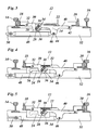
- a switch 10 for rail vehicles a closure 12 of an associated switch device are shown.
- the switch 10 has two stock rails 14, 16 and two switch blades 18, 20.
- the switch blade 18 is located on the stock rail 14 (adjacent tongue), while the switch blade 20 is moved away from the stock rail 16 (tongue off).
- the closure 12 has a stationary between the jaw rails 14, 16 arranged closure piece 22 which forms a transverse to the cheek rails guide slot 24.
- the guide slot 24 is formed by a straight on the largest part of its length in a wall of the closure piece 22 extending slot, which at one end, left in Fig. 1 is extended, so that a transversely of the guide slot 24 outgoing locking seat 26 is formed for a locking pin 28.
- the locking pin 28 is seated at the free end of a Z-shaped angled locking lever 30 which is connected at the other end by a hinge 32 with the adjacent switch blade 18.
- the locking lever 30 and the voltage applied to the locking seat 26 locking pin 28 thus ensure that the adjacent switch blade 18 is positively locked in the adjacent position. Since the axis of the hinge 32 is horizontal and the locking seat 26 is formed on the underside of the guide slot 24, the weight of the locking lever 30 contributes to the fact that the locking pin 28 reliably engages in the locking position.
- the locking pin 28 is held in a bearing block 34, which also receives a guide pin 36 and a hinge pin 38.
- the hinge pin 38 connects the bearing block 34 articulated to a connecting member 40, which in turn is connected via a hinge 42 with the remote switch blade 20.
- the axes of the locking pin 28, the guide pin 36 and the hinge pin 38 form a triangle.
- the guide pin 36 is slidably guided in the guide slot 24.
- the locking pin 28 and the hinge pin 38 are offset from the guide pin 36 to the adjacent switch blade 18 out and lie on opposite sides (below and above) of the central axis of the guide slot 24th
- the connecting member 40 has in the middle between the hinge pin 38 and the joint 42 on a downwardly projecting lug 44 on which a spring 46 engages via a hinge 46.
- the other end of the spring 48 is connected in the example shown here via a control rod 50 with a drive, not shown, of the point setting device.
- the entire closure 12 is housed in a box-shaped housing 52, which is arranged below the stock rails 14, 16 and in the area between the stock rails slightly higher drawn side walls, between which the closure piece 22 is held.
- the closure 12 has a total of a symmetrical structure, wherein the plane of symmetry by the locking lever 30 and the connecting member 40 is defined.
- the closure piece 22 has in plan a C-shaped configuration with lying symmetrically to the locking lever 30 side walls in which the slots are formed, which are the guide link 24 form.
- these slots can also be formed congruently in the walls of the housing 52, so that the housing 52 can be considered as part of the closure piece.
- the locking pin 28 passes through the entire housing 52. Its middle part is in Fig. 2 covered by the overlying hinge pin 38.
- the bearing block 34 and the guide pin 36 are each formed by two separate parts due to the symmetrical structure, which lie on both sides of the plane of symmetry. Each part of the guide pin 36 extends through the guide slot 24 and is mounted in the associated part of the bearing block 34.
- the hinge pin 38 connects the connecting member 40 with the two parts of the bearing block 34, but does not quite reach the walls of the closure piece 22, in which the guide slot 24 is formed.
- the spring 48 is formed by two symmetrically arranged spring elements which engage the common joint 46. The other ends of these spring elements are connected to the control rod 50 by a shaft 54 which is guided in slots (not shown) in the walls of the housing 52.
- the shutter 12 is unlocked when the switch is opened, ie, when a rail vehicle displaces the remote switch blade 20 in the direction of the associated stock rail 16.
- the spring 48 is a tension spring that can yield under this force, so that the joint 46 continues to the right in Fig. 1 can relocate.
- Also on the hinge pin 38 held in the bearing block 34 acts a rightward traction.
- the bearing block 34 can not yield to this force because it also supports the locking pin 28, which is still caught on the locking seat 26.
- the adjacent switch blade 18 thus initially remains blocked in its adjacent position.
- Fig. 3 the state is shown in which the bearing block 34 has been pivoted so far that the locking pin 28 is released from the locking seat 26 and lies in the guide slot 24.
- the exact contour of the locking seat 26 is therefore in Fig. 3 to recognize more clearly.
- the remote switch tongue 20 and the connecting member 40 have slightly to the right in Fig. 3 relocated.
- the link has been slightly pivoted about the hinge 42 because the bearing pin 38 has lifted.
- the hinge 46, on which the spring 48 engages, has also shifted slightly to the right. Since the control rod 50 was not actuated when driving the switch, the spring 48 has been pulled out slightly.
- Fig. 4 shows the state at the end of the drive-up process.
- the switch tongue 20 now bears against the stock rail 16, while the switch tongue 18 has moved away from the stock rail 14.
- the guide pin 36 has moved to the right end of the guide slot 24.
- the locking pin 28 lies with its ends on the rectilinear upper edge of the guide slot 24 and has thus prevented further pivoting of the bearing block 34, so that the bearing block 34 has carried out a pure translational movement.
- the spring 48 is extended and thus is under considerable tension.
- the switch can due to the restoring force of the spring 48 back into the in Fig. 1 return home position shown.
- the locking pin 28 Towards the end of this movement, the locking pin 28 again falls on the locking seat 26, partly because of the dead weight of the locking lever 30, but mainly because of the force exerted by the bearing pin 28 on the bearing block 34 torque, which now acts in the counterclockwise direction.
- this shape of the locking lever 30 has the consequence that the locking pin 28 must move slightly to the right during the unlocking process.
- the contour of the locking seat 26 may be selected so that on the one hand this movement allows, on the other hand, however, ensures the self-locking when the force is applied via the locking lever 30 and the locking pin is not raised by the pivotal movement of the bearing block 34.
- Fig. 5 illustrates the case that the switch is not driven up, but with the help of acting on the control rod 50 (not shown) actuator is actively converted by the control rod 50 to the right in Fig. 5 is moved.
- the spring 48 is in This example is designed to be in the initial state according to Fig. 1 is on block so she can transmit shear forces.
- the force of the control rod 50 is then transmitted by the spring 48 on the hinge 46 and further via the connecting member 40 on the bearing pin 38.
- the unlocking can then be effected in the same way as above in connection with Fig. 1 and 3 has been described.
- the switch blade 20 is then moved by means of the control rod 50 and the spring 48 in the applied position.
- a second shutter may be provided for the switch blade 20 that is identical in construction to the shutter 12 described herein, but (except for the spring 48 and the control rod 50) is disposed in mirror image relation thereto.
- the springs 48 should then be designed so that they are in the in Fig. 1 and Fig. 5 state not shown to be block, but be in the neutral position from which they can both be stretched and compressed, so that a departure of the switch is possible even if the switch blade 20 is the adjacent tongue.
Description
Die Erfindung betrifft einen Verschluss für Weichenstellvorrichtungen, mit einem Verschlussstück, das eine in Verstellrichtung der Weiche verlaufende Führungskulisse und einen quer von der Führungskulisse abgehenden Verriegelungssitz bildet, einem in der Führungskulisse verschiebbaren Führungsbolzen, einem mit einer abliegenden Weichenzunge verbundenen Gelenkbolzen, und einem Lagerbock, der um die Achse des Führungsbolzens schwenkbar ist und in dem der Führungsbolzen (und der Gelenkbolzen gelagert sind.The invention relates to a closure for points setting devices, with a closure piece which forms a running in the adjustment direction of the switch guide slot and a transversely outgoing from the guide slot locking seat, a displaceable in the guide slot guide pin, connected to a remote switch blade hinge pin, and a bearing block, the is pivotable about the axis of the guide pin and in which the guide pin (and the hinge pin are mounted.
Ein solcher Verschluss ist aus
Weichen für Schienenfahrzeuge weisen zwei Weichenzungen auf, die schwenkbar zwischen sogenannten Backenschienen einer Weiche liegen und mit Hilfe der Weichenstellvorrichtung in der Richtung quer zu den Backenschienen verstellt werden können. In jedem stationären Zustand der Weichenstellvorrichtung liegt eine der beiden Weichenzungen an der zugehörigen Backenschiene an. Sie wird deshalb als anliegende Zunge bezeichnet. Die andere Weichenzunge wird als abliegende Zunge bezeichnet, da ihr freies Ende zu der zugehörigen Backenschiene einen gewissen Abstand aufweist. Der Verschluss dient dazu, die anliegende Weichenzunge formschlüssig in der anliegenden Position zu blockieren, damit sie nicht von der Backenschiene abgerückt werden kann, da dies zu einem Entgleisen des Schienenfahrzeugs führen könnte. Die Weichenstellvorrichtung muss deshalb einen Entriegelungsmechanismus aufweisen, der den Verschluss entriegelt, bevor der eigentliche Umstellvorgang beginnen kann.Turnouts for rail vehicles have two switch points, which are pivotally located between so-called stock rails of a switch and can be adjusted in the direction transverse to the stock rails with the aid of the points setter. In each stationary state of the switch machine is one of the two switch blades on the associated stock rail. It is therefore called the adjacent tongue. The other switch tongue is referred to as a remote tongue, since its free end to the associated stock rail has a certain distance. The closure serves to positively block the adjacent switch blade in the adjacent position, so that they can not be moved away from the stock rail, as this could lead to derailment of the rail vehicle. The point setting device must therefore have an unlocking mechanism which unlocks the closure before the actual changeover process can begin.
Wenn sich ein Schienenfahrzeug der Weiche aus Richtung der Verzweigung nähert und die Weiche sich nicht in der richtigen Position für die Durchfahrt dieses Schienenfahrzeugs befindet, so kann die Weiche auch vom Schienenfahrzeug selbst umgestellt werden, indem die Räder des Schienenfahrzeugs die bisher abliegende Zunge in die anliegende Position verdrängen. Dieser Vorgang wird als "Auffahren" der Weiche bezeichnet. In diesem Fall muss der Entriegelungsmechanismus dafür sorgen, dass die Verriegelung für die zunächst anliegende Zunge rechtzeitig aufgehoben wird.If a rail vehicle approaches the switch from the direction of the junction and the switch is not in the correct position for the passage of this rail vehicle, so the switch can also be switched from the rail vehicle itself by the wheels of the rail vehicle, the previously exposed tongue in the adjacent Displace position. This process is referred to as "driving on" the switch. In this case, the release mechanism must ensure that the lock for the initially applied tongue is lifted in time.
Ein Beispiel eines bekannten Verschlusses, der diese Funktionen erfüllt, wird in
Aufgabe der Erfindung ist es, einen neuartigen Verschluss für Weichenstellvorrichtungen zu schaffen, der sich durch eine hohe Funktionssicherheit und einen kompakten Aufbau auszeichnet.The object of the invention is to provide a novel closure for switches setting devices, which is characterized by a high reliability and a compact design.
Diese Aufgabe wird erfindungsgemäß dadurch gelöst, dass ein gelenkig mit einer anliegenden Weichenzunge verbundener Verriegelungshebel am von der Weichenzunge entfernten Ende einen am Verriegelungssitz blockierbaren Arretierbolzen trägt, der Arretierbolzen, der Führungsbolzen und der Gelenkbolzen in einer Dreieckskonfiguration derart in dem Lagebock gelagert sind, dass der Arretierbolzen und der Gelenkbolzen auf entgegengesetzten Seiten der Führungskulisse liegen und der anliegenden Weichenzungen näher liegen als der Führungsbolzen, und dass eine Feder die abliegende Weichenzunge in Richtung auf ihre abliegende Position vorspannt. Wenn auf die abliegende Weichenzunge und damit auf dem Gelenkbolzen eine Kraft wirkt, die die Tendenz hat, die abliegende Weichenzunge in ihre anliegende Position zu verschieben, so bleibt die anliegende Zunge zunächst in ihrer anliegenden Position blockiert, da der Arretierbolzen an dem Verriegelungssitz anliegt. Auf den Lagerbock wirkt dann ein Drehmoment, das die Tendenz hat, den Lagerbock um die Achse des Führungsbolzens zu verschwenken. Aufgrund dieser Schwenkbewegung tritt der Arretierbolzen in die Führungskulisse ein, so dass er vom Verriegelungssitz frei kommt. Die Feder kann bei diesem Vorgang etwas nachgeben und ermöglicht es so, dass sich der Gelenkbolzen entsprechend der Schwenkbewegung des Lagerbockes bewegen kann.This object is achieved in that a hingedly connected to an adjacent switch blade locking lever carries at the remote from the switch blade end lockable on a locking lock pin, the locking pin, the guide pin and the hinge pin are mounted in a triangular configuration in such a positional block that the locking pin and the hinge pin lie on opposite sides of the guide slot and the adjacent switch blades are closer than the guide pin, and that a spring biases the remote switch blade towards its remote position. If a force acting on the remote switch blade and thus on the hinge pin, which tends to move the remote switch blade into its adjacent position, the adjacent tongue remains initially blocked in its adjacent position, since the locking pin rests against the locking seat. On the bearing block then acts a torque which has the tendency to pivot the bearing block about the axis of the guide pin. Due to this pivoting movement of the locking pin enters the guide slot, so that it comes free from the locking seat. The spring can yield slightly during this process and thus makes it possible for the hinge pin to move in accordance with the pivoting movement of the bearing block.
Wenn die ursprünglich anliegende Weichenzunge wieder in ihre anliegende Position zurückkehrt, sorgt die Feder dafür, dass der Lagerbock in entgegengesetzter Richtung verschwenkt wird. Auf diese Weise wird sichergestellt, dass der Arretierbolzen wieder am Verriegelungssitz einfällt und die anliegende Zunge wieder zuverlässig verriegelt.When the originally applied switch blade returns to its adjacent position, the spring ensures that the bearing block in the opposite direction is pivoted. In this way, it is ensured that the locking pin re-enters the locking seat and reliably locks the adjacent tongue again.
Vorteilhafte Ausgestaltungen der Erfindung sind in den Unteransprüchen angegeben.Advantageous embodiments of the invention are specified in the subclaims.
Im folgenden wird ein Ausfiihrungsbeispiel anhand der Zeichnung näher erläutert.In the following an exemplary embodiment is explained in more detail with reference to the drawing.
Es zeigen:
- Fig. 1
- einen schematischen Schnitt durch eine Weiche und eine zugehörige Weichenstellvorrichtung;
- Fig. 2
- die Weichenstellvorrichtung nach
Fig. 1 in der Draufsicht; und - Fig. 3 bis 5
- Schnittdarstellungen analog zu
Fig. 1 , für unterschiedliche Betriebszustände der Weichenstellvorrichtung.
- Fig. 1
- a schematic section through a switch and an associated Weichenstellvorrichtung;
- Fig. 2
- the Weichenstellvorrichtung after
Fig. 1 in the plan view; and - Fig. 3 to 5
- Sectional views analogous to
Fig. 1 , for different operating states of the point setting device.
In
Der Verschluss 12 weist ein stationär zwischen den Backenschienen 14, 16 angeordnetes Verschlussstück 22 auf, das eine quer zu den Backenschienen verlaufende Führungskulisse 24 bildet. Die Führungskulisse 24 wird durch einen auf dem größten Teil ihrer Länge geradlinig in einer Wand des Verschlussstückes 22 verlaufenden Schlitz gebildet, der an einem Ende, links in
Der Arretierbolzen 28 ist in einem Lagerbock 34 gehalten, der außerdem einen Führungsbolzen 36 sowie einen Gelenkbolzen 38 aufnimmt. Der Gelenkbolzen 38 verbindet den Lagerbock 34 gelenkig mit einem Verbindungsglied 40, das seinerseits über ein Gelenk 42 mit der abliegenden Weichenzunge 20 verbunden ist.The
Die Achsen des Arretierbolzens 28, des Führungsbolzens 36 und des Gelenkbolzens 38 bilden ein Dreieck. Der Führungsbolzen 36 ist verschiebbar in der Führungskulisse 24 geführt. Der Arretierbolzen 28 und der Gelenkbolzen 38 sind gegenüber dem Führungsbolzen 36 zur anliegenden Weichenzunge 18 hin versetzt und liegen auf entgegengesetzten Seiten (unterhalb und oberhalb) der Mittelachse der Führungskulisse 24.The axes of the
Das Verbindungsglied 40 weist in der Mitte zwischen dem Gelenkbolzen 38 und dem Gelenk 42 einen nach unten vorspringenden Ansatz 44 auf, an dem über ein Gelenk 46 eine Feder 48 angreift. Das andere Ende der Feder 48 ist im hier gezeigten Beispiel über eine Steuerstange 50 mit einem nicht gezeigten Antrieb der Weichenstellvorrichtung verbunden.The connecting
Der gesamte Verschluss 12 ist in einem kastenförmigen Gehäuse 52 untergebracht, das unterhalb der Backenschienen 14, 16 angeordnet ist und im Bereich zwischen den Backenschienen etwas höher gezogene Seitenwände hat, zwischen denen das Verschlussstück 22 gehalten ist.The
Wie in der Grundrissdarstellung in
Der Arretierbolzen 28 durchgreift das gesamte Gehäuse 52. Sein Mittelteil ist in
Auch die Feder 48 wird durch zwei symmetrisch angeordnete Federelemente gebildet, die an dem gemeinsamen Gelenk 46 angreifen. Die anderen Enden dieser Federelemente sind mit der Steuerstange 50 durch eine Welle 54 verbunden, die in Langlöchern (nicht gezeigt) in den Wänden des Gehäuses 52 geführt ist.Also, the
Als nächstes soll erläutert werden, wie der Verschluss 12 entriegelt wird, wenn die Weiche aufgefahren wird, d.h., wenn ein Schienenfahrzeug die abliegende Weichenzunge 20 in Richtung auf die zugehörige Backenschiene 16 verdrängt. Über das Gelenk 42 wird dann eine nach rechts in
Die auf den Gelenkbolzen 38 ausgeübte Zugkraft führt jedoch zu einem Drehmoment, das die Tendenz hat, den Lagerbock 34 im Uhrzeigersinn in
In
In dem in
Wenn der Arretierbolzen 28 wieder seine Verriegelungsstellung gemäß
Mit dem hier gezeigten Verschluss 12 ist es allerdings nicht möglich, die Weichenzunge 20 in der anliegenden Position zu verriegeln. Wenn dies erwünscht ist, kann jedoch für die Weichenzunge 20 ein zweiter Verschluss vorgesehen sein, der mit dem hier beschriebenen Verschluss 12 baugleich ist, jedoch (bis auf die Feder 48 und die Steuerstange 50) spiegelbildlich dazu angeordnet ist. Die Federn 48 sollten dann allerdings so gestaltet sein, dass sie in dem in
Claims (7)
- A lock for railway switch adjusting devices, comprising a locking member (22) having a guide contour (24) that extends in the direction in which the switch is actuated and forms a locking seat (26) that projects transversely from the guide contour; a guide bolt (36) that is slidable in the guide contour (24); a hinge bolt (38) connected to a remote tongue (20); and a bearing block (34) that is rotatable about the axis of the guide bolt (36) and in which the guide bolt (36) and the hinge bolt (38) are pivoted, characterised in that a locking lever (30) that is hinged to an engaging tongue (18) carries, at the end remote from the tongue (18), an arresting bolt (28) adapted to be blocked at the locking seat (26); the arresting bolt (28), the guide bolt (36) and the hinge bolt (38) are pivoted in the bearing block (34) in a triangular configuration such that the arresting bolt (28) and the hinge bolt (38) are positioned on opposite sides of the guide contour (24) and are closer to the engaging tongue (18) than the guide bolt (36); and in that a spring (48) biases the remote tongue (20) in the direction towards its remote position.
- The lock according to claim 1, wherein the hinge (32) that connects the locking lever (30) to the engaging tongue (18), and the arresting bolt (28) are disposed on opposite sides of the central axis of the guide contour (24).
- The lock according to any of the preceding claims, having a symmetric configuration with respect to the locking lever (30) and comprising guide contours (24) disposed on both sides of this locking lever (30).
- The lock according to claim 3, wherein each of the bearing block (34) and the guide bolt (36) are formed by two parts disposed on opposite sides of the plane of symmetry.
- The lock according to any of the preceding claims, wherein the hinge bolt (38) is connected to the remote tongue (20) by a link (40) at which the spring (48) is supported.
- The lock according to claim 5, wherein the spring (48) is arranged in a plane that is offset relative to the guide contour (24) and is supported at a lug (44) that projects from the link (40) approximately in the centre thereof.
- The lock according to any of the preceding claims, wherein the spring (48) is configured to be expanded to an amount that corresponds to the range of displacement of the switch tongues (18, 20).
Priority Applications (1)
| Application Number | Priority Date | Filing Date | Title |
|---|---|---|---|
| PL11725887T PL2576314T3 (en) | 2010-05-28 | 2011-05-27 | Closure for railway switch actuating devices |
Applications Claiming Priority (2)
| Application Number | Priority Date | Filing Date | Title |
|---|---|---|---|
| DE202010005519U DE202010005519U1 (en) | 2010-05-28 | 2010-05-28 | Lock for turnout devices |
| PCT/EP2011/058723 WO2011147961A1 (en) | 2010-05-28 | 2011-05-27 | Closure for railway switch actuating devices |
Publications (2)
| Publication Number | Publication Date |
|---|---|
| EP2576314A1 EP2576314A1 (en) | 2013-04-10 |
| EP2576314B1 true EP2576314B1 (en) | 2014-03-19 |
Family
ID=44543992
Family Applications (1)
| Application Number | Title | Priority Date | Filing Date |
|---|---|---|---|
| EP11725887.1A Not-in-force EP2576314B1 (en) | 2010-05-28 | 2011-05-27 | Closure for railway switch actuating devices |
Country Status (12)
| Country | Link |
|---|---|
| US (1) | US20130068896A1 (en) |
| EP (1) | EP2576314B1 (en) |
| CN (1) | CN103003129A (en) |
| AU (1) | AU2011257172B2 (en) |
| BR (1) | BR112012030283A2 (en) |
| CL (1) | CL2012003297A1 (en) |
| DE (1) | DE202010005519U1 (en) |
| ES (1) | ES2460068T3 (en) |
| PL (1) | PL2576314T3 (en) |
| PT (1) | PT2576314E (en) |
| WO (1) | WO2011147961A1 (en) |
| ZA (1) | ZA201208879B (en) |
Families Citing this family (4)
| Publication number | Priority date | Publication date | Assignee | Title |
|---|---|---|---|---|
| US8684318B2 (en) * | 2010-09-16 | 2014-04-01 | Spx International Limited | Mechanical lock |
| CN108842534B (en) * | 2018-08-16 | 2023-07-28 | 西南交通大学 | Large-torque elastic variable constraint hinge for hollow rail turnout |
| CN112719998B (en) * | 2020-12-24 | 2022-04-22 | 广东普拉迪科技股份有限公司 | Clamp capable of moving freely |
| DE102022203037A1 (en) * | 2022-03-28 | 2023-09-28 | Siemens Mobility GmbH | Switch with drive-up mechanism |
Family Cites Families (8)
| Publication number | Priority date | Publication date | Assignee | Title |
|---|---|---|---|---|
| SE397696B (en) * | 1976-04-22 | 1977-11-14 | Personer Sparteknik Ab | DEVICE FOR SPARE EXCHANGE |
| DE29709420U1 (en) * | 1997-05-30 | 1998-10-01 | Hanning & Kahl Gmbh & Co | Device for locking movable switch parts |
| DE10000804A1 (en) * | 2000-01-11 | 2001-07-26 | Schreck Mieves Gmbh | Switch lock for switch tongues |
| AT411047B (en) * | 2001-01-11 | 2003-09-25 | Vae Eisenbahnsysteme Gmbh | DEVICE FOR LOCKING THE END OF MOVING PARTS |
| ITSV20030006A1 (en) * | 2003-02-18 | 2004-08-19 | Alstom Transp Spa | CASE OF OPERATION FOR TRAVELING OR SIMILAR RAILWAY DIVERTERS. |
| ITFI20030296A1 (en) * | 2003-11-19 | 2005-05-20 | Ge Transp Systems S P A | CONTROL BOX FOR RAILWAY EXCHANGES |
| FR2905922B1 (en) * | 2006-09-14 | 2008-12-05 | Vossloh Cogifer Sa | MECHANISM FOR MANEUVERING NEEDLES |
| CN201385684Y (en) * | 2009-05-22 | 2010-01-20 | 新铁德奥道岔有限公司 | Railroad turnout base tongue rail locking device |
-
2010
- 2010-05-28 DE DE202010005519U patent/DE202010005519U1/en not_active Expired - Lifetime
-
2011
- 2011-05-27 EP EP11725887.1A patent/EP2576314B1/en not_active Not-in-force
- 2011-05-27 PT PT117258871T patent/PT2576314E/en unknown
- 2011-05-27 BR BR112012030283A patent/BR112012030283A2/en not_active IP Right Cessation
- 2011-05-27 US US13/699,821 patent/US20130068896A1/en not_active Abandoned
- 2011-05-27 WO PCT/EP2011/058723 patent/WO2011147961A1/en active Application Filing
- 2011-05-27 CN CN2011800272829A patent/CN103003129A/en active Pending
- 2011-05-27 PL PL11725887T patent/PL2576314T3/en unknown
- 2011-05-27 ES ES11725887.1T patent/ES2460068T3/en active Active
- 2011-05-27 AU AU2011257172A patent/AU2011257172B2/en not_active Ceased
-
2012
- 2012-11-26 CL CL2012003297A patent/CL2012003297A1/en unknown
- 2012-11-26 ZA ZA2012/08879A patent/ZA201208879B/en unknown
Also Published As
| Publication number | Publication date |
|---|---|
| ES2460068T3 (en) | 2014-05-13 |
| BR112012030283A2 (en) | 2016-08-09 |
| EP2576314A1 (en) | 2013-04-10 |
| DE202010005519U1 (en) | 2011-10-05 |
| WO2011147961A1 (en) | 2011-12-01 |
| ZA201208879B (en) | 2013-07-31 |
| AU2011257172A1 (en) | 2012-12-20 |
| CL2012003297A1 (en) | 2013-12-06 |
| CN103003129A (en) | 2013-03-27 |
| PT2576314E (en) | 2014-04-30 |
| AU2011257172B2 (en) | 2014-06-19 |
| US20130068896A1 (en) | 2013-03-21 |
| PL2576314T3 (en) | 2014-08-29 |
Similar Documents
| Publication | Publication Date | Title |
|---|---|---|
| EP1497217B1 (en) | Device for actuating and locking elevator doors comprising driving runners | |
| DE69813275T2 (en) | SWITCHBOX FOR RAILWAY, TRAMWAY SWITCHES OR THE LIKE OF THE ENGLISH TYPE | |
| EP0222160B1 (en) | Operating device for a freight-loading door | |
| EP2297018A2 (en) | Elevator door system comprising a car door locking mechanism | |
| EP2576314B1 (en) | Closure for railway switch actuating devices | |
| EP1799913A1 (en) | Modular scissor bridge and installation device, and method for installing modular scissor bridges | |
| DE102011087174B4 (en) | VEHICLE SEAT | |
| DE102006004531B3 (en) | Back rest for vehicle seat, has crash locking device with fixed catch element having longish engagement opening protruding backwards at back part of seat | |
| DE3020788C2 (en) | Inner locking device for a point machine | |
| EP2216204B1 (en) | Roof luggage holder for motor vehicles | |
| AT521511B1 (en) | Selbsteinziehvorrichtung | |
| DE102009016399B4 (en) | Opening device for sliding sliding doors | |
| EP3159452B1 (en) | Front loader | |
| EP1048513B2 (en) | Handle device for an actuating device on a vehicle seat | |
| WO2015120882A1 (en) | Override protection device for a rail vehicle | |
| DE10018028C2 (en) | Ballasting device | |
| DE102008064441B4 (en) | Vehicle seat assembly | |
| EP2995525B1 (en) | Coupling head for a rail-guided vehicle | |
| EP1847447A1 (en) | Posts for the loading aperture of a vehicle superstructure | |
| DE60318718T2 (en) | Actuating device for an openable vehicle roof | |
| EP3374230B1 (en) | Seating device for a vehicle | |
| DE102021134388A1 (en) | carrier system | |
| EP4339062A1 (en) | Method for centering or deflecting, preferably of a coupling head of a rail vehicle, and a support device for carrying out the method | |
| EP1795677B1 (en) | Hood arrangement of a vehicle with a locking device | |
| EP2500189B1 (en) | Mechanically actuated coupling for a vehicle for pulling and pushing |
Legal Events
| Date | Code | Title | Description |
|---|---|---|---|
| PUAI | Public reference made under article 153(3) epc to a published international application that has entered the european phase |
Free format text: ORIGINAL CODE: 0009012 |
|
| 17P | Request for examination filed |
Effective date: 20121120 |
|
| AK | Designated contracting states |
Kind code of ref document: A1 Designated state(s): AL AT BE BG CH CY CZ DE DK EE ES FI FR GB GR HR HU IE IS IT LI LT LU LV MC MK MT NL NO PL PT RO RS SE SI SK SM TR |
|
| DAX | Request for extension of the european patent (deleted) | ||
| GRAP | Despatch of communication of intention to grant a patent |
Free format text: ORIGINAL CODE: EPIDOSNIGR1 |
|
| INTG | Intention to grant announced |
Effective date: 20131002 |
|
| GRAS | Grant fee paid |
Free format text: ORIGINAL CODE: EPIDOSNIGR3 |
|
| GRAA | (expected) grant |
Free format text: ORIGINAL CODE: 0009210 |
|
| AK | Designated contracting states |
Kind code of ref document: B1 Designated state(s): AL AT BE BG CH CY CZ DE DK EE ES FI FR GB GR HR HU IE IS IT LI LT LU LV MC MK MT NL NO PL PT RO RS SE SI SK SM TR |
|
| REG | Reference to a national code |
Ref country code: GB Ref legal event code: FG4D Free format text: NOT ENGLISH |
|
| REG | Reference to a national code |
Ref country code: CH Ref legal event code: EP |
|
| REG | Reference to a national code |
Ref country code: AT Ref legal event code: REF Ref document number: 657469 Country of ref document: AT Kind code of ref document: T Effective date: 20140415 |
|
| REG | Reference to a national code |
Ref country code: IE Ref legal event code: FG4D Free format text: LANGUAGE OF EP DOCUMENT: GERMAN |
|
| REG | Reference to a national code |
Ref country code: SE Ref legal event code: TRGR |
|
| REG | Reference to a national code |
Ref country code: PT Ref legal event code: SC4A Free format text: AVAILABILITY OF NATIONAL TRANSLATION Effective date: 20140421 |
|
| REG | Reference to a national code |
Ref country code: NL Ref legal event code: T3 |
|
| REG | Reference to a national code |
Ref country code: DE Ref legal event code: R096 Ref document number: 502011002485 Country of ref document: DE Effective date: 20140508 |
|
| REG | Reference to a national code |
Ref country code: ES Ref legal event code: FG2A Ref document number: 2460068 Country of ref document: ES Kind code of ref document: T3 Effective date: 20140513 |
|
| REG | Reference to a national code |
Ref country code: NO Ref legal event code: T2 Effective date: 20140319 |
|
| PG25 | Lapsed in a contracting state [announced via postgrant information from national office to epo] |
Ref country code: LT Free format text: LAPSE BECAUSE OF FAILURE TO SUBMIT A TRANSLATION OF THE DESCRIPTION OR TO PAY THE FEE WITHIN THE PRESCRIBED TIME-LIMIT Effective date: 20140319 |
|
| PGFP | Annual fee paid to national office [announced via postgrant information from national office to epo] |
Ref country code: IE Payment date: 20140514 Year of fee payment: 4 |
|
| REG | Reference to a national code |
Ref country code: GR Ref legal event code: EP Ref document number: 20140400856 Country of ref document: GR Effective date: 20140625 |
|
| REG | Reference to a national code |
Ref country code: LT Ref legal event code: MG4D |
|
| PG25 | Lapsed in a contracting state [announced via postgrant information from national office to epo] |
Ref country code: CY Free format text: LAPSE BECAUSE OF FAILURE TO SUBMIT A TRANSLATION OF THE DESCRIPTION OR TO PAY THE FEE WITHIN THE PRESCRIBED TIME-LIMIT Effective date: 20140319 |
|
| PGFP | Annual fee paid to national office [announced via postgrant information from national office to epo] |
Ref country code: NO Payment date: 20140513 Year of fee payment: 4 Ref country code: FR Payment date: 20140530 Year of fee payment: 4 Ref country code: ES Payment date: 20140522 Year of fee payment: 4 Ref country code: SE Payment date: 20140519 Year of fee payment: 4 Ref country code: DE Payment date: 20140521 Year of fee payment: 4 Ref country code: IT Payment date: 20140531 Year of fee payment: 4 Ref country code: CZ Payment date: 20140519 Year of fee payment: 4 Ref country code: PT Payment date: 20140516 Year of fee payment: 4 Ref country code: FI Payment date: 20140516 Year of fee payment: 4 Ref country code: NL Payment date: 20140521 Year of fee payment: 4 Ref country code: RO Payment date: 20140519 Year of fee payment: 4 Ref country code: GR Payment date: 20140514 Year of fee payment: 4 |
|
| REG | Reference to a national code |
Ref country code: PL Ref legal event code: T3 |
|
| PG25 | Lapsed in a contracting state [announced via postgrant information from national office to epo] |
Ref country code: HR Free format text: LAPSE BECAUSE OF FAILURE TO SUBMIT A TRANSLATION OF THE DESCRIPTION OR TO PAY THE FEE WITHIN THE PRESCRIBED TIME-LIMIT Effective date: 20140319 Ref country code: RS Free format text: LAPSE BECAUSE OF FAILURE TO SUBMIT A TRANSLATION OF THE DESCRIPTION OR TO PAY THE FEE WITHIN THE PRESCRIBED TIME-LIMIT Effective date: 20140319 |
|
| PGFP | Annual fee paid to national office [announced via postgrant information from national office to epo] |
Ref country code: BE Payment date: 20140530 Year of fee payment: 4 Ref country code: LV Payment date: 20140523 Year of fee payment: 4 |
|
| PG25 | Lapsed in a contracting state [announced via postgrant information from national office to epo] |
Ref country code: BG Free format text: LAPSE BECAUSE OF FAILURE TO SUBMIT A TRANSLATION OF THE DESCRIPTION OR TO PAY THE FEE WITHIN THE PRESCRIBED TIME-LIMIT Effective date: 20140619 Ref country code: IS Free format text: LAPSE BECAUSE OF FAILURE TO SUBMIT A TRANSLATION OF THE DESCRIPTION OR TO PAY THE FEE WITHIN THE PRESCRIBED TIME-LIMIT Effective date: 20140719 Ref country code: EE Free format text: LAPSE BECAUSE OF FAILURE TO SUBMIT A TRANSLATION OF THE DESCRIPTION OR TO PAY THE FEE WITHIN THE PRESCRIBED TIME-LIMIT Effective date: 20140319 |
|
| PG25 | Lapsed in a contracting state [announced via postgrant information from national office to epo] |
Ref country code: SK Free format text: LAPSE BECAUSE OF FAILURE TO SUBMIT A TRANSLATION OF THE DESCRIPTION OR TO PAY THE FEE WITHIN THE PRESCRIBED TIME-LIMIT Effective date: 20140319 |
|
| PGFP | Annual fee paid to national office [announced via postgrant information from national office to epo] |
Ref country code: PL Payment date: 20140513 Year of fee payment: 4 |
|
| REG | Reference to a national code |
Ref country code: DE Ref legal event code: R097 Ref document number: 502011002485 Country of ref document: DE |
|
| PG25 | Lapsed in a contracting state [announced via postgrant information from national office to epo] |
Ref country code: LU Free format text: LAPSE BECAUSE OF FAILURE TO SUBMIT A TRANSLATION OF THE DESCRIPTION OR TO PAY THE FEE WITHIN THE PRESCRIBED TIME-LIMIT Effective date: 20140527 |
|
| REG | Reference to a national code |
Ref country code: CH Ref legal event code: PL |
|
| PLBE | No opposition filed within time limit |
Free format text: ORIGINAL CODE: 0009261 |
|
| STAA | Information on the status of an ep patent application or granted ep patent |
Free format text: STATUS: NO OPPOSITION FILED WITHIN TIME LIMIT |
|
| PG25 | Lapsed in a contracting state [announced via postgrant information from national office to epo] |
Ref country code: DK Free format text: LAPSE BECAUSE OF FAILURE TO SUBMIT A TRANSLATION OF THE DESCRIPTION OR TO PAY THE FEE WITHIN THE PRESCRIBED TIME-LIMIT Effective date: 20140319 Ref country code: MC Free format text: LAPSE BECAUSE OF FAILURE TO SUBMIT A TRANSLATION OF THE DESCRIPTION OR TO PAY THE FEE WITHIN THE PRESCRIBED TIME-LIMIT Effective date: 20140319 Ref country code: LI Free format text: LAPSE BECAUSE OF NON-PAYMENT OF DUE FEES Effective date: 20140531 Ref country code: CH Free format text: LAPSE BECAUSE OF NON-PAYMENT OF DUE FEES Effective date: 20140531 |
|
| 26N | No opposition filed |
Effective date: 20141222 |
|
| REG | Reference to a national code |
Ref country code: DE Ref legal event code: R097 Ref document number: 502011002485 Country of ref document: DE Effective date: 20141222 |
|
| PGFP | Annual fee paid to national office [announced via postgrant information from national office to epo] |
Ref country code: HU Payment date: 20140729 Year of fee payment: 4 |
|
| REG | Reference to a national code |
Ref country code: HU Ref legal event code: AG4A Ref document number: E022762 Country of ref document: HU |
|
| PG25 | Lapsed in a contracting state [announced via postgrant information from national office to epo] |
Ref country code: SI Free format text: LAPSE BECAUSE OF FAILURE TO SUBMIT A TRANSLATION OF THE DESCRIPTION OR TO PAY THE FEE WITHIN THE PRESCRIBED TIME-LIMIT Effective date: 20140319 |
|
| REG | Reference to a national code |
Ref country code: DE Ref legal event code: R119 Ref document number: 502011002485 Country of ref document: DE |
|
| REG | Reference to a national code |
Ref country code: PT Ref legal event code: MM4A Free format text: LAPSE DUE TO NON-PAYMENT OF FEES Effective date: 20151127 |
|
| REG | Reference to a national code |
Ref country code: NO Ref legal event code: MMEP |
|
| GBPC | Gb: european patent ceased through non-payment of renewal fee |
Effective date: 20150527 |
|
| PG25 | Lapsed in a contracting state [announced via postgrant information from national office to epo] |
Ref country code: FI Free format text: LAPSE BECAUSE OF NON-PAYMENT OF DUE FEES Effective date: 20150527 Ref country code: GR Free format text: LAPSE BECAUSE OF NON-PAYMENT OF DUE FEES Effective date: 20151208 Ref country code: IT Free format text: LAPSE BECAUSE OF NON-PAYMENT OF DUE FEES Effective date: 20150527 Ref country code: LV Free format text: LAPSE BECAUSE OF NON-PAYMENT OF DUE FEES Effective date: 20150527 Ref country code: NO Free format text: LAPSE BECAUSE OF NON-PAYMENT OF DUE FEES Effective date: 20150531 |
|
| REG | Reference to a national code |
Ref country code: NL Ref legal event code: MM Effective date: 20150601 |
|
| REG | Reference to a national code |
Ref country code: IE Ref legal event code: MM4A |
|
| REG | Reference to a national code |
Ref country code: FR Ref legal event code: ST Effective date: 20160129 |
|
| PG25 | Lapsed in a contracting state [announced via postgrant information from national office to epo] |
Ref country code: HU Free format text: LAPSE BECAUSE OF NON-PAYMENT OF DUE FEES Effective date: 20150528 Ref country code: PT Free format text: LAPSE BECAUSE OF NON-PAYMENT OF DUE FEES Effective date: 20151127 Ref country code: CZ Free format text: LAPSE BECAUSE OF NON-PAYMENT OF DUE FEES Effective date: 20150527 Ref country code: RO Free format text: LAPSE BECAUSE OF NON-PAYMENT OF DUE FEES Effective date: 20150527 Ref country code: SE Free format text: LAPSE BECAUSE OF NON-PAYMENT OF DUE FEES Effective date: 20150528 |
|
| REG | Reference to a national code |
Ref country code: GR Ref legal event code: ML Ref document number: 20140400856 Country of ref document: GR Effective date: 20151208 |
|
| PG25 | Lapsed in a contracting state [announced via postgrant information from national office to epo] |
Ref country code: MT Free format text: LAPSE BECAUSE OF FAILURE TO SUBMIT A TRANSLATION OF THE DESCRIPTION OR TO PAY THE FEE WITHIN THE PRESCRIBED TIME-LIMIT Effective date: 20140319 |
|
| PG25 | Lapsed in a contracting state [announced via postgrant information from national office to epo] |
Ref country code: GB Free format text: LAPSE BECAUSE OF NON-PAYMENT OF DUE FEES Effective date: 20150527 Ref country code: DE Free format text: LAPSE BECAUSE OF NON-PAYMENT OF DUE FEES Effective date: 20151201 Ref country code: IE Free format text: LAPSE BECAUSE OF NON-PAYMENT OF DUE FEES Effective date: 20150527 Ref country code: NL Free format text: LAPSE BECAUSE OF NON-PAYMENT OF DUE FEES Effective date: 20150601 Ref country code: SM Free format text: LAPSE BECAUSE OF FAILURE TO SUBMIT A TRANSLATION OF THE DESCRIPTION OR TO PAY THE FEE WITHIN THE PRESCRIBED TIME-LIMIT Effective date: 20140319 |
|
| PG25 | Lapsed in a contracting state [announced via postgrant information from national office to epo] |
Ref country code: FR Free format text: LAPSE BECAUSE OF NON-PAYMENT OF DUE FEES Effective date: 20150601 |
|
| PG25 | Lapsed in a contracting state [announced via postgrant information from national office to epo] |
Ref country code: TR Free format text: LAPSE BECAUSE OF FAILURE TO SUBMIT A TRANSLATION OF THE DESCRIPTION OR TO PAY THE FEE WITHIN THE PRESCRIBED TIME-LIMIT Effective date: 20140319 |
|
| PG25 | Lapsed in a contracting state [announced via postgrant information from national office to epo] |
Ref country code: PL Free format text: LAPSE BECAUSE OF NON-PAYMENT OF DUE FEES Effective date: 20150527 |
|
| REG | Reference to a national code |
Ref country code: ES Ref legal event code: FD2A Effective date: 20161125 |
|
| PG25 | Lapsed in a contracting state [announced via postgrant information from national office to epo] |
Ref country code: ES Free format text: LAPSE BECAUSE OF NON-PAYMENT OF DUE FEES Effective date: 20150528 |
|
| REG | Reference to a national code |
Ref country code: AT Ref legal event code: MM01 Ref document number: 657469 Country of ref document: AT Kind code of ref document: T Effective date: 20160527 |
|
| PG25 | Lapsed in a contracting state [announced via postgrant information from national office to epo] |
Ref country code: BE Free format text: LAPSE BECAUSE OF NON-PAYMENT OF DUE FEES Effective date: 20150531 |
|
| PG25 | Lapsed in a contracting state [announced via postgrant information from national office to epo] |
Ref country code: AT Free format text: LAPSE BECAUSE OF NON-PAYMENT OF DUE FEES Effective date: 20160527 |
|
| PG25 | Lapsed in a contracting state [announced via postgrant information from national office to epo] |
Ref country code: MK Free format text: LAPSE BECAUSE OF FAILURE TO SUBMIT A TRANSLATION OF THE DESCRIPTION OR TO PAY THE FEE WITHIN THE PRESCRIBED TIME-LIMIT Effective date: 20140319 |
|
| PG25 | Lapsed in a contracting state [announced via postgrant information from national office to epo] |
Ref country code: AL Free format text: LAPSE BECAUSE OF FAILURE TO SUBMIT A TRANSLATION OF THE DESCRIPTION OR TO PAY THE FEE WITHIN THE PRESCRIBED TIME-LIMIT Effective date: 20140319 |