EP2576158B1 - Greifvorrichtung - Google Patents
Greifvorrichtung Download PDFInfo
- Publication number
- EP2576158B1 EP2576158B1 EP11726211.3A EP11726211A EP2576158B1 EP 2576158 B1 EP2576158 B1 EP 2576158B1 EP 11726211 A EP11726211 A EP 11726211A EP 2576158 B1 EP2576158 B1 EP 2576158B1
- Authority
- EP
- European Patent Office
- Prior art keywords
- gripping
- gripping device
- housing
- fingers
- finger sockets
- Prior art date
- Legal status (The legal status is an assumption and is not a legal conclusion. Google has not performed a legal analysis and makes no representation as to the accuracy of the status listed.)
- Not-in-force
Links
- 230000008878 coupling Effects 0.000 claims description 17
- 238000010168 coupling process Methods 0.000 claims description 17
- 238000005859 coupling reaction Methods 0.000 claims description 17
- 238000000034 method Methods 0.000 claims description 2
- 238000010276 construction Methods 0.000 description 7
- 238000006073 displacement reaction Methods 0.000 description 3
- 238000005266 casting Methods 0.000 description 1
- 239000012530 fluid Substances 0.000 description 1
- 238000009434 installation Methods 0.000 description 1
Images



Classifications
-
- B—PERFORMING OPERATIONS; TRANSPORTING
- B25—HAND TOOLS; PORTABLE POWER-DRIVEN TOOLS; MANIPULATORS
- B25J—MANIPULATORS; CHAMBERS PROVIDED WITH MANIPULATION DEVICES
- B25J15/00—Gripping heads and other end effectors
- B25J15/0028—Gripping heads and other end effectors with movable, e.g. pivoting gripping jaw surfaces
-
- B—PERFORMING OPERATIONS; TRANSPORTING
- B25—HAND TOOLS; PORTABLE POWER-DRIVEN TOOLS; MANIPULATORS
- B25J—MANIPULATORS; CHAMBERS PROVIDED WITH MANIPULATION DEVICES
- B25J15/00—Gripping heads and other end effectors
- B25J15/02—Gripping heads and other end effectors servo-actuated
-
- B—PERFORMING OPERATIONS; TRANSPORTING
- B25—HAND TOOLS; PORTABLE POWER-DRIVEN TOOLS; MANIPULATORS
- B25J—MANIPULATORS; CHAMBERS PROVIDED WITH MANIPULATION DEVICES
- B25J15/00—Gripping heads and other end effectors
- B25J15/04—Gripping heads and other end effectors with provision for the remote detachment or exchange of the head or parts thereof
- B25J15/0475—Exchangeable fingers
-
- Y—GENERAL TAGGING OF NEW TECHNOLOGICAL DEVELOPMENTS; GENERAL TAGGING OF CROSS-SECTIONAL TECHNOLOGIES SPANNING OVER SEVERAL SECTIONS OF THE IPC; TECHNICAL SUBJECTS COVERED BY FORMER USPC CROSS-REFERENCE ART COLLECTIONS [XRACs] AND DIGESTS
- Y10—TECHNICAL SUBJECTS COVERED BY FORMER USPC
- Y10S—TECHNICAL SUBJECTS COVERED BY FORMER USPC CROSS-REFERENCE ART COLLECTIONS [XRACs] AND DIGESTS
- Y10S901/00—Robots
- Y10S901/30—End effector
- Y10S901/31—Gripping jaw
-
- Y—GENERAL TAGGING OF NEW TECHNOLOGICAL DEVELOPMENTS; GENERAL TAGGING OF CROSS-SECTIONAL TECHNOLOGIES SPANNING OVER SEVERAL SECTIONS OF THE IPC; TECHNICAL SUBJECTS COVERED BY FORMER USPC CROSS-REFERENCE ART COLLECTIONS [XRACs] AND DIGESTS
- Y10—TECHNICAL SUBJECTS COVERED BY FORMER USPC
- Y10S—TECHNICAL SUBJECTS COVERED BY FORMER USPC CROSS-REFERENCE ART COLLECTIONS [XRACs] AND DIGESTS
- Y10S901/00—Robots
- Y10S901/30—End effector
- Y10S901/31—Gripping jaw
- Y10S901/36—Actuating means
Definitions
- the present invention relates to a gripping device comprising a housing provided with a connection for attachment to a robot arm.
- US 5 184 861 discloses a gripping device, wherein the gripping fingers are rigidly connected with a slide and can be moved to each other, from each other respectively.
- the extremities of the gripping fingers are provided with rollers, wherein between an auxiliary part with a defined shape can be received, wherein a further object can be arranged on the auxiliary part which can be manipulated with a tool being between the gripping fingers.
- a gripping device which comprises a housing, which housing is provided with a connection for attachment to a robot arm, in which said housing is provided with two gripping finger sockets which can be displaced with respect to said housing and with respect to one another in a controlled manner, gripping fingers provided in each of said gripping finger sockets and a rotating drive which is fitted to the housing, which rotating drive comprises a coupling part.
- the combination of gripping finger sockets into which exchangeable gripping fingers can be fitted and a rotating drive is provided.
- the rotating drive it is possible to fix or release various kinds of objects, such as clamping elements and the like, while the respective objects are meanwhile being securely held by the gripping fingers and can be displaced. Due to the fact that the gripping fingers can be removed from the gripping finger sockets, it is possible to use different gripping fingers, depending on the desired object to be processed.
- the coupling part of the rotating drive can be moved in translation in the direction of the rotation axis of the rotating drive.
- Various tools can be connected to said coupling part by means of which various fastening means, such as bolts, can be tightened and/or loosened. Due to the ability to move in translation, it is possible, for example in the inserted position, for the gripping device to grip an object with the gripping fingers and only then to place a tool on an accessible fastening means, such as a bolt, after which the respective bolt can be loosened or tightened.
- the gripping fingers are replaceable in a simple way and to that end connectable in a fixed position with the gripping finger sockets. Connecting can be effected electrically, pneumatically or hydraulically and possibly with several combinations thereof.
- a particularly simple construction can be achieved if the coupling part is situated between the gripping fingers. It can be simplified even further if the gripping finger sockets only carry out a linear movement towards one another or away from one another.
- the gripping finger sockets only carry out a linear movement towards one another or away from one another.
- the gripping finger sockets with the gripping device can be moved to another position where further gripping fingers are present.
- the gripping fingers can be constructed as two separate parts of the most different shape in order to be able to grip workpieces of different appearance. If a pallet is used, it is possible to provide this with two projecting parts which match the coupling part of the gripping fingers and can be accommodated in the gripping finger sockets and coupled thereto.
- a vision system may be present in the housing and be coupled to a control unit which influences the movement thereof.
- the respective software which may be provided externally, the shape of the object to be approached may be stored, thus making it possible to approach and grip the object in an optimum manner.
- a vision system may consist of a camera, optionally in combination with a laser.
- Such a camera may be a two-dimensional or three-dimensional camera.
- the movement of the gripping finger sockets towards one another is preferably controlled by means of a servomotor.
- This also makes it possible to determine the force, position and speed with which the gripping fingers attached thereto grip an object (for example by means of the passage of current). In this way it is possible to engage objects with different sizes and shape.
- the rotating drive is preferably also effected by means of a servomotor and the torque transmitted thereby can also be determined in the same manner.
- the invention also relates to an assembly comprising a gripping device as described above in which the device is attached to said robot arm.
- Rotating the coupling part in the above-described manner can be used in combination with rotating the gripping device by means of the robot arm.
- the rotation of the robot arm will be limited due to the cables and the like which are connected to the gripping device.
- the present invention also relates to a method for fixing an object with respect to a further object, which object is provided with rotating fastening means, comprising gripping said object with said gripping fingers using the assembly as described above, positioning said object with respect to the further object, fixing said object in the desired position by means of the rotating drive of said gripping device, followed by moving said gripping fingers away from said object.
- Fig. 1 the assembly consisting of a robot arm 2 and the gripping device 4 according to the invention is denoted overall by reference numeral 1.
- the gripping device 4 is provided with a housing 6 having a connection 5.
- a conventional coupling 3 is present between the robot arm 2 and the connection 5.
- the robot arm 2 is only partly illustrated in order to emphasize that the robot arm can be any construction known in the prior art.
- the housing 6 is provided with two guides which are denoted by reference numerals 7 and 8. These guides are designed as linear guides and gripping finger sockets 9 and 10 can be displaced along them. The displacement is achieved by means of motors and more particularly by servomotors or other motors, in which the position of the gripping finger socket with respect to the housing can be determined accurately. According to a particularly simple embodiment of the invention, the movement of the gripping finger sockets 9 and 10, which is carried out according to arrow 11, are coupled to one another, so that a single motor 43 suffices in order to move the gripping finger sockets 10 towards one another or away from one another.
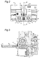
- a rotating drive 13 (see also Fig. 3 ), consisting of a rotationally driven part 14 and a stationary sleeve 15 surrounding it, is present between the gripping finger sockets 9 and 10.
- Rotationally driven part 14 is made to rotate, either to the left or to the right, by a servomotor 42 with worm 41 and in this case at least one of the directions of rotation is torque-driven, that is to say the maximum force of rotation which is applied can be controlled by means of software.
- Sleeve 15 can be moved to and fro in the direction of the rotation axis 18. By way of example, a value of 15 mm is given for the stroke for the sleeve which can be moved in translation.
- This movement is a pneumatically controlled movement which may be achieved by a piston-cylinder (not shown) (in which sleeve 15 may be part of the piston) present in the housing 6 and the associated control unit.
- Sleeve 15 is designed to hold different kinds of tools and at reference numeral 16 an example thereof is shown.
- a click-fit connection By means of a click-fit connection, the tool 16 can be held in the sleeve 15 and be rotationally driven via corresponding toothing.
- a click-fit connection By gripping the tool 16 at the free end and moving the gripping device (or sleeve 15) away, such a click-fit connection can be released again in a simple manner.
- Such gripping may, for example, include attaching the tool behind any construction.
- a fluid such as air
- air pressure produces an additional spring action in addition to that of the sleeve 15, as a result of which, for example, tool 16 can resiliently be pushed against a bolt head. At low rotation, the tool subsequently grabs the respective bolt head. The same applies to the return movement of the tool, where active withdrawal takes place.
- the resilient action makes it possible to push an object against another object using a certain pneumatically controlled resilience.
- gripping fingers 17 are shown which can be placed into the openings 26 of the gripping finger sockets 10.
- the ends of the gripping fingers 17 are designed to cooperate with a coupling 12 behind the opening 26 in each of the gripping finger sockets.
- the illustrated example shows a construction with a cone in which such a cone can be fixed on the end of the gripping fingers 17 in a single fixed non-rotatable position by means of pins 28 in the gripping finger sockets.
- pins 28 can be actuated electrically or pneumatically.
- the control unit for the various functions is denoted by reference numeral 21 and not shown in any more detail.
- a vision system consisting of a camera 19 and a laser 49 is present.
- the camera is preferably a 2D camera which, in combination with the laser, forms a 3D system.
- the software which this requires is preferably stored externally (PC).
- PC externally
- Fig. 2 shows the completely closed position of the two gripping finger sockets, that is to say the position in which they abut.
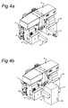
- Figs. 4a and b show the clamping of an object 30. To this end, specifically designed gripping fingers 17 are used.
- Fig. 5 shows a variant in which different gripping fingers 27 are used.
- Changing the gripping fingers can be effected in a simple manner by moving the gripping device with the gripping fingers to a storage position in which a displacement direction of the gripping fingers is blocked (by hooking, latching and the like). By then releasing the coupling 12, the respective gripping finger can be released and another gripping finger can be positioned.
- the construction is such that the gripping finger can only be positioned in one position with respect to the socket and it is possible to achieve a particularly high degree of accuracy with the present invention, so that the gripping finger is fixed only in a position with an accuracy of hundredths of millimetres with respect to the gripping finger socket.
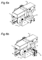
- Figs. 6a, b show how an object 31 is clamped, in which a bolt or the like has to be screwed down by means of the tool 16.
- the tool 16 When approaching the respective object, the tool 16 is held in a position in which it is as much as possible inside the housing 6, as a result of which the gripping fingers are free to clamp the object 31.
- the tool 16 which can be moved in translation can be moved out in order to carry out the respective tightening or loosening.
- the tool 16 is pneumatically pushed against the bolt head or the like and, after a few rotations around the bolt head, falls into a cavity. Since the resistance against rotation then quickly increases, the servomotor for the rotation of the bolt detects that engagement has taken place and the desired torque can be applied. During unscrewing, the displacement of the sleeve creates the necessary free space.
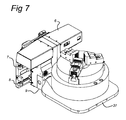
- Fig. 7 shows a pallet 37 which is provided with two coupling parts (not clearly visible) which match the gripping fingers.
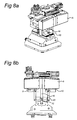
- Fig. 8 shows the gripping of the gripping jaws 20. These can be placed in the desired position by the gripping fingers in which case it is moreover possible, if an object to be clamped is present, to pretension the gripping jaws towards one another using the gripping fingers into a discrete position which is determined, for example by toothing.
- Fig. 9 shows the clamping of an object by means of a clamping element 24 and bolt 25.
- a clamping element 24 and bolt 25 it is possible to achieve such a clamping by means of the universal gripping device according to the present invention without many other measures. Only the gripping fingers and/or the tool have to be adjusted in such a case.
- the gripping device By means of the gripping device according to the present invention, it is possible to grip many kinds of objects and clamp and/or position them at the desired pretension and to then fix or release them by means of the rotating drive. Using the invention, it is possible to place relatively heavy objects without a defined position with a high degree of accuracy.
- the weight of the gripping device itself is relatively low and by way of example, a weight of less than 35 kilos is mentioned.
Landscapes
- Engineering & Computer Science (AREA)
- Robotics (AREA)
- Mechanical Engineering (AREA)
- Manipulator (AREA)
Claims (11)
- Greifvorrichtung (4), welche ein Gehäuse (6) aufweist, wobei das Gehäuse (6) eine Verbindung (5) aufweist zum Befestigen des Gehäuses (6) an einen Roboterarm (2), wobei das Gehäuse zwei Greiffinger-Aufnahmen (9, 10) aufweist, die in Bezug zum Gehäuse und in Bezug zueinander in einer kontrollierten Art und Weise versetzt werden können, wobei Greiffinger (17, 27, 37) in jedem der Greiffinger-Aufnahmen (9, 10) vorgesehen sind und wobei die Greifvorrichtung (4) einen rotierenden Antrieb (13) aufweist, welcher in das Gehäuse (6) eingepasst ist, wobei der rotierende Antrieb ein Kopplungsteil (15) aufweist, welches translatorisch in Richtung der Rotationsachse (18) des rotierenden Antriebs beweglich ist und zur Verbindung mit verschiedenen Werkzeugen ausgelegt ist, durch welche verschiedene Befestigungsmittel befestigt oder gelöst werden können, und wobei die Greiffinger-Aufnahmen eine pneumatische, elektrische oder hydraulische Kopplung aufweisen um die Greiffinger arretieren oder freigeben zu können, wobei die Greiffinger in Bezug auf die Greiffinger-Aufnahmen ersetzbar und in einer festgelegten Position verbindbar sind.
- Greifvorrichtung nach einem der vorhergehenden Ansprüche, in welcher das Kupplungsteil (15) zwischen den Greiffingem (17, 27, 37) angeordnet ist.
- Greifvorrichtung nach einem der vorhergehenden Ansprüche, in welcher das Gehäuse eine lineare Führung (7, 8) für die Greiffinger-Aufnahmen aufweist.
- Greifvorrichtung nach einem der vorgehergehenden Ansprüche, in welcher der rotierende Antrieb (13) ein selbstverschließendes (41) Design aufweist.
- Greifvorrichtung nach einem der vorhergehenden Ansprüche, in welcher die Greiffinger-Aufnahmen und der restliche Teil der Vorrichtung für Lasten von zumindest 150 kg ausgelegt sind.
- Greifvorrichtung nach einem der vorhergehenden Ansprüche, in welcher das Gehäuse zum Finden und zur Annäherung an Objekte ein 3-D-Sichtsystem und eine Steuereinheit aufweist.
- Greifvorrichtung nach einem der vorhergehenden Ansprüche, in welcher die Greiffinger durch einen gewöhnlichen Servomotor (43) angetrieben werden.
- Greifvorrichtung nach einem der vorhergehenden Ansprüche, wobei die Greiffinger-Aufnahmen in Bezug auf die Position, Kraft und / oder Geschwindigkeit kontrolliert versetzbar sind.
- Greifvorrichtung nach Anspruch 8, wobei die Greiffinger-Aufnahmen durch einen Servomotor versetzbar sind.
- Zusammenstellung, welches eine Vorrichtung nach einem der vorhergehenden Ansprüche und einen Roboterarm (2) aufweist, wobei in der Zusammenstellung die Vorrichtung (4) an dem Roboterarm befestigt ist.
- Verfahren zum Befestigen eines Objekts in Bezug zu einem weiteren Objekt, wobei das Objekt rotierende Befestigungsmittel aufweist, wobei das Objekt mit den Greiffingem (17, 27, 37) mit Hilfe der Zusammenstellung nach Anspruch 10 ergriffen wird, wobei das Objekt in Bezug auf das weitere Objekt positioniert wird, wobei das Objekt in der gewünschten Position mit Hilfe des rotierenden Antriebs (13) der Greifvorrichtung fixiert wird, und wobei darauffolgend die Greiffinger von dem Objekt wegbewegt werden.
Applications Claiming Priority (2)
| Application Number | Priority Date | Filing Date | Title |
|---|---|---|---|
| NL2004830A NL2004830C2 (nl) | 2010-06-07 | 2010-06-07 | Grijpinrichting. |
| PCT/NL2011/050403 WO2011155826A1 (en) | 2010-06-07 | 2011-06-07 | Gripping device |
Publications (2)
| Publication Number | Publication Date |
|---|---|
| EP2576158A1 EP2576158A1 (de) | 2013-04-10 |
| EP2576158B1 true EP2576158B1 (de) | 2014-04-30 |
Family
ID=43012172
Family Applications (1)
| Application Number | Title | Priority Date | Filing Date |
|---|---|---|---|
| EP11726211.3A Not-in-force EP2576158B1 (de) | 2010-06-07 | 2011-06-07 | Greifvorrichtung |
Country Status (5)
| Country | Link |
|---|---|
| US (1) | US8939487B2 (de) |
| EP (1) | EP2576158B1 (de) |
| JP (1) | JP2013528125A (de) |
| NL (1) | NL2004830C2 (de) |
| WO (1) | WO2011155826A1 (de) |
Cited By (1)
| Publication number | Priority date | Publication date | Assignee | Title |
|---|---|---|---|---|
| DE102024003550A1 (de) * | 2024-10-25 | 2026-04-30 | Michael Weinig Aktiengesellschaft | Werkzeugwechsel-Vorrichtung, Kehlmaschine mit einer Werkzeugwechsel-Vorrichtung, Verwendung eines Mehrachs-Roboters zum Wechseln von Werkzeugen einer Kehlmaschine und Verfahren zum Einwechseln/Herausnehmen eines Werkzeuges in/aus einer Bearbeitungsspindel |
Families Citing this family (18)
| Publication number | Priority date | Publication date | Assignee | Title |
|---|---|---|---|---|
| KR20160004304A (ko) * | 2013-04-29 | 2016-01-12 | 레클루즈 모터 스포츠, 아이엔씨. | 로봇 텐딩을 사용한 다양한 부품 형상 저장과 처리를 위한 시스템 및 방법 |
| CN104440932B (zh) * | 2014-11-28 | 2015-11-11 | 金石机器人常州有限公司 | 伺服驱动的具有浮动功能的组合抓手 |
| US9401300B1 (en) * | 2014-12-18 | 2016-07-26 | WD Media, LLC | Media substrate gripper including a plurality of snap-fit fingers |
| US9855663B1 (en) * | 2016-06-17 | 2018-01-02 | X Development Llc | Automated digit interchange |
| CN106625727A (zh) * | 2016-10-31 | 2017-05-10 | 湖北工业大学 | 一种图书抓取与放回装置的末端执行器 |
| JP6363752B1 (ja) * | 2017-03-13 | 2018-07-25 | 上銀科技股▲フン▼有限公司 | 把持装置 |
| KR102451713B1 (ko) * | 2017-12-11 | 2022-10-05 | 삼성전자주식회사 | 그리퍼 |
| CN108608446B (zh) * | 2018-04-28 | 2024-05-28 | 上海发那科机器人有限公司 | 一种油泵壳机加工搬运机器人三手爪装置 |
| KR102474383B1 (ko) * | 2018-07-10 | 2022-12-05 | 현대자동차 주식회사 | 로봇 그리퍼 |
| US12145246B1 (en) | 2019-04-12 | 2024-11-19 | Kurt Manufacturing Company, Inc. | Workpiece processing system |
| US11141865B1 (en) | 2019-08-15 | 2021-10-12 | Design Ready Controls, Inc. | Robot gripper assembly |
| LV15561A (lv) * | 2019-10-03 | 2021-04-20 | Roboeatz, Sia | Robotizēta ēdienu pagatavošanas sistēma |
| CN110802624B (zh) * | 2019-11-22 | 2020-11-13 | 合肥常青机械股份有限公司 | 一种抓手可更换型机器手臂 |
| US11305436B2 (en) * | 2020-02-24 | 2022-04-19 | Tctm (Hong Kong) Limited | Lateral gripper |
| CN111993405A (zh) * | 2020-08-27 | 2020-11-27 | 马鞍山贺辉信息科技有限公司 | 一种工业智能机器人的抓取设备及其抓取方法 |
| US20220193934A1 (en) * | 2020-12-23 | 2022-06-23 | Delaware Capital Formation, Inc. | Gripper Jaw Sensor |
| US20220234215A1 (en) * | 2021-01-28 | 2022-07-28 | Ford Global Technologies, Llc | Integrated robotic end effectors having end of arm tool grippers |
| CN113021301B (zh) * | 2021-04-20 | 2023-04-18 | 深圳市博洋精密科技有限公司 | 基于四轴机器人的网格状搬运系统 |
Family Cites Families (13)
| Publication number | Priority date | Publication date | Assignee | Title |
|---|---|---|---|---|
| US3139302A (en) * | 1961-09-08 | 1964-06-30 | Molins Machine Co Ltd | Mechanical handling apparatus |
| US4042122A (en) * | 1975-05-27 | 1977-08-16 | The Bendix Corporation | Reorientation device for an object manipulator |
| US4819978A (en) * | 1986-06-27 | 1989-04-11 | California Institute Of Technology | Grasp force sensor for robotic hands |
| JPH0392712A (ja) * | 1989-09-05 | 1991-04-17 | Fanuc Ltd | 画像処理装置と測距センサによる物体の3次元位置認識方法 |
| JP2661767B2 (ja) * | 1990-04-12 | 1997-10-08 | キヤノン株式会社 | フインガ交換方法及びハンド装置 |
| US5184861A (en) * | 1991-02-15 | 1993-02-09 | The United States Of America As Represented By The Administrator, National Aeronautics & Space Administration | Split rail gripper assembly and tool driver therefor |
| US5163729A (en) * | 1991-08-22 | 1992-11-17 | Nicky Borcea | Parallel gripper assembly |
| US5360249A (en) * | 1991-09-13 | 1994-11-01 | Refac Technology Development, Corporation | Multifunctional end effectors |
| US5562320A (en) * | 1994-11-04 | 1996-10-08 | International Business Machines Corporation | Gripper head |
| JPH08309626A (ja) * | 1995-05-15 | 1996-11-26 | Daifuku Co Ltd | ネジ締め装置 |
| JP3400229B2 (ja) * | 1996-02-29 | 2003-04-28 | 川崎製鉄株式会社 | 穿孔プラグの着脱装置 |
| DE102005058312A1 (de) * | 2005-12-07 | 2007-06-14 | Dürr Ecoclean GmbH | Greifvorrichtung für einen Roboter oder einen Portallader |
| DE102006052902B4 (de) * | 2006-11-08 | 2016-03-03 | Deutsches Zentrum für Luft- und Raumfahrt e.V. | Radmontage-Industrieroboter, Endeffektor und Verfahren zur Montage eines Rades durch einen Radmontage-Industrieroboter |
-
2010
- 2010-06-07 NL NL2004830A patent/NL2004830C2/nl not_active IP Right Cessation
-
2011
- 2011-06-07 US US13/702,856 patent/US8939487B2/en not_active Expired - Fee Related
- 2011-06-07 WO PCT/NL2011/050403 patent/WO2011155826A1/en not_active Ceased
- 2011-06-07 JP JP2013514128A patent/JP2013528125A/ja active Pending
- 2011-06-07 EP EP11726211.3A patent/EP2576158B1/de not_active Not-in-force
Cited By (1)
| Publication number | Priority date | Publication date | Assignee | Title |
|---|---|---|---|---|
| DE102024003550A1 (de) * | 2024-10-25 | 2026-04-30 | Michael Weinig Aktiengesellschaft | Werkzeugwechsel-Vorrichtung, Kehlmaschine mit einer Werkzeugwechsel-Vorrichtung, Verwendung eines Mehrachs-Roboters zum Wechseln von Werkzeugen einer Kehlmaschine und Verfahren zum Einwechseln/Herausnehmen eines Werkzeuges in/aus einer Bearbeitungsspindel |
Also Published As
| Publication number | Publication date |
|---|---|
| EP2576158A1 (de) | 2013-04-10 |
| WO2011155826A1 (en) | 2011-12-15 |
| NL2004830C2 (nl) | 2011-12-08 |
| US8939487B2 (en) | 2015-01-27 |
| US20130154293A1 (en) | 2013-06-20 |
| JP2013528125A (ja) | 2013-07-08 |
Similar Documents
| Publication | Publication Date | Title |
|---|---|---|
| US8939487B2 (en) | Gripping device | |
| CN108500964B (zh) | 端部效应器组件和具有端部效应器组件的机器人系统 | |
| US6772493B2 (en) | Workpiece changing system | |
| US4922436A (en) | Method and system for the automated driving of parts and device used therein | |
| EP3197644B1 (de) | Automatisch positionierbare gelenke und übertragungswerkzeuganordnung mit automatisch positionierbaren gelenken | |
| EP2995402B1 (de) | Vorrichtung und verfahren zur verarbeitung eines begrenzten abschnitts eines werkstücks | |
| CN104308859B (zh) | 基于行车的重载精密冗余三臂机械手 | |
| US10011021B2 (en) | Gripping jaw safety device with tongue and groove for HRC | |
| KR102060867B1 (ko) | O링 부착 장치 및 방법 | |
| EP3003647B1 (de) | Crimpkopf für schlagschrauber | |
| CN204076281U (zh) | 基于行车的重载精密冗余三臂机械手 | |
| US5184861A (en) | Split rail gripper assembly and tool driver therefor | |
| US4615101A (en) | Tool interface for robot end effectors | |
| EP3162507B1 (de) | Magnetschwebeschraubenklemmbacke für automatische schraubendreher | |
| EP2714342A1 (de) | Konfigurierbares handhabungswerkzeugsystem | |
| CN104128927A (zh) | 一种机器人抓取装置 | |
| WO2015155300A1 (de) | Roboterarbeitsplatz | |
| EP3315251B1 (de) | Elektrospindel für automatischen werkzeugwechsel und bearbeitungszentrum mit automatischer werkzeugwechselvorrichtung | |
| US20170151677A1 (en) | Plug-Setting Device | |
| EP3037190B1 (de) | Greifvorrichtung für Befestigungselemente | |
| CN107571072A (zh) | 夹紧单元 | |
| JP7676438B2 (ja) | 把持用工具、システムおよび挟持用工具、交換ステーションおよび該システムまたは挟持用工具を用いて物体をハンドリングする方法 | |
| US4550922A (en) | Workholder | |
| KR20180008746A (ko) | 전기 기기 부착 장치 및 방법 | |
| US20170216983A1 (en) | Workpiece clamping device, and processing system having workpiece clamping device |
Legal Events
| Date | Code | Title | Description |
|---|---|---|---|
| PUAI | Public reference made under article 153(3) epc to a published international application that has entered the european phase |
Free format text: ORIGINAL CODE: 0009012 |
|
| 17P | Request for examination filed |
Effective date: 20130104 |
|
| AK | Designated contracting states |
Kind code of ref document: A1 Designated state(s): AL AT BE BG CH CY CZ DE DK EE ES FI FR GB GR HR HU IE IS IT LI LT LU LV MC MK MT NL NO PL PT RO RS SE SI SK SM TR |
|
| DAX | Request for extension of the european patent (deleted) | ||
| GRAP | Despatch of communication of intention to grant a patent |
Free format text: ORIGINAL CODE: EPIDOSNIGR1 |
|
| RIC1 | Information provided on ipc code assigned before grant |
Ipc: B25J 15/02 20060101AFI20131009BHEP Ipc: B25J 15/04 20060101ALI20131009BHEP Ipc: B25J 15/00 20060101ALI20131009BHEP |
|
| INTG | Intention to grant announced |
Effective date: 20131111 |
|
| GRAS | Grant fee paid |
Free format text: ORIGINAL CODE: EPIDOSNIGR3 |
|
| GRAA | (expected) grant |
Free format text: ORIGINAL CODE: 0009210 |
|
| AK | Designated contracting states |
Kind code of ref document: B1 Designated state(s): AL AT BE BG CH CY CZ DE DK EE ES FI FR GB GR HR HU IE IS IT LI LT LU LV MC MK MT NL NO PL PT RO RS SE SI SK SM TR |
|
| REG | Reference to a national code |
Ref country code: GB Ref legal event code: FG4D Ref country code: CH Ref legal event code: EP |
|
| REG | Reference to a national code |
Ref country code: AT Ref legal event code: REF Ref document number: 664784 Country of ref document: AT Kind code of ref document: T Effective date: 20140515 |
|
| REG | Reference to a national code |
Ref country code: IE Ref legal event code: FG4D |
|
| REG | Reference to a national code |
Ref country code: DE Ref legal event code: R096 Ref document number: 602011006587 Country of ref document: DE Effective date: 20140612 |
|
| REG | Reference to a national code |
Ref country code: CH Ref legal event code: NV Representative=s name: FIAMMENGHI-FIAMMENGHI, CH |
|
| REG | Reference to a national code |
Ref country code: SE Ref legal event code: TRGR |
|
| REG | Reference to a national code |
Ref country code: NL Ref legal event code: T3 |
|
| REG | Reference to a national code |
Ref country code: AT Ref legal event code: MK05 Ref document number: 664784 Country of ref document: AT Kind code of ref document: T Effective date: 20140430 |
|
| REG | Reference to a national code |
Ref country code: LT Ref legal event code: MG4D |
|
| PG25 | Lapsed in a contracting state [announced via postgrant information from national office to epo] |
Ref country code: NO Free format text: LAPSE BECAUSE OF FAILURE TO SUBMIT A TRANSLATION OF THE DESCRIPTION OR TO PAY THE FEE WITHIN THE PRESCRIBED TIME-LIMIT Effective date: 20140730 Ref country code: LT Free format text: LAPSE BECAUSE OF FAILURE TO SUBMIT A TRANSLATION OF THE DESCRIPTION OR TO PAY THE FEE WITHIN THE PRESCRIBED TIME-LIMIT Effective date: 20140430 Ref country code: FI Free format text: LAPSE BECAUSE OF FAILURE TO SUBMIT A TRANSLATION OF THE DESCRIPTION OR TO PAY THE FEE WITHIN THE PRESCRIBED TIME-LIMIT Effective date: 20140430 Ref country code: IS Free format text: LAPSE BECAUSE OF FAILURE TO SUBMIT A TRANSLATION OF THE DESCRIPTION OR TO PAY THE FEE WITHIN THE PRESCRIBED TIME-LIMIT Effective date: 20140830 Ref country code: CY Free format text: LAPSE BECAUSE OF FAILURE TO SUBMIT A TRANSLATION OF THE DESCRIPTION OR TO PAY THE FEE WITHIN THE PRESCRIBED TIME-LIMIT Effective date: 20140430 Ref country code: GR Free format text: LAPSE BECAUSE OF FAILURE TO SUBMIT A TRANSLATION OF THE DESCRIPTION OR TO PAY THE FEE WITHIN THE PRESCRIBED TIME-LIMIT Effective date: 20140731 Ref country code: BG Free format text: LAPSE BECAUSE OF FAILURE TO SUBMIT A TRANSLATION OF THE DESCRIPTION OR TO PAY THE FEE WITHIN THE PRESCRIBED TIME-LIMIT Effective date: 20140730 |
|
| PG25 | Lapsed in a contracting state [announced via postgrant information from national office to epo] |
Ref country code: AT Free format text: LAPSE BECAUSE OF FAILURE TO SUBMIT A TRANSLATION OF THE DESCRIPTION OR TO PAY THE FEE WITHIN THE PRESCRIBED TIME-LIMIT Effective date: 20140430 Ref country code: ES Free format text: LAPSE BECAUSE OF FAILURE TO SUBMIT A TRANSLATION OF THE DESCRIPTION OR TO PAY THE FEE WITHIN THE PRESCRIBED TIME-LIMIT Effective date: 20140430 Ref country code: RS Free format text: LAPSE BECAUSE OF FAILURE TO SUBMIT A TRANSLATION OF THE DESCRIPTION OR TO PAY THE FEE WITHIN THE PRESCRIBED TIME-LIMIT Effective date: 20140430 Ref country code: LV Free format text: LAPSE BECAUSE OF FAILURE TO SUBMIT A TRANSLATION OF THE DESCRIPTION OR TO PAY THE FEE WITHIN THE PRESCRIBED TIME-LIMIT Effective date: 20140430 Ref country code: HR Free format text: LAPSE BECAUSE OF FAILURE TO SUBMIT A TRANSLATION OF THE DESCRIPTION OR TO PAY THE FEE WITHIN THE PRESCRIBED TIME-LIMIT Effective date: 20140430 Ref country code: PL Free format text: LAPSE BECAUSE OF FAILURE TO SUBMIT A TRANSLATION OF THE DESCRIPTION OR TO PAY THE FEE WITHIN THE PRESCRIBED TIME-LIMIT Effective date: 20140430 |
|
| PG25 | Lapsed in a contracting state [announced via postgrant information from national office to epo] |
Ref country code: PT Free format text: LAPSE BECAUSE OF FAILURE TO SUBMIT A TRANSLATION OF THE DESCRIPTION OR TO PAY THE FEE WITHIN THE PRESCRIBED TIME-LIMIT Effective date: 20140901 |
|
| PG25 | Lapsed in a contracting state [announced via postgrant information from national office to epo] |
Ref country code: SK Free format text: LAPSE BECAUSE OF FAILURE TO SUBMIT A TRANSLATION OF THE DESCRIPTION OR TO PAY THE FEE WITHIN THE PRESCRIBED TIME-LIMIT Effective date: 20140430 Ref country code: EE Free format text: LAPSE BECAUSE OF FAILURE TO SUBMIT A TRANSLATION OF THE DESCRIPTION OR TO PAY THE FEE WITHIN THE PRESCRIBED TIME-LIMIT Effective date: 20140430 Ref country code: MC Free format text: LAPSE BECAUSE OF FAILURE TO SUBMIT A TRANSLATION OF THE DESCRIPTION OR TO PAY THE FEE WITHIN THE PRESCRIBED TIME-LIMIT Effective date: 20140430 Ref country code: CZ Free format text: LAPSE BECAUSE OF FAILURE TO SUBMIT A TRANSLATION OF THE DESCRIPTION OR TO PAY THE FEE WITHIN THE PRESCRIBED TIME-LIMIT Effective date: 20140430 Ref country code: BE Free format text: LAPSE BECAUSE OF FAILURE TO SUBMIT A TRANSLATION OF THE DESCRIPTION OR TO PAY THE FEE WITHIN THE PRESCRIBED TIME-LIMIT Effective date: 20140430 Ref country code: RO Free format text: LAPSE BECAUSE OF FAILURE TO SUBMIT A TRANSLATION OF THE DESCRIPTION OR TO PAY THE FEE WITHIN THE PRESCRIBED TIME-LIMIT Effective date: 20140430 Ref country code: DK Free format text: LAPSE BECAUSE OF FAILURE TO SUBMIT A TRANSLATION OF THE DESCRIPTION OR TO PAY THE FEE WITHIN THE PRESCRIBED TIME-LIMIT Effective date: 20140430 |
|
| REG | Reference to a national code |
Ref country code: CH Ref legal event code: PL Ref country code: CH Ref legal event code: AECN Free format text: DAS PATENT IST AUFGRUND DES WEITERBEHANDLUNGSANTRAGS VOM 19. JANUAR 2015 REAKTIVIERT WORDEN. |
|
| REG | Reference to a national code |
Ref country code: DE Ref legal event code: R097 Ref document number: 602011006587 Country of ref document: DE |
|
| PLBE | No opposition filed within time limit |
Free format text: ORIGINAL CODE: 0009261 |
|
| STAA | Information on the status of an ep patent application or granted ep patent |
Free format text: STATUS: NO OPPOSITION FILED WITHIN TIME LIMIT |
|
| REG | Reference to a national code |
Ref country code: IE Ref legal event code: MM4A |
|
| 26N | No opposition filed |
Effective date: 20150202 |
|
| PG25 | Lapsed in a contracting state [announced via postgrant information from national office to epo] |
Ref country code: IE Free format text: LAPSE BECAUSE OF NON-PAYMENT OF DUE FEES Effective date: 20140607 |
|
| REG | Reference to a national code |
Ref country code: DE Ref legal event code: R097 Ref document number: 602011006587 Country of ref document: DE Effective date: 20150202 |
|
| PG25 | Lapsed in a contracting state [announced via postgrant information from national office to epo] |
Ref country code: SI Free format text: LAPSE BECAUSE OF FAILURE TO SUBMIT A TRANSLATION OF THE DESCRIPTION OR TO PAY THE FEE WITHIN THE PRESCRIBED TIME-LIMIT Effective date: 20140430 |
|
| PGFP | Annual fee paid to national office [announced via postgrant information from national office to epo] |
Ref country code: LU Payment date: 20150625 Year of fee payment: 5 |
|
| PGFP | Annual fee paid to national office [announced via postgrant information from national office to epo] |
Ref country code: SE Payment date: 20150630 Year of fee payment: 5 |
|
| PG25 | Lapsed in a contracting state [announced via postgrant information from national office to epo] |
Ref country code: MT Free format text: LAPSE BECAUSE OF FAILURE TO SUBMIT A TRANSLATION OF THE DESCRIPTION OR TO PAY THE FEE WITHIN THE PRESCRIBED TIME-LIMIT Effective date: 20140430 |
|
| PG25 | Lapsed in a contracting state [announced via postgrant information from national office to epo] |
Ref country code: SM Free format text: LAPSE BECAUSE OF FAILURE TO SUBMIT A TRANSLATION OF THE DESCRIPTION OR TO PAY THE FEE WITHIN THE PRESCRIBED TIME-LIMIT Effective date: 20140430 |
|
| REG | Reference to a national code |
Ref country code: FR Ref legal event code: PLFP Year of fee payment: 6 |
|
| PG25 | Lapsed in a contracting state [announced via postgrant information from national office to epo] |
Ref country code: HU Free format text: LAPSE BECAUSE OF FAILURE TO SUBMIT A TRANSLATION OF THE DESCRIPTION OR TO PAY THE FEE WITHIN THE PRESCRIBED TIME-LIMIT; INVALID AB INITIO Effective date: 20110607 Ref country code: TR Free format text: LAPSE BECAUSE OF FAILURE TO SUBMIT A TRANSLATION OF THE DESCRIPTION OR TO PAY THE FEE WITHIN THE PRESCRIBED TIME-LIMIT Effective date: 20140430 |
|
| PG25 | Lapsed in a contracting state [announced via postgrant information from national office to epo] |
Ref country code: LU Free format text: LAPSE BECAUSE OF NON-PAYMENT OF DUE FEES Effective date: 20160607 |
|
| REG | Reference to a national code |
Ref country code: SE Ref legal event code: EUG |
|
| PG25 | Lapsed in a contracting state [announced via postgrant information from national office to epo] |
Ref country code: SE Free format text: LAPSE BECAUSE OF NON-PAYMENT OF DUE FEES Effective date: 20160608 |
|
| REG | Reference to a national code |
Ref country code: FR Ref legal event code: PLFP Year of fee payment: 7 |
|
| PGFP | Annual fee paid to national office [announced via postgrant information from national office to epo] |
Ref country code: NL Payment date: 20170426 Year of fee payment: 7 |
|
| PGFP | Annual fee paid to national office [announced via postgrant information from national office to epo] |
Ref country code: FR Payment date: 20170629 Year of fee payment: 7 Ref country code: GB Payment date: 20170630 Year of fee payment: 7 Ref country code: CH Payment date: 20170627 Year of fee payment: 7 |
|
| PGFP | Annual fee paid to national office [announced via postgrant information from national office to epo] |
Ref country code: IT Payment date: 20170623 Year of fee payment: 7 |
|
| PGFP | Annual fee paid to national office [announced via postgrant information from national office to epo] |
Ref country code: DE Payment date: 20170831 Year of fee payment: 7 |
|
| PG25 | Lapsed in a contracting state [announced via postgrant information from national office to epo] |
Ref country code: MK Free format text: LAPSE BECAUSE OF FAILURE TO SUBMIT A TRANSLATION OF THE DESCRIPTION OR TO PAY THE FEE WITHIN THE PRESCRIBED TIME-LIMIT Effective date: 20140430 |
|
| PG25 | Lapsed in a contracting state [announced via postgrant information from national office to epo] |
Ref country code: AL Free format text: LAPSE BECAUSE OF FAILURE TO SUBMIT A TRANSLATION OF THE DESCRIPTION OR TO PAY THE FEE WITHIN THE PRESCRIBED TIME-LIMIT Effective date: 20140430 |
|
| REG | Reference to a national code |
Ref country code: DE Ref legal event code: R119 Ref document number: 602011006587 Country of ref document: DE |
|
| REG | Reference to a national code |
Ref country code: CH Ref legal event code: PL |
|
| REG | Reference to a national code |
Ref country code: NL Ref legal event code: MM Effective date: 20180701 |
|
| GBPC | Gb: european patent ceased through non-payment of renewal fee |
Effective date: 20180607 |
|
| PG25 | Lapsed in a contracting state [announced via postgrant information from national office to epo] |
Ref country code: NL Free format text: LAPSE BECAUSE OF NON-PAYMENT OF DUE FEES Effective date: 20180701 |
|
| PG25 | Lapsed in a contracting state [announced via postgrant information from national office to epo] |
Ref country code: LI Free format text: LAPSE BECAUSE OF NON-PAYMENT OF DUE FEES Effective date: 20180630 Ref country code: FR Free format text: LAPSE BECAUSE OF NON-PAYMENT OF DUE FEES Effective date: 20180630 Ref country code: GB Free format text: LAPSE BECAUSE OF NON-PAYMENT OF DUE FEES Effective date: 20180607 Ref country code: CH Free format text: LAPSE BECAUSE OF NON-PAYMENT OF DUE FEES Effective date: 20180630 Ref country code: DE Free format text: LAPSE BECAUSE OF NON-PAYMENT OF DUE FEES Effective date: 20190101 Ref country code: IT Free format text: LAPSE BECAUSE OF NON-PAYMENT OF DUE FEES Effective date: 20180607 |