EP2575249B1 - Transformateur à décalage de phase dans un onduleur de tension moyenne à plusieurs niveaux - Google Patents
Transformateur à décalage de phase dans un onduleur de tension moyenne à plusieurs niveaux Download PDFInfo
- Publication number
- EP2575249B1 EP2575249B1 EP12180533.7A EP12180533A EP2575249B1 EP 2575249 B1 EP2575249 B1 EP 2575249B1 EP 12180533 A EP12180533 A EP 12180533A EP 2575249 B1 EP2575249 B1 EP 2575249B1
- Authority
- EP
- European Patent Office
- Prior art keywords
- phase shift
- phase
- module
- shift transformer
- power
- Prior art date
- Legal status (The legal status is an assumption and is not a legal conclusion. Google has not performed a legal analysis and makes no representation as to the accuracy of the status listed.)
- Active
Links
- 230000010363 phase shift Effects 0.000 title claims description 111
- 238000004804 winding Methods 0.000 claims description 77
- 239000003990 capacitor Substances 0.000 description 6
- 230000000295 complement effect Effects 0.000 description 2
- 238000010276 construction Methods 0.000 description 2
- 229930091051 Arenine Natural products 0.000 description 1
- 241000282320 Panthera leo Species 0.000 description 1
- 239000000470 constituent Substances 0.000 description 1
- 230000000694 effects Effects 0.000 description 1
- 238000002955 isolation Methods 0.000 description 1
- 238000000034 method Methods 0.000 description 1
Images





Classifications
-
- H—ELECTRICITY
- H01—ELECTRIC ELEMENTS
- H01F—MAGNETS; INDUCTANCES; TRANSFORMERS; SELECTION OF MATERIALS FOR THEIR MAGNETIC PROPERTIES
- H01F30/00—Fixed transformers not covered by group H01F19/00
- H01F30/06—Fixed transformers not covered by group H01F19/00 characterised by the structure
- H01F30/12—Two-phase, three-phase or polyphase transformers
-
- H—ELECTRICITY
- H02—GENERATION; CONVERSION OR DISTRIBUTION OF ELECTRIC POWER
- H02M—APPARATUS FOR CONVERSION BETWEEN AC AND AC, BETWEEN AC AND DC, OR BETWEEN DC AND DC, AND FOR USE WITH MAINS OR SIMILAR POWER SUPPLY SYSTEMS; CONVERSION OF DC OR AC INPUT POWER INTO SURGE OUTPUT POWER; CONTROL OR REGULATION THEREOF
- H02M5/00—Conversion of AC power input into AC power output, e.g. for change of voltage, for change of frequency, for change of number of phases
- H02M5/40—Conversion of AC power input into AC power output, e.g. for change of voltage, for change of frequency, for change of number of phases with intermediate conversion into DC
- H02M5/42—Conversion of AC power input into AC power output, e.g. for change of voltage, for change of frequency, for change of number of phases with intermediate conversion into DC by static converters
-
- H—ELECTRICITY
- H02—GENERATION; CONVERSION OR DISTRIBUTION OF ELECTRIC POWER
- H02M—APPARATUS FOR CONVERSION BETWEEN AC AND AC, BETWEEN AC AND DC, OR BETWEEN DC AND DC, AND FOR USE WITH MAINS OR SIMILAR POWER SUPPLY SYSTEMS; CONVERSION OF DC OR AC INPUT POWER INTO SURGE OUTPUT POWER; CONTROL OR REGULATION THEREOF
- H02M7/00—Conversion of AC power input into DC power output; Conversion of DC power input into AC power output
- H02M7/42—Conversion of DC power input into AC power output without possibility of reversal
- H02M7/44—Conversion of DC power input into AC power output without possibility of reversal by static converters
- H02M7/48—Conversion of DC power input into AC power output without possibility of reversal by static converters using discharge tubes with control electrode or semiconductor devices with control electrode
- H02M7/483—Converters with outputs that each can have more than two voltages levels
- H02M7/487—Neutral point clamped inverters
-
- H—ELECTRICITY
- H02—GENERATION; CONVERSION OR DISTRIBUTION OF ELECTRIC POWER
- H02M—APPARATUS FOR CONVERSION BETWEEN AC AND AC, BETWEEN AC AND DC, OR BETWEEN DC AND DC, AND FOR USE WITH MAINS OR SIMILAR POWER SUPPLY SYSTEMS; CONVERSION OF DC OR AC INPUT POWER INTO SURGE OUTPUT POWER; CONTROL OR REGULATION THEREOF
- H02M7/00—Conversion of AC power input into DC power output; Conversion of DC power input into AC power output
- H02M7/42—Conversion of DC power input into AC power output without possibility of reversal
- H02M7/44—Conversion of DC power input into AC power output without possibility of reversal by static converters
- H02M7/48—Conversion of DC power input into AC power output without possibility of reversal by static converters using discharge tubes with control electrode or semiconductor devices with control electrode
- H02M7/483—Converters with outputs that each can have more than two voltages levels
- H02M7/49—Combination of the output voltage waveforms of a plurality of converters
-
- H—ELECTRICITY
- H02—GENERATION; CONVERSION OR DISTRIBUTION OF ELECTRIC POWER
- H02P—CONTROL OR REGULATION OF ELECTRIC MOTORS, ELECTRIC GENERATORS OR DYNAMO-ELECTRIC CONVERTERS; CONTROLLING TRANSFORMERS, REACTORS OR CHOKE COILS
- H02P6/00—Arrangements for controlling synchronous motors or other dynamo-electric motors using electronic commutation dependent on the rotor position; Electronic commutators therefor
- H02P6/14—Electronic commutators
-
- H—ELECTRICITY
- H02—GENERATION; CONVERSION OR DISTRIBUTION OF ELECTRIC POWER
- H02M—APPARATUS FOR CONVERSION BETWEEN AC AND AC, BETWEEN AC AND DC, OR BETWEEN DC AND DC, AND FOR USE WITH MAINS OR SIMILAR POWER SUPPLY SYSTEMS; CONVERSION OF DC OR AC INPUT POWER INTO SURGE OUTPUT POWER; CONTROL OR REGULATION THEREOF
- H02M1/00—Details of apparatus for conversion
- H02M1/12—Arrangements for reducing harmonics from AC input or output
-
- H—ELECTRICITY
- H02—GENERATION; CONVERSION OR DISTRIBUTION OF ELECTRIC POWER
- H02M—APPARATUS FOR CONVERSION BETWEEN AC AND AC, BETWEEN AC AND DC, OR BETWEEN DC AND DC, AND FOR USE WITH MAINS OR SIMILAR POWER SUPPLY SYSTEMS; CONVERSION OF DC OR AC INPUT POWER INTO SURGE OUTPUT POWER; CONTROL OR REGULATION THEREOF
- H02M5/00—Conversion of AC power input into AC power output, e.g. for change of voltage, for change of frequency, for change of number of phases
- H02M5/02—Conversion of AC power input into AC power output, e.g. for change of voltage, for change of frequency, for change of number of phases without intermediate conversion into DC
- H02M5/04—Conversion of AC power input into AC power output, e.g. for change of voltage, for change of frequency, for change of number of phases without intermediate conversion into DC by static converters
- H02M5/10—Conversion of AC power input into AC power output, e.g. for change of voltage, for change of frequency, for change of number of phases without intermediate conversion into DC by static converters using transformers
- H02M5/14—Conversion of AC power input into AC power output, e.g. for change of voltage, for change of frequency, for change of number of phases without intermediate conversion into DC by static converters using transformers for conversion between circuits of different phase number
Definitions
- the present disclosure relates to a phase shift transformer, and more particularly to a phase shift transformer for use in a multi-level medium voltage inverter.
- a multi-level medium voltage inverter is an inverter having a root mean square value of an inputted line-to-line voltage ranging from 600v or over, and an output phase voltage thereof is multi-leveled.
- the multi-level medium voltage inverter is configured to drive a motor having capacity of several kW to several MW in the fields such as a fan, a pump, a compressor, a traction device, a hoist and a conveyor.
- a conventional medium voltage inverter may require a phase shift transformer at an input terminal for providing galvanic isolation, reducing harmonics, and supplying an input voltage to each power cell unit.
- the phase shift transformer as one of constituent parts of the medium voltage inverter, takes a lion's share of volume and weight in the medium voltage inverter, such that its design is very important.
- the conventional phase shift transformer generally having an integrated configuration, suffers from drawbacks such as non-existence in degree of freedom in terms of design due to the integrated structure. Now, the conventional phase shift transformer will be described.
- FIG.1 is a schematic structural view of a multi-level medium voltage inverter according to prior art.
- a conventional multi-level medium voltage inverter receives an input power from an input power unit (120) outputting a voltage whose root mean square value of an inputted line-to-line voltage is 600 volt or over, and converts the voltage to a load of a three-phase motor (130).
- a primary winding of a conventional phase shift transformer (111) is composed of a three-phase Y connection, and a secondary winding is composed of a total of 12 windings, three windings each having a phase difference of -15°, 0°, 15°, 30°relative to the primary winding. Structure of the secondary winding is determined by the number of unit power cells (112). It can be noted from FIG.1 that the inverter (110) has two unit power cells for each phase of the motor (130).
- outputs of A1 and A2 power cells (112a, 112b) are connected in series to output an 'a' phase voltage of the three phase motor (130), B1 and B2 power cells (112c, 112d) output a 'b' phase voltage, and C1 and C2 power cells (112e, 112f) output a 'c' phase voltage.
- the A1, B1 and C1 power cells (112a, 112c, 112e) are connected to an output having 15°and 0°phases, and A2, B2 and C2 power cells (112b, 112d, 12f) are connected to an output having 15°and 30°phases.
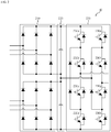
- FIG. 2 is a configuration view of a power cell in FIG.1 .
- a rectifying unit (210) receives two three-phase powers from the phase shift transformer (111) and rectifies the power to a DC voltage.
- the rectifying unit (210) includes two diode rectifiers.
- An output of the rectifying unit (210) is connected to serially-connected DC link capacitors, and each of the two DC link capacitors of a DC unit (220) has a same capacitance.
- An inverter unit (230) synthesizes output voltages of the DC unit (220) and an outputted line-to-line voltage is 5 levels.
- FIG. 3 is another configuration view of FIG.1 , and has the same configuration as in FIG. 1 except for configuration of a power cell (113).
- the power cell (113) of FIG.3 can synthesize output voltages of 5 levels.
- a D1 power cell (113a) can output an 'a' phase voltage of the motor (130)
- an E1 power cell (113b) can output a 'b' phase voltage of the motor (130)
- an F1 power cell (113c) can output a 'c' phase voltage of the motor (130).
- FIG. 4 is a configuration view of a power cell of FIG.3 .
- a rectifying unit (410) includes four diode rectifiers, and operation of an inverter unit (430) is same as in FIG.2 .
- the unit power cells in FIGS. 2 and 4 are different in rated voltage and rated current of power device used in response to required output.
- An output of the phase shift transformer (111) is inputted to the rectifying unit (410), and an output of the rectifying unit (410) is reflected on a DC unit (420).
- Each leg of the inverter unit (230) in FIG.2 includes four serially-arranged switches (230a, 230b, 230c, 230d), and an output voltage is defined by operation of each switch.
- Switching operations of switches of 230a and 230b are complementary and switching operations of switches of 230c and 230d are also complementary.
- each voltage of serially-connected DC link capacitors of the DC unit (220) is defined as E
- switches of 230a and 230b are turned on
- switches of 230c and 230d are turned off
- outputted pole voltage is E.
- switches of 230a and 230c are turned on
- switches of 230b and 230d are turned off, and pole voltage at this time is zero.
- switches of 230a and 230b are turned off, switches of 230c and 230d are turned on, and pole voltage at this time is -E.
- line-to-line voltages outputted by each of the unit power cells (112) of FIG.1 are respectively 5 levels of 2E, E, 0,-E and -2E. Due to the line-to-line voltages outputted by each power cell (112) being defined as five levels, voltages synthesizable by A1 and A2 power cells (112a, 112b) of FIG.1 are nine levels of 4E, 3E, 2E, E,0, -E, -2E, -3E and -4E, and line-to-line voltages outputted to the motor (130) are 17 levels of 8E, 7E, 6E, 5E, 4E, 3E, 2E, E, 0, -E, -2E, -3E, -4E, -5E, -6E, -7E, and -8E. Now, operation of the phase shift transformer (111) of FIGS.1 and 3 will be described.
- the phase shift transformer (111) applies an electrically-insulated 3-phase power to each power cell (112, 113) from an inputted 3-phase power.
- a primary winding of the phase shift transformer (111) is a Y-connection or a delta ( ⁇ )-connection, and a secondary winding outputs a power with a shifted phase and magnitude adequate to requirement of the unit power cells (112, 113).
- a number of an output from the secondary winding of the phase shift transformer (111) is same as a number of the diode rectifiers of rectifying units (210, 410) at the unit power cells (112, 113), and can be defined by the following Equation 1.
- N sec 3 N unit N diode
- N sec is the number of the output from the secondary winding of the phase shift transformer (111)
- N unit is the number of unit power cells (112, 113) connected to each phase of the motor (130)
- N diode is the number of diode rectifiers included in one unit power cell (112, 113).
- N unit is 2 in configurations of FIGS. 1 and 2 , and N diode is 2, N sec becomes 12, and because N unit is 1, N diode is 4 in configurations of FIGS. 3 and 4 , N sec becomes 12.
- a phase shift angle of the secondary winding of the phase shift transformer (111) may be obtained by the following Equation 2.
- ⁇ sec 360 2 N sec deg ree
- ⁇ sec is the phase shift angle between secondary windings. For example, if N sec becomes 12 as in FIGS. 1 and 3 , the phase shift angle between secondary windings is 15°.
- An output voltage of each secondary winding from the phase shift angle between secondary windings thus determined is such that a phase relative to an input voltage at the primary winding is changed as much as the phase shift angle.
- the abovementioned conventional multi-level medium voltage inverter is configured with a phase shift transformer in a single unit.
- the phase shift transformer structured with a single unit suffers from a disadvantage in that, because a required output must be satisfied by one transformer, size and weight of the transformer increase.
- Another disadvantage is that no layout freedom is available to increase an entire system volume-wise and to increase weight as well.
- Still another disadvantage is that if a problem occurs in the primary winding in the conventional phase shift transformer of single unit, an entire system is rendered inoperable.
- US 2010072824 A1 describes a prior art system having multiple modular transformers each including a phase shifted primary winding coupled to an input power source and phase shifted secondary windings each coupled to a power cell.
- the system further includes different phase output lines coupled to a load.
- an exemplary aspect of the present disclosure is to substantially solve at least the above problems and/or disadvantages and to provide at least the advantages below. Accordingly, an aspect of the present disclosure provides a phase shift transformer in multi-level medium voltage inverter configured to modularize a structure, to provide layout freedom and to reduce volume and weight of an entire system.
- phase shift transformer in multi-level medium voltage inverter configured to enable a continuous operation of a motor even if one module is in a fault state.
- phase shift transformer in multi-level medium voltage inverter including a plurality of power cells for driving a motor
- the phase shift transformer comprising: a plurality of modularized phase shift transformers, wherein primary windings of the plurality of modularized phase shift transformers are phase-shifted to each other at a predetermined angle.
- secondary windings of the modularized phase shift transformers comprise a plurality of first connections and a plurality of second connections each phase-shifted at a predetermined angle.
- the first connection includes Y connection and the second connection includes delta ( ⁇ ) connection.
- any one of the plurality of modularized phase shift transformers supplies, as an input power, outputs of the first and second connections to three power cells respectively providing a 3-phase voltage to the motor in the plurality of power cells.
- the secondary windings of the modularized phase shift transformers comprise a plurality of connections each phase-shifted at a predetermined angle.
- any one of the modularized phase shift transformers supplies an input power to any one power cell of the plurality of power cells.
- an input of any one of the power cells is an output from any one of the plurality of connections in the modularized phase shift transformers.
- the plurality of modularized phase shift transformers supplies an input power to any one power cell of the plurality of power cells.
- an input of any one of the power cells is an output from the plurality of modularized phase shift transformers.
- the phase shift transformer in multi-level medium voltage inverter according to the present disclosure has an advantageous effect in that a layout freedom is available to reduce the size of entire system, to increase redundancy of the entire system, whereby a stable operation can be maintained even if the phase shift transformer is faulted.
- the suffixes 'module', 'unit' and 'part' may be used for elements in order to facilitate the disclosure. Significant meanings or roles may not be given to the suffixes themselves and it is understood that the 'module', 'unit' and 'part' may be used together or interchangeably.
- exemplary is merely meant to mean an example, rather than the best. It is also to be appreciated that features, layers and/or elements depicted herein are illustrated with particular dimensions and/or orientations relative to one another for purposes of simplicity and ease of understanding, and that the actual dimensions and/or orientations may differ substantially from that illustrated. That is, in the drawings, the size and relative sizes of layers, regions and/or other elements may be exaggerated or reduced for clarity. Like numbers refer to like elements throughout and explanations that duplicate one another will be omitted.
- first, second, etc. may be used herein to describe various elements, these elements should not be limited by these terms. These terms are only used to distinguish one element from another. For example, a first region/layer could be termed a second region/layer, and, similarly, a second region/layer could be termed a first region/layer without departing from the teachings of the disclosure.
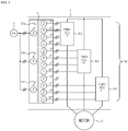
- FIG. 5 is a schematic structural view of a phase shift transformer in a multi-level medium voltage inverter according to an exemplary embodiment of the present disclosure.
- a phase shift transformer (51) is included in a multi-level medium voltage inverter (1), where the inverter (1) converts a 3-phase power, whose root mean square value of line-to-line voltage from a 3-phase input power unit (2) is more than 600v, to a 3-phase voltage driving a 3-phase motor (3).
- the phase shift transformer (51) includes two modularized phase shift transformers (first module 51a, second module 51b).
- a primary winding of the first module (51a) includes a 3-phase Y-connection, and a secondary winding includes a Y-connection and a delta ( ⁇ ) connection, each phased-shifted at 0° and 30°.
- the primary winding of the second module (51b) includes a phase-shifted Z connection, and structure of a secondary winding of the second module (51b) may be identical to that of the first module (51a).
- an output voltage of a unit power cell (52) is 5 levels, and although the motor (3) is formed with two unit power cells for each phase, it should be apparent to the skilled in the art that the number of unit power cells may be extended as demands require.
- Outputs of A1 and A2 power cells are serially connected to output an 'a' phase voltage for the motor (3), B1 and B2 power cells (52c, 52d) output a 'b' phase voltage, and C1 and C2 power cells (52e, 52f) output a 'c' phase voltage.
- the A1, B1 and C1 power cells (52a, 52c, 52e) in FIG.5 receive an output of the first module (51a), and the A2, B2 and C2 power cells (52b, 52d, 52f) in FIG.5 receive an output of the second module (51b).
- Configuration of power cell (52) in FIG.5 is same as that of FIG.2 , and detailed explanation thereto is omitted.
- FIG.5 has exemplified the primary winding of the first module (51a) as Y connection and the primary winding of the second module (51b) as Z connection, the present disclosure is not limited thereto. Furthermore, configuration of secondary winding is not limited to that of FIG.5 , either.
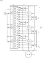
- FIG.6 is a schematic structural view of a phase shift transformer in a multi-level medium voltage inverter according to another exemplary embodiment of the present disclosure, where a phase shift transformer (61) is included inside the multi-level medium voltage inverter (1).
- the multi-level medium voltage inverter (1) converts a 3-phase power, whose root mean square value of line-to-line voltage from a 3-phase input power unit (2) is more than 600v, to a 3-phase voltage driving a 3-phase motor (3).
- the phase shift transformer (61) includes three modularized phase shift transformers (first module 61a, second module 61b, and third module 61c).
- a primary winding of the first module (61a) includes a 5° phase-shifted Z-connection, and a secondary winding includes -15°, 0°, 15° and 30° phase-shifted connections.
- a primary winding of the first module (61a) includes a 0° phase-shifted Y-connection, and a secondary winding may be identical to that of the first module (61a).
- the primary winding of the third module (61c) includes a 5° phase-shifted Z connection, and structure of a secondary winding of the third module (61c) may be identical to that of the first module (61a).
- a power cell (62) may combine an output voltage of 5 levels.
- a D1 power cell (62a) outputs an 'a' phase voltage for the motor (3), an E1 power cell (62b) outputs a 'b' phase voltage, and an F1 power cell (62c) outputs a 'c' phase voltage.
- the power cell (62) of FIG.6 is preferably to have the same configuration as that of FIG.4 , such that detailed explanation thereto is omitted.
- FIG.6 has exemplified the primary windings of the first module (61a) and the third module (61c) as Z connection and the primary winding of the second module (61b) as Y connection, the present disclosure is not limited thereto. Furthermore, configuration of secondary winding is not limited to that of FIG.6 , either.
- FIG.7 is a schematic structural view of a phase shift transformer in a multi-level medium voltage inverter according to still another exemplary embodiment of the present disclosure, where a phase shift transformer (71) is included inside the multi-level medium voltage inverter (1).
- the multi-level medium voltage inverter (1) converts a 3-phase power, whose root mean square value of line-to-line voltage from a 3-phase input power unit (2) is more than 600v, to a 3-phase voltage driving a 3-phase motor (3).
- the phase shift transformer (71) includes three modularized phase shift transformers (first module 71a, second module 71b, and third module 71c).
- FIG.7 The exemplary embodiment of FIG.7 is different from FIG.6 in terms of connection between the phase shift transformer and power cells, where in case of G1 power cell (72a), two input powers in four input powers are received from the first module (71a), one input power is received from the second module (71b), and the balance one is received from the third module (71c).
- H1 power cell (72b) two input powers in four input powers are received from the first module (71b), one input power is received from the second module (71a), and the balance one is received from the third module (71c).
- I1 power cell (72c) two input powers in four input powers are received from the third module (71c), one input power is received from the first module (71a), and the balance one is received from the third module (71b).
- FIG.7 has exemplified the primary windings of the first module (71a) and the third module (71c) as Z connection and the primary winding of the second module (71b) as Y connection, the present disclosure is not limited thereto. Furthermore, configuration of secondary winding is not limited to that of FIG.6 , either.
- FIG.8 is a schematic structural view of a phase shift transformer in a multi-level medium voltage inverter according to still another exemplary embodiment of the present disclosure, where a phase shift transformer (81) is included inside the multi-level medium voltage inverter (1).
- the multi-level medium voltage inverter (1) converts a 3-phase power, whose root mean square value of line-to-line voltage from a 3-phase input power unit (2) is more than 600v, to a 3-phase voltage driving a 3-phase motor (3).
- the phase shift transformer (81) includes three modularized phase shift transformers (first module 81a, second module 81b, and third module 81c).
- a primary winding of the first module (81a) includes a -3.3° phase-shifted Z-connection, and a secondary winding includes 0° and 30° phase-shifted connections.
- a primary winding of the second module (81b) includes a 0° phase-shifted Y-connection, and a secondary winding may be identical to that of the first module (81a).
- the primary winding of the third module (81c) includes a 3.3° phase-shifted Z connection, and structure of a secondary winding of the third module (81c) may be identical to that of the first module (81a).
- a power cell (82) may combine an output voltage of 5 levels.
- A1, A2, and A3 power cells (82a ⁇ 82c) output an 'a' phase voltage for the motor (3)
- B1, B2, B3 power cells (82d ⁇ 82f) output a 'b' phase voltage
- C1, C2 and C3 power cells (82g ⁇ 82i) output a 'c' phase voltage.
- the power cell (82) of FIG.8 is preferably to have the same configuration as that of FIG.2 , such that detailed explanation thereto is omitted.
- FIG.8 has exemplified the primary windings of the first module (81a) and the third module (81c) as Z connection and the primary winding of the second module (81b) as Y connection, the present disclosure is not limited thereto. Furthermore, configuration of secondary winding is not limited to that of FIG.8 , either.
- FIG.9 is a schematic structural view of a phase shift transformer in a multi-level medium voltage inverter according to still another exemplary embodiment of the present disclosure, where a phase shift transformer (91) is included inside the multi-level medium voltage inverter (1) and a 5-level of power cell for each phase of output is used.
- the multi-level medium voltage inverter (1) converts a 3-phase power, whose root mean square value of line-to-line voltage from a 3-phase input power unit (2) is more than 600v, to a 3-phase voltage driving a 3-phase motor (3).
- the phase shift transformer (91) includes five modularized phase shift transformers (first module 91a, second module 91b, third module 91c, fourth module 91d and fifth module 91e).
- a primary winding of the first module (91a) includes a -4° phase-shifted Z-connection, and a secondary winding includes 0° and 30° phase-shifted connections.
- a primary winding of the second module (91b) includes a -2° phase-shifted Y-connection, and a secondary winding may be identical to that of the first module (91a).
- the primary winding of the third module (91c) includes a 0° phase-shifted Z connection, and structure of a secondary winding of the third module (91c) may be identical to that of the first module (91a).
- a primary winding of the fourth module (91d) includes a 2° phase-shifted Y-connection, and a secondary winding may be identical to that of the first module (91a).
- the primary winding of the fifth module (91e) includes a 4° phase-shifted Z connection, and structure of a secondary winding of the fifth module (91e) may be identical to that of the first module (91a).
- a power cell (92) may combine an output voltage of 5 levels.
- A1, A2, A3, A4 and A5 power cells (92a ⁇ 92e) output an 'a' phase voltage for the motor (3)
- B1, B2, B3, B4 and B5 power cells (92f ⁇ 92j) output a 'b' phase voltage
- C1, C2, C3, C4 and C5 power cells (92k ⁇ 92o) output a 'c' phase voltage.
- Each power cell (92) of FIG.9 is preferably to have the same configuration as that of FIG.2 , such that detailed explanation thereto is omitted.
- FIG.9 has exemplified the primary windings of the first module (91a), the third module (91c) and the fifth module (91e) as Z connection, and the primary windings of the second module (91b) and the fourth module (91d) as Y connection, the present disclosure is not limited thereto. Furthermore, configuration of secondary winding is not limited to that of FIG.9 , either.
- the present disclosure is such that a conventional phase shift transformer configured in a single unit is modularized and used in a multi-level medium voltage inverter including the power cells shown in FIG. 2 or FIG.4 .
- the power cells used in the present disclosure includes two or four diode rectifiers at an input terminal as shown in FIG.2 or FIG.4 , and each output terminal of the diode rectifier is formed with DC link capacitors, where the DC link capacitors are serially connected to include a DC unit (220 or 420).
- each voltage of the DC link capacitor is defined as E
- link-to-link voltages outputted by the unit power cells are respectively 2E, E, 0, -E and -2E.
- a phase shift angle of secondary winding of the phase shift transformer according to the present disclosure is determined by the Equations 1 and 2. Furthermore, a phase shift angle of primary winding of the phase shift transformer according to the present invention is determined by the Equation 5.
- ⁇ prim 360 N m _ T 1 N sec _ out 1 N diode _ pulse deg ree , where, N m_T is the number of modules of the phase shift transformer, N sec_ out is the number of outputs at the secondary winding of a single phase shift transformer, and N diode_pulse is the number of pulses of diode rectifier.
- N m_T is 2
- N sec_ out is 6
- N diode_pulse is 6, whereby ⁇ prim is 5°.
- Capacity of modularized phase shift transformer according to the present disclosure has a relationship with capacity of the conventional single unit-type phase shift transformer in the following manner of Equation 6.
- S m _ T S conv N m _ T , where, S m_T is an apparent power of each modularized phase shift transformer according to the present disclosure, and S conv is an apparent power of the conventional single unit-type phase shift transformer.
- the modularized phase shift transformer is advantageous over the conventional single unit type phase shift transformer in that capacity is small to reduce a winding window and to reduce an entire size and weight. As a result, size and weight of the phase shift transformer are reduced to reduce the size and weight of an entire system.
- the modularized phase shift transformer according to the present disclosure has a transformer as small as N m_T , resultantly providing a layout freedom for an entire system and flexibility in design.
- the modularized phase shift transformer according to the present disclosure is advantageous in that if a primary winding of one module at the modularized phase shift transformer is faulted, a power cell connected to the faulted module is detoured to enable a continued operation under a reduced output.
- the modularized phase shift transformer in a multi-level medium voltage inverter according to the present disclosure has an industrial applicability in that redundancy of an entire system can be enhanced due to the structural characteristics thus described.
Landscapes
- Engineering & Computer Science (AREA)
- Power Engineering (AREA)
- Inverter Devices (AREA)
- Charge And Discharge Circuits For Batteries Or The Like (AREA)
Claims (9)
- Transformateur déphaseur (51) dans un onduleur à tension moyenne à plusieurs niveaux (1) comprenant une pluralité de cellules électriques (52a à 52f) ; destiné à entraîner un moteur (3), le transformateur déphaseur (51) comprenant : une pluralité de transformateurs déphaseurs modularisés (51a, 51b), dans lequel des enroulements primaires de la pluralité de transformateurs déphaseurs modularisés (51a, 51b) sont déphasés les uns par rapport aux autres selon un angle prédéterminé ; caractérisé en ce que l'angle prédéterminé est déterminé par l'équation suivante :

- Transformateur déphaseur (51) selon la revendication 1, dans lequel des enroulements secondaires des transformateurs déphaseurs modularisés (51a, 51b) comprennent une pluralité de premières connexions et une pluralité de deuxièmes connexions, chacune déphasée selon un angle prédéterminé.
- Transformateur déphaseur (51) selon la revendication 2, dans lequel la première connexion comprend une connexion en Y et la deuxième connexion comprend une connexion delta (Δ).
- Transformateur déphaseur (51) selon la revendication 2 ou 3, dans lequel l'un quelconque de la pluralité de transformateurs déphaseurs modularisés (51a, 51b) fournit, en tant qu'énergie d'entrée, des sorties des premières et deuxièmes connexions à trois cellules électriques fournissant respectivement une tension triphasée au moteur (3) dans la pluralité de cellules électriques (52a à 52f).
- Transformateur déphaseur (51) selon l'une quelconque des revendications 1 à 4, dans lequel les enroulements secondaires des transformateurs déphaseurs modularisés comprennent une pluralité de connexions, chacune déphasée selon un angle prédéterminé.
- Transformateur déphaseur (51) selon la revendication 5, dans lequel l'un quelconque des transformateurs déphaseurs modularisés (51a, 51b) fournit une énergie d'entrée à une cellule électrique quelconque de la pluralité de cellules électriques (52a à 52f).
- Transformateur déphaseur (51) selon la revendication 6, dans lequel une entrée de l'une quelconque des cellules électriques (52a à 52f) est une sortie depuis l'une quelconque des connexions dans les transformateurs déphaseurs modularisés (51a, 51b).
- Transformateur déphaseur (51) selon l'une quelconque des revendications 5 à 7, dans lequel la pluralité de transformateurs déphaseurs modularisés (51a, 51b) fournit une énergie d'entrée à une cellule électrique quelconque de la pluralité de cellules électriques (52a à 52f).
- Transformateur déphaseur (51) selon la revendication 8, dans lequel une entrée de l'une quelconque des cellules électriques (52a à 52f) est une sortie depuis la pluralité de transformateurs déphaseurs modularisés (51a, 51b).
Applications Claiming Priority (1)
| Application Number | Priority Date | Filing Date | Title |
|---|---|---|---|
| KR1020110097961A KR101545277B1 (ko) | 2011-09-28 | 2011-09-28 | 멀티레벨 고압 인버터의 위상천이 변압기 |
Publications (3)
| Publication Number | Publication Date |
|---|---|
| EP2575249A2 EP2575249A2 (fr) | 2013-04-03 |
| EP2575249A3 EP2575249A3 (fr) | 2017-07-05 |
| EP2575249B1 true EP2575249B1 (fr) | 2019-11-06 |
Family
ID=47115207
Family Applications (1)
| Application Number | Title | Priority Date | Filing Date |
|---|---|---|---|
| EP12180533.7A Active EP2575249B1 (fr) | 2011-09-28 | 2012-08-15 | Transformateur à décalage de phase dans un onduleur de tension moyenne à plusieurs niveaux |
Country Status (6)
| Country | Link |
|---|---|
| US (1) | US9136772B2 (fr) |
| EP (1) | EP2575249B1 (fr) |
| JP (1) | JP5781995B2 (fr) |
| KR (1) | KR101545277B1 (fr) |
| CN (1) | CN103036456B (fr) |
| ES (1) | ES2767178T3 (fr) |
Families Citing this family (9)
| Publication number | Priority date | Publication date | Assignee | Title |
|---|---|---|---|---|
| KR101769176B1 (ko) * | 2013-04-10 | 2017-08-17 | 엘에스산전 주식회사 | 멀티레벨 인버터 시스템 |
| KR101791288B1 (ko) * | 2013-06-05 | 2017-10-27 | 엘에스산전 주식회사 | 멀티 레벨 인버터 |
| KR101791289B1 (ko) * | 2013-06-17 | 2017-10-27 | 엘에스산전 주식회사 | 멀티레벨 인버터 |
| KR101791290B1 (ko) | 2013-07-02 | 2017-11-20 | 엘에스산전 주식회사 | 멀티레벨 고압 인버터 |
| KR101792039B1 (ko) * | 2013-08-08 | 2017-11-01 | 엘에스산전 주식회사 | 고압인버터의 위상치환 변압기의 위상각 결정방법 |
| KR101768256B1 (ko) | 2013-08-29 | 2017-08-14 | 엘에스산전 주식회사 | 듀얼 구조의 파워 셀을 구비하는 인버터 |
| JP6146284B2 (ja) * | 2013-12-02 | 2017-06-14 | 富士電機株式会社 | 電力変換装置 |
| CA2979931A1 (fr) | 2015-03-16 | 2016-09-22 | Dsm Ip Assets B.V. | Udp-glycosyltransferases |
| JP6887057B1 (ja) * | 2019-07-26 | 2021-06-16 | 東芝三菱電機産業システム株式会社 | 電力変換装置及び欠相検知装置 |
Family Cites Families (15)
| Publication number | Priority date | Publication date | Assignee | Title |
|---|---|---|---|---|
| US5638263A (en) | 1994-03-01 | 1997-06-10 | Halmar Robicon Group | Low and medium voltage PWM AC/DC power conversion method and apparatus |
| US6014323A (en) * | 1997-08-08 | 2000-01-11 | Robicon Corporation | Multiphase power converter |
| GB2330254B (en) * | 1997-10-09 | 2000-10-18 | Toshiba Kk | Multiple inverter system |
| US6340851B1 (en) | 1998-03-23 | 2002-01-22 | Electric Boat Corporation | Modular transformer arrangement for use with multi-level power converter |
| CN2405375Y (zh) * | 1999-09-05 | 2000-11-08 | 叶昌瑶 | 三相智能模块交流调控硅整流器 |
| CA2418315A1 (fr) * | 2002-12-24 | 2004-06-24 | Delta Transformers Of Canada (1999) Ltd. | Transformateur a dephasage reglable sur le terrain |
| BRPI0616123B1 (pt) * | 2005-09-09 | 2018-05-29 | Siemens Aktiengesellschaft | Método de controlar um sistema de distribuição de energia, método de operar um sistema de distribuição de energia e sistema de distribuição de energia |
| JP4512117B2 (ja) | 2007-05-23 | 2010-07-28 | 株式会社日立製作所 | 多重電力変換装置、及び多重変圧器 |
| KR20090100655A (ko) * | 2008-03-20 | 2009-09-24 | 엘에스산전 주식회사 | 멀티 레벨 인버터 |
| US8200460B2 (en) * | 2008-07-24 | 2012-06-12 | Siemens Industry, Inc. | Method of designing a multi-winding device |
| US7830681B2 (en) * | 2008-09-24 | 2010-11-09 | Teco-Westinghouse Motor Company | Modular multi-pulse transformer rectifier for use in asymmetric multi-level power converter |
| US7940537B2 (en) * | 2008-12-31 | 2011-05-10 | Teco-Westinghouse Motor Company | Partial regeneration in a multi-level power inverter |
| US8223515B2 (en) * | 2009-02-26 | 2012-07-17 | TECO—Westinghouse Motor Company | Pre-charging an inverter using an auxiliary winding |
| US8711530B2 (en) * | 2009-06-30 | 2014-04-29 | Teco-Westinghouse Motor Company | Pluggable power cell for an inverter |
| US8536740B2 (en) * | 2010-08-23 | 2013-09-17 | Schlumberger Technology Corporation | Variable frequency drive with dielectric fluid-immersed transformer |
-
2011
- 2011-09-28 KR KR1020110097961A patent/KR101545277B1/ko not_active Expired - Fee Related
-
2012
- 2012-08-15 EP EP12180533.7A patent/EP2575249B1/fr active Active
- 2012-08-15 ES ES12180533T patent/ES2767178T3/es active Active
- 2012-08-24 JP JP2012185041A patent/JP5781995B2/ja not_active Expired - Fee Related
- 2012-08-30 US US13/599,890 patent/US9136772B2/en not_active Expired - Fee Related
- 2012-09-25 CN CN201210362466.7A patent/CN103036456B/zh not_active Expired - Fee Related
Non-Patent Citations (1)
| Title |
|---|
| None * |
Also Published As
| Publication number | Publication date |
|---|---|
| KR101545277B1 (ko) | 2015-08-18 |
| EP2575249A2 (fr) | 2013-04-03 |
| ES2767178T3 (es) | 2020-06-16 |
| JP2013074789A (ja) | 2013-04-22 |
| CN103036456B (zh) | 2015-09-02 |
| JP5781995B2 (ja) | 2015-09-24 |
| CN103036456A (zh) | 2013-04-10 |
| US9136772B2 (en) | 2015-09-15 |
| US20130076280A1 (en) | 2013-03-28 |
| KR20130034110A (ko) | 2013-04-05 |
| EP2575249A3 (fr) | 2017-07-05 |
Similar Documents
| Publication | Publication Date | Title |
|---|---|---|
| EP2575249B1 (fr) | Transformateur à décalage de phase dans un onduleur de tension moyenne à plusieurs niveaux | |
| EP2748917B1 (fr) | Convertisseur cc-cc bidirectionnel non-isolé avec des cellules en cascade | |
| EP3627684B1 (fr) | Dispositif de conversion de puissance | |
| JP5097828B2 (ja) | 電力変換装置 | |
| US6963147B2 (en) | Power converter and power unit | |
| EP2548259B1 (fr) | Égalisation de l'état de charge d'accumulateurs | |
| EP2822164B1 (fr) | Onduleur à moyenne tension et multiniveau | |
| CN104769832B (zh) | 用于级联多级逆变器的故障旁路的控制 | |
| EP2541752B1 (fr) | Dispositif de conversion d'énergie électrique | |
| US20130003431A1 (en) | Multilevel power converter and methods of manufacturing and operation thereof | |
| EP2814166B1 (fr) | Onduleur multiniveau avec une pluralité des sous-modules | |
| EP3068029A1 (fr) | Système d'onduleur | |
| EP2619895A1 (fr) | Convertisseur multi-niveau à deux bornes | |
| JP6681476B2 (ja) | 電力変換装置および電力変換装置の制御方法 | |
| JP2018011420A (ja) | 電力変換装置 | |
| CN108352780B (zh) | 用于处理ac侧故障的模块化多电平转换器 | |
| JP6658369B2 (ja) | 電力変換装置 | |
| US7313008B2 (en) | Converter circuit for producing low harmonics | |
| WO2015076776A1 (fr) | Système de correction de facteur de puissance active multiphasé | |
| CN106160540A (zh) | 电力变换装置 | |
| WO2015136552A2 (fr) | Structure de sous-module de convertisseur modulaire multiniveaux (mmc) permettant de réduire les pertes de commutation | |
| EP2840706B1 (fr) | Procédé de détermination d'angle de phase dans un transformateur de déphasage pour inverseur de moyenne tension | |
| EP3691107A1 (fr) | Système d'onduleur | |
| EP4356506B1 (fr) | Commande insensible aux défaillances d'un transformateur à semi-conducteurs | |
| EP3493391A1 (fr) | Convertisseur de niveau sept à phase unique |
Legal Events
| Date | Code | Title | Description |
|---|---|---|---|
| PUAI | Public reference made under article 153(3) epc to a published international application that has entered the european phase |
Free format text: ORIGINAL CODE: 0009012 |
|
| AK | Designated contracting states |
Kind code of ref document: A2 Designated state(s): AL AT BE BG CH CY CZ DE DK EE ES FI FR GB GR HR HU IE IS IT LI LT LU LV MC MK MT NL NO PL PT RO RS SE SI SK SM TR |
|
| AX | Request for extension of the european patent |
Extension state: BA ME |
|
| PUAL | Search report despatched |
Free format text: ORIGINAL CODE: 0009013 |
|
| AK | Designated contracting states |
Kind code of ref document: A3 Designated state(s): AL AT BE BG CH CY CZ DE DK EE ES FI FR GB GR HR HU IE IS IT LI LT LU LV MC MK MT NL NO PL PT RO RS SE SI SK SM TR |
|
| AX | Request for extension of the european patent |
Extension state: BA ME |
|
| RIC1 | Information provided on ipc code assigned before grant |
Ipc: H02M 5/42 20060101AFI20170530BHEP Ipc: H02M 7/49 20070101ALI20170530BHEP |
|
| STAA | Information on the status of an ep patent application or granted ep patent |
Free format text: STATUS: REQUEST FOR EXAMINATION WAS MADE |
|
| 17P | Request for examination filed |
Effective date: 20171122 |
|
| RBV | Designated contracting states (corrected) |
Designated state(s): AL AT BE BG CH CY CZ DE DK EE ES FI FR GB GR HR HU IE IS IT LI LT LU LV MC MK MT NL NO PL PT RO RS SE SI SK SM TR |
|
| GRAP | Despatch of communication of intention to grant a patent |
Free format text: ORIGINAL CODE: EPIDOSNIGR1 |
|
| STAA | Information on the status of an ep patent application or granted ep patent |
Free format text: STATUS: GRANT OF PATENT IS INTENDED |
|
| INTG | Intention to grant announced |
Effective date: 20190627 |
|
| GRAS | Grant fee paid |
Free format text: ORIGINAL CODE: EPIDOSNIGR3 |
|
| GRAA | (expected) grant |
Free format text: ORIGINAL CODE: 0009210 |
|
| STAA | Information on the status of an ep patent application or granted ep patent |
Free format text: STATUS: THE PATENT HAS BEEN GRANTED |
|
| AK | Designated contracting states |
Kind code of ref document: B1 Designated state(s): AL AT BE BG CH CY CZ DE DK EE ES FI FR GB GR HR HU IE IS IT LI LT LU LV MC MK MT NL NO PL PT RO RS SE SI SK SM TR |
|
| REG | Reference to a national code |
Ref country code: GB Ref legal event code: FG4D |
|
| REG | Reference to a national code |
Ref country code: CH Ref legal event code: EP Ref country code: AT Ref legal event code: REF Ref document number: 1200156 Country of ref document: AT Kind code of ref document: T Effective date: 20191115 |
|
| REG | Reference to a national code |
Ref country code: DE Ref legal event code: R096 Ref document number: 602012065387 Country of ref document: DE |
|
| REG | Reference to a national code |
Ref country code: IE Ref legal event code: FG4D |
|
| REG | Reference to a national code |
Ref country code: NL Ref legal event code: MP Effective date: 20191106 |
|
| REG | Reference to a national code |
Ref country code: LT Ref legal event code: MG4D |
|
| PG25 | Lapsed in a contracting state [announced via postgrant information from national office to epo] |
Ref country code: BG Free format text: LAPSE BECAUSE OF FAILURE TO SUBMIT A TRANSLATION OF THE DESCRIPTION OR TO PAY THE FEE WITHIN THE PRESCRIBED TIME-LIMIT Effective date: 20200206 Ref country code: FI Free format text: LAPSE BECAUSE OF FAILURE TO SUBMIT A TRANSLATION OF THE DESCRIPTION OR TO PAY THE FEE WITHIN THE PRESCRIBED TIME-LIMIT Effective date: 20191106 Ref country code: GR Free format text: LAPSE BECAUSE OF FAILURE TO SUBMIT A TRANSLATION OF THE DESCRIPTION OR TO PAY THE FEE WITHIN THE PRESCRIBED TIME-LIMIT Effective date: 20200207 Ref country code: LT Free format text: LAPSE BECAUSE OF FAILURE TO SUBMIT A TRANSLATION OF THE DESCRIPTION OR TO PAY THE FEE WITHIN THE PRESCRIBED TIME-LIMIT Effective date: 20191106 Ref country code: NL Free format text: LAPSE BECAUSE OF FAILURE TO SUBMIT A TRANSLATION OF THE DESCRIPTION OR TO PAY THE FEE WITHIN THE PRESCRIBED TIME-LIMIT Effective date: 20191106 Ref country code: PL Free format text: LAPSE BECAUSE OF FAILURE TO SUBMIT A TRANSLATION OF THE DESCRIPTION OR TO PAY THE FEE WITHIN THE PRESCRIBED TIME-LIMIT Effective date: 20191106 Ref country code: NO Free format text: LAPSE BECAUSE OF FAILURE TO SUBMIT A TRANSLATION OF THE DESCRIPTION OR TO PAY THE FEE WITHIN THE PRESCRIBED TIME-LIMIT Effective date: 20200206 Ref country code: PT Free format text: LAPSE BECAUSE OF FAILURE TO SUBMIT A TRANSLATION OF THE DESCRIPTION OR TO PAY THE FEE WITHIN THE PRESCRIBED TIME-LIMIT Effective date: 20200306 Ref country code: LV Free format text: LAPSE BECAUSE OF FAILURE TO SUBMIT A TRANSLATION OF THE DESCRIPTION OR TO PAY THE FEE WITHIN THE PRESCRIBED TIME-LIMIT Effective date: 20191106 Ref country code: SE Free format text: LAPSE BECAUSE OF FAILURE TO SUBMIT A TRANSLATION OF THE DESCRIPTION OR TO PAY THE FEE WITHIN THE PRESCRIBED TIME-LIMIT Effective date: 20191106 |
|
| PG25 | Lapsed in a contracting state [announced via postgrant information from national office to epo] |
Ref country code: IS Free format text: LAPSE BECAUSE OF FAILURE TO SUBMIT A TRANSLATION OF THE DESCRIPTION OR TO PAY THE FEE WITHIN THE PRESCRIBED TIME-LIMIT Effective date: 20200306 Ref country code: RS Free format text: LAPSE BECAUSE OF FAILURE TO SUBMIT A TRANSLATION OF THE DESCRIPTION OR TO PAY THE FEE WITHIN THE PRESCRIBED TIME-LIMIT Effective date: 20191106 Ref country code: HR Free format text: LAPSE BECAUSE OF FAILURE TO SUBMIT A TRANSLATION OF THE DESCRIPTION OR TO PAY THE FEE WITHIN THE PRESCRIBED TIME-LIMIT Effective date: 20191106 |
|
| REG | Reference to a national code |
Ref country code: ES Ref legal event code: FG2A Ref document number: 2767178 Country of ref document: ES Kind code of ref document: T3 Effective date: 20200616 |
|
| PG25 | Lapsed in a contracting state [announced via postgrant information from national office to epo] |
Ref country code: AL Free format text: LAPSE BECAUSE OF FAILURE TO SUBMIT A TRANSLATION OF THE DESCRIPTION OR TO PAY THE FEE WITHIN THE PRESCRIBED TIME-LIMIT Effective date: 20191106 |
|
| PG25 | Lapsed in a contracting state [announced via postgrant information from national office to epo] |
Ref country code: DK Free format text: LAPSE BECAUSE OF FAILURE TO SUBMIT A TRANSLATION OF THE DESCRIPTION OR TO PAY THE FEE WITHIN THE PRESCRIBED TIME-LIMIT Effective date: 20191106 Ref country code: RO Free format text: LAPSE BECAUSE OF FAILURE TO SUBMIT A TRANSLATION OF THE DESCRIPTION OR TO PAY THE FEE WITHIN THE PRESCRIBED TIME-LIMIT Effective date: 20191106 Ref country code: CZ Free format text: LAPSE BECAUSE OF FAILURE TO SUBMIT A TRANSLATION OF THE DESCRIPTION OR TO PAY THE FEE WITHIN THE PRESCRIBED TIME-LIMIT Effective date: 20191106 Ref country code: EE Free format text: LAPSE BECAUSE OF FAILURE TO SUBMIT A TRANSLATION OF THE DESCRIPTION OR TO PAY THE FEE WITHIN THE PRESCRIBED TIME-LIMIT Effective date: 20191106 |
|
| PGFP | Annual fee paid to national office [announced via postgrant information from national office to epo] |
Ref country code: FR Payment date: 20200609 Year of fee payment: 9 |
|
| REG | Reference to a national code |
Ref country code: DE Ref legal event code: R097 Ref document number: 602012065387 Country of ref document: DE |
|
| REG | Reference to a national code |
Ref country code: AT Ref legal event code: MK05 Ref document number: 1200156 Country of ref document: AT Kind code of ref document: T Effective date: 20191106 |
|
| PG25 | Lapsed in a contracting state [announced via postgrant information from national office to epo] |
Ref country code: SK Free format text: LAPSE BECAUSE OF FAILURE TO SUBMIT A TRANSLATION OF THE DESCRIPTION OR TO PAY THE FEE WITHIN THE PRESCRIBED TIME-LIMIT Effective date: 20191106 Ref country code: SM Free format text: LAPSE BECAUSE OF FAILURE TO SUBMIT A TRANSLATION OF THE DESCRIPTION OR TO PAY THE FEE WITHIN THE PRESCRIBED TIME-LIMIT Effective date: 20191106 |
|
| PLBE | No opposition filed within time limit |
Free format text: ORIGINAL CODE: 0009261 |
|
| STAA | Information on the status of an ep patent application or granted ep patent |
Free format text: STATUS: NO OPPOSITION FILED WITHIN TIME LIMIT |
|
| 26N | No opposition filed |
Effective date: 20200807 |
|
| PG25 | Lapsed in a contracting state [announced via postgrant information from national office to epo] |
Ref country code: SI Free format text: LAPSE BECAUSE OF FAILURE TO SUBMIT A TRANSLATION OF THE DESCRIPTION OR TO PAY THE FEE WITHIN THE PRESCRIBED TIME-LIMIT Effective date: 20191106 Ref country code: AT Free format text: LAPSE BECAUSE OF FAILURE TO SUBMIT A TRANSLATION OF THE DESCRIPTION OR TO PAY THE FEE WITHIN THE PRESCRIBED TIME-LIMIT Effective date: 20191106 |
|
| PG25 | Lapsed in a contracting state [announced via postgrant information from national office to epo] |
Ref country code: MC Free format text: LAPSE BECAUSE OF FAILURE TO SUBMIT A TRANSLATION OF THE DESCRIPTION OR TO PAY THE FEE WITHIN THE PRESCRIBED TIME-LIMIT Effective date: 20191106 |
|
| REG | Reference to a national code |
Ref country code: CH Ref legal event code: PL |
|
| PG25 | Lapsed in a contracting state [announced via postgrant information from national office to epo] |
Ref country code: LI Free format text: LAPSE BECAUSE OF NON-PAYMENT OF DUE FEES Effective date: 20200831 Ref country code: CH Free format text: LAPSE BECAUSE OF NON-PAYMENT OF DUE FEES Effective date: 20200831 Ref country code: LU Free format text: LAPSE BECAUSE OF NON-PAYMENT OF DUE FEES Effective date: 20200815 |
|
| REG | Reference to a national code |
Ref country code: BE Ref legal event code: MM Effective date: 20200831 |
|
| PG25 | Lapsed in a contracting state [announced via postgrant information from national office to epo] |
Ref country code: IE Free format text: LAPSE BECAUSE OF NON-PAYMENT OF DUE FEES Effective date: 20200815 Ref country code: BE Free format text: LAPSE BECAUSE OF NON-PAYMENT OF DUE FEES Effective date: 20200831 |
|
| PG25 | Lapsed in a contracting state [announced via postgrant information from national office to epo] |
Ref country code: TR Free format text: LAPSE BECAUSE OF FAILURE TO SUBMIT A TRANSLATION OF THE DESCRIPTION OR TO PAY THE FEE WITHIN THE PRESCRIBED TIME-LIMIT Effective date: 20191106 Ref country code: MT Free format text: LAPSE BECAUSE OF FAILURE TO SUBMIT A TRANSLATION OF THE DESCRIPTION OR TO PAY THE FEE WITHIN THE PRESCRIBED TIME-LIMIT Effective date: 20191106 Ref country code: CY Free format text: LAPSE BECAUSE OF FAILURE TO SUBMIT A TRANSLATION OF THE DESCRIPTION OR TO PAY THE FEE WITHIN THE PRESCRIBED TIME-LIMIT Effective date: 20191106 |
|
| PG25 | Lapsed in a contracting state [announced via postgrant information from national office to epo] |
Ref country code: MK Free format text: LAPSE BECAUSE OF FAILURE TO SUBMIT A TRANSLATION OF THE DESCRIPTION OR TO PAY THE FEE WITHIN THE PRESCRIBED TIME-LIMIT Effective date: 20191106 |
|
| PG25 | Lapsed in a contracting state [announced via postgrant information from national office to epo] |
Ref country code: FR Free format text: LAPSE BECAUSE OF NON-PAYMENT OF DUE FEES Effective date: 20210831 |
|
| PGFP | Annual fee paid to national office [announced via postgrant information from national office to epo] |
Ref country code: IT Payment date: 20220606 Year of fee payment: 11 Ref country code: GB Payment date: 20220607 Year of fee payment: 11 |
|
| PGFP | Annual fee paid to national office [announced via postgrant information from national office to epo] |
Ref country code: ES Payment date: 20220908 Year of fee payment: 11 Ref country code: DE Payment date: 20220603 Year of fee payment: 11 |
|
| REG | Reference to a national code |
Ref country code: DE Ref legal event code: R119 Ref document number: 602012065387 Country of ref document: DE |
|
| GBPC | Gb: european patent ceased through non-payment of renewal fee |
Effective date: 20230815 |
|
| PG25 | Lapsed in a contracting state [announced via postgrant information from national office to epo] |
Ref country code: GB Free format text: LAPSE BECAUSE OF NON-PAYMENT OF DUE FEES Effective date: 20230815 |
|
| PG25 | Lapsed in a contracting state [announced via postgrant information from national office to epo] |
Ref country code: IT Free format text: LAPSE BECAUSE OF NON-PAYMENT OF DUE FEES Effective date: 20230815 Ref country code: GB Free format text: LAPSE BECAUSE OF NON-PAYMENT OF DUE FEES Effective date: 20230815 Ref country code: DE Free format text: LAPSE BECAUSE OF NON-PAYMENT OF DUE FEES Effective date: 20240301 |
|
| REG | Reference to a national code |
Ref country code: ES Ref legal event code: FD2A Effective date: 20240930 |
|
| PG25 | Lapsed in a contracting state [announced via postgrant information from national office to epo] |
Ref country code: ES Free format text: LAPSE BECAUSE OF NON-PAYMENT OF DUE FEES Effective date: 20230816 |
|
| PG25 | Lapsed in a contracting state [announced via postgrant information from national office to epo] |
Ref country code: ES Free format text: LAPSE BECAUSE OF NON-PAYMENT OF DUE FEES Effective date: 20230816 |