EP2575193A1 - Battery pack - Google Patents
Battery pack Download PDFInfo
- Publication number
- EP2575193A1 EP2575193A1 EP20120186537 EP12186537A EP2575193A1 EP 2575193 A1 EP2575193 A1 EP 2575193A1 EP 20120186537 EP20120186537 EP 20120186537 EP 12186537 A EP12186537 A EP 12186537A EP 2575193 A1 EP2575193 A1 EP 2575193A1
- Authority
- EP
- European Patent Office
- Prior art keywords
- insulating
- battery pack
- single cells
- inner cover
- members
- Prior art date
- Legal status (The legal status is an assumption and is not a legal conclusion. Google has not performed a legal analysis and makes no representation as to the accuracy of the status listed.)
- Granted
Links
- 125000006850 spacer group Chemical group 0.000 claims abstract description 59
- 239000003507 refrigerant Substances 0.000 description 34
- 238000004891 communication Methods 0.000 description 6
- 230000003014 reinforcing effect Effects 0.000 description 6
- 238000005452 bending Methods 0.000 description 3
- 238000003780 insertion Methods 0.000 description 3
- 230000037431 insertion Effects 0.000 description 3
- 229920003002 synthetic resin Polymers 0.000 description 3
- 239000000057 synthetic resin Substances 0.000 description 3
- 229910000831 Steel Inorganic materials 0.000 description 2
- 238000001816 cooling Methods 0.000 description 2
- 238000013461 design Methods 0.000 description 2
- 238000009413 insulation Methods 0.000 description 2
- 239000000463 material Substances 0.000 description 2
- 239000002184 metal Substances 0.000 description 2
- 238000000034 method Methods 0.000 description 2
- 238000000465 moulding Methods 0.000 description 2
- 239000010959 steel Substances 0.000 description 2
- HBBGRARXTFLTSG-UHFFFAOYSA-N Lithium ion Chemical compound [Li+] HBBGRARXTFLTSG-UHFFFAOYSA-N 0.000 description 1
- 239000004020 conductor Substances 0.000 description 1
- 238000006073 displacement reaction Methods 0.000 description 1
- 229910001416 lithium ion Inorganic materials 0.000 description 1
- 238000005259 measurement Methods 0.000 description 1
Images


Classifications
-
- H—ELECTRICITY
- H01—ELECTRIC ELEMENTS
- H01M—PROCESSES OR MEANS, e.g. BATTERIES, FOR THE DIRECT CONVERSION OF CHEMICAL ENERGY INTO ELECTRICAL ENERGY
- H01M50/00—Constructional details or processes of manufacture of the non-active parts of electrochemical cells other than fuel cells, e.g. hybrid cells
- H01M50/20—Mountings; Secondary casings or frames; Racks, modules or packs; Suspension devices; Shock absorbers; Transport or carrying devices; Holders
- H01M50/204—Racks, modules or packs for multiple batteries or multiple cells
- H01M50/207—Racks, modules or packs for multiple batteries or multiple cells characterised by their shape
- H01M50/209—Racks, modules or packs for multiple batteries or multiple cells characterised by their shape adapted for prismatic or rectangular cells
-
- H—ELECTRICITY
- H01—ELECTRIC ELEMENTS
- H01M—PROCESSES OR MEANS, e.g. BATTERIES, FOR THE DIRECT CONVERSION OF CHEMICAL ENERGY INTO ELECTRICAL ENERGY
- H01M50/00—Constructional details or processes of manufacture of the non-active parts of electrochemical cells other than fuel cells, e.g. hybrid cells
- H01M50/20—Mountings; Secondary casings or frames; Racks, modules or packs; Suspension devices; Shock absorbers; Transport or carrying devices; Holders
- H01M50/233—Mountings; Secondary casings or frames; Racks, modules or packs; Suspension devices; Shock absorbers; Transport or carrying devices; Holders characterised by physical properties of casings or racks, e.g. dimensions
-
- H—ELECTRICITY
- H01—ELECTRIC ELEMENTS
- H01M—PROCESSES OR MEANS, e.g. BATTERIES, FOR THE DIRECT CONVERSION OF CHEMICAL ENERGY INTO ELECTRICAL ENERGY
- H01M50/00—Constructional details or processes of manufacture of the non-active parts of electrochemical cells other than fuel cells, e.g. hybrid cells
- H01M50/20—Mountings; Secondary casings or frames; Racks, modules or packs; Suspension devices; Shock absorbers; Transport or carrying devices; Holders
- H01M50/271—Lids or covers for the racks or secondary casings
- H01M50/273—Lids or covers for the racks or secondary casings characterised by the material
-
- H—ELECTRICITY
- H01—ELECTRIC ELEMENTS
- H01M—PROCESSES OR MEANS, e.g. BATTERIES, FOR THE DIRECT CONVERSION OF CHEMICAL ENERGY INTO ELECTRICAL ENERGY
- H01M50/00—Constructional details or processes of manufacture of the non-active parts of electrochemical cells other than fuel cells, e.g. hybrid cells
- H01M50/20—Mountings; Secondary casings or frames; Racks, modules or packs; Suspension devices; Shock absorbers; Transport or carrying devices; Holders
- H01M50/289—Mountings; Secondary casings or frames; Racks, modules or packs; Suspension devices; Shock absorbers; Transport or carrying devices; Holders characterised by spacing elements or positioning means within frames, racks or packs
- H01M50/291—Mountings; Secondary casings or frames; Racks, modules or packs; Suspension devices; Shock absorbers; Transport or carrying devices; Holders characterised by spacing elements or positioning means within frames, racks or packs characterised by their shape
-
- H—ELECTRICITY
- H01—ELECTRIC ELEMENTS
- H01M—PROCESSES OR MEANS, e.g. BATTERIES, FOR THE DIRECT CONVERSION OF CHEMICAL ENERGY INTO ELECTRICAL ENERGY
- H01M50/00—Constructional details or processes of manufacture of the non-active parts of electrochemical cells other than fuel cells, e.g. hybrid cells
- H01M50/40—Separators; Membranes; Diaphragms; Spacing elements inside cells
-
- H—ELECTRICITY
- H01—ELECTRIC ELEMENTS
- H01M—PROCESSES OR MEANS, e.g. BATTERIES, FOR THE DIRECT CONVERSION OF CHEMICAL ENERGY INTO ELECTRICAL ENERGY
- H01M50/00—Constructional details or processes of manufacture of the non-active parts of electrochemical cells other than fuel cells, e.g. hybrid cells
- H01M50/50—Current conducting connections for cells or batteries
- H01M50/502—Interconnectors for connecting terminals of adjacent batteries; Interconnectors for connecting cells outside a battery casing
- H01M50/507—Interconnectors for connecting terminals of adjacent batteries; Interconnectors for connecting cells outside a battery casing comprising an arrangement of two or more busbars within a container structure, e.g. busbar modules
-
- H—ELECTRICITY
- H01—ELECTRIC ELEMENTS
- H01M—PROCESSES OR MEANS, e.g. BATTERIES, FOR THE DIRECT CONVERSION OF CHEMICAL ENERGY INTO ELECTRICAL ENERGY
- H01M50/00—Constructional details or processes of manufacture of the non-active parts of electrochemical cells other than fuel cells, e.g. hybrid cells
- H01M50/50—Current conducting connections for cells or batteries
- H01M50/543—Terminals
-
- H—ELECTRICITY
- H01—ELECTRIC ELEMENTS
- H01M—PROCESSES OR MEANS, e.g. BATTERIES, FOR THE DIRECT CONVERSION OF CHEMICAL ENERGY INTO ELECTRICAL ENERGY
- H01M50/00—Constructional details or processes of manufacture of the non-active parts of electrochemical cells other than fuel cells, e.g. hybrid cells
- H01M50/50—Current conducting connections for cells or batteries
- H01M50/572—Means for preventing undesired use or discharge
- H01M50/584—Means for preventing undesired use or discharge for preventing incorrect connections inside or outside the batteries
- H01M50/588—Means for preventing undesired use or discharge for preventing incorrect connections inside or outside the batteries outside the batteries, e.g. incorrect connections of terminals or busbars
-
- H—ELECTRICITY
- H01—ELECTRIC ELEMENTS
- H01M—PROCESSES OR MEANS, e.g. BATTERIES, FOR THE DIRECT CONVERSION OF CHEMICAL ENERGY INTO ELECTRICAL ENERGY
- H01M50/00—Constructional details or processes of manufacture of the non-active parts of electrochemical cells other than fuel cells, e.g. hybrid cells
- H01M50/50—Current conducting connections for cells or batteries
- H01M50/572—Means for preventing undesired use or discharge
- H01M50/584—Means for preventing undesired use or discharge for preventing incorrect connections inside or outside the batteries
- H01M50/59—Means for preventing undesired use or discharge for preventing incorrect connections inside or outside the batteries characterised by the protection means
- H01M50/593—Spacers; Insulating plates
-
- H—ELECTRICITY
- H01—ELECTRIC ELEMENTS
- H01M—PROCESSES OR MEANS, e.g. BATTERIES, FOR THE DIRECT CONVERSION OF CHEMICAL ENERGY INTO ELECTRICAL ENERGY
- H01M10/00—Secondary cells; Manufacture thereof
- H01M10/60—Heating or cooling; Temperature control
- H01M10/61—Types of temperature control
- H01M10/613—Cooling or keeping cold
-
- H—ELECTRICITY
- H01—ELECTRIC ELEMENTS
- H01M—PROCESSES OR MEANS, e.g. BATTERIES, FOR THE DIRECT CONVERSION OF CHEMICAL ENERGY INTO ELECTRICAL ENERGY
- H01M10/00—Secondary cells; Manufacture thereof
- H01M10/60—Heating or cooling; Temperature control
- H01M10/63—Control systems
- H01M10/637—Control systems characterised by the use of reversible temperature-sensitive devices, e.g. NTC, PTC or bimetal devices; characterised by control of the internal current flowing through the cells, e.g. by switching
-
- H—ELECTRICITY
- H01—ELECTRIC ELEMENTS
- H01M—PROCESSES OR MEANS, e.g. BATTERIES, FOR THE DIRECT CONVERSION OF CHEMICAL ENERGY INTO ELECTRICAL ENERGY
- H01M10/00—Secondary cells; Manufacture thereof
- H01M10/60—Heating or cooling; Temperature control
- H01M10/64—Heating or cooling; Temperature control characterised by the shape of the cells
- H01M10/647—Prismatic or flat cells, e.g. pouch cells
-
- H—ELECTRICITY
- H01—ELECTRIC ELEMENTS
- H01M—PROCESSES OR MEANS, e.g. BATTERIES, FOR THE DIRECT CONVERSION OF CHEMICAL ENERGY INTO ELECTRICAL ENERGY
- H01M10/00—Secondary cells; Manufacture thereof
- H01M10/60—Heating or cooling; Temperature control
- H01M10/65—Means for temperature control structurally associated with the cells
- H01M10/655—Solid structures for heat exchange or heat conduction
- H01M10/6556—Solid parts with flow channel passages or pipes for heat exchange
- H01M10/6557—Solid parts with flow channel passages or pipes for heat exchange arranged between the cells
-
- H—ELECTRICITY
- H01—ELECTRIC ELEMENTS
- H01M—PROCESSES OR MEANS, e.g. BATTERIES, FOR THE DIRECT CONVERSION OF CHEMICAL ENERGY INTO ELECTRICAL ENERGY
- H01M10/00—Secondary cells; Manufacture thereof
- H01M10/60—Heating or cooling; Temperature control
- H01M10/65—Means for temperature control structurally associated with the cells
- H01M10/656—Means for temperature control structurally associated with the cells characterised by the type of heat-exchange fluid
-
- H—ELECTRICITY
- H01—ELECTRIC ELEMENTS
- H01M—PROCESSES OR MEANS, e.g. BATTERIES, FOR THE DIRECT CONVERSION OF CHEMICAL ENERGY INTO ELECTRICAL ENERGY
- H01M50/00—Constructional details or processes of manufacture of the non-active parts of electrochemical cells other than fuel cells, e.g. hybrid cells
- H01M50/20—Mountings; Secondary casings or frames; Racks, modules or packs; Suspension devices; Shock absorbers; Transport or carrying devices; Holders
- H01M50/271—Lids or covers for the racks or secondary casings
- H01M50/273—Lids or covers for the racks or secondary casings characterised by the material
- H01M50/276—Inorganic material
-
- Y—GENERAL TAGGING OF NEW TECHNOLOGICAL DEVELOPMENTS; GENERAL TAGGING OF CROSS-SECTIONAL TECHNOLOGIES SPANNING OVER SEVERAL SECTIONS OF THE IPC; TECHNICAL SUBJECTS COVERED BY FORMER USPC CROSS-REFERENCE ART COLLECTIONS [XRACs] AND DIGESTS
- Y02—TECHNOLOGIES OR APPLICATIONS FOR MITIGATION OR ADAPTATION AGAINST CLIMATE CHANGE
- Y02E—REDUCTION OF GREENHOUSE GAS [GHG] EMISSIONS, RELATED TO ENERGY GENERATION, TRANSMISSION OR DISTRIBUTION
- Y02E60/00—Enabling technologies; Technologies with a potential or indirect contribution to GHG emissions mitigation
- Y02E60/10—Energy storage using batteries
Definitions
- the present invention relates to a battery pack having a plurality of single cells combined together, more particularly, to a structure of an insulating member arranged between terminals of adjacent single cells.
- a battery pack having a plurality of single cells combined together as disclosed in JP 2010-272251 A and JP 2011-76967 A requires insulating members for preventing short circuit between the single cell and a metal case for accommodating the battery pack, as well as short circuit between the single cells.
- the battery pack includes a large number of single cells, but the number of single cells is changed depending on the intended use.
- newly designing and producing the insulating member every time when the number of single cells is changed causes complexity of design operation, necessity for new mold, and necessity for changes in assembling operation, as well as necessity for inventories of a large number of parts.
- the present invention provides a battery pack comprising, a plurality of single cells, a case which accommodates the plurality of single cells arranged in line, and insulating members each provided for each of the single cells, the insulating members being disposed on a surface of the single cells where terminals are provided.
- each of the insulating members includes a terminal insulating portion for covering the terminal of the single cell.
- the battery pack comprises spacers disposed between the adjacent single cells. Furthermore, it is preferable that the insulating members are attached to the spacer.
- the spacer includes an insulating wall disposed between the terminals of the adjacent single cells not connected with each other, and wherein the insulating member is attached to the insulating wall.
- This arrangement achieves that insulation properties between the terminals of the adjacent single cells can be effectively secured by the cover member and the insulating wall of the spacer.
- the insulating wall is provided with a pair of engaging holes.
- An engaging projection is provided on the insulating members for one of the single cells opposed to each other across the insulating wall, the engaging projection being engaged with the one of the pair of engaging holes.
- Another engaging projection is provided on the insulating members for the other of the single cells opposed to each other across the insulating wall, the engaging projection being engaged with the other of the pair of engaging holes.
- a notch is provided in the terminal insulating portion of the insulating member, the notch facing a bus bar through which the terminals of the adjacent single cells are connected. Using the space of the notch, it is possible to pull out a wire connected to the terminal or the bus bar.
- the insulating member includes an engaging portion through which the adjacent insulating members are engaged with each other. This According to this configuration, it is possible to sequentially assemble the insulating members such that they do not separate from each other.
- the insulating member may include projection inserted between the single cell and the case.
- the projection can more reliably hold a position of the single cell in the case.
- An outer cover for covering the insulating member may be provided.
- the insulating member may include a fixing portion for fixing a harness connected to the terminal of each of the single cells.
- the insulating member may include a base portion which is opposed to the surface between the terminals of the single cell and at both ends of which the terminal insulating portions are provided.
- the insulating member is disposed on a surface of each of the single cell where the terminals are provided, and the insulating member is provided for each of the single cells. Therefore, even if the number of single cells used for a battery pack is changed, it is only necessary to adjust the number of lid members in accordance with the number of single cells, and it is unnecessary to newly produce an exclusive insulating member.
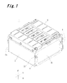
- Fig. 1 is a perspective view of a battery pack according to the present invention
- Fig. 2 is an exploded perspective view of the battery pack shown in Fig. 1 ;
- Fig. 3 is an exploded perspective view of a battery pack assembly
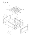
- Fig. 4 is a perspective view of a stack case, endplates, and a stack outer cover
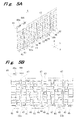
- Fig. 5A is a perspective view of a spacer
- Fig. 5B is a front view of the spacer
- Fig. 6A is a perspective view of two kinds of bottom members
- Fig. 6B is a sectional view of the two kinds of bottom members
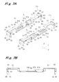
- Fig. 7A is a perspective view of two kinds of inner cover members
- Fig. 7B is a sectional view of the inner cover member
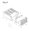
- Fig. 8 is a perspective view showing a state where sets each including a bottom member, single cells, and spacers are accommodated in the stack case;
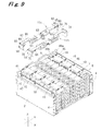
- Fig. 9 is a perspective view showing a state where bus bars and the inner cover members are mounted on the single cells and the spacers accommodate in the stack case;
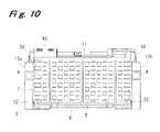
- Fig. 10 is a sectional view of an assembled battery pack
- Fig. 11 is a plan view of the battery pack showing a wiring state of harnesses
- Fig. 12 is a sectional view showing a cooling flow path of the battery pack
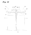
- Fig. 13 is a sectional view showing an insulating structure around a terminal of the single cell.
- Fig. 14 is a plan view showing a state where first and second inner cover members are mounted.
- X and Y axes which intersect with each other at right angles on a horizontal plane and a Z axis which intersects with the X and Y axes at right angles are set as shown in Fig. 1 .
- Directions which are parallel to the X, Y, and Z axes are respectively referred to as an X direction, a Y direction, and a Z direction, respectively.
- Fig. 1 shows a battery pack 1 according to the embodiment of the present invention.
- the battery pack 1 mainly includes a stack case 2, end plates 3a and 3b, assembling shafts 4, a stack outer cover 5, and a battery pack assembly 6.
- the stack case 2 is formed from steel plate.
- the stack case 2 includes a rectangular bottom plate 12 extending in the X and Y directions, and a left wall portion 13a and a right wall portion 13b formed upright, in the Z direction, from both ends of the bottom plate 12 in the Y direction.
- both ends in the X direction and upper ends in the Z direction are opened.
- a central portion of the bottom plate 12 has a projection 14 which is formed slightly higher than the both ends of the Y direction.
- the projection 14 reinforces the bottom plate 12.
- a recess 54 of a later-described bottom member 9 is engaged with the projection 14 such that the recess 54 can move in the X direction.
- Each of the left wall portion 13a and the right wall portion 13b is formed from an outer wall 15 and an inner wall 16.
- Lower ends of the outer walls 15 are integrally formed on the bottom plate 12 such that the lower ends are continuous with the both ends of the bottom plate 12 of the Y direction.
- Lower ends of the inner walls 16 are connected to the bottom plate 12.
- Upper ends 17 of the outer walls 15 and the inner walls 16 are bent into L-shapes in mutually approaching directions and connected to each other.
- Two ribs 18a and 18b extending in the X direction are provided between the outer wall 15 and the inner wall 16 of the left wall portion 13a. Both side ends of the ribs 18a and 18b in the Y direction are connected to the outer wall 15 and the inner wall 16.
- a first refrigerant passage 19 is formed in a space between the outer wall 15 and the inner wall 16 located above the upper rib 18a.
- a second refrigerant passage 20 is formed in a space between the outer wall 15 and the inner wall 16 located below the lower rib 18b.
- a cross section of the first refrigerant passage 19 which is orthogonal to the X direction is formed smaller than a cross section of the second refrigerant passage 20 which is orthogonal to the X direction. Sizes of the first refrigerant passage 19 and the second refrigerant passage 20 may be determined such that more refrigerant flows through portions of the single cells 7 where surface temperature is high, and the sizes are not limited to the shape of the embodiment.
- a third refrigerant passage 21 and a fourth refrigerant passage 22 are formed in the right wall portion 13b by means of ribs 18a and 18b.
- a plurality of first openings 23 which are in communication with the first refrigerant passage 19 are formed in the inner wall 16 of the left wall portion 13a at constant distances from one another in the X direction. The distances are equal to arrangement intervals of later-described spacers 8.
- a plurality of second openings 24 which are in communication with the second refrigerant passage 20 are formed at constant distances from one another in the X direction. The distances are equal to those of the first openings 23. Widths of the first openings 23 and the second openings 24 in the X direction are the same, but lengths thereof in the Z direction are different from each other, and the lengths of the first openings 23 are smaller than those of the second openings 24.
- sizes of areas of the first opening 23 and the second opening 24 may be determined such that more refrigerant flows through portions of the single cells 7 where surface temperature is high, and the sizes are not limited to the shape of this embodiment.
- Third openings 25 and fourth openings 26 which are similar to the first openings 23 and the second openings 24 of the left wall portion 13a are also formed in the inner wall 16 of the right wall portion 13b.
- the end plates 3a and 3b are plate-like members for closing openings in both ends of the stack case 2 of the X direction.
- a first refrigerant inlet 28 which is in communication with the first refrigerant passage 19 and a second refrigerant inlet 29 which is in communication with the second refrigerant passage 20 of the left wall portion 13a of the stack case 2.
- a first refrigerant outlet 30 which is in communication with the third refrigerant passage 21 and a second refrigerant outlet 31 which is in communication with the fourth refrigerant passage 22 of the right wall portion 13b of the stack case 2.
- Projections 32 projecting toward the stack case 2 are provided on edges of the first and second refrigerant inlets 28 and 29 and the first and second refrigerant outlets 30 and 31, and these edges face the stack case 2.
- the projections 32 are inserted into the first and second refrigerant passages 19 and 20 and the third and fourth refrigerant passages 21 and 22 so that cooling media do not leak out from gaps between the stack case 2 and the end plates 3a and 3b.
- slits 33 into which insertion pieces 39 of the later-described stack outer cover 5 are inserted.
- notches 34 for pulling out harnesses are formed in central portions of the upper end surfaces of the end plates 3a and 3b.
- the assembling shafts 4 are round rods inserted between the two ribs 18a and 18b of the stack case 2.
- Each of the assembling shafts 4 includes a central large-diameter portion 35 and small-diameter portions 36 on both ends. Threads on which nuts 37 are mounted are formed in the small-diameter portions 36 on both ends of the shaft 4.
- a length of the central large-diameter portion 35 of the shaft 4 is formed longer than a length of the stack case 2 in the X direction so that even if the nuts 37 are fastened to the small-diameter portions 36 on both ends of the shaft 4 through the end plates 3a and 3b, the stack case 2 is not crushed.
- the stack outer cover 5 is formed from metal plate, more specifically, from steel plate made of conductive material.
- Mounting pieces 38 which are screwed to the upper ends 17 of the stack case 2 are formed on both ends of the stack outer cover 5 in the Y direction by bending the both ends toward the stack case 2 in the Z direction.
- Insertion pieces 39 inserted into the slits 33 of the end plates 3a and 3b are formed on both ends of the stack outer cover 5 in the X direction by bending the both ends toward the end plates 3a and 3b in the Z direction.
- the stack outer cover 5 has a convex portion 40 formed at a central portion of an inner surface thereof.
- the convex portion 40 is formed slightly lower than the both ends of the stack outer cover 5 in the Y direction.
- the convex portion 40 reinforces the stack outer cover 5, and engages with a below-described recess 71 of an inner cover member 11 to hold the inner cover member 11.
- an outer cover 5 is mounted on the stack case 2.
- the outer cover 5 can be replaced by the floor or the seat.
- a member like the outer cover 5 of this embodiment is not necessarily required as long as the single cells 7 accommodated in the stack case 2 can be protected by the later-described inner cover member 11.
- the battery pack assembly 6 includes a plurality of single cells 7, the spacers 8 (the number of which is greater than that of the battery packs 7 by one), bottom members 9 (the number of which is the same as that of the battery packs 7), bus bars 10 (the number of which is smaller than that of the battery packs 7 by one), and the inner cover members 11 (the number of which is the same as that of the battery packs 7).
- the inner cover member 11 is one example of the insulating member of the invention of the present application.
- the inner cover member 11 is located between the outer cover 5 which covers an upper opening of the stack case 2 and surfaces of the single cell 7 where terminals 41 and 42 are provided.
- each of the single cells 7 is a non-aqueous secondary battery such as a lithium-ion battery.
- the single cell 7 has a width in the X direction capable of being accommodated between the left wall portion 13a and the right wall portion 13b of the stack case 2, a depth in the Y direction, and a height in the Z direction.
- the single cell 7 has, on its upper surface, positive and negative electrodes 41 and 42.
- the single cell 7 may literally be a single battery, or may include a unit of a plurality of small batteries arranged in the X direction.
- each of the spacers 8 is molded from synthetic resin.
- the spacer 8 includes an upper sash bar 43 and a lower sash bar 44 extending in the Y direction.
- First convexo-concave portions 45, second convexo-concave portions 46, and straight portions 47 are formed between the upper sash bar 43 and the lower sash bar 44.
- each of the first convexo-concave portions 45 concave portions and convex portions are alternately formed in a corrugated form in the Z direction on a first surface viewed from the X direction, and concave portions and convex portions are also alternately formed in a corrugated form in the Z direction on a second surface which is on a back side of the first surface.
- concave portions and convex portions are alternately formed in a corrugated form on the second convexo-concave portion 46, but the concave portions and convex portions are reversely formed from those of the first convexo-concave portion 45.
- the straight portions 47 connect the upper sash bar 43 and the lower sash bar 44 with each other, extend straightly in the Z direction, and prevent the spacers 8 from extending in the Z direction.
- an insulating wall 48 having a width in the Y direction which is greater than those of the terminals 41 and 42 of the single cell 7 is integrally formed so as to project upward. Since the insulating wall 48 is integrally formed on the spacer 8, it is unnecessary to separately provide the insulating wall 48 as a separate part, and the number of parts is reduced.
- Two engaging holes 49a and 49b are formed in each of the insulating walls 48 such that the engaging holes 49a and 49b are arranged in the Y direction. Engaging projections 65 of the later-described inner cover member 11 are engaged with the engaging holes 49a and 49b.
- a pair of engaging pawls 50a and 50b are formed on both sides of a lower end of the lower sash bar 44 of the spacer 8.
- the engaging pawls 50a and 50b are formed by forming pawls on tip ends of resilient arms, and the engaging pawls 50a and 50b engage with engaging holes 53 of the later-described bottom member 9.
- the bottom member 9 is molded from synthetic resin.
- the bottom member 9 is provided corresponding to each of the single cells 7.
- the bottom member 9 includes a base portion 51 and projecting pieces 52.
- One single cell 7 is placed on an upper surface of the base portion 51.
- the projecting pieces 52 are formed upright in the Z direction, from both ends of the base portion 51 in the Y direction.
- Engaging holes 53 into which the pair of engaging pawls 50a and 50b of the spacer 8 engage are formed in one side end of the base portion 51.
- the concave portion 54 with which the convex portion 14 of the stack case 2 engages is formed on the bottom surface of the base portion 51.
- Long holes 55 for reducing weight and for preventing shrinkage at the time of molding are extensively formed in the base portion 51.
- Each of the projecting pieces 52 is interposed in a gap between the single cell 7 and the left and right wall portions 13a and 13b of the stack case 2, and prevents the single cell 7 from moving in the Y direction.
- bottom members 9a located on both ends of the battery pack assembly 6 in the X direction are formed wider than other bottom members 9.
- the bus bar 10 is made of a conductive plate-like material, and the bus bar 10 electrically connects the positive terminal 41 and the negative terminal 42 of the adjacent single cells 7.
- the inner cover member 11 is molded from synthetic resin.
- the inner cover member 11 is provided corresponding to each of the single cells 7.
- the inner cover member 11 includes two kinds of members, i.e., a first inner cover member 11a and a second inner cover member 11b.
- the inner cover member 11 has substantially the same width as a size of the single cell 7 in its short side direction as viewed from a surface of the single cell 7 where the terminals 41 and 42 are provided, and has substantially the same length as a size of the single cell 7 in its long side direction.
- the width of the inner cover member 11 is equal to a total of a thickness of the spacer 8 and a size of the single cell 7 in its short side direction as viewed from the surface of the single cell 7 where the terminals 41 and 42 are provided.
- the inner cover members 11 are disposed in the short side direction of the single cell with the same pitch as the single cells.
- a length of the inner cover member 11 is greater than a size of the single cell 7 in its long side direction by sizes of later-described projections 58 on both ends.
- the first inner cover member 11a includes a central base portion 56, terminal insulating portions 57 formed higher than the base portion 56 on both sides of the base portion 56, and projections 58 projecting downward along the Z direction from ends of the terminal insulating portions 57.
- a width of the base portion 56 of the first inner cover member 11a is the same as a size of the single cell 7 in its short side direction as viewed from the surface of the single cell 7 where the terminals 41 and 42 are provided.
- a length of the base portion 56 between the left and right terminal insulating portions 57 and 57 of the first inner cover member 11a is the same as the size of the single cell 7 in its long side direction.
- a notch 59 is formed in a central portion of an upper surface of the base portion 56 on one side end in the X direction, and a fixing portion 60 which is a pair of bending arms for fixing a harness is formed on an opposing edge of the notch 59.
- a guide portion 61 is formed on one end of the upper surface of the base portion 56.
- the guide portion 61 includes a first guide portion 61a extending in the Y direction from a position close to one side end toward a center, and a second guide portion 61b extending in the X direction from an end of the first guide portion 61a toward the other side end thereof.
- a guide portion 61 is formed on the other end of the upper surface of the base portion 56.
- the guide portion 61 includes a first guide portion 61a extending in the Y direction from a position close to one side end toward a center, and a second guide portion 61b extending in the X direction from an end of the first guide portion 61a toward the other side end thereof. Openings 62 are formed in both ends of the base portion 56 for reducing weight, reducing material, and preventing molding failure.
- a notch 63 is formed in one side edge of each of the terminal insulating portions 57.
- the notch 63 is formed at such a position that when the first inner cover member 11a is mounted on the single cell 7, the notch 63 is located above the terminals 41 and 42 of the single cell 7 and about halves of the terminals 41 and 42 are exposed. Providing the notch 63, as described later, after mounting the inner cover members 11 are mounted to the single cells 7, a wire for connection to a measurement instrument can be connected to the terminals 41, 42 or the bus bar 10 and can be drawn out from the inner cover member 11.
- An engaging projection 65 is formed on a reinforcing rib 64 provided on the other side edge of the terminal insulating portion 57.
- the engaging projection 65 is opposed to the insulating wall 48 of the spacer 8 and the engaging projection 65 engages with one of the engaging holes 49a and 49b of the insulating wall 48.
- the projection 58 is provided with reinforcing ribs 66 on both side edges in the X direction, and a reinforcing plate 67 which connects the reinforcing ribs 66 to each other to form into a box shape.
- An engaging groove 68 is formed in an upper end of each of the reinforcing ribs 66. Lower ends of both the reinforcing ribs 66 are formed into tapered portions 69 which are tapered downward.
- the second inner cover member 11b is mirror-symmetrical to the first inner cover member 11a on an X-Y plane except for the fixing portion 60, the engaging projection 65, and the engaging groove 68.
- a fixing portion 60 of a base portion 56 of the second inner cover member 11b is formed on the same side edge as the fixing portion 60 of the first inner cover member 11a, but is formed on the opposite side with respect to a center line C in the X direction.
- An engaging projection 65 of a terminal insulating portion 57 of the second inner cover member 11b is formed on a side edge opposite to the engaging projection 65 of the terminal insulating portion 57 of the first inner cover member 11a, and is formed at a location far from the center line C in the X direction.
- An engaging projection 70 which engages with the engaging groove 68 of the first inner cover member 11a is formed on a projection 58 of the second inner cover member 11b.
- the shafts 4 are inserted between the ribs 18a and 18b of the stack case 2, the nuts 32 are mounted on one ends of the shafts 4, the end plate 3a is placed on one end of the stack case 2, and the other end of the stack case 2 is left open.
- the end plate 3a may be mounted after the battery pack assembly 6 is accommodated.
- the engaging pawls 50a and 50b of the lower end of the spacer 8 are engaged with the engaging holes 53 of the bottom member 9 to integrally form the spacer 8 and the bottom member 9, and the single cell 7 is placed on the bottom member 9.
- One set of the spacer 8, the bottom member 9, and the single cell 7 is inserted from the opened end of the stack case 2, the concave portion 54 of the bottom member 9 is engaged with the convex portion 14 of the stack case 2, which is scover toward a depth side of the stack case 2 in the X direction, and it is accommodated in the stack case 2.
- all of other sets of the spacers 8, the bottom members 9, and the single cells 7 are accommodated in the stack case 2.
- the spacers 8 are mounted on both ends of the last bottom member 9a, and the bottom member 9a is accommodated in the stack case 2 with the single cell 7 sandwiched between the two spacers 8 and 8.
- the spacers 8 are disposed such that the insulating walls 48 are alternately disposed on the left side and the right side as viewed from the X direction.
- the insulating walls 48 of the spacers 8 are disposed in a zigzag form from one end single cell to the other end single cell of the battery pack, i.e., in the X direction as viewed from the terminal of the battery pack 1, i.e., from the Z direction.
- the insulating walls 48 of the spacers 8 are not disposed in the zigzag form due to erroneous assembly, if the insulating wall 48 of the erroneously disposed spacer 8 is pulled upward, the engaging pawls 50a and 50b of the spacer 8 are detached from the engaging holes 53 of the bottom member 9. Therefore, only the spacer 8 can be pulled out and disposed in the correct direction. Since the insulating wall 48 is integrally formed on the spacer 8, it is unnecessary to separately mount the insulating wall 48, a structure around the terminals 41 and 42 is simplified, and since only the spacer 8 needs to be mounted, it is easy to assemble.
- the end plate 3b is placed on the opened end of the stack case 2, and the nuts 32 are mounted on and fastened to the shafts 4 which project from the end plate 3b.
- the large-diameter portion 35 of the shaft 4 is longer than the length of the stack case 2, even if the nuts 32 are fastened, the length of the end plate 2 in the X direction does not become shorter than the length of the large-diameter portion 35 of the shaft 4, and the stack case 2 is not crushed.
- bus bars 10 are mounted on the electrodes 41 and 42 of the adjacent single cells 7, and all of the single cells 7 are connected to one another in series.
- the inner cover members 11a and 11b are mounted on the single cells 7.
- the first and second inner cover members 11a and 11b are alternately mounted. That is, there is employed such a design that the notch 63 and the notch 63 are opposed to each other to face the bus bar 10 on the side of one end where the adjacent two single cells 7 are connected to each other through the bus bar 10, and the engaging projection 65 and the engaging projection 65 are opposed to each other on the side of other end where the two single cells 7 are not connected through the bus bar 10.
- the engaging projection 70 of the second inner cover member 11b is engaged with the engaging groove 68 of the first inner cover member 11a so that the engaging groove 68 and the engaging projection 70 do not separate from each other.
- Fig. 13 shows an insulating structure around the terminals 41 and 42 of the adjacent single cells 7.
- the insulating wall 48 of the spacer 8 is located between the terminals 41 and 42.
- the terminal insulating portions 57 of the first and second inner cover members 11a and 11b are mounted on the insulating wall 48.
- a long creeping distance from the terminal 41 of the left single cell 7 to the terminal 42 of the right single cell 7 in Fig. 13 is secured by the insulating wall 48 and the terminal insulating portion 57, and the terminals 41 and 42 of the adjacent single cells 7 are sufficiently electrically insulated from each other.
- first and second inner cover members 11a and 11b are mounted on the spacer 8, positions of the inner cover members 11a and 11b and the spacer 8 with respect to the single cell are reliably held against vibration caused when the battery pack is mounted in a vehicle for example. As a result, it is possible to avoid a case where insulation properties of the first and second inner cover members 11a and 11b kept by the terminal insulating portions 57 are deteriorated due to displacement of the first and second inner cover members 11a and 11b with respect to the single cell 7.
- a resilient member such as a leaf spring may be interposed between the end plates 3a and 3b and the spacers 8 opposed thereto.
- voltage-detecting harnesses are connected to the terminals 41 and 42 through the notch 63 of the terminal insulating portion 57 (The voltage-detecting harnesses can also be connected to the bus bar 10 through the notch 63).
- the harnesses are wired toward a center along a guide groove formed by the first guide portions 61a of the adjacent first and second inner cover members 11a and 11b, and the harnesses are bent 90° at the center. Further, the harnesses are wired along the guide groove formed by the adjacent second guide portions 61b, and the harnesses are pulled outside of the stack case 2 through the notches 34 of the end plates 3a and 3b while being appropriately fixed to the fixing portion 60.
- the stack outer cover 5 is placed on the upper opening of the stack case 2, the mounting pieces 38 of the stack outer cover 5 are superposed on the upper ends 17 on both ends of the stack case 2, the insertion pieces 39 of the stack outer cover 5 are inserted into the slits 33 of the end plates 3a and 3b, and mounted by being threadedly engaged with bolts.
- the convex portion 40 of the stack outer cover 5 is fitted into the concave portion 71 formed by steps between the base portions 56 of the first and second inner cover members 11a and 11b and the terminal insulating portions 57 on both sides thereof, and the first and second inner cover members 11a and 11b are pressed against the single cell 7.
- the assembling of the battery pack 1 is completed in the above-described manner, but the assembling procedure is not limited thereto. All of the single cells 7, the spacers 8, and the bottom members 9 may be assembled outside of the stack case 2, and the assembly 6 may be accommodated in the stack case 2 at one time.
- a refrigerant introduced into the first refrigerant passage 19 and the second refrigerant passage 20 of the left wall portion 13a of the stack case 2 respectively flows from the first and second openings 23 and 24 of the inner wall 16 into the first and second convexo-concave portions 45 and 46 of the spacer 8. While the refrigerant passes through the first and second convexo-concave portions 45 and 46, the refrigerant cools the adjacent single cells 7.
- the refrigerant which passes through all of the first and second convexo-concave portions 45 and 46 of the spacer 8 passes through the third opening 25 and the fourth opening 26 of the right wall portion 13b of the stack case 2, and flows out into the third refrigerant passage 21 and the fourth refrigerant passage 22.
- the present invention is not limited to the embodiment and can variously be modified.
- the inner cover members 11a and 11b are mounted on the spacer 8 by engaging the engaging projections 65 of the inner cover members 11a and 11b with the engaging holes 49a and 49b formed in the insulating wall 48 provided to the spacer 8.
- a spacer 8 in which engaging holes are provided to inner cover members 11a and 11b may be provided with an engaging projection.
- the inner cover members 11a and 11b may be mounted on portions of the spacer 8 other than the insulating wall 48.
- the insulating wall 48 is not necessarily integrally formed on the spacer 8.
- the insulating wall may be a member which is separate from the spacer 8, and such a separate insulating wall may be mounted on the spacer 8.
- the inner cover members 11a and 11b may not be necessarily provided with notch 63 formed in the terminal insulating portion 57.
- the outer cover 5 can be omitted.
Landscapes
- Chemical & Material Sciences (AREA)
- Chemical Kinetics & Catalysis (AREA)
- Electrochemistry (AREA)
- General Chemical & Material Sciences (AREA)
- Engineering & Computer Science (AREA)
- Manufacturing & Machinery (AREA)
- Inorganic Chemistry (AREA)
- Battery Mounting, Suspending (AREA)
- Connection Of Batteries Or Terminals (AREA)
Abstract
Description
- This application claims priority from Japanese Patent Applications Nos.
2011-214403 2012-213023 - The present invention relates to a battery pack having a plurality of single cells combined together, more particularly, to a structure of an insulating member arranged between terminals of adjacent single cells.
- A battery pack having a plurality of single cells combined together as disclosed in
JP 2010-272251 A JP 2011-76967 A - The battery pack includes a large number of single cells, but the number of single cells is changed depending on the intended use. In such battery pack, newly designing and producing the insulating member every time when the number of single cells is changed causes complexity of design operation, necessity for new mold, and necessity for changes in assembling operation, as well as necessity for inventories of a large number of parts.
- It is an object of the present invention to easily prepare insulating members even if the number of single cells is changed, and to provide a battery pack that the single cells can be packed together with insulating members.
- The present invention provides a battery pack comprising, a plurality of single cells, a case which accommodates the plurality of single cells arranged in line, and insulating members each provided for each of the single cells, the insulating members being disposed on a surface of the single cells where terminals are provided. Preferably, each of the insulating members includes a terminal insulating portion for covering the terminal of the single cell. Further, it is preferable that the battery pack comprises spacers disposed between the adjacent single cells. Furthermore, it is preferable that the insulating members are attached to the spacer.
- Preferably, the spacer includes an insulating wall disposed between the terminals of the adjacent single cells not connected with each other, and wherein the insulating member is attached to the insulating wall. This arrangement achieves that insulation properties between the terminals of the adjacent single cells can be effectively secured by the cover member and the insulating wall of the spacer.
- According to one aspect, the insulating wall is provided with a pair of engaging holes. An engaging projection is provided on the insulating members for one of the single cells opposed to each other across the insulating wall, the engaging projection being engaged with the one of the pair of engaging holes. Another engaging projection is provided on the insulating members for the other of the single cells opposed to each other across the insulating wall, the engaging projection being engaged with the other of the pair of engaging holes. This arrangement achieves that the cover member covering each of the single cells can easily be mounted on the insulating wall of the spacer. Further, it is possible to avoid erroneous assembly of the adjacent cover members.
- It is preferable that a notch is provided in the terminal insulating portion of the insulating member, the notch facing a bus bar through which the terminals of the adjacent single cells are connected. Using the space of the notch, it is possible to pull out a wire connected to the terminal or the bus bar.
- Preferably, the insulating member includes an engaging portion through which the adjacent insulating members are engaged with each other. This According to this configuration, it is possible to sequentially assemble the insulating members such that they do not separate from each other.
- The insulating member may include projection inserted between the single cell and the case. The projection can more reliably hold a position of the single cell in the case.
- An outer cover for covering the insulating member may be provided.
- The insulating member may include a fixing portion for fixing a harness connected to the terminal of each of the single cells.
- The insulating member may include a base portion which is opposed to the surface between the terminals of the single cell and at both ends of which the terminal insulating portions are provided.
- According to the present invention, the insulating member is disposed on a surface of each of the single cell where the terminals are provided, and the insulating member is provided for each of the single cells. Therefore, even if the number of single cells used for a battery pack is changed, it is only necessary to adjust the number of lid members in accordance with the number of single cells, and it is unnecessary to newly produce an exclusive insulating member.
-
Fig. 1 is a perspective view of a battery pack according to the present invention; -
Fig. 2 is an exploded perspective view of the battery pack shown inFig. 1 ; -
Fig. 3 is an exploded perspective view of a battery pack assembly; -
Fig. 4 is a perspective view of a stack case, endplates, and a stack outer cover; -
Fig. 5A is a perspective view of a spacer; -
Fig. 5B is a front view of the spacer; -
Fig. 6A is a perspective view of two kinds of bottom members; -
Fig. 6B is a sectional view of the two kinds of bottom members; -
Fig. 7A is a perspective view of two kinds of inner cover members; -
Fig. 7B is a sectional view of the inner cover member; -
Fig. 8 is a perspective view showing a state where sets each including a bottom member, single cells, and spacers are accommodated in the stack case; -
Fig. 9 is a perspective view showing a state where bus bars and the inner cover members are mounted on the single cells and the spacers accommodate in the stack case; -
Fig. 10 is a sectional view of an assembled battery pack; -
Fig. 11 is a plan view of the battery pack showing a wiring state of harnesses; -
Fig. 12 is a sectional view showing a cooling flow path of the battery pack; -
Fig. 13 is a sectional view showing an insulating structure around a terminal of the single cell; and -
Fig. 14 is a plan view showing a state where first and second inner cover members are mounted. - An embodiment of the present invention will be described below with reference to the accompanying drawings. Herein, for convenience sake of description, X and Y axes which intersect with each other at right angles on a horizontal plane and a Z axis which intersects with the X and Y axes at right angles are set as shown in
Fig. 1 . Directions which are parallel to the X, Y, and Z axes are respectively referred to as an X direction, a Y direction, and a Z direction, respectively. -
Fig. 1 shows abattery pack 1 according to the embodiment of the present invention. As shown inFig. 2 , thebattery pack 1 mainly includes astack case 2,end plates shafts 4, a stackouter cover 5, and abattery pack assembly 6. - As shown in
Fig. 4 , thestack case 2 is formed from steel plate. Thestack case 2 includes arectangular bottom plate 12 extending in the X and Y directions, and aleft wall portion 13a and aright wall portion 13b formed upright, in the Z direction, from both ends of thebottom plate 12 in the Y direction. In thestack case 2, both ends in the X direction and upper ends in the Z direction are opened. - A central portion of the
bottom plate 12 has aprojection 14 which is formed slightly higher than the both ends of the Y direction. Theprojection 14 reinforces thebottom plate 12. Arecess 54 of a later-describedbottom member 9 is engaged with theprojection 14 such that therecess 54 can move in the X direction. - Each of the
left wall portion 13a and theright wall portion 13b is formed from anouter wall 15 and aninner wall 16. Lower ends of theouter walls 15 are integrally formed on thebottom plate 12 such that the lower ends are continuous with the both ends of thebottom plate 12 of the Y direction. Lower ends of theinner walls 16 are connected to thebottom plate 12. Upper ends 17 of theouter walls 15 and theinner walls 16 are bent into L-shapes in mutually approaching directions and connected to each other. - Two
ribs outer wall 15 and theinner wall 16 of theleft wall portion 13a. Both side ends of theribs outer wall 15 and theinner wall 16. Afirst refrigerant passage 19 is formed in a space between theouter wall 15 and theinner wall 16 located above theupper rib 18a. Asecond refrigerant passage 20 is formed in a space between theouter wall 15 and theinner wall 16 located below thelower rib 18b. A cross section of the firstrefrigerant passage 19 which is orthogonal to the X direction is formed smaller than a cross section of the secondrefrigerant passage 20 which is orthogonal to the X direction. Sizes of the firstrefrigerant passage 19 and the secondrefrigerant passage 20 may be determined such that more refrigerant flows through portions of thesingle cells 7 where surface temperature is high, and the sizes are not limited to the shape of the embodiment. - Similarly, a third
refrigerant passage 21 and a fourthrefrigerant passage 22 are formed in theright wall portion 13b by means ofribs - A plurality of
first openings 23 which are in communication with the firstrefrigerant passage 19 are formed in theinner wall 16 of theleft wall portion 13a at constant distances from one another in the X direction. The distances are equal to arrangement intervals of later-describedspacers 8. Similarly, a plurality ofsecond openings 24 which are in communication with the secondrefrigerant passage 20 are formed at constant distances from one another in the X direction. The distances are equal to those of thefirst openings 23. Widths of thefirst openings 23 and thesecond openings 24 in the X direction are the same, but lengths thereof in the Z direction are different from each other, and the lengths of thefirst openings 23 are smaller than those of thesecond openings 24. Similarly to the firstrefrigerant passage 19 and the secondrefrigerant passage 20, sizes of areas of thefirst opening 23 and thesecond opening 24 may be determined such that more refrigerant flows through portions of thesingle cells 7 where surface temperature is high, and the sizes are not limited to the shape of this embodiment. -
Third openings 25 andfourth openings 26 which are similar to thefirst openings 23 and thesecond openings 24 of theleft wall portion 13a are also formed in theinner wall 16 of theright wall portion 13b. -
Nuts 27 for fixing the stackouter cover 5 through screws are fixed to upper ends 17 of thewall portions - The
end plates stack case 2 of the X direction. InFig. 4 , in one end of theleft end plate 3a, there are formed a firstrefrigerant inlet 28 which is in communication with the firstrefrigerant passage 19 and a secondrefrigerant inlet 29 which is in communication with the secondrefrigerant passage 20 of theleft wall portion 13a of thestack case 2. Similarly, in one end of theright end plate 3b, there are formed a firstrefrigerant outlet 30 which is in communication with the thirdrefrigerant passage 21 and a secondrefrigerant outlet 31 which is in communication with the fourthrefrigerant passage 22 of theright wall portion 13b of thestack case 2.Projections 32 projecting toward thestack case 2 are provided on edges of the first and secondrefrigerant inlets refrigerant outlets stack case 2. Theprojections 32 are inserted into the first and secondrefrigerant passages refrigerant passages stack case 2 and theend plates end plates slits 33 into whichinsertion pieces 39 of the later-described stackouter cover 5 are inserted. Further, in central portions of the upper end surfaces of theend plates notches 34 for pulling out harnesses are formed. - As shown in
Fig. 2 , the assemblingshafts 4 are round rods inserted between the tworibs stack case 2. Each of the assemblingshafts 4 includes a central large-diameter portion 35 and small-diameter portions 36 on both ends. Threads on which nuts 37 are mounted are formed in the small-diameter portions 36 on both ends of theshaft 4. A length of the central large-diameter portion 35 of theshaft 4 is formed longer than a length of thestack case 2 in the X direction so that even if the nuts 37 are fastened to the small-diameter portions 36 on both ends of theshaft 4 through theend plates stack case 2 is not crushed. - Referring back to
Fig. 4 , the stackouter cover 5 is formed from metal plate, more specifically, from steel plate made of conductive material. Mountingpieces 38 which are screwed to the upper ends 17 of thestack case 2 are formed on both ends of the stackouter cover 5 in the Y direction by bending the both ends toward thestack case 2 in the Z direction.Insertion pieces 39 inserted into theslits 33 of theend plates outer cover 5 in the X direction by bending the both ends toward theend plates outer cover 5 has aconvex portion 40 formed at a central portion of an inner surface thereof. Theconvex portion 40 is formed slightly lower than the both ends of the stackouter cover 5 in the Y direction. Theconvex portion 40 reinforces the stackouter cover 5, and engages with a below-described recess 71 of aninner cover member 11 to hold theinner cover member 11. - In this embodiment, an
outer cover 5 is mounted on thestack case 2. However, if an upper portion of thebattery pack assembly 6 is closed with a floor or a seat of a vehicle for example, theouter cover 5 can be replaced by the floor or the seat. In other words, a member like theouter cover 5 of this embodiment is not necessarily required as long as thesingle cells 7 accommodated in thestack case 2 can be protected by the later-describedinner cover member 11. - In
Fig. 3 , thebattery pack assembly 6 includes a plurality ofsingle cells 7, the spacers 8 (the number of which is greater than that of the battery packs 7 by one), bottom members 9 (the number of which is the same as that of the battery packs 7), bus bars 10 (the number of which is smaller than that of the battery packs 7 by one), and the inner cover members 11 (the number of which is the same as that of the battery packs 7). Theinner cover member 11 is one example of the insulating member of the invention of the present application. Theinner cover member 11 is located between theouter cover 5 which covers an upper opening of thestack case 2 and surfaces of thesingle cell 7 whereterminals - In this embodiment, each of the
single cells 7 is a non-aqueous secondary battery such as a lithium-ion battery. Thesingle cell 7 has a width in the X direction capable of being accommodated between theleft wall portion 13a and theright wall portion 13b of thestack case 2, a depth in the Y direction, and a height in the Z direction. Thesingle cell 7 has, on its upper surface, positive andnegative electrodes single cell 7 may literally be a single battery, or may include a unit of a plurality of small batteries arranged in the X direction. - As shown in
Figs. 5A and 5B , each of thespacers 8 is molded from synthetic resin. Thespacer 8 includes anupper sash bar 43 and alower sash bar 44 extending in the Y direction. First convexo-concave portions 45, second convexo-concave portions 46, andstraight portions 47 are formed between theupper sash bar 43 and thelower sash bar 44. - In each of the first convexo-
concave portions 45, concave portions and convex portions are alternately formed in a corrugated form in the Z direction on a first surface viewed from the X direction, and concave portions and convex portions are also alternately formed in a corrugated form in the Z direction on a second surface which is on a back side of the first surface. Similarly to the first convexo-concave portion 45, concave portions and convex portions are alternately formed in a corrugated form on the second convexo-concave portion 46, but the concave portions and convex portions are reversely formed from those of the first convexo-concave portion 45. Thestraight portions 47 connect theupper sash bar 43 and thelower sash bar 44 with each other, extend straightly in the Z direction, and prevent thespacers 8 from extending in the Z direction. - On an upper end of the
upper sash bar 43 of each of thespacers 8 at a location close to one end of the upper end of theupper sash bar 43, an insulatingwall 48 having a width in the Y direction which is greater than those of theterminals single cell 7 is integrally formed so as to project upward. Since the insulatingwall 48 is integrally formed on thespacer 8, it is unnecessary to separately provide the insulatingwall 48 as a separate part, and the number of parts is reduced. Two engagingholes walls 48 such that the engagingholes projections 65 of the later-describedinner cover member 11 are engaged with the engagingholes - A pair of engaging
pawls lower sash bar 44 of thespacer 8. The engagingpawls engaging pawls holes 53 of the later-describedbottom member 9. - As shown in
Figs. 6A and 6B , thebottom member 9 is molded from synthetic resin. Thebottom member 9 is provided corresponding to each of thesingle cells 7. Thebottom member 9 includes abase portion 51 and projectingpieces 52. Onesingle cell 7 is placed on an upper surface of thebase portion 51. The projectingpieces 52 are formed upright in the Z direction, from both ends of thebase portion 51 in the Y direction. - Engaging
holes 53 into which the pair of engagingpawls spacer 8 engage are formed in one side end of thebase portion 51. Theconcave portion 54 with which theconvex portion 14 of thestack case 2 engages is formed on the bottom surface of thebase portion 51. Long holes 55 for reducing weight and for preventing shrinkage at the time of molding are extensively formed in thebase portion 51. Each of the projectingpieces 52 is interposed in a gap between thesingle cell 7 and the left andright wall portions stack case 2, and prevents thesingle cell 7 from moving in the Y direction. - Since engaging
holes 53 are formed in both side ends of thebase portion 51 such that the twospacers 8 are mounted,bottom members 9a located on both ends of thebattery pack assembly 6 in the X direction are formed wider than otherbottom members 9. - Referring back to
Fig. 3 , thebus bar 10 is made of a conductive plate-like material, and thebus bar 10 electrically connects thepositive terminal 41 and thenegative terminal 42 of the adjacentsingle cells 7. - As shown in
Figs. 7A and 7B , theinner cover member 11 is molded from synthetic resin. Theinner cover member 11 is provided corresponding to each of thesingle cells 7. Theinner cover member 11 includes two kinds of members, i.e., a firstinner cover member 11a and a secondinner cover member 11b. Theinner cover member 11 has substantially the same width as a size of thesingle cell 7 in its short side direction as viewed from a surface of thesingle cell 7 where theterminals single cell 7 in its long side direction. More specifically, the width of theinner cover member 11 is equal to a total of a thickness of thespacer 8 and a size of thesingle cell 7 in its short side direction as viewed from the surface of thesingle cell 7 where theterminals inner cover members 11 are disposed in the short side direction of the single cell with the same pitch as the single cells. A length of theinner cover member 11 is greater than a size of thesingle cell 7 in its long side direction by sizes of later-describedprojections 58 on both ends. - The first
inner cover member 11a includes acentral base portion 56, terminal insulatingportions 57 formed higher than thebase portion 56 on both sides of thebase portion 56, andprojections 58 projecting downward along the Z direction from ends of the terminal insulatingportions 57. A width of thebase portion 56 of the firstinner cover member 11a is the same as a size of thesingle cell 7 in its short side direction as viewed from the surface of thesingle cell 7 where theterminals base portion 56 between the left and right terminal insulatingportions inner cover member 11a is the same as the size of thesingle cell 7 in its long side direction. - A
notch 59 is formed in a central portion of an upper surface of thebase portion 56 on one side end in the X direction, and a fixingportion 60 which is a pair of bending arms for fixing a harness is formed on an opposing edge of thenotch 59. Aguide portion 61 is formed on one end of the upper surface of thebase portion 56. Theguide portion 61 includes afirst guide portion 61a extending in the Y direction from a position close to one side end toward a center, and asecond guide portion 61b extending in the X direction from an end of thefirst guide portion 61a toward the other side end thereof. Similarly, aguide portion 61 is formed on the other end of the upper surface of thebase portion 56. Theguide portion 61 includes afirst guide portion 61a extending in the Y direction from a position close to one side end toward a center, and asecond guide portion 61b extending in the X direction from an end of thefirst guide portion 61a toward the other side end thereof.Openings 62 are formed in both ends of thebase portion 56 for reducing weight, reducing material, and preventing molding failure. - A
notch 63 is formed in one side edge of each of the terminal insulatingportions 57. Thenotch 63 is formed at such a position that when the firstinner cover member 11a is mounted on thesingle cell 7, thenotch 63 is located above theterminals single cell 7 and about halves of theterminals notch 63, as described later, after mounting theinner cover members 11 are mounted to thesingle cells 7, a wire for connection to a measurement instrument can be connected to theterminals bus bar 10 and can be drawn out from theinner cover member 11. - An engaging
projection 65 is formed on a reinforcingrib 64 provided on the other side edge of the terminal insulatingportion 57. The engagingprojection 65 is opposed to the insulatingwall 48 of thespacer 8 and the engagingprojection 65 engages with one of the engagingholes wall 48. - The
projection 58 is provided with reinforcingribs 66 on both side edges in the X direction, and a reinforcingplate 67 which connects the reinforcingribs 66 to each other to form into a box shape. An engaginggroove 68 is formed in an upper end of each of the reinforcingribs 66. Lower ends of both the reinforcingribs 66 are formed into taperedportions 69 which are tapered downward. - The second
inner cover member 11b is mirror-symmetrical to the firstinner cover member 11a on an X-Y plane except for the fixingportion 60, the engagingprojection 65, and the engaginggroove 68. A fixingportion 60 of abase portion 56 of the secondinner cover member 11b is formed on the same side edge as the fixingportion 60 of the firstinner cover member 11a, but is formed on the opposite side with respect to a center line C in the X direction. An engagingprojection 65 of a terminal insulatingportion 57 of the secondinner cover member 11b is formed on a side edge opposite to the engagingprojection 65 of the terminal insulatingportion 57 of the firstinner cover member 11a, and is formed at a location far from the center line C in the X direction. An engagingprojection 70 which engages with the engaginggroove 68 of the firstinner cover member 11a is formed on aprojection 58 of the secondinner cover member 11b. - Next, an assembling procedure of the
battery pack 1 having the above configuration will be described. - As shown in
Fig. 8 , theshafts 4 are inserted between theribs stack case 2, the nuts 32 are mounted on one ends of theshafts 4, theend plate 3a is placed on one end of thestack case 2, and the other end of thestack case 2 is left open. Theend plate 3a may be mounted after thebattery pack assembly 6 is accommodated. - Next, the engaging
pawls spacer 8 are engaged with the engagingholes 53 of thebottom member 9 to integrally form thespacer 8 and thebottom member 9, and thesingle cell 7 is placed on thebottom member 9. One set of thespacer 8, thebottom member 9, and thesingle cell 7 is inserted from the opened end of thestack case 2, theconcave portion 54 of thebottom member 9 is engaged with theconvex portion 14 of thestack case 2, which is scover toward a depth side of thestack case 2 in the X direction, and it is accommodated in thestack case 2. Similarly, all of other sets of thespacers 8, thebottom members 9, and thesingle cells 7 are accommodated in thestack case 2. Thespacers 8 are mounted on both ends of thelast bottom member 9a, and thebottom member 9a is accommodated in thestack case 2 with thesingle cell 7 sandwiched between the twospacers spacers 8 are disposed such that the insulatingwalls 48 are alternately disposed on the left side and the right side as viewed from the X direction. According to this configuration, the insulatingwalls 48 of thespacers 8 are disposed in a zigzag form from one end single cell to the other end single cell of the battery pack, i.e., in the X direction as viewed from the terminal of thebattery pack 1, i.e., from the Z direction. - When the insulating
walls 48 of thespacers 8 are not disposed in the zigzag form due to erroneous assembly, if the insulatingwall 48 of the erroneously disposedspacer 8 is pulled upward, the engagingpawls spacer 8 are detached from the engagingholes 53 of thebottom member 9. Therefore, only thespacer 8 can be pulled out and disposed in the correct direction. Since the insulatingwall 48 is integrally formed on thespacer 8, it is unnecessary to separately mount the insulatingwall 48, a structure around theterminals spacer 8 needs to be mounted, it is easy to assemble. - After all of the
spacers 8, thebottom members single cells 7 are accommodated in thestack case 2, theend plate 3b is placed on the opened end of thestack case 2, and the nuts 32 are mounted on and fastened to theshafts 4 which project from theend plate 3b. At this time, since the large-diameter portion 35 of theshaft 4 is longer than the length of thestack case 2, even if the nuts 32 are fastened, the length of theend plate 2 in the X direction does not become shorter than the length of the large-diameter portion 35 of theshaft 4, and thestack case 2 is not crushed. - Next, as shown in
Fig. 9 , bus bars 10 are mounted on theelectrodes single cells 7, and all of thesingle cells 7 are connected to one another in series. - Next, the
inner cover members single cells 7. At this time, the first and secondinner cover members notch 63 and thenotch 63 are opposed to each other to face thebus bar 10 on the side of one end where the adjacent twosingle cells 7 are connected to each other through thebus bar 10, and the engagingprojection 65 and the engagingprojection 65 are opposed to each other on the side of other end where the twosingle cells 7 are not connected through thebus bar 10. The engagingprojection 70 of the secondinner cover member 11b is engaged with the engaginggroove 68 of the firstinner cover member 11a so that the engaginggroove 68 and the engagingprojection 70 do not separate from each other. - When the
inner cover members single cells 7, the engagingprojection 65 of the firstinner cover member 11a is engaged with one of the adjacent engagingholes 49a of thespacer 8, and the engagingprojection 65 of the secondinner cover member 11b is engaged with the other of the adjacent engagingholes 49b of thespacer 8. By engaging the engagingprojections 65 with the engagingholes inner cover members spacer 8. As shown inFig. 14 , even if an attempt is made to mount the secondinner cover member 11b in a left-right reversal manner, since the engagingprojection 65 of the firstinner cover member 11a is already engaged with the engaginghole 49a with which the engagingprojection 65 of the secondinner cover member 11b is to be engaged, the secondinner cover member 11b cannot be mounted. Further, even if an attempt is made to mount another firstinner cover member 11a beside the firstinner cover member 11a which is already mounted, since the engagingprojection 65 which should be engaged with the engagingholes wall 48 is located on the opposite side, the firstinner cover member 11a cannot be mounted. According to this configuration, erroneous assembly of theinner cover members -
Fig. 13 shows an insulating structure around theterminals single cells 7. The insulatingwall 48 of thespacer 8 is located between theterminals projections 65 with the engagingholes portions 57 of the first and secondinner cover members wall 48. Hence, a long creeping distance from theterminal 41 of the leftsingle cell 7 to theterminal 42 of the rightsingle cell 7 inFig. 13 is secured by the insulatingwall 48 and the terminal insulatingportion 57, and theterminals single cells 7 are sufficiently electrically insulated from each other. Further, since the first and secondinner cover members spacer 8, positions of theinner cover members spacer 8 with respect to the single cell are reliably held against vibration caused when the battery pack is mounted in a vehicle for example. As a result, it is possible to avoid a case where insulation properties of the first and secondinner cover members portions 57 are deteriorated due to displacement of the first and secondinner cover members single cell 7. - As shown in
Fig. 10 , since theprojections 58 of the first and secondinner cover members wall portions stack case 2 and thesingle cell 7, deviation of thesingle cell 7 in the Y direction is prevented. To prevent the deviation of thesingle cell 7 in the X direction, a resilient member such as a leaf spring may be interposed between theend plates spacers 8 opposed thereto. - Next, as shown in
Fig. 11 , voltage-detecting harnesses are connected to theterminals notch 63 of the terminal insulating portion 57 (The voltage-detecting harnesses can also be connected to thebus bar 10 through the notch 63). The harnesses are wired toward a center along a guide groove formed by thefirst guide portions 61a of the adjacent first and secondinner cover members second guide portions 61b, and the harnesses are pulled outside of thestack case 2 through thenotches 34 of theend plates portion 60. - After the wiring is completed, the stack
outer cover 5 is placed on the upper opening of thestack case 2, the mountingpieces 38 of the stackouter cover 5 are superposed on the upper ends 17 on both ends of thestack case 2, theinsertion pieces 39 of the stackouter cover 5 are inserted into theslits 33 of theend plates convex portion 40 of the stackouter cover 5 is fitted into the concave portion 71 formed by steps between thebase portions 56 of the first and secondinner cover members portions 57 on both sides thereof, and the first and secondinner cover members single cell 7. - The assembling of the
battery pack 1 is completed in the above-described manner, but the assembling procedure is not limited thereto. All of thesingle cells 7, thespacers 8, and thebottom members 9 may be assembled outside of thestack case 2, and theassembly 6 may be accommodated in thestack case 2 at one time. - Next, an operation of the
battery pack 1 will be described. - As shown in
Fig. 12 , a refrigerant introduced into the firstrefrigerant passage 19 and the secondrefrigerant passage 20 of theleft wall portion 13a of thestack case 2 respectively flows from the first andsecond openings inner wall 16 into the first and second convexo-concave portions spacer 8. While the refrigerant passes through the first and second convexo-concave portions single cells 7. The refrigerant which passes through all of the first and second convexo-concave portions spacer 8 passes through thethird opening 25 and thefourth opening 26 of theright wall portion 13b of thestack case 2, and flows out into the thirdrefrigerant passage 21 and the fourthrefrigerant passage 22. - The present invention is not limited to the embodiment and can variously be modified. For example, in the embodiment, the
inner cover members spacer 8 by engaging the engagingprojections 65 of theinner cover members holes wall 48 provided to thespacer 8. Alternatively, aspacer 8 in which engaging holes are provided toinner cover members inner cover members spacer 8 other than the insulatingwall 48. The insulatingwall 48 is not necessarily integrally formed on thespacer 8. The insulating wall may be a member which is separate from thespacer 8, and such a separate insulating wall may be mounted on thespacer 8. Further, theinner cover members notch 63 formed in the terminal insulatingportion 57. Furthermore, theouter cover 5 can be omitted.
Claims (12)
- A battery pack comprising:a plurality of single cells;a case which accommodates the plurality of single cells arranged in line; andinsulating members each provided for each of the single cells, the insulating members being disposed on a surface of the single cells where terminals are provided.
- The battery pack according to claim 1, wherein each of the insulating members includes a terminal insulating portion for covering the terminal of the single cell.
- The battery pack according to claim 2, further comprising spacers disposed between the adjacent single cells.
- The battery pack according to claim 3, wherein the insulating members is attached to the spacer.
- The battery pack according to claim 4, wherein the spacer includes an insulating wall disposed between the terminals of the adjacent single cells not connected with each other, and
wherein the insulating member is attached to the insulating wall. - The battery pack according to claim 5, wherein the insulating wall is provided with a pair of engaging holes,
wherein an engaging projection is provided on the insulating members for one of the single cells opposed to each other across the insulating wall, the engaging projection being engaged with the one of the pair of engaging holes, and
wherein another engaging projection is provided on the insulating members for the other of the single cells opposed to each other across the insulating wall, the engaging projection being engaged with the other of the pair of engaging holes. - The battery pack according to any one of claims 1 to 6, wherein a notch is provided in the terminal insulating portion of the insulating member, the notch facing a bus bar through which the terminals of the adjacent single cells are connected.
- The battery pack according to any one of claims 1 to 7, wherein the insulating member includes an engaging portion through which the adjacent insulating members are engaged with each other.
- The battery pack according to any one of claims 1 to 8, wherein the insulating member includes projection inserted between the single cell and the case.
- The battery pack according to any one of claims 1 to 9, further comprising an outer cover for covering the insulating member.
- The battery pack according to any one of claims 1 to 10, wherein the insulating member includes a fixing portion for fixing a harness connected to the terminal of each of the single cells.
- The battery pack according to any one of claims 2 to 6, wherein the insulating member includes a base portion which is opposed to the surface between the terminals of the single cell and at both ends of which the terminal insulating portions are provided.
Applications Claiming Priority (2)
| Application Number | Priority Date | Filing Date | Title |
|---|---|---|---|
| JP2011214403 | 2011-09-29 | ||
| JP2012213023A JP6079097B2 (en) | 2011-09-29 | 2012-09-26 | Assembled battery |
Publications (2)
| Publication Number | Publication Date |
|---|---|
| EP2575193A1 true EP2575193A1 (en) | 2013-04-03 |
| EP2575193B1 EP2575193B1 (en) | 2022-10-26 |
Family
ID=47018833
Family Applications (1)
| Application Number | Title | Priority Date | Filing Date |
|---|---|---|---|
| EP12186537.2A Active EP2575193B1 (en) | 2011-09-29 | 2012-09-28 | Battery pack |
Country Status (5)
| Country | Link |
|---|---|
| US (1) | US9028996B2 (en) |
| EP (1) | EP2575193B1 (en) |
| JP (1) | JP6079097B2 (en) |
| KR (1) | KR102017089B1 (en) |
| CN (1) | CN103035875B (en) |
Cited By (4)
| Publication number | Priority date | Publication date | Assignee | Title |
|---|---|---|---|---|
| EP2843725A1 (en) * | 2013-09-03 | 2015-03-04 | Samsung SDI Co., Ltd. | Battery Pack |
| EP3159954A4 (en) * | 2015-08-12 | 2018-01-03 | China Aviation Lithium Battery Co., Ltd. | Insulation motherboard, insulation wire harness motherboard assembly and battery module |
| EP3944401A1 (en) * | 2020-07-13 | 2022-01-26 | ABB Schweiz AG | Cooled battery module |
| EP4123811A4 (en) * | 2020-03-18 | 2023-10-25 | GS Yuasa International Ltd. | Power storage device |
Families Citing this family (41)
| Publication number | Priority date | Publication date | Assignee | Title |
|---|---|---|---|---|
| US9722334B2 (en) * | 2010-04-07 | 2017-08-01 | Black & Decker Inc. | Power tool with light unit |
| CN103869900A (en) * | 2012-12-12 | 2014-06-18 | 鸿富锦精密工业(深圳)有限公司 | Battery module fixing device |
| KR101550791B1 (en) * | 2013-07-29 | 2015-09-09 | 주식회사 이랜텍 | Support member for batterycell |
| JP2015049950A (en) * | 2013-08-29 | 2015-03-16 | 株式会社Gsユアサ | Power supply module and insulating plate |
| US9660244B2 (en) | 2013-09-06 | 2017-05-23 | Johnson Controls Technology Company | System and method for establishing connections of a battery module |
| JP6295562B2 (en) * | 2013-09-19 | 2018-03-20 | 株式会社Gsユアサ | Power storage module |
| KR101547399B1 (en) | 2013-11-15 | 2015-08-25 | 세방전지(주) | Connecting appatatus for battery module |
| KR101658508B1 (en) * | 2013-12-02 | 2016-09-21 | 주식회사 엘지화학 | Battery Pack Having Battery Module with Shift Preventing Structure |
| KR101558694B1 (en) | 2013-12-18 | 2015-10-07 | 현대자동차주식회사 | High voltage battery for vehicle |
| CN104752650B (en) | 2013-12-31 | 2017-05-03 | 比亚迪股份有限公司 | Power battery module |
| CN104795527B (en) | 2014-01-21 | 2018-07-17 | 微宏动力系统(湖州)有限公司 | Battery module |
| JP6314602B2 (en) * | 2014-03-28 | 2018-04-25 | 株式会社Gsユアサ | Battery pack and spacer structure |
| KR102224026B1 (en) * | 2014-04-14 | 2021-03-05 | 삼성에스디아이 주식회사 | Packing container for rechargeable battery |
| JP6379918B2 (en) | 2014-09-19 | 2018-08-29 | 株式会社豊田自動織機 | Battery module |
| JP2016076451A (en) * | 2014-10-08 | 2016-05-12 | 矢崎総業株式会社 | Wire routing module |
| KR101797690B1 (en) * | 2015-01-13 | 2017-11-14 | 주식회사 엘지화학 | Battery Pack Including Bus Bar Assembly Formed Protrusion Portion for Insulation |
| US9768478B2 (en) * | 2015-04-23 | 2017-09-19 | Ford Global Technologies, Llc | Traction battery assembly |
| JP6563680B2 (en) | 2015-05-08 | 2019-08-21 | 株式会社Gsユアサ | Power storage device |
| KR102331726B1 (en) * | 2015-05-29 | 2021-11-26 | 삼성에스디아이 주식회사 | Battery module |
| KR101826141B1 (en) | 2015-08-28 | 2018-02-06 | 삼성에스디아이 주식회사 | Rechargeable battery pack |
| JP6617009B2 (en) | 2015-11-16 | 2019-12-04 | 株式会社Gsユアサ | Power storage device and cover member |
| KR102082386B1 (en) * | 2016-01-12 | 2020-02-27 | 주식회사 엘지화학 | Battery Module Having Structure for Dispersing Load in Z-Axis Direction |
| JP6319332B2 (en) * | 2016-01-12 | 2018-05-09 | トヨタ自動車株式会社 | Assembled battery |
| WO2017131182A1 (en) | 2016-01-29 | 2017-08-03 | 株式会社Gsユアサ | Power storage device |
| CN107104211B (en) | 2016-02-23 | 2022-01-11 | 株式会社杰士汤浅国际 | Power storage device and method for manufacturing power storage device |
| JP6658233B2 (en) * | 2016-04-08 | 2020-03-04 | 株式会社豊田自動織機 | Power storage device pack |
| US11367916B2 (en) * | 2016-09-23 | 2022-06-21 | Artisan Vehicle Systems, Inc. | Modular battery cover for electric vehicle |
| KR102178959B1 (en) * | 2017-04-06 | 2020-11-13 | 주식회사 엘지화학 | End plate, battery module, battery pack comprising the battery module and vehicle comprising the battery pack |
| KR102212449B1 (en) * | 2017-05-22 | 2021-02-03 | 주식회사 엘지화학 | Battery module and battery pack including the same |
| DE102017216782A1 (en) * | 2017-09-22 | 2019-03-28 | Volkswagen Aktiengesellschaft | Battery module housing for a vehicle |
| JP6472858B1 (en) * | 2017-10-03 | 2019-02-20 | カルソニックカンセイ株式会社 | Assembled battery |
| EP3584877A1 (en) * | 2018-05-16 | 2019-12-25 | Samsung SDI Co., Ltd. | Battery pack comprising a frame profile with integral coolant circuit elements |
| CN108448026B (en) * | 2018-06-01 | 2023-05-12 | 辽宁科技大学 | Novel battery pack insulating partition plate structure |
| DE102018210126A1 (en) * | 2018-06-21 | 2019-12-24 | Volkswagen Aktiengesellschaft | Structural component, battery housing and motor vehicle with such a battery housing |
| KR102381762B1 (en) * | 2019-02-21 | 2022-03-31 | 주식회사 엘지에너지솔루션 | Battery module including protection cover covering flexible printed circuit board |
| JP6888045B2 (en) * | 2019-04-22 | 2021-06-16 | 本田技研工業株式会社 | Battery pack |
| KR20210126400A (en) * | 2020-04-10 | 2021-10-20 | 삼성에스디아이 주식회사 | Battery module |
| KR20210133528A (en) * | 2020-04-29 | 2021-11-08 | 주식회사 엘지에너지솔루션 | Battery module and battery pack including the same |
| DE102021102360A1 (en) | 2021-02-02 | 2022-08-04 | Lisa Dräxlmaier GmbH | BATTERY MODULE HOUSING AND ARRANGEMENT OF BATTERY MODULES |
| JP7522207B2 (en) | 2022-01-14 | 2024-07-24 | 寧徳時代新能源科技股▲分▼有限公司 | Battery, electrical equipment, battery manufacturing method, and battery manufacturing device |
| WO2023176219A1 (en) * | 2022-03-16 | 2023-09-21 | 株式会社Gsユアサ | Electric power storage device |
Citations (6)
| Publication number | Priority date | Publication date | Assignee | Title |
|---|---|---|---|---|
| JP2005302501A (en) * | 2004-04-12 | 2005-10-27 | Uchiyama Mfg Corp | Case for battery cell |
| JP2010114025A (en) * | 2008-11-10 | 2010-05-20 | Denso Corp | High voltage detection module device of battery pack |
| DE102008059949A1 (en) * | 2008-12-02 | 2010-06-10 | Daimler Ag | Battery and method of manufacturing a battery |
| US20100304203A1 (en) * | 2007-11-07 | 2010-12-02 | Buck Derrick S | Battery assembly with temperature control device |
| JP2010272251A (en) | 2009-05-19 | 2010-12-02 | Sanyo Electric Co Ltd | Battery system |
| JP2011076967A (en) | 2009-10-01 | 2011-04-14 | Honda Motor Co Ltd | Battery pack |
Family Cites Families (18)
| Publication number | Priority date | Publication date | Assignee | Title |
|---|---|---|---|---|
| JP3344231B2 (en) * | 1996-08-21 | 2002-11-11 | 松下電器産業株式会社 | Battery connection structure |
| US5942353A (en) * | 1997-05-22 | 1999-08-24 | Schoultz; Roger A. | Battery with replaceable cells |
| KR100658715B1 (en) * | 2004-10-28 | 2006-12-15 | 삼성에스디아이 주식회사 | Secondary battery module |
| US9653748B2 (en) * | 2005-04-14 | 2017-05-16 | Enerdel, Inc. | Apparatus and method for securing battery cell packs |
| JP2008166191A (en) * | 2006-12-28 | 2008-07-17 | Sanyo Electric Co Ltd | Battery pack |
| KR101063079B1 (en) * | 2007-01-12 | 2011-09-07 | 도요타지도샤가부시키가이샤 | Electrode structure and method of manufacturing a battery device |
| JP4775436B2 (en) * | 2008-02-29 | 2011-09-21 | 日産自動車株式会社 | Battery module and battery module manufacturing method |
| KR101004252B1 (en) * | 2008-08-06 | 2011-01-04 | 주식회사 엘지화학 | Manufacturing Process of Battery Pack Using Moving Apparatus for Battery Cell |
| JP5155772B2 (en) * | 2008-08-19 | 2013-03-06 | 三菱重工業株式会社 | Battery pack structure |
| KR101082860B1 (en) * | 2008-10-14 | 2011-11-11 | 주식회사 엘지화학 | Secondary Battery Pack |
| US9028986B2 (en) * | 2009-01-07 | 2015-05-12 | A123 Systems Llc | Fuse for battery cells |
| JP5465440B2 (en) * | 2009-01-28 | 2014-04-09 | 三洋電機株式会社 | Assembled battery |
| KR101050315B1 (en) * | 2009-02-26 | 2011-07-19 | 에스비리모티브 주식회사 | Secondary battery module |
| JP2010277225A (en) * | 2009-05-27 | 2010-12-09 | Toshiba Electric Appliance Co Ltd | Beverage providing device |
| US9172068B2 (en) * | 2009-10-22 | 2015-10-27 | Samsung Sdi Co., Ltd. | Battery pack |
| JP5271890B2 (en) * | 2009-12-24 | 2013-08-21 | 三菱重工業株式会社 | Battery module and battery pack |
| JP2011175743A (en) * | 2010-02-23 | 2011-09-08 | Sanyo Electric Co Ltd | Power source apparatus, and vehicle equipped with the same |
| CN103262293B (en) * | 2010-12-09 | 2015-12-16 | 日立汽车系统株式会社 | Secondary cell |
-
2012
- 2012-09-26 US US13/627,934 patent/US9028996B2/en active Active
- 2012-09-26 JP JP2012213023A patent/JP6079097B2/en active Active
- 2012-09-28 KR KR1020120109313A patent/KR102017089B1/en active IP Right Grant
- 2012-09-28 CN CN201210367212.4A patent/CN103035875B/en active Active
- 2012-09-28 EP EP12186537.2A patent/EP2575193B1/en active Active
Patent Citations (6)
| Publication number | Priority date | Publication date | Assignee | Title |
|---|---|---|---|---|
| JP2005302501A (en) * | 2004-04-12 | 2005-10-27 | Uchiyama Mfg Corp | Case for battery cell |
| US20100304203A1 (en) * | 2007-11-07 | 2010-12-02 | Buck Derrick S | Battery assembly with temperature control device |
| JP2010114025A (en) * | 2008-11-10 | 2010-05-20 | Denso Corp | High voltage detection module device of battery pack |
| DE102008059949A1 (en) * | 2008-12-02 | 2010-06-10 | Daimler Ag | Battery and method of manufacturing a battery |
| JP2010272251A (en) | 2009-05-19 | 2010-12-02 | Sanyo Electric Co Ltd | Battery system |
| JP2011076967A (en) | 2009-10-01 | 2011-04-14 | Honda Motor Co Ltd | Battery pack |
Cited By (6)
| Publication number | Priority date | Publication date | Assignee | Title |
|---|---|---|---|---|
| EP2843725A1 (en) * | 2013-09-03 | 2015-03-04 | Samsung SDI Co., Ltd. | Battery Pack |
| US9716256B2 (en) | 2013-09-03 | 2017-07-25 | Samsung Sdi Co., Ltd. | Battery pack |
| EP3159954A4 (en) * | 2015-08-12 | 2018-01-03 | China Aviation Lithium Battery Co., Ltd. | Insulation motherboard, insulation wire harness motherboard assembly and battery module |
| US10116010B2 (en) | 2015-08-12 | 2018-10-30 | China Aviation Lithium Battery Co., Ltd. | Insulating mother board, insulating harness mother board assembly and battery module |
| EP4123811A4 (en) * | 2020-03-18 | 2023-10-25 | GS Yuasa International Ltd. | Power storage device |
| EP3944401A1 (en) * | 2020-07-13 | 2022-01-26 | ABB Schweiz AG | Cooled battery module |
Also Published As
| Publication number | Publication date |
|---|---|
| US20130095359A1 (en) | 2013-04-18 |
| US9028996B2 (en) | 2015-05-12 |
| JP6079097B2 (en) | 2017-02-15 |
| KR102017089B1 (en) | 2019-09-02 |
| EP2575193B1 (en) | 2022-10-26 |
| CN103035875A (en) | 2013-04-10 |
| KR20130035244A (en) | 2013-04-08 |
| JP2013084595A (en) | 2013-05-09 |
| CN103035875B (en) | 2016-08-24 |
Similar Documents
| Publication | Publication Date | Title |
|---|---|---|
| US9028996B2 (en) | Battery pack | |
| US20160164054A1 (en) | Connection structure of secondary battery and secondary battery apparatus comprising same | |
| US9780351B2 (en) | Wiring module | |
| US10062878B2 (en) | Electric storage apparatus | |
| EP2207223B1 (en) | Battery pack | |
| JP5494748B2 (en) | Battery wiring module | |
| US10461292B2 (en) | Energy storage apparatus and cover member | |
| US20050031946A1 (en) | Battery assembly and method of making same | |
| US20150280190A1 (en) | Energy storage apparatus | |
| JP2013073917A (en) | Battery pack | |
| US11509005B2 (en) | Battery pack including separator between secondary batteries | |
| JP2013073915A (en) | Battery pack | |
| JP2013073914A (en) | Battery pack | |
| JP6694297B2 (en) | Battery module | |
| JP2013016381A (en) | Battery wiring module | |
| JP2015138605A (en) | Wiring module and power storage module | |
| JP2013073918A (en) | Battery pack | |
| JP2019121474A (en) | Connection module | |
| JP2013073916A (en) | Battery pack | |
| WO2017042930A1 (en) | Battery device | |
| JP2017126531A (en) | Battery pack | |
| JP2017126537A (en) | Battery pack | |
| WO2021131861A1 (en) | Battery wiring module | |
| JP6261028B2 (en) | Power storage device | |
| JP2021034352A (en) | Battery wiring module |
Legal Events
| Date | Code | Title | Description |
|---|---|---|---|
| PUAI | Public reference made under article 153(3) epc to a published international application that has entered the european phase |
Free format text: ORIGINAL CODE: 0009012 |
|
| AK | Designated contracting states |
Kind code of ref document: A1 Designated state(s): AL AT BE BG CH CY CZ DE DK EE ES FI FR GB GR HR HU IE IS IT LI LT LU LV MC MK MT NL NO PL PT RO RS SE SI SK SM TR |
|
| AX | Request for extension of the european patent |
Extension state: BA ME |
|
| 17P | Request for examination filed |
Effective date: 20131001 |
|
| RBV | Designated contracting states (corrected) |
Designated state(s): AL AT BE BG CH CY CZ DE DK EE ES FI FR GB GR HR HU IE IS IT LI LT LU LV MC MK MT NL NO PL PT RO RS SE SI SK SM TR |
|
| RAP1 | Party data changed (applicant data changed or rights of an application transferred) |
Owner name: GS YUASA INTERNATIONAL LTD. |
|
| 17Q | First examination report despatched |
Effective date: 20160318 |
|
| STAA | Information on the status of an ep patent application or granted ep patent |
Free format text: STATUS: EXAMINATION IS IN PROGRESS |
|
| STAA | Information on the status of an ep patent application or granted ep patent |
Free format text: STATUS: EXAMINATION IS IN PROGRESS |
|
| STAA | Information on the status of an ep patent application or granted ep patent |
Free format text: STATUS: EXAMINATION IS IN PROGRESS |
|
| REG | Reference to a national code |
Ref country code: DE Ref legal event code: R079 Ref document number: 602012078909 Country of ref document: DE Free format text: PREVIOUS MAIN CLASS: H01M0002100000 Ipc: H01M0050233000 |
|
| GRAP | Despatch of communication of intention to grant a patent |
Free format text: ORIGINAL CODE: EPIDOSNIGR1 |
|
| STAA | Information on the status of an ep patent application or granted ep patent |
Free format text: STATUS: GRANT OF PATENT IS INTENDED |
|
| RIC1 | Information provided on ipc code assigned before grant |
Ipc: H01M 50/209 20210101ALN20220413BHEP Ipc: H01M 10/656 20140101ALN20220413BHEP Ipc: H01M 10/613 20140101ALN20220413BHEP Ipc: H01M 10/655 20140101ALN20220413BHEP Ipc: H01M 10/6557 20140101ALN20220413BHEP Ipc: H01M 10/647 20140101ALN20220413BHEP Ipc: H01M 50/273 20210101ALI20220413BHEP Ipc: H01M 50/593 20210101ALI20220413BHEP Ipc: H01M 50/588 20210101ALI20220413BHEP Ipc: H01M 50/507 20210101ALI20220413BHEP Ipc: H01M 50/291 20210101ALI20220413BHEP Ipc: H01M 50/233 20210101AFI20220413BHEP |
|
| INTG | Intention to grant announced |
Effective date: 20220510 |
|
| RIN1 | Information on inventor provided before grant (corrected) |
Inventor name: MASUDA, YOSHIHIRO Inventor name: KUSUNOKI, TOSHIKI Inventor name: YOSHIOKA, TOSHIKI |
|
| GRAS | Grant fee paid |
Free format text: ORIGINAL CODE: EPIDOSNIGR3 |
|
| GRAA | (expected) grant |
Free format text: ORIGINAL CODE: 0009210 |
|
| STAA | Information on the status of an ep patent application or granted ep patent |
Free format text: STATUS: THE PATENT HAS BEEN GRANTED |
|
| AK | Designated contracting states |
Kind code of ref document: B1 Designated state(s): AL AT BE BG CH CY CZ DE DK EE ES FI FR GB GR HR HU IE IS IT LI LT LU LV MC MK MT NL NO PL PT RO RS SE SI SK SM TR |
|
| REG | Reference to a national code |
Ref country code: GB Ref legal event code: FG4D |
|
| REG | Reference to a national code |
Ref country code: CH Ref legal event code: EP |
|
| REG | Reference to a national code |
Ref country code: AT Ref legal event code: REF Ref document number: 1527719 Country of ref document: AT Kind code of ref document: T Effective date: 20221115 |
|
| REG | Reference to a national code |
Ref country code: DE Ref legal event code: R096 Ref document number: 602012078909 Country of ref document: DE |
|
| REG | Reference to a national code |
Ref country code: IE Ref legal event code: FG4D |
|
| REG | Reference to a national code |
Ref country code: LT Ref legal event code: MG9D |
|
| REG | Reference to a national code |
Ref country code: NL Ref legal event code: MP Effective date: 20221026 |
|
| REG | Reference to a national code |
Ref country code: AT Ref legal event code: MK05 Ref document number: 1527719 Country of ref document: AT Kind code of ref document: T Effective date: 20221026 |
|
| PG25 | Lapsed in a contracting state [announced via postgrant information from national office to epo] |
Ref country code: NL Free format text: LAPSE BECAUSE OF FAILURE TO SUBMIT A TRANSLATION OF THE DESCRIPTION OR TO PAY THE FEE WITHIN THE PRESCRIBED TIME-LIMIT Effective date: 20221026 |
|
| PG25 | Lapsed in a contracting state [announced via postgrant information from national office to epo] |
Ref country code: SE Free format text: LAPSE BECAUSE OF FAILURE TO SUBMIT A TRANSLATION OF THE DESCRIPTION OR TO PAY THE FEE WITHIN THE PRESCRIBED TIME-LIMIT Effective date: 20221026 Ref country code: PT Free format text: LAPSE BECAUSE OF FAILURE TO SUBMIT A TRANSLATION OF THE DESCRIPTION OR TO PAY THE FEE WITHIN THE PRESCRIBED TIME-LIMIT Effective date: 20230227 Ref country code: NO Free format text: LAPSE BECAUSE OF FAILURE TO SUBMIT A TRANSLATION OF THE DESCRIPTION OR TO PAY THE FEE WITHIN THE PRESCRIBED TIME-LIMIT Effective date: 20230126 Ref country code: LT Free format text: LAPSE BECAUSE OF FAILURE TO SUBMIT A TRANSLATION OF THE DESCRIPTION OR TO PAY THE FEE WITHIN THE PRESCRIBED TIME-LIMIT Effective date: 20221026 Ref country code: FI Free format text: LAPSE BECAUSE OF FAILURE TO SUBMIT A TRANSLATION OF THE DESCRIPTION OR TO PAY THE FEE WITHIN THE PRESCRIBED TIME-LIMIT Effective date: 20221026 Ref country code: ES Free format text: LAPSE BECAUSE OF FAILURE TO SUBMIT A TRANSLATION OF THE DESCRIPTION OR TO PAY THE FEE WITHIN THE PRESCRIBED TIME-LIMIT Effective date: 20221026 Ref country code: AT Free format text: LAPSE BECAUSE OF FAILURE TO SUBMIT A TRANSLATION OF THE DESCRIPTION OR TO PAY THE FEE WITHIN THE PRESCRIBED TIME-LIMIT Effective date: 20221026 |
|
| PG25 | Lapsed in a contracting state [announced via postgrant information from national office to epo] |
Ref country code: RS Free format text: LAPSE BECAUSE OF FAILURE TO SUBMIT A TRANSLATION OF THE DESCRIPTION OR TO PAY THE FEE WITHIN THE PRESCRIBED TIME-LIMIT Effective date: 20221026 Ref country code: PL Free format text: LAPSE BECAUSE OF FAILURE TO SUBMIT A TRANSLATION OF THE DESCRIPTION OR TO PAY THE FEE WITHIN THE PRESCRIBED TIME-LIMIT Effective date: 20221026 Ref country code: LV Free format text: LAPSE BECAUSE OF FAILURE TO SUBMIT A TRANSLATION OF THE DESCRIPTION OR TO PAY THE FEE WITHIN THE PRESCRIBED TIME-LIMIT Effective date: 20221026 Ref country code: IS Free format text: LAPSE BECAUSE OF FAILURE TO SUBMIT A TRANSLATION OF THE DESCRIPTION OR TO PAY THE FEE WITHIN THE PRESCRIBED TIME-LIMIT Effective date: 20230226 Ref country code: HR Free format text: LAPSE BECAUSE OF FAILURE TO SUBMIT A TRANSLATION OF THE DESCRIPTION OR TO PAY THE FEE WITHIN THE PRESCRIBED TIME-LIMIT Effective date: 20221026 Ref country code: GR Free format text: LAPSE BECAUSE OF FAILURE TO SUBMIT A TRANSLATION OF THE DESCRIPTION OR TO PAY THE FEE WITHIN THE PRESCRIBED TIME-LIMIT Effective date: 20230127 |
|
| P01 | Opt-out of the competence of the unified patent court (upc) registered |
Effective date: 20230522 |
|
| REG | Reference to a national code |
Ref country code: DE Ref legal event code: R097 Ref document number: 602012078909 Country of ref document: DE |
|
| PG25 | Lapsed in a contracting state [announced via postgrant information from national office to epo] |
Ref country code: SM Free format text: LAPSE BECAUSE OF FAILURE TO SUBMIT A TRANSLATION OF THE DESCRIPTION OR TO PAY THE FEE WITHIN THE PRESCRIBED TIME-LIMIT Effective date: 20221026 Ref country code: RO Free format text: LAPSE BECAUSE OF FAILURE TO SUBMIT A TRANSLATION OF THE DESCRIPTION OR TO PAY THE FEE WITHIN THE PRESCRIBED TIME-LIMIT Effective date: 20221026 Ref country code: EE Free format text: LAPSE BECAUSE OF FAILURE TO SUBMIT A TRANSLATION OF THE DESCRIPTION OR TO PAY THE FEE WITHIN THE PRESCRIBED TIME-LIMIT Effective date: 20221026 Ref country code: DK Free format text: LAPSE BECAUSE OF FAILURE TO SUBMIT A TRANSLATION OF THE DESCRIPTION OR TO PAY THE FEE WITHIN THE PRESCRIBED TIME-LIMIT Effective date: 20221026 Ref country code: CZ Free format text: LAPSE BECAUSE OF FAILURE TO SUBMIT A TRANSLATION OF THE DESCRIPTION OR TO PAY THE FEE WITHIN THE PRESCRIBED TIME-LIMIT Effective date: 20221026 |
|
| PG25 | Lapsed in a contracting state [announced via postgrant information from national office to epo] |
Ref country code: SK Free format text: LAPSE BECAUSE OF FAILURE TO SUBMIT A TRANSLATION OF THE DESCRIPTION OR TO PAY THE FEE WITHIN THE PRESCRIBED TIME-LIMIT Effective date: 20221026 Ref country code: AL Free format text: LAPSE BECAUSE OF FAILURE TO SUBMIT A TRANSLATION OF THE DESCRIPTION OR TO PAY THE FEE WITHIN THE PRESCRIBED TIME-LIMIT Effective date: 20221026 |
|
| PLBE | No opposition filed within time limit |
Free format text: ORIGINAL CODE: 0009261 |
|
| STAA | Information on the status of an ep patent application or granted ep patent |
Free format text: STATUS: NO OPPOSITION FILED WITHIN TIME LIMIT |
|
| 26N | No opposition filed |
Effective date: 20230727 |
|
| PG25 | Lapsed in a contracting state [announced via postgrant information from national office to epo] |
Ref country code: SI Free format text: LAPSE BECAUSE OF FAILURE TO SUBMIT A TRANSLATION OF THE DESCRIPTION OR TO PAY THE FEE WITHIN THE PRESCRIBED TIME-LIMIT Effective date: 20221026 |
|
| PGFP | Annual fee paid to national office [announced via postgrant information from national office to epo] |
Ref country code: DE Payment date: 20230802 Year of fee payment: 12 |
|
| REG | Reference to a national code |
Ref country code: CH Ref legal event code: PL |
|
| PG25 | Lapsed in a contracting state [announced via postgrant information from national office to epo] |
Ref country code: LU Free format text: LAPSE BECAUSE OF NON-PAYMENT OF DUE FEES Effective date: 20230928 |
|
| REG | Reference to a national code |
Ref country code: BE Ref legal event code: MM Effective date: 20230930 |
|
| GBPC | Gb: european patent ceased through non-payment of renewal fee |
Effective date: 20230928 |
|
| PG25 | Lapsed in a contracting state [announced via postgrant information from national office to epo] |
Ref country code: LU Free format text: LAPSE BECAUSE OF NON-PAYMENT OF DUE FEES Effective date: 20230928 Ref country code: IT Free format text: LAPSE BECAUSE OF FAILURE TO SUBMIT A TRANSLATION OF THE DESCRIPTION OR TO PAY THE FEE WITHIN THE PRESCRIBED TIME-LIMIT Effective date: 20221026 Ref country code: MC Free format text: LAPSE BECAUSE OF FAILURE TO SUBMIT A TRANSLATION OF THE DESCRIPTION OR TO PAY THE FEE WITHIN THE PRESCRIBED TIME-LIMIT Effective date: 20221026 |
|
| REG | Reference to a national code |
Ref country code: IE Ref legal event code: MM4A |
|
| PG25 | Lapsed in a contracting state [announced via postgrant information from national office to epo] |
Ref country code: IE Free format text: LAPSE BECAUSE OF NON-PAYMENT OF DUE FEES Effective date: 20230928 |
|
| PG25 | Lapsed in a contracting state [announced via postgrant information from national office to epo] |
Ref country code: GB Free format text: LAPSE BECAUSE OF NON-PAYMENT OF DUE FEES Effective date: 20230928 |
|
| PG25 | Lapsed in a contracting state [announced via postgrant information from national office to epo] |
Ref country code: CH Free format text: LAPSE BECAUSE OF NON-PAYMENT OF DUE FEES Effective date: 20230930 |
|
| PG25 | Lapsed in a contracting state [announced via postgrant information from national office to epo] |
Ref country code: IE Free format text: LAPSE BECAUSE OF NON-PAYMENT OF DUE FEES Effective date: 20230928 Ref country code: GB Free format text: LAPSE BECAUSE OF NON-PAYMENT OF DUE FEES Effective date: 20230928 Ref country code: FR Free format text: LAPSE BECAUSE OF NON-PAYMENT OF DUE FEES Effective date: 20230930 Ref country code: CH Free format text: LAPSE BECAUSE OF NON-PAYMENT OF DUE FEES Effective date: 20230930 |
|
| PG25 | Lapsed in a contracting state [announced via postgrant information from national office to epo] |
Ref country code: BE Free format text: LAPSE BECAUSE OF NON-PAYMENT OF DUE FEES Effective date: 20230930 |