JP6658233B2 - Power storage device pack - Google Patents
Power storage device pack Download PDFInfo
- Publication number
- JP6658233B2 JP6658233B2 JP2016078312A JP2016078312A JP6658233B2 JP 6658233 B2 JP6658233 B2 JP 6658233B2 JP 2016078312 A JP2016078312 A JP 2016078312A JP 2016078312 A JP2016078312 A JP 2016078312A JP 6658233 B2 JP6658233 B2 JP 6658233B2
- Authority
- JP
- Japan
- Prior art keywords
- power storage
- storage device
- harness
- holder
- housing
- Prior art date
- Legal status (The legal status is an assumption and is not a legal conclusion. Google has not performed a legal analysis and makes no representation as to the accuracy of the status listed.)
- Active
Links
Images


Classifications
-
- H—ELECTRICITY
- H01—ELECTRIC ELEMENTS
- H01G—CAPACITORS; CAPACITORS, RECTIFIERS, DETECTORS, SWITCHING DEVICES OR LIGHT-SENSITIVE DEVICES, OF THE ELECTROLYTIC TYPE
- H01G2/00—Details of capacitors not covered by a single one of groups H01G4/00-H01G11/00
- H01G2/02—Mountings
- H01G2/04—Mountings specially adapted for mounting on a chassis
-
- H—ELECTRICITY
- H01—ELECTRIC ELEMENTS
- H01G—CAPACITORS; CAPACITORS, RECTIFIERS, DETECTORS, SWITCHING DEVICES OR LIGHT-SENSITIVE DEVICES, OF THE ELECTROLYTIC TYPE
- H01G11/00—Hybrid capacitors, i.e. capacitors having different positive and negative electrodes; Electric double-layer [EDL] capacitors; Processes for the manufacture thereof or of parts thereof
- H01G11/10—Multiple hybrid or EDL capacitors, e.g. arrays or modules
-
- H—ELECTRICITY
- H01—ELECTRIC ELEMENTS
- H01G—CAPACITORS; CAPACITORS, RECTIFIERS, DETECTORS, SWITCHING DEVICES OR LIGHT-SENSITIVE DEVICES, OF THE ELECTROLYTIC TYPE
- H01G11/00—Hybrid capacitors, i.e. capacitors having different positive and negative electrodes; Electric double-layer [EDL] capacitors; Processes for the manufacture thereof or of parts thereof
- H01G11/78—Cases; Housings; Encapsulations; Mountings
-
- H—ELECTRICITY
- H01—ELECTRIC ELEMENTS
- H01M—PROCESSES OR MEANS, e.g. BATTERIES, FOR THE DIRECT CONVERSION OF CHEMICAL ENERGY INTO ELECTRICAL ENERGY
- H01M50/00—Constructional details or processes of manufacture of the non-active parts of electrochemical cells other than fuel cells, e.g. hybrid cells
- H01M50/20—Mountings; Secondary casings or frames; Racks, modules or packs; Suspension devices; Shock absorbers; Transport or carrying devices; Holders
- H01M50/204—Racks, modules or packs for multiple batteries or multiple cells
- H01M50/207—Racks, modules or packs for multiple batteries or multiple cells characterised by their shape
- H01M50/209—Racks, modules or packs for multiple batteries or multiple cells characterised by their shape adapted for prismatic or rectangular cells
-
- H—ELECTRICITY
- H01—ELECTRIC ELEMENTS
- H01M—PROCESSES OR MEANS, e.g. BATTERIES, FOR THE DIRECT CONVERSION OF CHEMICAL ENERGY INTO ELECTRICAL ENERGY
- H01M50/00—Constructional details or processes of manufacture of the non-active parts of electrochemical cells other than fuel cells, e.g. hybrid cells
- H01M50/20—Mountings; Secondary casings or frames; Racks, modules or packs; Suspension devices; Shock absorbers; Transport or carrying devices; Holders
- H01M50/218—Mountings; Secondary casings or frames; Racks, modules or packs; Suspension devices; Shock absorbers; Transport or carrying devices; Holders characterised by the material
- H01M50/22—Mountings; Secondary casings or frames; Racks, modules or packs; Suspension devices; Shock absorbers; Transport or carrying devices; Holders characterised by the material of the casings or racks
- H01M50/222—Inorganic material
- H01M50/224—Metals
-
- Y—GENERAL TAGGING OF NEW TECHNOLOGICAL DEVELOPMENTS; GENERAL TAGGING OF CROSS-SECTIONAL TECHNOLOGIES SPANNING OVER SEVERAL SECTIONS OF THE IPC; TECHNICAL SUBJECTS COVERED BY FORMER USPC CROSS-REFERENCE ART COLLECTIONS [XRACs] AND DIGESTS
- Y02—TECHNOLOGIES OR APPLICATIONS FOR MITIGATION OR ADAPTATION AGAINST CLIMATE CHANGE
- Y02E—REDUCTION OF GREENHOUSE GAS [GHG] EMISSIONS, RELATED TO ENERGY GENERATION, TRANSMISSION OR DISTRIBUTION
- Y02E60/00—Enabling technologies; Technologies with a potential or indirect contribution to GHG emissions mitigation
- Y02E60/10—Energy storage using batteries
Description
本発明は、蓄電装置パックに関する。 The present invention relates to a power storage device pack.
従来の蓄電装置パックとしては、例えば特許文献1に記載されている電池モジュールを備えた装置が知られている。特許文献1に記載の電池モジュールでは、電池セルを保持する電池ホルダの被覆部の面に、配線を支持する鉤状の支持部が固定されている。支持部は、被覆部の面から立設する矩形板状の立設部と、この立設部の先端に設けられ、被覆部の長手方向に延設する延設部とを有している。
As a conventional power storage device pack, for example, a device including a battery module described in
しかしながら、上記従来技術においては、配線であるハーネスを電池モジュールに組み付ける際には、ハーネスを電池モジュールの上方または下方から支持部に押し込むことになる。このため、ハーネスを組み付ける際に力が入りにくく、結果的に作業性の低下につながる。 However, in the above-described conventional technique, when assembling the wiring harness to the battery module, the harness is pushed into the support from above or below the battery module. For this reason, force is hardly applied when assembling the harness, and as a result, workability is reduced.
本発明の目的は、ハーネスを組み付ける際の作業性を向上させることができる蓄電装置パックを提供することである。 An object of the present invention is to provide a power storage device pack that can improve workability when assembling a harness.
本発明の一態様は、筐体と、筐体内に収容された蓄電装置モジュールとを備えた蓄電装置パックにおいて、蓄電装置モジュールは、一方向に配列された複数の蓄電装置と、蓄電装置を保持するホルダと、複数の蓄電装置を蓄電装置の配列方向に拘束する拘束ユニットとを有し、ホルダの外側面には、ハーネスを支持する支持部が設けられており、支持部は、ホルダの外側面から側方に向けて延びるように突出し、ハーネスをホルダの高さ方向に挟んで係止する1対の係止片を有することを特徴とする。 One embodiment of the present invention is a power storage device pack including a housing and a power storage device module housed in the housing, wherein the power storage device module holds the plurality of power storage devices arranged in one direction and the power storage device. And a restraining unit for restraining the plurality of power storage devices in the arrangement direction of the power storage devices. A support portion for supporting a harness is provided on an outer surface of the holder, and the support portion is provided outside the holder. It is characterized in that it has a pair of locking pieces that protrude from the side surface to extend to the side, and that lock the harness in the height direction of the holder.
このように本発明に係る蓄電装置パックにおいては、ハーネスを支持する支持部は、ホルダの外側面から側方に向けて延びるように突出し、ハーネスをホルダの高さ方向に挟んで係止する1対の係止片を有している。従って、ハーネスを蓄電装置モジュールに組み付ける際には、蓄電装置モジュールの正面側からハーネスをホルダの外側面に向けて移動させて1対の係止片の間に押し込むことになるため、ハーネスを組み付けやすくなる。これにより、ハーネスを組み付ける際の作業性が向上する。 As described above, in the power storage device pack according to the present invention, the support portion that supports the harness protrudes from the outer side surface of the holder so as to extend laterally, and locks the harness by sandwiching the harness in the height direction of the holder. It has a pair of locking pieces. Therefore, when assembling the harness to the power storage device module, the harness is moved from the front side of the power storage device module toward the outer surface of the holder and is pushed between the pair of locking pieces. It will be easier. Thereby, workability when assembling the harness is improved.
ホルダの外側面は、筐体を構成する壁と対向しており、係止片と壁との間隔は、ハーネスの直径よりも短くてもよい。この場合には、振動衝撃等によってハーネスが支持部から外れようとしても、ハーネスが壁に当たり、ハーネスが1対の係止片の間から完全に抜け出ることはない。これにより、ハーネスが支持部から外れることが防止される。 The outer side surface of the holder is opposed to a wall constituting the housing, and a distance between the locking piece and the wall may be shorter than a diameter of the harness. In this case, even if the harness tries to come off from the support portion due to a vibration impact or the like, the harness hits the wall and the harness does not completely come out from between the pair of locking pieces. This prevents the harness from coming off the support.
ホルダの外側面は、筐体を構成する壁と対向しており、壁におけるホルダの外側面と対向する面には、弾性体が固定されており、係止片と弾性体との間隔は、ハーネスの直径よりも短くてもよい。この場合には、振動衝撃等によってハーネスが支持部から外れようとしても、ハーネスが弾性体に当たり、ハーネスが1対の係止片の間から完全に抜け出ることはない。これにより、弾性体によってハーネスを保護しつつ、ハーネスが支持部から外れることが防止される。 The outer surface of the holder is opposed to a wall that forms the housing, and an elastic body is fixed to a surface of the wall that faces the outer surface of the holder. It may be shorter than the diameter of the harness. In this case, even if the harness tries to come off from the support portion due to vibration impact or the like, the harness hits the elastic body, and the harness does not completely come out from between the pair of locking pieces. Thus, the harness is prevented from coming off the support portion while the harness is protected by the elastic body.
筐体内には、蓄電装置モジュールが少なくとも2つ収容されており、2つの蓄電装置モジュールは、ホルダの外側面同士が互いに対向するように配置されており、2つの蓄電装置モジュールにおけるホルダの外側面に設けられた支持部は、互いにホルダの高さ方向にずれており、2つの蓄電装置モジュールの一方におけるホルダの外側面から突出した係止片と2つの蓄電装置モジュールの他方におけるホルダの外側面との間隔は、ハーネスの直径よりも短くてもよい。この場合には、振動衝撃等によってハーネスが支持部から外れようとしても、ハーネスがホルダの外側面に当たり、ハーネスが1対の係止片の間から完全に抜け出ることはない。これにより、ハーネスが支持部から外れることが防止される。 At least two power storage device modules are accommodated in the housing, and the two power storage device modules are arranged such that outer surfaces of the holders face each other, and an outer surface of the holder in the two power storage device modules Are provided in the holder in the direction of the height of the holder, and the locking piece protruding from the outer surface of the holder in one of the two power storage device modules and the outer surface of the holder in the other of the two power storage device modules May be shorter than the diameter of the harness. In this case, even if the harness tries to come off from the support portion due to vibration impact or the like, the harness hits the outer side surface of the holder, and the harness does not completely come out from between the pair of locking pieces. This prevents the harness from coming off the support.
筐体内には、蓄電装置モジュールが少なくとも2つ収容されており、2つの蓄電装置モジュールは、ホルダの外側面同士が互いに対向するように配置されており、2つの蓄電装置モジュールにおけるホルダの外側面に設けられた支持部は、互いに対向しており、2つの蓄電装置モジュールの一方におけるホルダの外側面から突出した係止片と2つの蓄電装置モジュールの他方におけるホルダの外側面から突出した係止片との間隔は、ハーネスの直径よりも短くてもよい。この場合には、振動衝撃等によってハーネスが支持部から外れようとしても、ハーネスが対向するもう一方の支持部に当たり、ハーネスが1対の係止片の間から完全に抜け出ることはない。これにより、ハーネスが支持部から外れることが防止される。 At least two power storage device modules are accommodated in the housing, and the two power storage device modules are arranged such that outer surfaces of the holders face each other, and an outer surface of the holder in the two power storage device modules The support portions provided on the first and second power storage device modules are opposed to each other, and the locking pieces protrude from the outer surface of the holder in one of the two power storage device modules and the locking portions protrude from the outer surface of the holder in the other of the two power storage device modules. The distance between the pieces may be shorter than the diameter of the harness. In this case, even if the harness tries to come off from the support portion due to a vibration impact or the like, the harness hits the other support portion facing the harness, and the harness does not completely come out from between the pair of locking pieces. This prevents the harness from coming off the support.
本発明によれば、ハーネスを組み付ける際の作業性を向上させることができる蓄電装置パックが提供される。 According to the present invention, there is provided a power storage device pack capable of improving workability when assembling a harness.
以下、本発明の実施形態について、図面を参照して詳細に説明する。なお、図面において、同一または同等の要素には同じ符号を付し、重複する説明を省略する。 Hereinafter, embodiments of the present invention will be described in detail with reference to the drawings. In the drawings, the same or equivalent elements have the same reference characters allotted, and overlapping description will be omitted.
図1は、本発明の第1実施形態に係る蓄電装置パックとして電池パックを概略的に示す平面視断面図である。図1において、本実施形態の電池パック1(蓄電装置パック)は、矩形箱状の筐体2と、この筐体2内に収容された複数の電池モジュール3(蓄電装置モジュール)とを備えている。筐体2は、金属(例えば鉄)で形成されている。筐体2は、本体壁2aと、この本体壁2aに溶接された側壁2bとを有している。電池モジュール3は、複数のボルト(図示せず)により本体壁2aの内壁面に固定されている。
FIG. 1 is a plan sectional view schematically showing a battery pack as a power storage device pack according to the first embodiment of the present invention. In FIG. 1, the battery pack 1 (power storage device pack) of the present embodiment includes a rectangular box-
図2は、電池モジュール3の外観を示す斜視図である。図2において、電池モジュール3は、一方向に配列された複数(ここでは7つ)の電池ユニット4から構成される電池ユニット群5と、この電池ユニット群5の両側に配置された1対のエンドプレート6と、一方のエンドプレート6と電池ユニット4との間に配置された弾性部材7とを有している。1対のエンドプレート6同士は、複数組のボルト8及びナット(図示せず)によって連結されている。電池ユニット群5の上部には、制御ユニット9が配置されている。
FIG. 2 is a perspective view illustrating an appearance of the
エンドプレート6、ボルト8及びナット(図示せず)は、複数の電池ユニット4の二次電池11(後述)を電池ユニット4の配列方向に拘束する拘束ユニット10を構成している。エンドプレート6は、剛性が高い金属(例えば鉄)で形成されている。エンドプレート6には、電池モジュール3を筐体2の本体壁2aに固定するためのボルト(図示せず)の軸部が通る複数の挿通孔6aが設けられている。弾性部材7は、電池ユニット4の二次電池11(後述)の膨張を吸収する平板状のゴムである。ボルト8は、電池モジュール3の上下に2つずつ配置されている。
The end plate 6, the
電池ユニット4は、図3に示されるように、蓄電装置である二次電池11と、この二次電池11を保持するセルホルダ12と、二次電池11と接触するように配置されたL字形の伝熱プレート13とを有している。
As shown in FIG. 3, the
二次電池11は、例えば直方体状のケース14内に電極組立体(図示せず)が収容されてなるリチウムイオン二次電池である。電極組立体は、複数の正極シートと複数の負極シートとがセパレータを介して交互に積層された構造を有している。ケース14の上部には、正極端子15及び負極端子16が絶縁リング17を介して取り付けられている。正極端子15は、正極シートと電気的に接続されている。負極端子16は、負極シートと電気的に接続されている。なお、ケース14内には、電解液(図示せず)が充填されている。
The
セルホルダ12は、樹脂により一体成形された枠体状の部材である。セルホルダ12は、二次電池11が載置される底壁部18と、この底壁部18の両端から立設し、二次電池11を幅方向に挟む1対の側壁部19と、各側壁部19同士を連結する連結部20とを有している。底壁部18、側壁部19及び連結部20に囲まれる空間は、二次電池11が収容される収容領域Sを画成している。
The
連結部20の両端部の上部には、二次電池11の正極端子15及び負極端子16の一部を囲う端子収容部21がそれぞれ設けられている。連結部20における端子収容部21よりも幅方向内側の上部には、ボルト8の軸部8aが貫通する貫通孔22aを有するボルトガイド部22がそれぞれ設けられている。底壁部18の両端部の下部には、ボルト8の軸部8aが貫通する貫通孔23aを有するボルトガイド部23がそれぞれ設けられている。
Above both ends of the connecting
セルホルダ12における側壁部19の外側面19a(以下、単にセルホルダ12の外側面19a)には、断面円形状のハーネス24(図2参照)を支持する支持部25が上下に2つずつ設けられている。支持部25は、セルホルダ12の一方の外側面19aに一体的に設けられている。ハーネス24としては、二次電池11と接続されたパワーハーネスと、制御ユニット9と接続された通信ハーネスとがある。パワーハーネスは、複数の正極(+)及び負極(−)の電源線を束にした集合体である。通信ハーネスは、複数の信号線を束にした集合体である。
On the
支持部25は、図4に示されるように、セルホルダ12の外側面19aから側方に向けて延びるように突出し、ハーネス24をセルホルダ12の高さ方向(上下方向)に挟んで係止する1対の係止片26を有している。各係止片26の先端部には、ハーネス24が引っ掛かる爪27が互いに対向するように設けられている。これにより、ハーネス24が各係止片26の間から抜けにくくなる。
As shown in FIG. 4, the
セルホルダ12の一方の外側面19aは、筐体2の側壁2bと対向している。図4に示されるように、係止片26と側壁2bとの間隔Pは、ハーネス24の直径Qよりも短い。係止片26と側壁2bとの間隔Pは、係止片26の先端と側壁2bの内壁面との間の距離である。
One
図2に戻り、複数の電池ユニット4は、1つおきに支持部25が電池モジュール3の前後方向の反対側に位置するように配列されている。つまり、隣り合う電池ユニット4における支持部25の配置箇所は、電池モジュール3の前後方向において互いに逆になっている。より具体的は、隣り合う電池ユニット4の一方の支持部25は、電池モジュール3の前側(側壁2b側)に位置し、隣り合う電池ユニット4の他方の支持部25は、電池モジュール3の後側(側壁2bの反対側)に位置している。このため、支持部25における各係止片26の先端間の隙間は、電池モジュール3の正面側及び背面側を向くようになる。
Returning to FIG. 2, the plurality of
電池モジュール3が筐体2の本体壁2aの内壁面に固定されている状態で、ハーネス24を電池モジュール3に組み付けるときは、電池モジュール3の正面側からハーネス24をセルホルダ12の外側面19aに向けて移動させて1対の係止片26の間に押し込む。これにより、ハーネス24が支持部25に支持される。
When assembling the
図5は、従来の支持部の一例を示す拡大断面図である。図5において、支持部50は、セルホルダ12の外側面19aから突出したL字形の係止片51を有している。係止片51の先端部には、爪52が設けられている。また、セルホルダ12の外側面19aには、爪52と協働してハーネス24が引っ掛かる爪状突起53が爪52と対向するように設けられている。
FIG. 5 is an enlarged cross-sectional view showing an example of a conventional support section. In FIG. 5, the
このような支持部50を有する電池モジュール3にハーネス24を組み付けるときは、ハーネス24を電池モジュール3の上方から支持部50に押し込むことになる。このため、ハーネス24を組み付ける際に力が入りにくく、結果的に作業性の低下につながる。また、振動衝撃等によってハーネス24が支持部50から外れる可能性がある。
When assembling the
これに対し本実施形態では、ハーネス24を支持する支持部25は、セルホルダ12の外側面19aから側方に向けて延びるように突出し、ハーネス24をセルホルダ12の高さ方向に挟んで係止する1対の係止片26を有している。従って、ハーネス24を電池モジュール3に組み付ける際には、電池モジュール3の正面側からハーネス24をセルホルダ12の外側面19aに向けて移動させて各係止片26の間に押し込むことになるため、ハーネス24を組み付けやすくなる。これにより、ハーネス24を組み付ける際の作業性が向上する。
On the other hand, in the present embodiment, the
また、係止片26と側壁2bとの間隔Pはハーネス24の直径Qよりも短いので、振動衝撃等によってハーネス24が支持部25から外れようとしても、ハーネス24が側壁2bに当たり、ハーネス24が各係止片26の間から完全に抜け出ることはない。これにより、ハーネス24が支持部25から外れることが防止される。
Further, since the distance P between the locking
図6は、図4に示された電池パック1の変形例において支持部25を含む部分を示す拡大断面図である。本変形例では、筐体2の側壁2bの内壁面、つまり側壁2bにおけるセルホルダ12の外側面19bと対向する面には、衝撃吸収用の弾性体30が固定されている。弾性体30としては、スポンジまたはゴム等が用いられる。係止片26と弾性体30との間隔Pは、ハーネス24の直径Qよりも短い。
FIG. 6 is an enlarged cross-sectional view showing a portion including the
このような本変形例においては、振動衝撃等によってハーネス24が支持部25から外れようとしても、ハーネス24が弾性体30に当たり、ハーネス24が各係止片26の間から完全に抜け出ることはない。これにより、弾性体30によってハーネス24を保護しつつ、ハーネス24が支持部25から外れることが防止される。
In this modified example, even if the
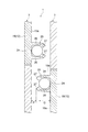
図7は、本発明の第2実施形態に係る蓄電装置パックとして電池パックを概略的に示す平面視断面図である。図7において、本実施形態の電池パック1は、上記第1実施形態と同様に、筐体2と複数の電池モジュール3とを備えている。電池モジュール3は、複数のボルト(図示せず)により筐体2の本体壁2a及び側壁2bの内壁面に固定されている。
FIG. 7 is a plan sectional view schematically showing a battery pack as a power storage device pack according to the second embodiment of the present invention. 7, the
複数の電池モジュール3は、図8に示されるように、セルホルダ12の外側面19a同士が互いに対向するように配置されている。互いに対向する2つの電池モジュール3におけるセルホルダ12の外側面19aに設けられた支持部25は、互いにセルホルダ12の高さ方向にずれている。支持部25は、上記第1実施形態と同様に、1対の係止片26を有している。
As shown in FIG. 8, the plurality of
互いに対向する2つの電池モジュール3の一方におけるセルホルダ12の外側面19aから突出した係止片26と当該2つの電池モジュール3の他方におけるセルホルダ12の外側面19aとの間隔Pは、ハーネス24の直径Qよりも短い。
The distance P between the locking
このような本実施形態においても、ハーネス24を電池モジュール3に組み付ける際には、電池モジュール3の正面側からハーネス24をセルホルダ12の外側面19aに向けて移動させて各係止片26の間に押し込むことになるため、ハーネス24を組み付けやすくなる。これにより、上記第1実施形態と同様に、ハーネス24を組み付ける際の作業性が向上する。
Also in the present embodiment, when the
また、振動衝撃等によってハーネス24が支持部25から外れようとしても、ハーネス24がセルホルダ12の外側面19aに当たり、ハーネス24が各係止片26の間から完全に抜け出ることはない。これにより、ハーネス24が支持部25から外れることが防止される。
Further, even if the
図9は、図8に示された電池パック1の変形例において支持部25を含む部分を示す拡大断面図である。本変形例では、互いに対向する2つの電池モジュール3におけるセルホルダ12の外側面19aに設けられた支持部25は、互いに対向している。
FIG. 9 is an enlarged cross-sectional view showing a portion including the
互いに対向する2つの電池モジュール3の一方におけるセルホルダ12の外側面19aから突出した係止片26と当該2つの電池モジュール3の他方におけるセルホルダ12の外側面19aから突出した係止片26との間隔Pは、ハーネス24の直径Qよりも短い。
Distance between the locking
このような本変形例においては、振動衝撃等によってハーネス24が支持部25から外れようとしても、ハーネス24が対向するもう一方の支持部25に当たり、ハーネス24が各係止片26の間から完全に抜け出ることはない。これにより、ハーネス24が支持部25から外れることが防止される。
In this modified example, even if the
なお、本発明は、上記実施形態には限定されない。例えば上記実施形態では、支持部25は、セルホルダ12の一方の外側面19aに設けられているが、特にその形態には限られず、支持部25は、セルホルダ12の両方の外側面19aに設けられていてもよい。
Note that the present invention is not limited to the above embodiment. For example, in the above-described embodiment, the
また、上記実施形態では、支持部25は、セルホルダ12の外側面19aに上下2つ設けられているが、特にその形態には限られず、支持部25は、セルホルダ12の外側面19aに1つのみ設けられていてもよいし、或いはセルホルダ12の外側面19aに3つ以上設けられていてもよい。
Further, in the above embodiment, two upper and
また、上記実施形態では、1対の係止片26の先端部に、ハーネス24が引っ掛かる爪27が設けられているが、そのような爪27は特に無くてもよい。この場合には、ハーネス24を電池モジュール3に組み付ける際に、ハーネス24を各係止片26の間にスムーズに押し込むことができる。
Further, in the above-described embodiment, the
さらに、上記実施形態では、電池ユニット4は、各二次電池11を個別に保持する複数のセルホルダ12を有しているが、使用するセルホルダとしては、特にそれには限られず、複数の二次電池11を一括して保持するタイプであってもよい。
Further, in the above embodiment, the
また、上記実施形態では、複数の二次電池11を二次電池11の配列方向に拘束する拘束ユニット10は、エンドプレート6、ボルト8及びナット(図示せず)から構成されているが、特にその形態には限られず、ボルト8及びナットに代えてゴムバンド等を使用してもよい。
In the above-described embodiment, the restraining
また、上記実施形態では、筐体2内に複数の電池モジュール3が収容されているが、筐体2内に収容される電池モジュール3の数としては、特にそれには限られない。上記第1実施形態では、筐体2内に収容される電池モジュール3の数としては、1つでもよい。上記第2実施形態では、筐体2内に収容される電池モジュール3の数としては、少なくとも2つあればよい。
Further, in the above embodiment, the plurality of
さらに、上記実施形態は、リチウムイオン二次電池等の二次電池11を有する電池モジュール3を備えた電池パック1であるが、本発明は、特に二次電池11には限られず、例えば電気二重層キャパシタまたはリチウムイオンキャパシタ等の蓄電装置を有する蓄電装置モジュールを備えた蓄電装置パックにも適用可能である。
Further, the above embodiment is the
1…電池パック(蓄電装置パック)、2…筐体、2b…側壁(壁)、3…電池モジュール(蓄電装置モジュール)、10…拘束ユニット、11…二次電池(蓄電装置)、12…セルホルダ(ホルダ)、19a…外側面、24…ハーネス、25…支持部、26…係止片、30…弾性体。
DESCRIPTION OF
Claims (4)
前記蓄電装置モジュールは、一方向に配列された複数の蓄電装置と、前記蓄電装置を保持するホルダと、前記複数の蓄電装置を前記蓄電装置の配列方向に拘束する拘束ユニットとを有し、
前記ホルダの外側面には、ハーネスを支持する支持部が設けられており、
前記支持部は、前記ホルダの外側面から側方に向けて延びるように突出し、前記ハーネスを前記ホルダの高さ方向に挟んで係止する1対の係止片を有し、
前記ホルダの外側面は、前記筐体を構成する壁と対向しており、
前記係止片と前記壁との間には、前記ハーネスの直径よりも短い間隔が設けられており、
前記1対の係止片の先端部には、前記ハーネスが引っ掛かる爪が互いに対向するように設けられており、
前記1対の係止片の各爪間の隙間は、前記壁の側に向いていることを特徴とする蓄電装置パック。 In a power storage device pack including a housing and a power storage device module housed in the housing,
The power storage device module has a plurality of power storage devices arranged in one direction, a holder that holds the power storage device, and a restraining unit that restrains the plurality of power storage devices in the arrangement direction of the power storage device,
A support portion for supporting a harness is provided on an outer surface of the holder,
The support portion protrudes to extend laterally from an outer surface of the holder, and has a pair of locking pieces that lock the harness by sandwiching the harness in a height direction of the holder,
An outer surface of the holder is opposed to a wall constituting the housing,
An interval shorter than the diameter of the harness is provided between the locking piece and the wall ,
At the tips of the pair of locking pieces, claws on which the harness is hooked are provided so as to face each other,
The gap between the claws of the pair of locking pieces is directed toward the wall .
前記蓄電装置モジュールは、一方向に配列された複数の蓄電装置と、前記蓄電装置を保持するホルダと、前記複数の蓄電装置を前記蓄電装置の配列方向に拘束する拘束ユニットとを有し、
前記ホルダの外側面には、ハーネスを支持する支持部が設けられており、
前記支持部は、前記ホルダの外側面から側方に向けて延びるように突出し、前記ハーネスを前記ホルダの高さ方向に挟んで係止する1対の係止片を有し、
前記ホルダの外側面は、前記筐体を構成する壁と対向しており、
前記壁における前記ホルダの外側面と対向する面には、弾性体が固定されており、
前記係止片と前記弾性体との間には、前記ハーネスの直径よりも短い間隔が設けられており、
前記1対の係止片の先端部には、前記ハーネスが引っ掛かる爪が互いに対向するように設けられており、
前記1対の係止片の各爪間の隙間は、前記壁の側に向いていることを特徴とする蓄電装置パック。 In a power storage device pack including a housing and a power storage device module housed in the housing,
The power storage device module has a plurality of power storage devices arranged in one direction, a holder that holds the power storage device, and a restraining unit that restrains the plurality of power storage devices in the arrangement direction of the power storage device,
A support portion for supporting a harness is provided on an outer surface of the holder,
The support portion protrudes to extend laterally from an outer surface of the holder, and has a pair of locking pieces that lock the harness by sandwiching the harness in a height direction of the holder,
An outer surface of the holder is opposed to a wall constituting the housing,
An elastic body is fixed to a surface of the wall facing the outer surface of the holder,
An interval shorter than the diameter of the harness is provided between the locking piece and the elastic body ,
At the tips of the pair of locking pieces, claws on which the harness is hooked are provided so as to face each other,
The gap between the claws of the pair of locking pieces is directed toward the wall .
前記蓄電装置モジュールは、一方向に配列された複数の蓄電装置と、前記蓄電装置を保持するホルダと、前記複数の蓄電装置を前記蓄電装置の配列方向に拘束する拘束ユニットとを有し、
前記ホルダの外側面には、ハーネスを支持する支持部が設けられており、
前記支持部は、前記ホルダの外側面から側方に向けて延びるように突出し、前記ハーネスを前記ホルダの高さ方向に挟んで係止する1対の係止片を有し、
前記筐体内には、前記蓄電装置モジュールが少なくとも2つ収容されており、
前記2つの蓄電装置モジュールは、前記ホルダの外側面同士が互いに対向するように配置されており、
前記2つの蓄電装置モジュールにおける前記ホルダの外側面に設けられた前記支持部は、互いに前記ホルダの高さ方向にずれており、
前記2つの蓄電装置モジュールの一方における前記ホルダの外側面から突出した前記係止片と前記2つの蓄電装置モジュールの他方における前記ホルダの外側面との間には、前記ハーネスの直径よりも短い間隔が設けられており、
前記1対の係止片の先端部には、前記ハーネスが引っ掛かる爪が互いに対向するように設けられており、
前記2つの蓄電モジュールの一方における前記1対の係止片の各爪間の隙間は、前記2つの蓄電モジュールの他方における前記ホルダの外側面の側に向いていることを特徴とする蓄電装置パック。 In a power storage device pack including a housing and a power storage device module housed in the housing,
The power storage device module has a plurality of power storage devices arranged in one direction, a holder that holds the power storage device, and a restraining unit that restrains the plurality of power storage devices in the arrangement direction of the power storage device,
A support portion for supporting a harness is provided on an outer surface of the holder,
The support portion protrudes to extend laterally from an outer surface of the holder, and has a pair of locking pieces that lock the harness by sandwiching the harness in a height direction of the holder,
At least two of the power storage device modules are accommodated in the housing,
The two power storage device modules are arranged such that outer surfaces of the holder face each other,
The support portions provided on the outer surface of the holder in the two power storage device modules are shifted from each other in a height direction of the holder,
An interval shorter than the diameter of the harness is between the locking piece protruding from the outer surface of the holder on one of the two power storage device modules and the outer surface of the holder on the other of the two power storage device modules. Is provided ,
At the distal ends of the pair of locking pieces, claws on which the harness is hooked are provided so as to face each other,
A power storage device pack , wherein a gap between the claws of the pair of locking pieces in one of the two power storage modules faces an outer surface of the holder in the other of the two power storage modules. .
前記蓄電装置モジュールは、一方向に配列された複数の蓄電装置と、前記蓄電装置を保持するホルダと、前記複数の蓄電装置を前記蓄電装置の配列方向に拘束する拘束ユニットとを有し、
前記ホルダの外側面には、ハーネスを支持する支持部が設けられており、
前記支持部は、前記ホルダの外側面から側方に向けて延びるように突出し、前記ハーネスを前記ホルダの高さ方向に挟んで係止する1対の係止片を有し、
前記筐体内には、前記蓄電装置モジュールが少なくとも2つ収容されており、
前記2つの蓄電装置モジュールは、前記ホルダの外側面同士が互いに対向するように配置されており、
前記2つの蓄電装置モジュールにおける前記ホルダの外側面に設けられた前記支持部は、互いに対向しており、
前記2つの蓄電装置モジュールの一方における前記ホルダの外側面から突出した前記係止片と前記2つの蓄電装置モジュールの他方における前記ホルダの外側面から突出した前記係止片との間には、前記ハーネスの直径よりも短い間隔が設けられており、
前記1対の係止片の先端部には、前記ハーネスが引っ掛かる爪が互いに対向するように設けられており、
前記2つの蓄電モジュールの一方における前記1対の係止片の各爪間の隙間は、前記2つの蓄電モジュールの他方における前記ホルダの外側面の側に向いていることを特徴とする蓄電装置パック。 In a power storage device pack including a housing and a power storage device module housed in the housing,
The power storage device module has a plurality of power storage devices arranged in one direction, a holder that holds the power storage device, and a restraining unit that restrains the plurality of power storage devices in the arrangement direction of the power storage device,
A support portion for supporting a harness is provided on an outer surface of the holder,
The support portion protrudes to extend laterally from an outer surface of the holder, and has a pair of locking pieces that lock the harness by sandwiching the harness in a height direction of the holder,
At least two of the power storage device modules are accommodated in the housing,
The two power storage device modules are arranged such that outer surfaces of the holder face each other,
The support portions provided on the outer surface of the holder in the two power storage device modules are opposed to each other,
Between the locking piece protruding from the outer surface of the holder in one of the two power storage device modules and the locking piece protruding from the outer surface of the holder in the other of the two power storage device modules, An interval shorter than the diameter of the harness is provided ,
At the distal ends of the pair of locking pieces, claws on which the harness is hooked are provided so as to face each other,
A power storage device pack , wherein a gap between the claws of the pair of locking pieces in one of the two power storage modules faces an outer surface of the holder in the other of the two power storage modules. .
Priority Applications (2)
| Application Number | Priority Date | Filing Date | Title |
|---|---|---|---|
| JP2016078312A JP6658233B2 (en) | 2016-04-08 | 2016-04-08 | Power storage device pack |
| PCT/JP2017/012893 WO2017175636A1 (en) | 2016-04-08 | 2017-03-29 | Accumulator device pack |
Applications Claiming Priority (1)
| Application Number | Priority Date | Filing Date | Title |
|---|---|---|---|
| JP2016078312A JP6658233B2 (en) | 2016-04-08 | 2016-04-08 | Power storage device pack |
Publications (3)
| Publication Number | Publication Date |
|---|---|
| JP2017188396A JP2017188396A (en) | 2017-10-12 |
| JP2017188396A5 JP2017188396A5 (en) | 2018-12-13 |
| JP6658233B2 true JP6658233B2 (en) | 2020-03-04 |
Family
ID=60001140
Family Applications (1)
| Application Number | Title | Priority Date | Filing Date |
|---|---|---|---|
| JP2016078312A Active JP6658233B2 (en) | 2016-04-08 | 2016-04-08 | Power storage device pack |
Country Status (2)
| Country | Link |
|---|---|
| JP (1) | JP6658233B2 (en) |
| WO (1) | WO2017175636A1 (en) |
Families Citing this family (1)
| Publication number | Priority date | Publication date | Assignee | Title |
|---|---|---|---|---|
| WO2023188221A1 (en) * | 2022-03-30 | 2023-10-05 | ビークルエナジージャパン株式会社 | Battery pack |
Family Cites Families (6)
| Publication number | Priority date | Publication date | Assignee | Title |
|---|---|---|---|---|
| US9028996B2 (en) * | 2011-09-29 | 2015-05-12 | Lithium Energy Japan | Battery pack |
| JP6011281B2 (en) * | 2012-11-29 | 2016-10-19 | 株式会社豊田自動織機 | Battery pack |
| JP6044405B2 (en) * | 2013-03-21 | 2016-12-14 | 株式会社豊田自動織機 | Battery pack and battery module assembly method |
| JP6053643B2 (en) * | 2013-08-29 | 2016-12-27 | 古河電気工業株式会社 | In-battery wiring module of battery pack |
| JP6318862B2 (en) * | 2014-05-29 | 2018-05-09 | 株式会社豊田自動織機 | Battery module and battery pack |
| JP6409345B2 (en) * | 2014-06-04 | 2018-10-24 | 株式会社豊田自動織機 | Battery module and battery pack |
-
2016
- 2016-04-08 JP JP2016078312A patent/JP6658233B2/en active Active
-
2017
- 2017-03-29 WO PCT/JP2017/012893 patent/WO2017175636A1/en active Application Filing
Also Published As
| Publication number | Publication date |
|---|---|
| JP2017188396A (en) | 2017-10-12 |
| WO2017175636A1 (en) | 2017-10-12 |
Similar Documents
| Publication | Publication Date | Title |
|---|---|---|
| JP6642696B2 (en) | Power supply | |
| US20140212722A1 (en) | Battery module assembly of improved reliability and battery pack employed with the same | |
| CN111149236B (en) | Battery pack | |
| EP2731166A1 (en) | Rack for an energy storage system | |
| US10367180B2 (en) | Battery pack | |
| CN107482143B (en) | Battery pack | |
| WO2015156053A1 (en) | Battery pack | |
| KR101750487B1 (en) | Battery Module Having Mounting Means of Bus Bar and External Input-Output Terminal | |
| JP4806924B2 (en) | Assembled battery | |
| JP6609989B2 (en) | Battery module | |
| JP2019220437A (en) | Battery module | |
| EP2490277B1 (en) | Battery Module | |
| JP6658233B2 (en) | Power storage device pack | |
| KR102082497B1 (en) | Fuse assembly structure of secondary battery pack | |
| JP6449107B2 (en) | Power storage device | |
| JP5555113B2 (en) | Battery pack and electric tool provided with the battery pack | |
| JP6358047B2 (en) | Battery module and battery pack | |
| JP6520156B2 (en) | Power storage device and power storage device module | |
| WO2016021242A1 (en) | Battery module | |
| JP6780374B2 (en) | Battery module | |
| JP2019145241A (en) | Battery pack | |
| WO2014049653A1 (en) | Battery block | |
| JP2018005996A (en) | Battery module | |
| KR102187275B1 (en) | Battery module fixing pallet | |
| JP6933542B2 (en) | Battery pack |
Legal Events
| Date | Code | Title | Description |
|---|---|---|---|
| A521 | Request for written amendment filed |
Free format text: JAPANESE INTERMEDIATE CODE: A523 Effective date: 20181030 |
|
| A621 | Written request for application examination |
Free format text: JAPANESE INTERMEDIATE CODE: A621 Effective date: 20181030 |
|
| A131 | Notification of reasons for refusal |
Free format text: JAPANESE INTERMEDIATE CODE: A131 Effective date: 20190618 |
|
| A521 | Request for written amendment filed |
Free format text: JAPANESE INTERMEDIATE CODE: A523 Effective date: 20190814 |
|
| TRDD | Decision of grant or rejection written | ||
| A01 | Written decision to grant a patent or to grant a registration (utility model) |
Free format text: JAPANESE INTERMEDIATE CODE: A01 Effective date: 20200107 |
|
| A61 | First payment of annual fees (during grant procedure) |
Free format text: JAPANESE INTERMEDIATE CODE: A61 Effective date: 20200120 |
|
| R151 | Written notification of patent or utility model registration |
Ref document number: 6658233 Country of ref document: JP Free format text: JAPANESE INTERMEDIATE CODE: R151 |