EP2731166A1 - Rack for an energy storage system - Google Patents
Rack for an energy storage system Download PDFInfo
- Publication number
- EP2731166A1 EP2731166A1 EP20130172290 EP13172290A EP2731166A1 EP 2731166 A1 EP2731166 A1 EP 2731166A1 EP 20130172290 EP20130172290 EP 20130172290 EP 13172290 A EP13172290 A EP 13172290A EP 2731166 A1 EP2731166 A1 EP 2731166A1
- Authority
- EP
- European Patent Office
- Prior art keywords
- rack
- tray
- region
- fixing unit
- unit
- Prior art date
- Legal status (The legal status is an assumption and is not a legal conclusion. Google has not performed a legal analysis and makes no representation as to the accuracy of the status listed.)
- Granted
Links
Images


Classifications
-
- H—ELECTRICITY
- H01—ELECTRIC ELEMENTS
- H01M—PROCESSES OR MEANS, e.g. BATTERIES, FOR THE DIRECT CONVERSION OF CHEMICAL ENERGY INTO ELECTRICAL ENERGY
- H01M50/00—Constructional details or processes of manufacture of the non-active parts of electrochemical cells other than fuel cells, e.g. hybrid cells
- H01M50/20—Mountings; Secondary casings or frames; Racks, modules or packs; Suspension devices; Shock absorbers; Transport or carrying devices; Holders
- H01M50/218—Mountings; Secondary casings or frames; Racks, modules or packs; Suspension devices; Shock absorbers; Transport or carrying devices; Holders characterised by the material
- H01M50/22—Mountings; Secondary casings or frames; Racks, modules or packs; Suspension devices; Shock absorbers; Transport or carrying devices; Holders characterised by the material of the casings or racks
- H01M50/227—Organic material
-
- H—ELECTRICITY
- H01—ELECTRIC ELEMENTS
- H01M—PROCESSES OR MEANS, e.g. BATTERIES, FOR THE DIRECT CONVERSION OF CHEMICAL ENERGY INTO ELECTRICAL ENERGY
- H01M50/00—Constructional details or processes of manufacture of the non-active parts of electrochemical cells other than fuel cells, e.g. hybrid cells
- H01M50/20—Mountings; Secondary casings or frames; Racks, modules or packs; Suspension devices; Shock absorbers; Transport or carrying devices; Holders
- H01M50/204—Racks, modules or packs for multiple batteries or multiple cells
- H01M50/207—Racks, modules or packs for multiple batteries or multiple cells characterised by their shape
- H01M50/213—Racks, modules or packs for multiple batteries or multiple cells characterised by their shape adapted for cells having curved cross-section, e.g. round or elliptic
-
- H—ELECTRICITY
- H01—ELECTRIC ELEMENTS
- H01M—PROCESSES OR MEANS, e.g. BATTERIES, FOR THE DIRECT CONVERSION OF CHEMICAL ENERGY INTO ELECTRICAL ENERGY
- H01M50/00—Constructional details or processes of manufacture of the non-active parts of electrochemical cells other than fuel cells, e.g. hybrid cells
- H01M50/20—Mountings; Secondary casings or frames; Racks, modules or packs; Suspension devices; Shock absorbers; Transport or carrying devices; Holders
- H01M50/256—Carrying devices, e.g. belts
-
- H—ELECTRICITY
- H01—ELECTRIC ELEMENTS
- H01M—PROCESSES OR MEANS, e.g. BATTERIES, FOR THE DIRECT CONVERSION OF CHEMICAL ENERGY INTO ELECTRICAL ENERGY
- H01M50/00—Constructional details or processes of manufacture of the non-active parts of electrochemical cells other than fuel cells, e.g. hybrid cells
- H01M50/20—Mountings; Secondary casings or frames; Racks, modules or packs; Suspension devices; Shock absorbers; Transport or carrying devices; Holders
- H01M50/262—Mountings; Secondary casings or frames; Racks, modules or packs; Suspension devices; Shock absorbers; Transport or carrying devices; Holders with fastening means, e.g. locks
- H01M50/264—Mountings; Secondary casings or frames; Racks, modules or packs; Suspension devices; Shock absorbers; Transport or carrying devices; Holders with fastening means, e.g. locks for cells or batteries, e.g. straps, tie rods or peripheral frames
-
- Y—GENERAL TAGGING OF NEW TECHNOLOGICAL DEVELOPMENTS; GENERAL TAGGING OF CROSS-SECTIONAL TECHNOLOGIES SPANNING OVER SEVERAL SECTIONS OF THE IPC; TECHNICAL SUBJECTS COVERED BY FORMER USPC CROSS-REFERENCE ART COLLECTIONS [XRACs] AND DIGESTS
- Y02—TECHNOLOGIES OR APPLICATIONS FOR MITIGATION OR ADAPTATION AGAINST CLIMATE CHANGE
- Y02E—REDUCTION OF GREENHOUSE GAS [GHG] EMISSIONS, RELATED TO ENERGY GENERATION, TRANSMISSION OR DISTRIBUTION
- Y02E60/00—Enabling technologies; Technologies with a potential or indirect contribution to GHG emissions mitigation
- Y02E60/10—Energy storage using batteries
Definitions
- Embodiments relate to an energy storage system, which can suppress trays from vibrating in a rack.
- An energy storage system can be associated with a new renewal energy and power system, such as a solar cell, and is configured to store power when the power demanded from a load is small and then use the stored power when the demand for power is increased.
- a new renewal energy and power system such as a solar cell
- An example of the energy storage system includes a large quantity of secondary batteries of the type used in electronic devices, such as cellular phones, or notebook computers.
- the large quantity of secondary batteries may be accommodated in multiple trays, which are accommodated in a rack.
- the rack accommodating the trays needs to be designed to secure stability against a vibration, such as earthquake or external shock.
- an energy storage system comprising a rack including side frames; a guide plate formed between the side frames; at least one tray fixing unit inwardly protruding from the guide plate; a tray supporting unit inserted into a portion between the side frames along the guide plate and having one end positioned between the guide plate and the tray fixing unit.
- a distance between the tray fixing unit and the tray supporting unit may be 0.5 mm or less.
- the tray fixing unit may include a first region coupled to the guide plate by an external coupling member at its one end.
- the tray fixing unit may include a second region welded and coupled to the guide plate at the other end symmetrical to the one end.
- the tray fixing unit may include a third region protruding between the first region and the second region and fixing the tray supporting unit from the top.
- the third region may fix sides of the tray supporting unit from the top.
- the energy storage system according to the present invention includes at least one tray fixing unit inwardly protruding with respect to the guide plate formed between the side frames, the tray supporting unit inserted into the inside of the side frames along the guide plate is vertically fixed, thereby easily preventing the tray supporting unit and the trays from vibrating in the rack.
- a rack for an energy storage system the rack being for accommodating at least one tray, each tray comprising at least one battery; wherein the rack comprises at least one shelf unit, each shelf unit being arranged to receive a said tray, each shelf unit comprising at least one tray fixing unit arranged to constrain movement of the said tray in a direction away from the shelf unit.
- Preferred features of this aspect are set out in claims 2 to 15.
- an energy storage system as set out in claim 16.
- FIG. 1 is a perspective view of an energy storage system according to an embodiment of the present invention
- FIG. 2 is an exploded perspective view of a tray of the energy storage system according to an embodiment of the present invention
- FIG. 3 is a perspective view of a tray supporting unit of the energy storage system according to an embodiment of the present invention
- FIG. 4 is a perspective view of a rack of the energy storage system according to an embodiment of the present invention
- FIG. 5 is an enlarged view of a portion where the tray fixing unit is formed in the rack of the energy storage system according to an embodiment of the present invention
- FIG. 6 illustrates a state in which the tray supporting unit is combined with the tray fixing unit shown in FIG. 5
- FIG. 7 is a cross-sectional view taken along the line A-A' of FIG.
- FIG. 8 is a perspective view of a tray fixing unit of the energy storage system according to an embodiment of the present invention
- FIG. 9 is a rear view illustrating a state in which trays formed in the rack are connected in the energy storage system according to an embodiment of the present invention.
- the energy storage system 100 includes trays 110, a tray supporting unit 120, a rack 130, connector units 150, a battery management box 160, a switch box 170, power supply wires 180 and communication wires 190
- the energy storage system 100 may further include covers 140 coupled to front and side surfaces of the rack 130.
- the trays 110 are accommodated in the rack 130 and include a first case 111 and a second case 112.
- the first case 111 may be shaped of a box having an accommodation space inside and may include a plurality of partitions 113 in the internal space to separately accommodate a plurality of battery cells 114.
- the second case 112 may be shaped of a plate and may be coupled to the first case 111 ccommodating the plurality of battery cells 114.
- the first case 111 nd the second case 112 may be made of an insulating material, such as a plastic material.
- the number of the trays 110 may be adjusted according to the size of the rack 130.
- each of the trays 110 may further include a battery management system (BMS) embedded therein to control charging and discharging of the battery cells 114.
- BMS battery management system
- a plurality of tray supporting units 120 are inserted into the rack 130 to be coupled thereto.
- Each tray supporting unit 120 supports bottom portions of a tray 110, so that the trays 110 can be safely mounted in the rack 130.
- Positions of the tray supporting units 120 are fixed within the rack 130, thereby allowing the trays no positioned thereon to be safety placed in the rack 130.
- each tray supporting unit 120 includes a first plate 121 formed in one direction to be inserted into the rack 130 and a second plate 122 formed to be perpendicular to the first plate 121.
- the first plate 121 is inserted into the rack 130, and a position of its side portion 121a is fixed within the rack 130, thereby preventing the trays 110 from vibrating in the rack 130 even with an external vibration applied to the rack 130.
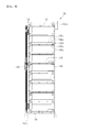
- the rack 130 includes a top frame 131, a pair of side frames 132 downwardly extending from the top frame 131 to be perpendicular to the top frame 131, a middle frame 133 installed between the side frames 132 to be parallel to the side frames 132, and a bottom frame 134 formed at a bottom portion of the rack 130 to be connected to the side frames 132 and the middle frame 133.
- the rack 130 includes a plurality of first rack frames 135 installed on a front surface between the top frame 131 and the bottom frame 134 to be parallel to the top frame 131 and the bottom frame 134, and a plurality of second rack frames 136 installed on a rear surface between the top frame 131 and the bottom frame 134.
- the guide plate 137 is further formed widthwise in each of the side frames 132 and the middle frame 133 to connect the first rack frames 135 and the second rack frames 136.
- the guide plate 137 is formed to have a length corresponding to a distance between each of the first rack frames 135 and each of the second rack frames 136, that is to say, a thickness of the rack 130.
- the guide plate 137 may include a first region 137a extending from the first rack frame 135 to the second rack frame 136 on top surfaces of the first rack frame 135 and the second rack frame 136, and a second region 137b vertically bent from the first region 137a.
- the first region 137a supports the tray supporting unit 120 from the bottom and is fastened to the tray supporting unit 120.
- the tray supporting unit 120 may move along the first region 137a to be inserted into the rack 130.
- the second region 137b is a region to which the following components for fixing the tray supporting unit 120 are coupled.
- the rack 130 includes a tray fixing unit 138 formed inward of the second region 137b of the guide plate 137.
- the tray fixing unit 138 protrudes on a top portion of the tray supporting unit 120 and supports the top portion of the tray supporting unit 120. Therefore, the tray fixing unit 138 controls vertical vibration of the tray supporting unit 120, thereby controlling vibration of the trays 110.
- each tray fixing unit 138 is arranged to constrain movement of a tray 110 in a direction away from the tray supporting unit 120.
- each tray fixing unit 138 and corresponding tray supporting unit 120 forms a shelf unit of the rack 130.
- the tray fixing unit 138 of this embodiment includes a first region 138a coupled to the second region 137b of the guide plate 137 at its one end.
- the first region 138a includes at least one hole 138b formed therein to be coupled to the guide plate 137 by external coupling means (e.g., bolts, 10).
- each first region 138a may be coupled to the corresponding guide plate 137 by other means.
- the tray fixing unit i38 includes a second region i38c coupled to the second region 137b of the guide plate 137 at the other end symmetrical to the first region 138a.
- the second region 138c may be maintained at a state in which it is coupled to the guide plate 137 by, for example, welding.
- each second region 138c may be coupled to the corresponding guide plate 137 by other means.
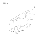
- the tray fixing unit 138 includes a pair of third regions 138d protruding from the first region 138a and the second region 138c, respectively, and a fourth region 138e formed between the third regions 138d. Since the fourth region 138e protrudes on the top portion of the tray supporting unit 120, vertical vibration of the tray supporting unit 120 can be suppressed. Therefore, it is possible to prevent the tray supporting unit 120 and the trays 110 from vibrating, thereby increasing stability of the energy storage system 100.
- a length t1 of the tray fixing unit 138 may be 110 mm or greater. If the length ti of the tray fixing unit 138 is 110 mm or greater, the tray fixing unit 138 is coupled to the second region 137b of the guide plate 137, and provides for a length long enough to fix the tray supporting unit 120.
- a width t2 of the tray fixing unit 138 may be 30 mm or greater. If the width t2 of the tray fixing unit 138 is 30 mm or greater, a sufficient coupling strength between each of the first region 138a and the second region 138c of the tray fixing unit 138 and the guide plate 137 can be secured.
- a height t3 of the third regions 138d protruding from the tray fixing unit 138 may be 10 mm or greater. If the height t3 of the third regions 138d protruding from the tray fixing unit 138 is 10 mm or greater, the tray fixing unit 138 can prevent edges of the side portion 121a of the tray supporting unit 120 from deforming while stably supporting the tray supporting unit 120.
- a length t4 of the fourth region 138e of the tray fixing unit 138 may be 60 mm or greater. If the length t4 of the fourth region i38e of the tray fixing unit 138 is 60 mm or greater, the fourth region 138e can prevent edges of the side portion 121a of the tray supporting unit 120 from deforming while stably supporting the tray supporting unit 120.
- a distance h1 between the tray fixing unit 138 and the tray supporting unit 120 may be 0.5 mm or less. If the distance hi between the tray fixing unit 138 and the tray supporting unit 120 is 0.5 mm or less, the tray supporting unit 120 vertically tightly contacts with the tray fixing unit 138 to be prevented from vertically vibrating, and the side portion 121a of the tray supporting unit 120 can be prevented from deforming due to external vibration.
- the pair of third regions 138d are formed by bending the tray fixing unit 138. It will, however, be appreciated that the shape of the tray fixing unit 138 described above could be manufactured in a variety of different ways and could take a variety of different forms.
- the cover 140 may include a front cover 141 formed on a front surface of the rack 130 and a side cover 142 formed on the side surface of the rack 130.
- the front cover 141 has hinges formed at both edges to be opened by a user when necessary.
- the side cover 142 is coupled to side frames 132 of the rack 130 to protect the trays 110 provided inside.
- the connector units 150 are formed on a rear surface of the rack 130 opposite to the front cover 141.
- the number of the connector units 150 is equal to that of the trays 110, and the connector units 150 are coupled to the trays 110, respectively, to be electrically connected to the battery cells 114) provided in the trays 110.
- the connector units 150 provide to the battery cells 114 with paths for charging and discharging operations and communication.
- the battery management box 160 has the same size as the tray 110 to be accommodated in the rack 130.
- the battery management box 160 includes circuit devices for controlling communications with the respective trays 110.
- the battery management box 170 can identify states of the battery cells 114 accommodated in the trays 110 through the circuit devices.
- the switch box 170 has the same size as the tray no to be accommodated in the rack 130.
- the switch box 170 includes a protection circuit device for protecting the battery cells 114.
- the protection circuit device may be a fuse or switching device that disconnects the flow of current when the current supplied to the battery cells 114 is greater than a current limit of the battery cells 114.
- the power supply wires 180 connect the connector units 150 and the switch box 170.
- the power supply wires 180 establish electrical connections between the trays 110 coupled to the connector units 150 while providing charging and discharging paths.
- the communication wires 190 connect the connector units 150, the battery management box 160, and the switch box 170 to one another.
- the communication wires 190 provide communication paths to allow the battery management box 160 to monitor states of the battery cells 114 provided in the trays 110.
- FIG. 10 is an enlarged view of a portion where a tray fixing unit is formed in a rack of an energy storage system according to another embodiment of the present invention
- FIG. 11 is a cross-sectional view of a portion where the tray fixing unit is formed in the rack of the energy storage system according to another embodiment of the present invention
- FIG. 12 is an enlarged view of the tray fixing unit in the energy storage system according to another embodiment of the present invention.
- the energy storage system includes a rack 230 coupled to tray supporting units 120.
- the rack 230 includes tray fixing units 238 coupled to guide plates 137.
- Each of the tray fixing units 238 includes a first region 238a coupled to a second region 137b of each of the guide plates 137 at its one end, and the first region 238a includes at least one hole 238b.
- the tray fixing units 238 are coupled to the guide plates 137 through external coupling means.
- each first region 238c may be coupled to the corresponding guide plate 137 by other means.
- each tray fixing unit 238 and corresponding tray supporting unit 120 forms a shelf unit of the rack 230.
- the tray fixing unit 238 includes a second region 238c coupled to the guide plate 137 at the other end symmetrical to the first region 238a.
- the second region 238c may be coupled to the guide plate 137 by, for example, welding.
- each second region 238c may be coupled to the corresponding guide plate 137 by other means.
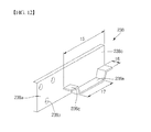
- the tray fixing unit 238 includes a pair of third regions 238d protruding the first region 238a and the second region 238c, respectively, and a fourth region 238e between the third regions 238d to be tilted with respect to the third regions 238d.
- the fourth region 238e extends in a lengthwise direction of the tray fixing unit 238 and fixes a side portion 121a of the tray supporting unit 120, thereby fixing the tray supporting unit 120 and trays.
- a length t5 of each of the third region 238d and the fourth region 238e may be 60 mm or greater. If the length t5 of each of the third region 238d and the fourth region 238e is 60 mm or greater, the fourth region 238e can prevent edges of the side portion 121a of the tray supporting unit 120 from deforming while stably supporting the tray supporting unit 120.
- a height t6 of each of the third regions 238d and the fourth region 238e protruding from the tray fixing unit 238 may be 10 mm or greater. If the height t6 of each of the third regions 238d and the fourth region 238e protruding from the tray fixing unit 238 is 10 mm or greater, the tray fixing unit 238 can prevent edges of the side portion 121a of the tray supporting unit 120 from deforming while stably supporting the tray supporting unit 120.
- a length t7 of the fourth region 238e of the tray fixing unit 238 may be 50 mm or greater. Therefore, the fourth region 238e makes contact with the tray supporting unit 120 sufficiently longer than is necessary, thereby stably supporting the side portion 121a of the tray supporting unit 120.
- the tray fixing unit 238 comprises a plate formed between the first and second ends, and the pair of third regions 238d and the fourth region 238e are formed by flange protruding from the plate.
- a pair of fifth regions respectively protrude from each of the pair of third regions 238d in a direction towards the tray, with the fourth region 138e, 238e arranged between the pair of fifth regions 238d.
- embodiments of the invention provide a rack for an energy storage system, the rack being for accommodating at least one tray, each tray comprising at least one battery.
- the rack comprises at least one shelf unit, each shelf unit being arranged to receive a said tray, each shelf unit comprising at least one tray fixing unit arranged to constrain movement of the said tray in a direction away from the shelf unit.
- each shelf unit comprises a tray supporting unit capable of being inserted and removed from the rack.
- tray supporting units comprising a first plate for supporting a tray, with the tray fixing unit being arranged to constrain movement of the tray in a direction away from the first plate.
- each tray supporting unit may be arranged in other ways.
- each tray supporting unit may be integral with the tray.
- the bottom surface of the tray could comprise the first plate, with the tray fixing unit being arranged to constrain movement of the tray in a direction away from the first plate.
- each shelf unit could comprise a plate integral with the rack that supports each tray.
- each shelf unit could comprise a plate for supporting a tray, with the tray fixing unit arranged to prevent movement of the tray away from the plate.
- the rack can take various forms. As shown in FIGs. 1-12, the rack 130, 230 can includes a first side frame 133 and a second side frame 133, with each shelf unit comprises a guide plate 137 formed between the first side frame 133 and the second side frame 133. In such arrangements, the rack 130, 230 can further comprise a third side frame 133 and a fourth side frame 133, wherein the first side frame 133 and the second side frame 133 are located on an opposite side of the rack to the third side frame 133 and the fourth side frame 133. In such arrangements, the tray fixing units 138, 238 can inwardly protrude from a first portion 137b of guide plate 137.
- the tray supporting unit 120 can be arranged to be inserted into a portion between the side frames 133 along the guide plate 137 and having one end positioned between the guide plate 137 and the tray fixing unit 138, 238.
- the guide plate 137 can comprises a second portion 137a that is arranged to support the corresponding tray supporting unit 120.
- each shelf unit can comprise a first rack frame 135 connecting the first side frame 133 and the third side frame 133, and a second rack frame 136 connecting the second side frame 133 and the fourth side frame 133.
- the first rack frame 135 and the second rack frame 136 are arranged to support the corresponding tray supporting unit 120.
- the rack can have other forms.
- the rack can includes a side frame 133, with the tray fixing units inwardly protruding from a portion of the side frame 133.
- the rack could have a single side frame comprising a plate shape, with the tray fixing units inwardly protruding therefrom. It will be appreciated that the rack may take a number of shapes.
- the tray fixing unit 138, 238 includes a first region 138a, 238a coupled to the first portion 137b of the guide plate 137, with the first region 138a, 238a being adjacent a first end of the tray fixing unit 138, 238.
- a second region 138C, 238c of the tray fixing unit 138, 238 is coupled to the guide plate 137, with the second region 138c, 238c being adjacent a second end of the tray fixing unit 138, 238.
- a pair of third regions 138d, 238d are provided that respectively protrude from the first region 138a, 238c and the second region 138c, 238c in an inward direction.
- a fourth region 138e, 238e is provided that is arranged between the pair of third regions 138d, 238d, with the fourth region 138e, 238e arranged to constrain movement of the corresponding tray 110 in a direction away from the first plate 121.
- the pair of third regions 138d are formed by bending the tray fixing unit 138.
- the tray fixing unit 238 comprises a plate formed between the first and second ends, and the pair of third regions 238d and the fourth region 238e are formed by flange protruding from the plate.
- a pair of fifth regions respectively protrudes from each of the pair of third regions 238d in a direction towards the tray, with the fourth region 138e, 238e arranged between the pair of fifth regions 238d.
- Embodiments of the invention also provide an energy storage system 100 comprising a rack according to any one of the above mentioned embodiments, and at least one tray 110 accommodated in the rack, each tray 110 comprising at least one battery.
Abstract
Description
- Embodiments relate to an energy storage system, which can suppress trays from vibrating in a rack.
- An energy storage system can be associated with a new renewal energy and power system, such as a solar cell, and is configured to store power when the power demanded from a load is small and then use the stored power when the demand for power is increased. An example of the energy storage system includes a large quantity of secondary batteries of the type used in electronic devices, such as cellular phones, or notebook computers.
- The large quantity of secondary batteries may be accommodated in multiple trays, which are accommodated in a rack. The rack accommodating the trays needs to be designed to secure stability against a vibration, such as earthquake or external shock.
- It is a feature of an embodiment to provide an energy storage system, which can suppress trays from vibrating in a rack.
- In accordance with an embodiment of the present invention, there is provided an energy storage system comprising a rack including side frames; a guide plate formed between the side frames; at least one tray fixing unit inwardly protruding from the guide plate; a tray supporting unit inserted into a portion between the side frames along the guide plate and having one end positioned between the guide plate and the tray fixing unit.
- Here, a distance between the tray fixing unit and the tray supporting unit may be 0.5 mm or less.
- In addition, the tray fixing unit may include a first region coupled to the guide plate by an external coupling member at its one end.
- The tray fixing unit may include a second region welded and coupled to the guide plate at the other end symmetrical to the one end.
- In addition, the tray fixing unit may include a third region protruding between the first region and the second region and fixing the tray supporting unit from the top.
- Further, the third region may fix sides of the tray supporting unit from the top.
- As described above, since the energy storage system according to the present invention includes at least one tray fixing unit inwardly protruding with respect to the guide plate formed between the side frames, the tray supporting unit inserted into the inside of the side frames along the guide plate is vertically fixed, thereby easily preventing the tray supporting unit and the trays from vibrating in the rack.
- According to an aspect of the invention, there is provided a rack for an energy storage system, the rack being for accommodating at least one tray, each tray comprising at least one battery; wherein the rack comprises at least one shelf unit, each shelf unit being arranged to receive a said tray, each shelf unit comprising at least one tray fixing unit arranged to constrain movement of the said tray in a direction away from the shelf unit. Preferred features of this aspect are set out in claims 2 to 15.
- According to another aspect of the invention, there is provided an energy storage system as set out in claim 16.
-
FIG. 1 is a perspective view of an energy storage system according to an embodiment of the present invention; -
FIG. 2 is an exploded perspective view of a tray of the energy storage system according to an embodiment of the present invention; -
FIG. 3 is a perspective view of a tray supporting unit of the energy storage system according to an embodiment of the present invention; -
FIG. 4 is a perspective view of a rack of the energy storage system according to an embodiment of the present invention; -
FIG. 5 is an enlarged view of a portion where the tray fixing unit is formed in the rack of the energy storage system according to an embodiment of the present invention; -
FIG. 6 illustrates a state in which the tray supporting unit is combined with the tray fixing unit shown inFIG. 5 ; -
FIG. 7 is a cross-sectional view taken along the line A-A' ofFIG. 4 ; -
FIG. 8 is a perspective view of a tray fixing unit of the energy storage system according to an embodiment of the present invention; -
FIG. 9 is a rear view illustrating a state in which trays formed in the rack are connected in the energy storage system according to an embodiment of the present invention; -
FIG. 10 is an enlarged view of a portion where a tray fixing unit is formed in a rack of an energy storage system according to another embodiment of the present invention; -
FIG. 11 is a cross-sectional view of a portion where the tray fixing unit is formed in the rack of the energy storage system according to another embodiment of the present invention; and -
FIG. 12 is an enlarged view of the tray fixing unit in the energy storage system according to another embodiment of the present invention. - Example embodiments of the present invention will now be described in more detail with reference to accompanying drawings, such that those skilled in the art can easily practice the present invention.
-
FIG. 1 is a perspective view of an energy storage system according to an embodiment of the present invention,FIG. 2 is an exploded perspective view of a tray of the energy storage system according to an embodiment of the present invention,FIG. 3 is a perspective view of a tray supporting unit of the energy storage system according to an embodiment of the present invention,FIG. 4 is a perspective view of a rack of the energy storage system according to an embodiment of the present invention,FIG. 5 is an enlarged view of a portion where the tray fixing unit is formed in the rack of the energy storage system according to an embodiment of the present invention,FIG. 6 illustrates a state in which the tray supporting unit is combined with the tray fixing unit shown inFIG. 5 ,FIG. 7 is a cross-sectional view taken along the line A-A' ofFIG. 4 ,FIG. 8 is a perspective view of a tray fixing unit of the energy storage system according to an embodiment of the present invention, andFIG. 9 is a rear view illustrating a state in which trays formed in the rack are connected in the energy storage system according to an embodiment of the present invention. - The
energy storage system 100 includestrays 110, atray supporting unit 120, arack 130,connector units 150, abattery management box 160, aswitch box 170,power supply wires 180 andcommunication wires 190 In addition, theenergy storage system 100 may further includecovers 140 coupled to front and side surfaces of therack 130. - The
trays 110 are accommodated in therack 130 and include afirst case 111 and asecond case 112. Thefirst case 111 may be shaped of a box having an accommodation space inside and may include a plurality ofpartitions 113 in the internal space to separately accommodate a plurality ofbattery cells 114. Thesecond case 112 may be shaped of a plate and may be coupled to thefirst case 111 ccommodating the plurality ofbattery cells 114. Here, thefirst case 111 nd thesecond case 112 may be made of an insulating material, such as a plastic material. The number of thetrays 110 may be adjusted according to the size of therack 130. Meanwhile, although not shown, each of thetrays 110 may further include a battery management system (BMS) embedded therein to control charging and discharging of thebattery cells 114. - In this embodiment, a plurality of
tray supporting units 120 are inserted into therack 130 to be coupled thereto. Eachtray supporting unit 120 supports bottom portions of atray 110, so that thetrays 110 can be safely mounted in therack 130. Positions of thetray supporting units 120 are fixed within therack 130, thereby allowing the trays no positioned thereon to be safety placed in therack 130. - In this embodiment, each
tray supporting unit 120 includes afirst plate 121 formed in one direction to be inserted into therack 130 and asecond plate 122 formed to be perpendicular to thefirst plate 121. Thefirst plate 121 is inserted into therack 130, and a position of itsside portion 121a is fixed within therack 130, thereby preventing thetrays 110 from vibrating in therack 130 even with an external vibration applied to therack 130. - In this embodiment, the
rack 130 includes atop frame 131, a pair ofside frames 132 downwardly extending from thetop frame 131 to be perpendicular to thetop frame 131, amiddle frame 133 installed between theside frames 132 to be parallel to theside frames 132, and abottom frame 134 formed at a bottom portion of therack 130 to be connected to theside frames 132 and themiddle frame 133. In addition, therack 130 includes a plurality offirst rack frames 135 installed on a front surface between thetop frame 131 and thebottom frame 134 to be parallel to thetop frame 131 and thebottom frame 134, and a plurality ofsecond rack frames 136 installed on a rear surface between thetop frame 131 and thebottom frame 134. - In addition, the
guide plate 137 is further formed widthwise in each of theside frames 132 and themiddle frame 133 to connect thefirst rack frames 135 and thesecond rack frames 136. Theguide plate 137 is formed to have a length corresponding to a distance between each of thefirst rack frames 135 and each of thesecond rack frames 136, that is to say, a thickness of therack 130. - The
guide plate 137 may include afirst region 137a extending from thefirst rack frame 135 to thesecond rack frame 136 on top surfaces of thefirst rack frame 135 and thesecond rack frame 136, and asecond region 137b vertically bent from thefirst region 137a. Thefirst region 137a supports thetray supporting unit 120 from the bottom and is fastened to thetray supporting unit 120. Thetray supporting unit 120 may move along thefirst region 137a to be inserted into therack 130. In addition, thesecond region 137b is a region to which the following components for fixing thetray supporting unit 120 are coupled. - In this embodiment, the
rack 130 includes atray fixing unit 138 formed inward of thesecond region 137b of theguide plate 137. Thetray fixing unit 138 protrudes on a top portion of thetray supporting unit 120 and supports the top portion of thetray supporting unit 120. Therefore, thetray fixing unit 138 controls vertical vibration of thetray supporting unit 120, thereby controlling vibration of thetrays 110. Hence, eachtray fixing unit 138 is arranged to constrain movement of atray 110 in a direction away from thetray supporting unit 120. - In this embodiment, each
tray fixing unit 138 and correspondingtray supporting unit 120 forms a shelf unit of therack 130. - In more detail, the
tray fixing unit 138 of this embodiment includes afirst region 138a coupled to thesecond region 137b of theguide plate 137 at its one end. Thefirst region 138a includes at least onehole 138b formed therein to be coupled to theguide plate 137 by external coupling means (e.g., bolts, 10). In other embodiments, eachfirst region 138a may be coupled to thecorresponding guide plate 137 by other means. - In addition, the tray fixing unit i38 includes a second region i38c coupled to the
second region 137b of theguide plate 137 at the other end symmetrical to thefirst region 138a. Thesecond region 138c may be maintained at a state in which it is coupled to theguide plate 137 by, for example, welding. In other embodiments, eachsecond region 138c may be coupled to thecorresponding guide plate 137 by other means. - Further, the
tray fixing unit 138 includes a pair ofthird regions 138d protruding from thefirst region 138a and thesecond region 138c, respectively, and afourth region 138e formed between thethird regions 138d. Since thefourth region 138e protrudes on the top portion of thetray supporting unit 120, vertical vibration of thetray supporting unit 120 can be suppressed. Therefore, it is possible to prevent thetray supporting unit 120 and thetrays 110 from vibrating, thereby increasing stability of theenergy storage system 100. - Here, a length t1 of the
tray fixing unit 138 may be 110 mm or greater. If the length ti of thetray fixing unit 138 is 110 mm or greater, thetray fixing unit 138 is coupled to thesecond region 137b of theguide plate 137, and provides for a length long enough to fix thetray supporting unit 120. - In addition, a width t2 of the
tray fixing unit 138 may be 30 mm or greater. If the width t2 of thetray fixing unit 138 is 30 mm or greater, a sufficient coupling strength between each of thefirst region 138a and thesecond region 138c of thetray fixing unit 138 and theguide plate 137 can be secured. - Further, a height t3 of the
third regions 138d protruding from thetray fixing unit 138 may be 10 mm or greater. If the height t3 of thethird regions 138d protruding from thetray fixing unit 138 is 10 mm or greater, thetray fixing unit 138 can prevent edges of theside portion 121a of thetray supporting unit 120 from deforming while stably supporting thetray supporting unit 120. - In addition, a length t4 of the
fourth region 138e of thetray fixing unit 138 may be 60 mm or greater. If the length t4 of the fourth region i38e of thetray fixing unit 138 is 60 mm or greater, thefourth region 138e can prevent edges of theside portion 121a of thetray supporting unit 120 from deforming while stably supporting thetray supporting unit 120. - In addition, a distance h1 between the
tray fixing unit 138 and thetray supporting unit 120 may be 0.5 mm or less. If the distance hi between thetray fixing unit 138 and thetray supporting unit 120 is 0.5 mm or less, thetray supporting unit 120 vertically tightly contacts with thetray fixing unit 138 to be prevented from vertically vibrating, and theside portion 121a of thetray supporting unit 120 can be prevented from deforming due to external vibration. - In such embodiments (e.g. the one shown in
FIG. 8 ), the pair ofthird regions 138d are formed by bending thetray fixing unit 138. It will, however, be appreciated that the shape of thetray fixing unit 138 described above could be manufactured in a variety of different ways and could take a variety of different forms. - The
cover 140 may include afront cover 141 formed on a front surface of therack 130 and aside cover 142 formed on the side surface of therack 130. Thefront cover 141 has hinges formed at both edges to be opened by a user when necessary. In addition, theside cover 142 is coupled to side frames 132 of therack 130 to protect thetrays 110 provided inside. - In this embodiment, the
connector units 150 are formed on a rear surface of therack 130 opposite to thefront cover 141. The number of theconnector units 150 is equal to that of thetrays 110, and theconnector units 150 are coupled to thetrays 110, respectively, to be electrically connected to the battery cells 114) provided in thetrays 110. Theconnector units 150 provide to thebattery cells 114 with paths for charging and discharging operations and communication. - In this embodiment, the
battery management box 160 has the same size as thetray 110 to be accommodated in therack 130. Thebattery management box 160 includes circuit devices for controlling communications with therespective trays 110. Thebattery management box 170 can identify states of thebattery cells 114 accommodated in thetrays 110 through the circuit devices. - In this embodiment, the
switch box 170 has the same size as the tray no to be accommodated in therack 130. Theswitch box 170 includes a protection circuit device for protecting thebattery cells 114. For example, the protection circuit device may be a fuse or switching device that disconnects the flow of current when the current supplied to thebattery cells 114 is greater than a current limit of thebattery cells 114. - In this embodiment, the
power supply wires 180 connect theconnector units 150 and theswitch box 170. Thus, thepower supply wires 180 establish electrical connections between thetrays 110 coupled to theconnector units 150 while providing charging and discharging paths. - In this embodiment, the
communication wires 190 connect theconnector units 150, thebattery management box 160, and theswitch box 170 to one another. Thecommunication wires 190 provide communication paths to allow thebattery management box 160 to monitor states of thebattery cells 114 provided in thetrays 110. - Hereinafter, a configuration of an energy storage system according to another embodiment of the present invention will be described.
-
FIG. 10 is an enlarged view of a portion where a tray fixing unit is formed in a rack of an energy storage system according to another embodiment of the present invention,FIG. 11 is a cross-sectional view of a portion where the tray fixing unit is formed in the rack of the energy storage system according to another embodiment of the present invention, andFIG. 12 is an enlarged view of the tray fixing unit in the energy storage system according to another embodiment of the present invention. - The same functional components as those of the previous embodiment are denoted by the same reference numerals, and the following description will focus on differences between the previous and present embodiments.
- Referring to
FIGS. 10 to 12 , the energy storage system according to another embodiment of the present invention includes arack 230 coupled totray supporting units 120. - The
rack 230 includestray fixing units 238 coupled to guideplates 137. Each of thetray fixing units 238 includes afirst region 238a coupled to asecond region 137b of each of theguide plates 137 at its one end, and thefirst region 238a includes at least onehole 238b. In such a manner, thetray fixing units 238 are coupled to theguide plates 137 through external coupling means. In other embodiments, eachfirst region 238c may be coupled to thecorresponding guide plate 137 by other means. - In this embodiment, each
tray fixing unit 238 and correspondingtray supporting unit 120 forms a shelf unit of therack 230. - In this embodiment, the
tray fixing unit 238 includes asecond region 238c coupled to theguide plate 137 at the other end symmetrical to thefirst region 238a. Thesecond region 238c may be coupled to theguide plate 137 by, for example, welding. In other embodiments, eachsecond region 238c may be coupled to thecorresponding guide plate 137 by other means. - In addition, the
tray fixing unit 238 includes a pair ofthird regions 238d protruding thefirst region 238a and thesecond region 238c, respectively, and afourth region 238e between thethird regions 238d to be tilted with respect to thethird regions 238d. Thefourth region 238e extends in a lengthwise direction of thetray fixing unit 238 and fixes aside portion 121a of thetray supporting unit 120, thereby fixing thetray supporting unit 120 and trays. - Here, a length t5 of each of the
third region 238d and thefourth region 238e may be 60 mm or greater. If the length t5 of each of thethird region 238d and thefourth region 238e is 60 mm or greater, thefourth region 238e can prevent edges of theside portion 121a of thetray supporting unit 120 from deforming while stably supporting thetray supporting unit 120. - In addition, a height t6 of each of the
third regions 238d and thefourth region 238e protruding from thetray fixing unit 238 may be 10 mm or greater. If the height t6 of each of thethird regions 238d and thefourth region 238e protruding from thetray fixing unit 238 is 10 mm or greater, thetray fixing unit 238 can prevent edges of theside portion 121a of thetray supporting unit 120 from deforming while stably supporting thetray supporting unit 120. - In addition, a length t7 of the
fourth region 238e of thetray fixing unit 238 may be 50 mm or greater. Therefore, thefourth region 238e makes contact with thetray supporting unit 120 sufficiently longer than is necessary, thereby stably supporting theside portion 121a of thetray supporting unit 120. - In such embodiments (e.g. the one shown in
FIG. 12 ), thetray fixing unit 238 comprises a plate formed between the first and second ends, and the pair ofthird regions 238d and thefourth region 238e are formed by flange protruding from the plate. In such embodiments, a pair of fifth regions respectively protrude from each of the pair ofthird regions 238d in a direction towards the tray, with thefourth region fifth regions 238d. It will, however, be appreciated that the shape of thetray fixing unit 238 described above could be manufactured in a variety of different ways and could take a variety of different forms. As discussed above, embodiments of the invention provide a rack for an energy storage system, the rack being for accommodating at least one tray, each tray comprising at least one battery. The rack comprises at least one shelf unit, each shelf unit being arranged to receive a said tray, each shelf unit comprising at least one tray fixing unit arranged to constrain movement of the said tray in a direction away from the shelf unit. - In the embodiments shown in
FIGs. 1-12 , each shelf unit comprises a tray supporting unit capable of being inserted and removed from the rack. Such tray supporting units comprising a first plate for supporting a tray, with the tray fixing unit being arranged to constrain movement of the tray in a direction away from the first plate. - In other embodiments, the tray supporting units may be arranged in other ways. For example, each tray supporting unit may be integral with the tray. In such arrangements, the bottom surface of the tray could comprise the first plate, with the tray fixing unit being arranged to constrain movement of the tray in a direction away from the first plate.
- In other embodiments still, each shelf unit could comprise a plate integral with the rack that supports each tray. In other words, each shelf unit could comprise a plate for supporting a tray, with the tray fixing unit arranged to prevent movement of the tray away from the plate.
- In embodiments of the invention, the rack can take various forms. As shown in
FIGs. 1-12, therack first side frame 133 and asecond side frame 133, with each shelf unit comprises aguide plate 137 formed between thefirst side frame 133 and thesecond side frame 133. In such arrangements, therack third side frame 133 and afourth side frame 133, wherein thefirst side frame 133 and thesecond side frame 133 are located on an opposite side of the rack to thethird side frame 133 and thefourth side frame 133. In such arrangements, thetray fixing units first portion 137b ofguide plate 137. In such arrangements, thetray supporting unit 120 can be arranged to be inserted into a portion between the side frames 133 along theguide plate 137 and having one end positioned between theguide plate 137 and thetray fixing unit guide plate 137 can comprises asecond portion 137a that is arranged to support the correspondingtray supporting unit 120. - In such arrangements, each shelf unit can comprise a
first rack frame 135 connecting thefirst side frame 133 and thethird side frame 133, and asecond rack frame 136 connecting thesecond side frame 133 and thefourth side frame 133. In such arrangements, thefirst rack frame 135 and thesecond rack frame 136 are arranged to support the correspondingtray supporting unit 120. - In other embodiments of the invention, the rack can have other forms. For example, the the rack can includes a
side frame 133, with the tray fixing units inwardly protruding from a portion of theside frame 133. For example, the rack could have a single side frame comprising a plate shape, with the tray fixing units inwardly protruding therefrom. It will be appreciated that the rack may take a number of shapes. - In some embodiments, such as those shown in
Figures 8 and12 , thetray fixing unit first region first portion 137b of theguide plate 137, with thefirst region tray fixing unit second region 138C, 238c of thetray fixing unit guide plate 137, with thesecond region tray fixing unit third regions first region second region fourth region third regions fourth region corresponding tray 110 in a direction away from thefirst plate 121. - In some embodiments (e.g. the one shown in
FIG. 8 ), the pair ofthird regions 138d are formed by bending thetray fixing unit 138. In other embodiments (e.g. the one shown inFIG. 12 ), thetray fixing unit 238 comprises a plate formed between the first and second ends, and the pair ofthird regions 238d and thefourth region 238e are formed by flange protruding from the plate. In such embodiments, a pair of fifth regions respectively protrudes from each of the pair ofthird regions 238d in a direction towards the tray, with thefourth region fifth regions 238d. - Embodiments of the invention also provide an
energy storage system 100 comprising a rack according to any one of the above mentioned embodiments, and at least onetray 110 accommodated in the rack, eachtray 110 comprising at least one battery. - While the energy storage system of the invention has been described in connection with a certain exemplary embodiment, it will be understood by those skilled in the art that the invention is not limited to the disclosed embodiment, but rather is intended to cover various modifications included within the scope of the appended claims.
Claims (16)
- A rack (130, 230) for an energy storage system (100), the rack being for accommodating at least one tray (110), each tray (110) comprising at least one battery;
wherein the rack (130, 230) comprises at least one shelf unit, each shelf unit being arranged to receive a said tray, each shelf unit comprising at least one tray fixing unit (138, 238) arranged to constrain movement of the said tray (110) in a direction away from the shelf unit. - A rack (130, 230) according to claim 1, wherein each shelf unit comprises a tray supporting unit (120) capable of being inserted and removed from the rack (130, 230), the tray supporting unit (120) comprising a first plate for supporting the said tray (110), wherein the said tray fixing unit (138, 238) is arranged to constrain movement of the said tray (110) in a direction away from the first plate.
- A rack (130, 230) according to claim 2, wherein a distance between the tray fixing unit (138, 238) and the first plate (121) is 0.5 mm or less.
- A rack (130, 230) according to claim 2 or 3, wherein the rack (130, 230) includes a side frame (133), wherein the at least one tray fixing unit (138, 238) inwardly protrudes from a portion of the side frame (133).
- A rack (130, 230) according to claim 2 or 3, wherein the rack (130, 230) includes a first side frame (133) and a second side frame (133), wherein each shelf unit comprises a guide plate (137) formed between the first side frame (133) and the second side frame (133), wherein the at least one tray fixing unit (138, 238) inwardly protrudes from a first portion (137b) of guide plate (137), wherein the said tray supporting unit (120) is arranged to be inserted into a portion between the side frames (133) along the guide plate (137) and having one end positioned between the guide plate (137) and the tray fixing unit (138, 238).
- A rack (130, 230) according to claim 5, wherein the rack (130, 230) further comprises a third side frame (133) and a fourth side frame (133), wherein the first side frame (133) and the second side frame (133) are located on an opposite side of the rack to the third side frame (133) and the fourth side frame (133).
- A rack (130, 230) according to claim 6, wherein each shelf unit comprises:a first rack frame (135) connecting the first side frame (133) and the third side frame (133); anda second rack frame (136) connecting the second side frame (133) and the fourth side frame (133);wherein the first rack frame (135) and the second rack frame (136) are arranged to support the said tray supporting unit (120).
- A rack (130, 230) according to any one of claims 5 to 7, wherein the guide plate (137) comprises a second portion (137a) that is arranged to support the said tray supporting unit (120).
- A rack (130, 230) according to any one of claims 5 to 8, wherein the tray fixing unit (138, 238) includes:a first region (138a, 238a) coupled to the first portion (137b) of the guide plate (137), the first region (138a, 238a) being adjacent a first end of the tray fixing unit (138, 238).a second region (138c, 238c) coupled to the guide plate (137), the second region (138c, 238c) being adjacent a second end of the tray fixing unit (138, 238);a pair of third regions (138d, 238d) respectively protruding from the first region (138a, 238c) and the second region (138c, 238c) in an inward direction; anda fourth region (138e, 238e) arranged between the pair of third regions (138d, 238d), the fourth region (138e, 238e) arranged to constrain movement of the said tray (110) in a direction away from the first plate (121).
- A rack (130) according to claim 9, wherein the pair of third regions (138d) are formed by bending the tray fixing unit (138).
- A rack (130) according to claim 10, wherein:a length (ti) of the tray fixing unit (138) between the first and second ends is 110 mm or greater; and/orthe pair of third regions (138d) are arranged to inwardly protrude by a distance (t3) of 10 mm or greater; and/ora length (t4) of the fourth region (138e) is 60 mm or greater.
- A rack (230) according to claim 9, wherein the tray fixing unit (238) comprises a plate formed between the first and second ends, and the pair of third regions (238d) and the fourth region (238e) are formed by flange protruding from the plate.
- A rack (230) according to claim 12, wherein:a length of the tray fixing unit (238) between the first and second ends is 110 mm or greater; and/orthe flange is arranged to inwardly protrude by a distance (t6) of 10 mm or greater.
- A rack (230) according to claim 12 or 13, wherein the tray fixing unit (238) includes:a pair of fifth regions respectively protruding from each of the pair of third regions (238d) in a direction towards the first plate (121), wherein the fourth region (138e, 238e) is arranged between the pair of fifth regions (238d).
- A rack (230) according to claim 14, wherein:a length (t7) of the fourth region (238e) is 50 mm or greater.
- An energy storage system (100) comprising:a rack according to any one of claims 1 to 15,at least one tray (110) accommodated in the rack, each tray (110) comprising at least one battery.
Applications Claiming Priority (2)
| Application Number | Priority Date | Filing Date | Title |
|---|---|---|---|
| US201261725646P | 2012-11-13 | 2012-11-13 | |
| US13/895,390 US20140134460A1 (en) | 2012-11-13 | 2013-05-16 | Energy storage system |
Publications (2)
| Publication Number | Publication Date |
|---|---|
| EP2731166A1 true EP2731166A1 (en) | 2014-05-14 |
| EP2731166B1 EP2731166B1 (en) | 2015-12-02 |
Family
ID=48626339
Family Applications (1)
| Application Number | Title | Priority Date | Filing Date |
|---|---|---|---|
| EP13172290.2A Not-in-force EP2731166B1 (en) | 2012-11-13 | 2013-06-17 | Rack for an energy storage system |
Country Status (4)
| Country | Link |
|---|---|
| US (1) | US20140134460A1 (en) |
| EP (1) | EP2731166B1 (en) |
| KR (1) | KR20140061212A (en) |
| CN (1) | CN103943794A (en) |
Cited By (4)
| Publication number | Priority date | Publication date | Assignee | Title |
|---|---|---|---|---|
| DE102015105482A1 (en) | 2015-04-10 | 2016-10-13 | Rittal Gmbh & Co. Kg | Control cabinet or rack for receiving electrical energy storage, especially batteries, and a corresponding cabinet or rack assembly |
| WO2019020788A1 (en) | 2017-07-28 | 2019-01-31 | Blue Solutions | Transportable stationary enclosure, for storing electrical energy storage modules |
| WO2020076319A1 (en) * | 2018-10-11 | 2020-04-16 | General Electric Company | Battery support structure |
| EP4250447A3 (en) * | 2022-03-25 | 2023-12-27 | CALB Co., Ltd. | Storage rack, energy storage frame, and energy storage battery cluster |
Families Citing this family (15)
| Publication number | Priority date | Publication date | Assignee | Title |
|---|---|---|---|---|
| KR101584295B1 (en) * | 2014-07-03 | 2016-01-25 | 인셀(주) | Battery System Having Rack Structure |
| JP2017073270A (en) * | 2015-10-07 | 2017-04-13 | 田淵電機株式会社 | Storage battery unit and storage battery housing device |
| KR102490868B1 (en) | 2015-11-09 | 2023-01-20 | 삼성에스디아이 주식회사 | Battery rack |
| KR102037142B1 (en) | 2015-12-18 | 2019-10-28 | 주식회사 엘지화학 | Battery rack system |
| KR102088975B1 (en) * | 2016-11-04 | 2020-03-13 | 주식회사 엘지화학 | Energy storage system |
| KR102051009B1 (en) * | 2017-08-04 | 2019-12-02 | (주)에이스엔지니어링 | Container for storing a battery module |
| US10644275B2 (en) | 2017-10-13 | 2020-05-05 | Toshiba International Corporation | Front access battery tray and battery storage system |
| CN108493374A (en) * | 2018-04-17 | 2018-09-04 | 江苏泰霸电源系统有限公司 | A kind of high capacity cell energy storage device with shock-absorbing function |
| KR102117438B1 (en) | 2018-10-15 | 2020-06-02 | 주식회사 한국아트라스비엑스 | Rack with multiple fans to stabilize UPS battery temperature |
| AU2019405440A1 (en) * | 2018-12-17 | 2021-08-12 | Ambri Inc. | High temperature energy storage systems and methods |
| CN111403654A (en) * | 2020-04-29 | 2020-07-10 | 昆山中钧新能源科技有限公司 | Energy storage battery system |
| CN111740057B (en) * | 2020-06-29 | 2022-03-25 | 东风商用车有限公司 | Integrated storage battery depression bar frame and connection structure of integrated storage battery depression bar frame and battery |
| CN112072024A (en) * | 2020-09-04 | 2020-12-11 | 江西赣锋锂电科技有限公司 | CTP energy storage battery structure |
| US20230335847A1 (en) * | 2020-09-28 | 2023-10-19 | Lg Energy Solution, Ltd. | Battery rack, energy storage system, and power generation system |
| WO2023239158A1 (en) * | 2022-06-10 | 2023-12-14 | 주식회사 엘지에너지솔루션 | Battery pack and vehicle including same |
Citations (3)
| Publication number | Priority date | Publication date | Assignee | Title |
|---|---|---|---|---|
| US5890606A (en) * | 1997-07-10 | 1999-04-06 | Lucent Technologies Inc. | Battery rack having low resistance compartment dividers and methods of operation and manufacture thereof |
| WO2000030190A1 (en) * | 1998-11-17 | 2000-05-25 | C & D Technologies, Inc. | Selectable capacity fixed footprint lead-acid battery racking system with horizontal plates |
| US20120263989A1 (en) * | 2011-04-15 | 2012-10-18 | Samsung Sdi Co., Ltd. | Rack housing assembly and energy storage apparatus having the same |
Family Cites Families (6)
| Publication number | Priority date | Publication date | Assignee | Title |
|---|---|---|---|---|
| US1354270A (en) * | 1919-05-08 | 1920-09-28 | Charles F Wood | Shelf-bracket |
| US4830323A (en) * | 1988-04-19 | 1989-05-16 | Titus Tool Co., Ltd. | Shelf support |
| US6719150B2 (en) * | 2001-05-30 | 2004-04-13 | Kim Manufacturing Company | Battery rack and system |
| US8026698B2 (en) * | 2006-02-09 | 2011-09-27 | Scheucher Karl F | Scalable intelligent power supply system and method |
| US7975860B2 (en) * | 2008-04-21 | 2011-07-12 | International Business Machines Corporation | Toolless rail mounting for a computer system rack |
| CN102324569B (en) * | 2011-07-26 | 2013-12-11 | 东华大学 | Battery tray applicable to automatic lithium battery formation production line |
-
2013
- 2013-05-16 US US13/895,390 patent/US20140134460A1/en not_active Abandoned
- 2013-06-17 EP EP13172290.2A patent/EP2731166B1/en not_active Not-in-force
- 2013-07-05 KR KR1020130079232A patent/KR20140061212A/en not_active Application Discontinuation
- 2013-11-08 CN CN201310552781.0A patent/CN103943794A/en active Pending
Patent Citations (3)
| Publication number | Priority date | Publication date | Assignee | Title |
|---|---|---|---|---|
| US5890606A (en) * | 1997-07-10 | 1999-04-06 | Lucent Technologies Inc. | Battery rack having low resistance compartment dividers and methods of operation and manufacture thereof |
| WO2000030190A1 (en) * | 1998-11-17 | 2000-05-25 | C & D Technologies, Inc. | Selectable capacity fixed footprint lead-acid battery racking system with horizontal plates |
| US20120263989A1 (en) * | 2011-04-15 | 2012-10-18 | Samsung Sdi Co., Ltd. | Rack housing assembly and energy storage apparatus having the same |
Cited By (7)
| Publication number | Priority date | Publication date | Assignee | Title |
|---|---|---|---|---|
| DE102015105482A1 (en) | 2015-04-10 | 2016-10-13 | Rittal Gmbh & Co. Kg | Control cabinet or rack for receiving electrical energy storage, especially batteries, and a corresponding cabinet or rack assembly |
| WO2016162018A1 (en) | 2015-04-10 | 2016-10-13 | Rittal Gmbh & Co. Kg | Switchgear cabinet or rack for accommodating electrical energy stores, in particular batteries, and a corresponding switchgear cabinet assembly or rack assembly |
| DE102015105482B4 (en) | 2015-04-10 | 2019-02-07 | Rittal Gmbh & Co. Kg | Control cabinet or rack for receiving electrical energy storage, especially batteries, and a corresponding cabinet or rack assembly |
| US10608419B2 (en) | 2015-04-10 | 2020-03-31 | Rittal Gmbh & Co. Kg | Switchgear cabinet or rack for accommodating electrical energy stores, in particular batteries, and a corresponding switchgear cabinet assembly or rack assembly |
| WO2019020788A1 (en) | 2017-07-28 | 2019-01-31 | Blue Solutions | Transportable stationary enclosure, for storing electrical energy storage modules |
| WO2020076319A1 (en) * | 2018-10-11 | 2020-04-16 | General Electric Company | Battery support structure |
| EP4250447A3 (en) * | 2022-03-25 | 2023-12-27 | CALB Co., Ltd. | Storage rack, energy storage frame, and energy storage battery cluster |
Also Published As
| Publication number | Publication date |
|---|---|
| US20140134460A1 (en) | 2014-05-15 |
| KR20140061212A (en) | 2014-05-21 |
| CN103943794A (en) | 2014-07-23 |
| EP2731166B1 (en) | 2015-12-02 |
Similar Documents
| Publication | Publication Date | Title |
|---|---|---|
| EP2731166B1 (en) | Rack for an energy storage system | |
| US11489235B2 (en) | Battery module and battery pack including the same | |
| JP6103860B2 (en) | Energy storage system | |
| EP2639849B1 (en) | Battery module case | |
| JP6236902B2 (en) | Power storage device | |
| US10367180B2 (en) | Battery pack | |
| JP2017073270A (en) | Storage battery unit and storage battery housing device | |
| KR102609868B1 (en) | Battery pack | |
| KR20140118759A (en) | Electric storage apparatus | |
| KR102505611B1 (en) | Battery pack | |
| JP5834857B2 (en) | Battery module connection device | |
| CN110476269B (en) | Cap assembly for accommodating a plurality of secondary battery cells and battery module including the same | |
| EP3166160B1 (en) | Compact secondary battery module and secondary battery pack using same | |
| US11545702B2 (en) | Support plate for protection module and battery module having the same | |
| KR102503536B1 (en) | Battery module and battery pack including the same | |
| KR101893961B1 (en) | Battery Pack | |
| KR102182224B1 (en) | Wireless charging apparatus | |
| KR102182222B1 (en) | Wireless charging apparatus | |
| KR20200101094A (en) | Method for manufacturing wireless charging apparatus | |
| KR20210010239A (en) | Battery module and battery pack including the same | |
| JP5949142B2 (en) | Battery module connection device | |
| KR102187275B1 (en) | Battery module fixing pallet | |
| KR102182221B1 (en) | Wireless charging apparatus | |
| KR102182228B1 (en) | Wireless charging apparatus | |
| JP2017188396A (en) | Power storage device pack |
Legal Events
| Date | Code | Title | Description |
|---|---|---|---|
| PUAI | Public reference made under article 153(3) epc to a published international application that has entered the european phase |
Free format text: ORIGINAL CODE: 0009012 |
|
| 17P | Request for examination filed |
Effective date: 20130617 |
|
| AK | Designated contracting states |
Kind code of ref document: A1 Designated state(s): AL AT BE BG CH CY CZ DE DK EE ES FI FR GB GR HR HU IE IS IT LI LT LU LV MC MK MT NL NO PL PT RO RS SE SI SK SM TR |
|
| AX | Request for extension of the european patent |
Extension state: BA ME |
|
| R17P | Request for examination filed (corrected) |
Effective date: 20141114 |
|
| RBV | Designated contracting states (corrected) |
Designated state(s): AL AT BE BG CH CY CZ DE DK EE ES FI FR GB GR HR HU IE IS IT LI LT LU LV MC MK MT NL NO PL PT RO RS SE SI SK SM TR |
|
| GRAP | Despatch of communication of intention to grant a patent |
Free format text: ORIGINAL CODE: EPIDOSNIGR1 |
|
| INTG | Intention to grant announced |
Effective date: 20150528 |
|
| GRAS | Grant fee paid |
Free format text: ORIGINAL CODE: EPIDOSNIGR3 |
|
| GRAA | (expected) grant |
Free format text: ORIGINAL CODE: 0009210 |
|
| AK | Designated contracting states |
Kind code of ref document: B1 Designated state(s): AL AT BE BG CH CY CZ DE DK EE ES FI FR GB GR HR HU IE IS IT LI LT LU LV MC MK MT NL NO PL PT RO RS SE SI SK SM TR |
|
| REG | Reference to a national code |
Ref country code: GB Ref legal event code: FG4D |
|
| REG | Reference to a national code |
Ref country code: AT Ref legal event code: REF Ref document number: 763977 Country of ref document: AT Kind code of ref document: T Effective date: 20151215 Ref country code: CH Ref legal event code: EP |
|
| REG | Reference to a national code |
Ref country code: IE Ref legal event code: FG4D |
|
| REG | Reference to a national code |
Ref country code: DE Ref legal event code: R096 Ref document number: 602013003966 Country of ref document: DE |
|
| REG | Reference to a national code |
Ref country code: NL Ref legal event code: MP Effective date: 20160302 |
|
| REG | Reference to a national code |
Ref country code: LT Ref legal event code: MG4D |
|
| REG | Reference to a national code |
Ref country code: AT Ref legal event code: MK05 Ref document number: 763977 Country of ref document: AT Kind code of ref document: T Effective date: 20151202 |
|
| PG25 | Lapsed in a contracting state [announced via postgrant information from national office to epo] |
Ref country code: LT Free format text: LAPSE BECAUSE OF FAILURE TO SUBMIT A TRANSLATION OF THE DESCRIPTION OR TO PAY THE FEE WITHIN THE PRESCRIBED TIME-LIMIT Effective date: 20151202 Ref country code: ES Free format text: LAPSE BECAUSE OF FAILURE TO SUBMIT A TRANSLATION OF THE DESCRIPTION OR TO PAY THE FEE WITHIN THE PRESCRIBED TIME-LIMIT Effective date: 20151202 Ref country code: NO Free format text: LAPSE BECAUSE OF FAILURE TO SUBMIT A TRANSLATION OF THE DESCRIPTION OR TO PAY THE FEE WITHIN THE PRESCRIBED TIME-LIMIT Effective date: 20160302 |
|
| PG25 | Lapsed in a contracting state [announced via postgrant information from national office to epo] |
Ref country code: AT Free format text: LAPSE BECAUSE OF FAILURE TO SUBMIT A TRANSLATION OF THE DESCRIPTION OR TO PAY THE FEE WITHIN THE PRESCRIBED TIME-LIMIT Effective date: 20151202 Ref country code: PL Free format text: LAPSE BECAUSE OF FAILURE TO SUBMIT A TRANSLATION OF THE DESCRIPTION OR TO PAY THE FEE WITHIN THE PRESCRIBED TIME-LIMIT Effective date: 20151202 Ref country code: GR Free format text: LAPSE BECAUSE OF FAILURE TO SUBMIT A TRANSLATION OF THE DESCRIPTION OR TO PAY THE FEE WITHIN THE PRESCRIBED TIME-LIMIT Effective date: 20160303 Ref country code: FI Free format text: LAPSE BECAUSE OF FAILURE TO SUBMIT A TRANSLATION OF THE DESCRIPTION OR TO PAY THE FEE WITHIN THE PRESCRIBED TIME-LIMIT Effective date: 20151202 Ref country code: RS Free format text: LAPSE BECAUSE OF FAILURE TO SUBMIT A TRANSLATION OF THE DESCRIPTION OR TO PAY THE FEE WITHIN THE PRESCRIBED TIME-LIMIT Effective date: 20151202 Ref country code: SE Free format text: LAPSE BECAUSE OF FAILURE TO SUBMIT A TRANSLATION OF THE DESCRIPTION OR TO PAY THE FEE WITHIN THE PRESCRIBED TIME-LIMIT Effective date: 20151202 Ref country code: LV Free format text: LAPSE BECAUSE OF FAILURE TO SUBMIT A TRANSLATION OF THE DESCRIPTION OR TO PAY THE FEE WITHIN THE PRESCRIBED TIME-LIMIT Effective date: 20151202 Ref country code: NL Free format text: LAPSE BECAUSE OF FAILURE TO SUBMIT A TRANSLATION OF THE DESCRIPTION OR TO PAY THE FEE WITHIN THE PRESCRIBED TIME-LIMIT Effective date: 20151202 |
|
| PG25 | Lapsed in a contracting state [announced via postgrant information from national office to epo] |
Ref country code: IS Free format text: LAPSE BECAUSE OF FAILURE TO SUBMIT A TRANSLATION OF THE DESCRIPTION OR TO PAY THE FEE WITHIN THE PRESCRIBED TIME-LIMIT Effective date: 20151202 |
|
| PG25 | Lapsed in a contracting state [announced via postgrant information from national office to epo] |
Ref country code: CZ Free format text: LAPSE BECAUSE OF FAILURE TO SUBMIT A TRANSLATION OF THE DESCRIPTION OR TO PAY THE FEE WITHIN THE PRESCRIBED TIME-LIMIT Effective date: 20151202 Ref country code: IT Free format text: LAPSE BECAUSE OF FAILURE TO SUBMIT A TRANSLATION OF THE DESCRIPTION OR TO PAY THE FEE WITHIN THE PRESCRIBED TIME-LIMIT Effective date: 20151202 |
|
| PG25 | Lapsed in a contracting state [announced via postgrant information from national office to epo] |
Ref country code: EE Free format text: LAPSE BECAUSE OF FAILURE TO SUBMIT A TRANSLATION OF THE DESCRIPTION OR TO PAY THE FEE WITHIN THE PRESCRIBED TIME-LIMIT Effective date: 20151202 Ref country code: IS Free format text: LAPSE BECAUSE OF FAILURE TO SUBMIT A TRANSLATION OF THE DESCRIPTION OR TO PAY THE FEE WITHIN THE PRESCRIBED TIME-LIMIT Effective date: 20160402 Ref country code: PT Free format text: LAPSE BECAUSE OF FAILURE TO SUBMIT A TRANSLATION OF THE DESCRIPTION OR TO PAY THE FEE WITHIN THE PRESCRIBED TIME-LIMIT Effective date: 20160404 Ref country code: SM Free format text: LAPSE BECAUSE OF FAILURE TO SUBMIT A TRANSLATION OF THE DESCRIPTION OR TO PAY THE FEE WITHIN THE PRESCRIBED TIME-LIMIT Effective date: 20151202 Ref country code: RO Free format text: LAPSE BECAUSE OF FAILURE TO SUBMIT A TRANSLATION OF THE DESCRIPTION OR TO PAY THE FEE WITHIN THE PRESCRIBED TIME-LIMIT Effective date: 20151202 Ref country code: SK Free format text: LAPSE BECAUSE OF FAILURE TO SUBMIT A TRANSLATION OF THE DESCRIPTION OR TO PAY THE FEE WITHIN THE PRESCRIBED TIME-LIMIT Effective date: 20151202 |
|
| REG | Reference to a national code |
Ref country code: DE Ref legal event code: R097 Ref document number: 602013003966 Country of ref document: DE |
|
| PLBE | No opposition filed within time limit |
Free format text: ORIGINAL CODE: 0009261 |
|
| STAA | Information on the status of an ep patent application or granted ep patent |
Free format text: STATUS: NO OPPOSITION FILED WITHIN TIME LIMIT |
|
| PG25 | Lapsed in a contracting state [announced via postgrant information from national office to epo] |
Ref country code: DK Free format text: LAPSE BECAUSE OF FAILURE TO SUBMIT A TRANSLATION OF THE DESCRIPTION OR TO PAY THE FEE WITHIN THE PRESCRIBED TIME-LIMIT Effective date: 20151202 |
|
| 26N | No opposition filed |
Effective date: 20160905 |
|
| PG25 | Lapsed in a contracting state [announced via postgrant information from national office to epo] |
Ref country code: SI Free format text: LAPSE BECAUSE OF FAILURE TO SUBMIT A TRANSLATION OF THE DESCRIPTION OR TO PAY THE FEE WITHIN THE PRESCRIBED TIME-LIMIT Effective date: 20151202 |
|
| PG25 | Lapsed in a contracting state [announced via postgrant information from national office to epo] |
Ref country code: BE Free format text: LAPSE BECAUSE OF FAILURE TO SUBMIT A TRANSLATION OF THE DESCRIPTION OR TO PAY THE FEE WITHIN THE PRESCRIBED TIME-LIMIT Effective date: 20151202 |
|
| REG | Reference to a national code |
Ref country code: DE Ref legal event code: R119 Ref document number: 602013003966 Country of ref document: DE |
|
| PG25 | Lapsed in a contracting state [announced via postgrant information from national office to epo] |
Ref country code: MC Free format text: LAPSE BECAUSE OF FAILURE TO SUBMIT A TRANSLATION OF THE DESCRIPTION OR TO PAY THE FEE WITHIN THE PRESCRIBED TIME-LIMIT Effective date: 20151202 |
|
| REG | Reference to a national code |
Ref country code: CH Ref legal event code: PL |
|
| REG | Reference to a national code |
Ref country code: IE Ref legal event code: MM4A |
|
| REG | Reference to a national code |
Ref country code: FR Ref legal event code: ST Effective date: 20170228 |
|
| PG25 | Lapsed in a contracting state [announced via postgrant information from national office to epo] |
Ref country code: LI Free format text: LAPSE BECAUSE OF NON-PAYMENT OF DUE FEES Effective date: 20160630 Ref country code: CH Free format text: LAPSE BECAUSE OF NON-PAYMENT OF DUE FEES Effective date: 20160630 Ref country code: DE Free format text: LAPSE BECAUSE OF NON-PAYMENT OF DUE FEES Effective date: 20170103 Ref country code: FR Free format text: LAPSE BECAUSE OF NON-PAYMENT OF DUE FEES Effective date: 20160630 |
|
| PG25 | Lapsed in a contracting state [announced via postgrant information from national office to epo] |
Ref country code: IE Free format text: LAPSE BECAUSE OF NON-PAYMENT OF DUE FEES Effective date: 20160617 |
|
| GBPC | Gb: european patent ceased through non-payment of renewal fee |
Effective date: 20170617 |
|
| PG25 | Lapsed in a contracting state [announced via postgrant information from national office to epo] |
Ref country code: GB Free format text: LAPSE BECAUSE OF NON-PAYMENT OF DUE FEES Effective date: 20170617 |
|
| PG25 | Lapsed in a contracting state [announced via postgrant information from national office to epo] |
Ref country code: HU Free format text: LAPSE BECAUSE OF FAILURE TO SUBMIT A TRANSLATION OF THE DESCRIPTION OR TO PAY THE FEE WITHIN THE PRESCRIBED TIME-LIMIT; INVALID AB INITIO Effective date: 20130617 |
|
| PG25 | Lapsed in a contracting state [announced via postgrant information from national office to epo] |
Ref country code: CY Free format text: LAPSE BECAUSE OF FAILURE TO SUBMIT A TRANSLATION OF THE DESCRIPTION OR TO PAY THE FEE WITHIN THE PRESCRIBED TIME-LIMIT Effective date: 20151202 Ref country code: MK Free format text: LAPSE BECAUSE OF FAILURE TO SUBMIT A TRANSLATION OF THE DESCRIPTION OR TO PAY THE FEE WITHIN THE PRESCRIBED TIME-LIMIT Effective date: 20151202 Ref country code: MT Free format text: LAPSE BECAUSE OF NON-PAYMENT OF DUE FEES Effective date: 20160630 Ref country code: LU Free format text: LAPSE BECAUSE OF NON-PAYMENT OF DUE FEES Effective date: 20160617 Ref country code: HR Free format text: LAPSE BECAUSE OF FAILURE TO SUBMIT A TRANSLATION OF THE DESCRIPTION OR TO PAY THE FEE WITHIN THE PRESCRIBED TIME-LIMIT Effective date: 20151202 |
|
| PG25 | Lapsed in a contracting state [announced via postgrant information from national office to epo] |
Ref country code: BG Free format text: LAPSE BECAUSE OF FAILURE TO SUBMIT A TRANSLATION OF THE DESCRIPTION OR TO PAY THE FEE WITHIN THE PRESCRIBED TIME-LIMIT Effective date: 20151202 |
|
| PG25 | Lapsed in a contracting state [announced via postgrant information from national office to epo] |
Ref country code: TR Free format text: LAPSE BECAUSE OF FAILURE TO SUBMIT A TRANSLATION OF THE DESCRIPTION OR TO PAY THE FEE WITHIN THE PRESCRIBED TIME-LIMIT Effective date: 20151202 Ref country code: AL Free format text: LAPSE BECAUSE OF FAILURE TO SUBMIT A TRANSLATION OF THE DESCRIPTION OR TO PAY THE FEE WITHIN THE PRESCRIBED TIME-LIMIT Effective date: 20151202 |