EP2490277B1 - Battery Module - Google Patents
Battery Module Download PDFInfo
- Publication number
- EP2490277B1 EP2490277B1 EP11172431.6A EP11172431A EP2490277B1 EP 2490277 B1 EP2490277 B1 EP 2490277B1 EP 11172431 A EP11172431 A EP 11172431A EP 2490277 B1 EP2490277 B1 EP 2490277B1
- Authority
- EP
- European Patent Office
- Prior art keywords
- plate
- bottom plate
- battery module
- battery cells
- plates
- Prior art date
- Legal status (The legal status is an assumption and is not a legal conclusion. Google has not performed a legal analysis and makes no representation as to the accuracy of the status listed.)
- Active
Links
- 239000000088 plastic resin Substances 0.000 claims description 3
- 230000002093 peripheral effect Effects 0.000 claims 1
- 239000003792 electrolyte Substances 0.000 description 4
- 238000003487 electrochemical reaction Methods 0.000 description 3
- 239000000463 material Substances 0.000 description 2
- 238000005452 bending Methods 0.000 description 1
- 230000008878 coupling Effects 0.000 description 1
- 238000010168 coupling process Methods 0.000 description 1
- 238000005859 coupling reaction Methods 0.000 description 1
- 238000005520 cutting process Methods 0.000 description 1
- 238000009413 insulation Methods 0.000 description 1
- 238000000034 method Methods 0.000 description 1
- 238000012986 modification Methods 0.000 description 1
- 230000004048 modification Effects 0.000 description 1
- 239000011255 nonaqueous electrolyte Substances 0.000 description 1
- 238000007789 sealing Methods 0.000 description 1
- 238000007086 side reaction Methods 0.000 description 1
- 238000005728 strengthening Methods 0.000 description 1
Images


Classifications
-
- H—ELECTRICITY
- H01—ELECTRIC ELEMENTS
- H01M—PROCESSES OR MEANS, e.g. BATTERIES, FOR THE DIRECT CONVERSION OF CHEMICAL ENERGY INTO ELECTRICAL ENERGY
- H01M50/00—Constructional details or processes of manufacture of the non-active parts of electrochemical cells other than fuel cells, e.g. hybrid cells
- H01M50/50—Current conducting connections for cells or batteries
-
- H—ELECTRICITY
- H01—ELECTRIC ELEMENTS
- H01M—PROCESSES OR MEANS, e.g. BATTERIES, FOR THE DIRECT CONVERSION OF CHEMICAL ENERGY INTO ELECTRICAL ENERGY
- H01M50/00—Constructional details or processes of manufacture of the non-active parts of electrochemical cells other than fuel cells, e.g. hybrid cells
- H01M50/20—Mountings; Secondary casings or frames; Racks, modules or packs; Suspension devices; Shock absorbers; Transport or carrying devices; Holders
- H01M50/218—Mountings; Secondary casings or frames; Racks, modules or packs; Suspension devices; Shock absorbers; Transport or carrying devices; Holders characterised by the material
- H01M50/22—Mountings; Secondary casings or frames; Racks, modules or packs; Suspension devices; Shock absorbers; Transport or carrying devices; Holders characterised by the material of the casings or racks
- H01M50/227—Organic material
-
- H—ELECTRICITY
- H01—ELECTRIC ELEMENTS
- H01M—PROCESSES OR MEANS, e.g. BATTERIES, FOR THE DIRECT CONVERSION OF CHEMICAL ENERGY INTO ELECTRICAL ENERGY
- H01M50/00—Constructional details or processes of manufacture of the non-active parts of electrochemical cells other than fuel cells, e.g. hybrid cells
- H01M50/20—Mountings; Secondary casings or frames; Racks, modules or packs; Suspension devices; Shock absorbers; Transport or carrying devices; Holders
- H01M50/204—Racks, modules or packs for multiple batteries or multiple cells
- H01M50/207—Racks, modules or packs for multiple batteries or multiple cells characterised by their shape
- H01M50/209—Racks, modules or packs for multiple batteries or multiple cells characterised by their shape adapted for prismatic or rectangular cells
-
- H—ELECTRICITY
- H01—ELECTRIC ELEMENTS
- H01M—PROCESSES OR MEANS, e.g. BATTERIES, FOR THE DIRECT CONVERSION OF CHEMICAL ENERGY INTO ELECTRICAL ENERGY
- H01M50/00—Constructional details or processes of manufacture of the non-active parts of electrochemical cells other than fuel cells, e.g. hybrid cells
- H01M50/20—Mountings; Secondary casings or frames; Racks, modules or packs; Suspension devices; Shock absorbers; Transport or carrying devices; Holders
- H01M50/262—Mountings; Secondary casings or frames; Racks, modules or packs; Suspension devices; Shock absorbers; Transport or carrying devices; Holders with fastening means, e.g. locks
-
- H—ELECTRICITY
- H01—ELECTRIC ELEMENTS
- H01M—PROCESSES OR MEANS, e.g. BATTERIES, FOR THE DIRECT CONVERSION OF CHEMICAL ENERGY INTO ELECTRICAL ENERGY
- H01M50/00—Constructional details or processes of manufacture of the non-active parts of electrochemical cells other than fuel cells, e.g. hybrid cells
- H01M50/50—Current conducting connections for cells or batteries
- H01M50/531—Electrode connections inside a battery casing
-
- H—ELECTRICITY
- H01—ELECTRIC ELEMENTS
- H01M—PROCESSES OR MEANS, e.g. BATTERIES, FOR THE DIRECT CONVERSION OF CHEMICAL ENERGY INTO ELECTRICAL ENERGY
- H01M50/00—Constructional details or processes of manufacture of the non-active parts of electrochemical cells other than fuel cells, e.g. hybrid cells
- H01M50/50—Current conducting connections for cells or batteries
- H01M50/543—Terminals
-
- Y—GENERAL TAGGING OF NEW TECHNOLOGICAL DEVELOPMENTS; GENERAL TAGGING OF CROSS-SECTIONAL TECHNOLOGIES SPANNING OVER SEVERAL SECTIONS OF THE IPC; TECHNICAL SUBJECTS COVERED BY FORMER USPC CROSS-REFERENCE ART COLLECTIONS [XRACs] AND DIGESTS
- Y02—TECHNOLOGIES OR APPLICATIONS FOR MITIGATION OR ADAPTATION AGAINST CLIMATE CHANGE
- Y02E—REDUCTION OF GREENHOUSE GAS [GHG] EMISSIONS, RELATED TO ENERGY GENERATION, TRANSMISSION OR DISTRIBUTION
- Y02E60/00—Enabling technologies; Technologies with a potential or indirect contribution to GHG emissions mitigation
- Y02E60/10—Energy storage using batteries
Definitions
- Embodiments of the present invention relate to a battery module.
- the high-power battery module is configured as a large-capacity battery module manufactured by connecting a plurality of battery cells in series so as to be used in driving motors of devices requiring high power, e.g., electric vehicles and the like.
- a battery cell typically includes an electrolyte and an electrode assembly composed of a positive plate and a negative electrode plate, and generates energy through an electrochemical reaction of these electrode plates and the electrolyte.
- Gas may be generated as a side reaction of the electrochemical reaction in the interior of the battery cell, and the generated gas may change the external shape of the battery cell.
- the change in the external shape of the battery cell has influence on the shape of a battery module formed by aligning a plurality of battery cells, and therefore, the battery cells may not be firmly fixed in the battery module. Accordingly, various types of battery modules have been developed to minimize a change in the external shape of battery cells and to enhance productivity of the battery modules.
- US 4,994,940 discloses a cabinet for electrical battery banks comprising battery modules having wheels and shelves for supporting batteries.
- EP 0 952 620 discloses a modular system for accommodating batteries having top and bottom plates and side plates having outwardly bent flanges.
- Embodiments of the invention set out to provide a battery module capable of improving reliability by strengthening a housing of the battery module.
- Embodiments of the invention also set out to provide a battery module capable of minimizing the size and weight of the battery module by distributing the load of a plurality of battery cells.
- the present invention provides a battery module according to claim 1.
- Optional features of the invention are set out in Claims 2 to 9.
- FIGS. 1 to 3B An embodiment of the present invention will be described with reference to FIGS. 1 to 3B .
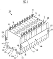
- FIG. 1 is a perspective view of a battery module according to an embodiment of the present invention.
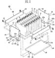
- FIG. 2 is an exploded perspective view of FIG. 1 .
- the battery module 100 includes a plurality of battery cells 10 stacked together and aligned in one direction, first and second end plates 110 and 120 located at either end of the stacked battery cells 10, and side and bottom plates 130 and 140 that connect the first and second end plates 110 and 120 and support both side surfaces of the battery cells 10.
- the first or second end plate 110 or 120 include bent support portions 114 and 124 that overlap at least a portion of the bottom plate 140.
- Each battery cell 10 may be manufactured by accommodating an electrode assembly and an electrolyte in a battery case and then sealing the battery case with a cap plate 14.
- the cap plate 14 includes positive and negative electrode terminals 11 and 12, and a vent 13 located between the terminals 11 and 12.
- the electrode assembly is composed of a positive electrode plate, a negative electrode plate and a separator between electrode plates.
- the positive electrode plate is connected to the positive electrode terminal 11, and the negative electrode plate is connected to the negative electrode terminal 12 so that energy generated by an electrochemical reaction between the electrode assembly and the electrolyte is transferred to the exterior of the battery cell 10.
- the vent 13 serves as a path along which gas generated in the interior of the battery cell 10 can be exhausted to the exterior of the battery cell 10.
- the pair of the first and second end plates 110 and 120 and the side and bottom plates 130 and 140 that connect the first and second end plates 110 and 120 accommodate the plurality of battery cells 10.
- the battery cells 10 are aligned and fixed in one direction within the provided space. In one embodiment, the battery cells 10 are aligned in parallel so that wide planar surfaces of neighbouring battery cells 10 are adjacent to each other.
- the positive and negative electrode terminals 11 and 12 are electrically connected through bus-bars 15.
- Each bus-bar 15 has openings through which the positive and negative electrode terminals 11 and 12 can pass.
- Each bus-bar 15 is connected to the terminals respectively passing through its holes by a nut 16 in this particular embodiment this being one example of a fixing means that may be employed.
- the first and second end plates 110 and 120 are oriented to contact one of the outermost battery cells so that they can together apply a compressive force to the battery cells 10.
- the positive and negative electrode terminals 11 and 12 of the plurality of battery cells 10 supported by the first and second end plates 110 and 120, the side plates 130 and the bottom plate 140 are alternately aligned to be connected in series.
- the first and second end plates 110 and 120, the side plates 130 and the bottom plate 140 constitute a housing for stably fixing the plurality of battery cells 10.
- the housing may be implemented by being variously modified according to the design target of the battery module 100.
- the first and second end plates 110 and 120 include respective base plates 113 and 123 and flange portions 111, 112, and 121, 122.
- the base plates 113 and 123 are oriented parallel to the battery cells 10, and the flange portions 111, 112, 121 and 122 are bent to extend away from the battery cells 10 from at least one edge region of the base plates 113 and 123.
- the base plates 113 and 123 have a size similar to the wide front surface of the battery cell 10 so as to at least partially cover the external shape of the battery cell 10.
- the base plates 113 and 123 have an approximately rectangular shape generally corresponding to the battery cell 10.
- the present invention is not limited thereto.
- the flange portions 111, 112, and 121, 122 include side flange portions 111 and 121 extending from the side portions of the base plates 113 and 123, respectively, and bottom flange portions 112 and 122 extending from the bottom portions of the base plates 113 and 123, respectively.
- the side flange portions 111 and 121 are portions respectively coupled to ends 131, 132 of the side plate 130.
- the coupling force between the side plate 130 and the side flange portions 111 and 121 can be enhanced using bolts 20 or the like
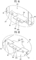
- FIG. 3A is a perspective view showing a state that the end plates are connected to the bottom plate.
- FIG. 3B is a bottom perspective view of a bottom portion of the battery module according to the embodiment of the present invention.
- the first and second end plates 110 and 120 respectively include the bent support portions 114 and 124 that overlap with at least portions of the bottom plate 140.
- the bottom plate 140 connects the first and second end plates 110 and 120 to each other and is provided between the first and second end plates 110 and 120.
- a respective end 141 and 142 of the bottom plate 140 contacts one of the base plates 113 and 123 of the first and second end plates 110 and 120, respectively.
- the flange portions 111, 112, 121 and 122 include at least two lower flange portions 112 and 122, respectively, spaced from each other at the bottom portions of the base plates 113 and 123.
- the bent support portions 114 and 124 are provided between the lower flange portions 112 and 122.
- the bent support portions 114 and 124 are provided so that each of the bent support portions extends from the bottom portion of the first or second end plate 110 or 120 toward the battery cells 10.
- One or more, in this case two, holes 112a and 122a are provided in the respective lower flange portions 112 and 122 for mounting the battery module 10 on a flat part or to fix between neighbouring battery modules.
- the bottom plate 140 supports the load of the plurality battery cells 10, it typically has a higher rigidity than the side plates 130 or the first and second end plates 110 and 120. The fastening force between the bottom plate 140 and the first and second end plates 110 and 120 is sufficient to support the load of the plurality of the battery cells 10.
- the bent support portions 114 and 124 are provided on the respective first and second end plates 110 and 120 so that the bottom plate 140 can distribute the load of the battery cells 10 concentrated on the bottom plate 140 to the first and second end plates 110 and 120. Since stress applied to portions at which the first and second end plates 110 and 120 are fastened to the bottom plate 140 can be distributed, it is possible to improve the stability of the battery module 100 against an external impact such as a vibration or impact.
- the bottom plate 140 is made of a material such as SUS with high rigidity to support the load concentrated on the bottom plate 140.
- the battery module 100 according to this invention is not limited thereto.
- the bottom plate 140 may be made of plastic or the like, which has relatively low rigidity.
- the bottom plate 140 made of a plastic resin material has a lower rigidity than the SUS or the like, but minimizes the weight and size of the battery module and has plasticity, and thus the design of the battery module can be more easily modified.
- the plastic resin bottom plate 140 has excellent insulation properties, and thus the stability of the battery module can be improved.
- the bottom plate 140 contacts the base plates 113 and 123 of the first and second end plates 110 and 120 and it is mounted on the bent support portions 114 and 124 of the first and second plates 110 and 120.
- the first and second end plates 110 and 120 are respectively provided with first fastening holes 113a and 123a at a portion that contacts the one end or the other 141 or 142 of the bottom plate 140.
- the bottom plate 140 has second fastening holes 141a and 142a generally corresponding in position to the first fastening holes 113a and 123.
- the first and second fastening holes 113a, 123a, 141a and 142a are provided so that corresponding first and second fastening holes are aligned with each other.
- the first and second fastening holes 113a, 123a, 141a and 142a 30 receive fixing members 30 to improve the fastening force between the bottom plate 140 and the first and second end plates 110 and 120.
- the fixing members 30 are bolts, but other members such as studs, are possible.
- first and second fastening holes 113a, 123a, 141a and 142a are fastened to be generally perpendicular to the load of the battery cells 10 which is concentrated on the bottom plate 140, the load of the battery cells 10 can be distributed.
- FIGS. 4A to 6B details except the following description are similar to those described in FIGS. 1 to 3B , and therefore, their detailed descriptions will be omitted.
- FIG. 4A is a perspective view of a first end plate and a bottom plate according to this embodiment of the present invention.
- FIG. 4B is a perspective view of a bottom portion of FIG. 4A .
- the bottom plate 240 is provided to contact a base plate 213 of the first end plate 210 and to be mounted on a bent support portion 214 of the first end plate 210.
- the first end plate 210 includes at least one lower flange portion 212 bent away from the battery cells from a bottom portion of the base plate 213.
- the bent support portion 214 includes two bent support portions 214a and 214b spaced from each other.
- the lower flange portion 212 is provided at a central portion of the base plate 213 between the bent support portions 214a and 214b.
- the first end plate 210 includes two bent support portions 214a and 214b, and therefore, the area overlapping with the bottom plate 240 is maximized.
- the load of the battery cells which is concentrated on the bottom plate 240 can be more effectively distributed, thereby stably supporting the battery cells.
- FIG. 5A is a perspective view of a first end plate and a bottom plate according to still another embodiment of the present invention.
- FIG. 5B is a perspective view of a bottom portion of FIG. 5A .
- the bottom plate 340 contacts a base plate 313 of the first end plate 310 and is mounted on a bent support portion 314 of the first end plate 310.
- the width of the bent support portion 314 is substantially identical to the base plate 313.
- the width of the bent support portion 314 is substantially identical to the base plate 313 so that it is possible to effectively distribute a load applied to the bottom plate 340 without a change in the size of the battery module.
- the bent support portion 314 is provided only by bending a bottom portion of the base plate 313 without an additional cutting process so that it is possible to improve process efficiency.
- FIG. 6A is a perspective view of a first end plate and a bottom plate according to still another embodiment of the present invention.
- FIG. 6B is a perspective view of a bottom portion of FIG. 6A .
- the bottom plate 440 is provided to contact a base plate 413 of the first end plate 410 and to be mounted on a bent support portion 414 of the first end plate 410.
- the bent support portion 414 further includes third fastening holes 414a through which the bottom plate 440 is fixed to the bent support portion 414 of the first end plate 410.
- the bottom plate 440 is fastened to the base plate 413 of the first end plate 410, and a fastening portion of the bottom plate 440 is increased by the third fastening holes 414a provided in the bent support portion 414 so that it is possible to improve the fastening force between the first bottom plate 440 and the first end plate 410.
Description
- Embodiments of the present invention relate to a battery module.
- A high-power battery module using a non-aqueous electrolyte with high energy density has recently been developed. The high-power battery module is configured as a large-capacity battery module manufactured by connecting a plurality of battery cells in series so as to be used in driving motors of devices requiring high power, e.g., electric vehicles and the like.
- A battery cell typically includes an electrolyte and an electrode assembly composed of a positive plate and a negative electrode plate, and generates energy through an electrochemical reaction of these electrode plates and the electrolyte. Gas may be generated as a side reaction of the electrochemical reaction in the interior of the battery cell, and the generated gas may change the external shape of the battery cell. Further, the change in the external shape of the battery cell has influence on the shape of a battery module formed by aligning a plurality of battery cells, and therefore, the battery cells may not be firmly fixed in the battery module. Accordingly, various types of battery modules have been developed to minimize a change in the external shape of battery cells and to enhance productivity of the battery modules.
-
US 4,994,940 discloses a cabinet for electrical battery banks comprising battery modules having wheels and shelves for supporting batteries. -
EP 0 952 620 discloses a modular system for accommodating batteries having top and bottom plates and side plates having outwardly bent flanges. - Embodiments of the invention set out to provide a battery module capable of improving reliability by strengthening a housing of the battery module. Embodiments of the invention also set out to provide a battery module capable of minimizing the size and weight of the battery module by distributing the load of a plurality of battery cells.
- Accordingly, the present invention provides a battery module according to claim 1. Optional features of the invention are set out in Claims 2 to 9.
- The following description sets out to, illustrate embodiments of the present invention, and, together with the drawings, serves to explain principles of the present invention.
-
FIG. 1 is a perspective view of a battery module according to an embodiment of the present invention. -
FIG. 2 is an exploded perspective view ofFIG. 1 . -
FIG. 3A is a perspective view showing end plates connected to a bottom plate. -
FIG. 3B is a bottom perspective view of a bottom portion of the battery module according to an embodiment of the present invention. -
FIG. 4A is a perspective view of a first end plate and a bottom plate according to another embodiment of the present invention. -
FIG. 4B is a bottom perspective view of a bottom portion ofFIG. 4A . -
FIG. 5A is a perspective view of a first end plate and a bottom plate according to still another embodiment of the present invention. -
FIG. 5B is a bottom perspective view of a bottom portion ofFIG. 5A . -
FIG. 6A is a perspective view of a first end plate and a bottom plate according to still another embodiment of the present invention. -
FIG. 6B is a bottom perspective view of a bottom portion ofFIG. 6A . - In the following description, only certain embodiments of the present invention have been shown and described by way of illustration. As those skilled in the art would realize, the described embodiments may be modified in various different ways, all without departing from the scope of the present invention. Accordingly, the drawings and description are to be regarded as illustrative in nature and not restrictive. In addition, when an element is referred to as being "on" another element, it can be directly on the another element or be indirectly on the another element with one or more intervening elements interposed therebetween. Also, when an element is referred to as being "connected to" another element, it can be directly connected to the another element or be indirectly connected to the another element with one or more intervening elements interposed therebetween. Hereinafter, like reference numerals refer to like elements.
- Hereinafter, embodiments of the present invention will be described with reference to the accompanying drawings.
- An embodiment of the present invention will be described with reference to
FIGS. 1 to 3B . -
FIG. 1 is a perspective view of a battery module according to an embodiment of the present invention.FIG. 2 is an exploded perspective view ofFIG. 1 . - The
battery module 100 according to this embodiment includes a plurality ofbattery cells 10 stacked together and aligned in one direction, first andsecond end plates battery cells 10, and side andbottom plates second end plates battery cells 10. The first orsecond end plate bent support portions bottom plate 140. - Each
battery cell 10 may be manufactured by accommodating an electrode assembly and an electrolyte in a battery case and then sealing the battery case with acap plate 14. Thecap plate 14 includes positive andnegative electrode terminals 11 and 12, and avent 13 located between theterminals 11 and 12. The electrode assembly is composed of a positive electrode plate, a negative electrode plate and a separator between electrode plates. The positive electrode plate is connected to the positive electrode terminal 11, and the negative electrode plate is connected to thenegative electrode terminal 12 so that energy generated by an electrochemical reaction between the electrode assembly and the electrolyte is transferred to the exterior of thebattery cell 10. Thevent 13 serves as a path along which gas generated in the interior of thebattery cell 10 can be exhausted to the exterior of thebattery cell 10. - The pair of the first and
second end plates bottom plates second end plates battery cells 10. Thebattery cells 10 are aligned and fixed in one direction within the provided space. In one embodiment, thebattery cells 10 are aligned in parallel so that wide planar surfaces of neighbouringbattery cells 10 are adjacent to each other. The positive andnegative electrode terminals 11 and 12 are electrically connected through bus-bars 15. Each bus-bar 15 has openings through which the positive andnegative electrode terminals 11 and 12 can pass. Each bus-bar 15 is connected to the terminals respectively passing through its holes by anut 16 in this particular embodiment this being one example of a fixing means that may be employed. - The first and
second end plates battery cells 10. - In this embodiment, the positive and
negative electrode terminals 11 and 12 of the plurality ofbattery cells 10 supported by the first andsecond end plates side plates 130 and thebottom plate 140 are alternately aligned to be connected in series. - The first and
second end plates side plates 130 and thebottom plate 140 constitute a housing for stably fixing the plurality ofbattery cells 10. The housing may be implemented by being variously modified according to the design target of thebattery module 100. - In this embodiment, the first and
second end plates respective base plates flange portions base plates battery cells 10, and theflange portions battery cells 10 from at least one edge region of thebase plates - The
base plates battery cell 10 so as to at least partially cover the external shape of thebattery cell 10. In this embodiment, thebase plates battery cell 10. However, the present invention is not limited thereto. - The
flange portions side flange portions base plates bottom flange portions base plates side flange portions side plate 130. The coupling force between theside plate 130 and theside flange portions bolts 20 or the like -
FIG. 3A is a perspective view showing a state that the end plates are connected to the bottom plate.FIG. 3B is a bottom perspective view of a bottom portion of the battery module according to the embodiment of the present invention. - Referring to
FIGS. 3A and3B , the first andsecond end plates bent support portions bottom plate 140. Thebottom plate 140 connects the first andsecond end plates second end plates respective end bottom plate 140 contacts one of thebase plates second end plates - In the first and
second end plates flange portions lower flange portions base plates bent support portions lower flange portions bent support portions second end plate battery cells 10. - One or more, in this case two,
holes lower flange portions battery module 10 on a flat part or to fix between neighbouring battery modules. - Since the
bottom plate 140 supports the load of theplurality battery cells 10, it typically has a higher rigidity than theside plates 130 or the first andsecond end plates bottom plate 140 and the first andsecond end plates battery cells 10. - In this embodiment, the
bent support portions second end plates bottom plate 140 can distribute the load of thebattery cells 10 concentrated on thebottom plate 140 to the first andsecond end plates second end plates bottom plate 140 can be distributed, it is possible to improve the stability of thebattery module 100 against an external impact such as a vibration or impact. - Generally, the
bottom plate 140 is made of a material such as SUS with high rigidity to support the load concentrated on thebottom plate 140. However, thebattery module 100 according to this invention is not limited thereto. For example, in thebattery module 100 according to this embodiment, thebottom plate 140 may be made of plastic or the like, which has relatively low rigidity. Thebottom plate 140 made of a plastic resin material has a lower rigidity than the SUS or the like, but minimizes the weight and size of the battery module and has plasticity, and thus the design of the battery module can be more easily modified. Further, the plasticresin bottom plate 140 has excellent insulation properties, and thus the stability of the battery module can be improved. - The
bottom plate 140 contacts thebase plates second end plates bent support portions second plates second end plates first fastening holes bottom plate 140. Thebottom plate 140 hassecond fastening holes first fastening holes - The first and
second fastening holes second fastening holes 142a 30 receive fixingmembers 30 to improve the fastening force between thebottom plate 140 and the first andsecond end plates members 30 are bolts, but other members such as studs, are possible. - Since the first and
second fastening holes battery cells 10 which is concentrated on thebottom plate 140, the load of thebattery cells 10 can be distributed. - Hereinafter, another embodiment of the present invention will be described with reference to
FIGS. 4A to 6B . In this embodiment, details except the following description are similar to those described inFIGS. 1 to 3B , and therefore, their detailed descriptions will be omitted. -
FIG. 4A is a perspective view of a first end plate and a bottom plate according to this embodiment of the present invention.FIG. 4B is a perspective view of a bottom portion ofFIG. 4A . - Referring to
FIGS. 4A and 4B thebottom plate 240 is provided to contact abase plate 213 of thefirst end plate 210 and to be mounted on abent support portion 214 of thefirst end plate 210. - The
first end plate 210 includes at least onelower flange portion 212 bent away from the battery cells from a bottom portion of thebase plate 213. Thebent support portion 214 includes twobent support portions lower flange portion 212 is provided at a central portion of thebase plate 213 between thebent support portions - In this embodiment, the
first end plate 210 includes twobent support portions bottom plate 240 is maximized. Thus, the load of the battery cells which is concentrated on thebottom plate 240 can be more effectively distributed, thereby stably supporting the battery cells. -
FIG. 5A is a perspective view of a first end plate and a bottom plate according to still another embodiment of the present invention.FIG. 5B is a perspective view of a bottom portion ofFIG. 5A . - Referring to
FIGS. 5A and 5B , in a battery module according to this embodiment, thebottom plate 340 contacts abase plate 313 of thefirst end plate 310 and is mounted on abent support portion 314 of thefirst end plate 310. In this instance, the width of thebent support portion 314 is substantially identical to thebase plate 313. - In such a battery module that requires no lower flange portion of the
first end plate 310, the width of thebent support portion 314 is substantially identical to thebase plate 313 so that it is possible to effectively distribute a load applied to thebottom plate 340 without a change in the size of the battery module. Thebent support portion 314 is provided only by bending a bottom portion of thebase plate 313 without an additional cutting process so that it is possible to improve process efficiency. -
FIG. 6A is a perspective view of a first end plate and a bottom plate according to still another embodiment of the present invention.FIG. 6B is a perspective view of a bottom portion ofFIG. 6A . - Referring to
FIGS. 6A and 6B , in a battery module according to this embodiment, thebottom plate 440 is provided to contact abase plate 413 of thefirst end plate 410 and to be mounted on abent support portion 414 of thefirst end plate 410. In this embodiment, thebent support portion 414 further includesthird fastening holes 414a through which thebottom plate 440 is fixed to thebent support portion 414 of thefirst end plate 410. - In the battery module according to this embodiment, the
bottom plate 440 is fastened to thebase plate 413 of thefirst end plate 410, and a fastening portion of thebottom plate 440 is increased by thethird fastening holes 414a provided in thebent support portion 414 so that it is possible to improve the fastening force between thefirst bottom plate 440 and thefirst end plate 410. - While the present invention has been described in connection with certain embodiments, it is to be understood that the invention is not limited to the disclosed embodiments, but, on the contrary, is intended to cover various modifications and equivalent arrangements included within the scope of the appended claims, and equivalents thereof.
Claims (9)
- A battery module comprising:a plurality of battery cells (10) stacked together;first (110) and second (120) end plates located at a first end and a second end, respectively, of the stacked battery cells; andside plates (130) and a bottom plate (140) coupled to the first and second end plates (110, 120) wherein the bottom plate (140) connects the first and second end plates (110, 120) to each other and is located between the first and second end plates;wherein at least one of the first end plate (110) and the second end plate (120) has a bent support portion (114, 124) which extends from a bottom portion of the first or second end plate (110, 120) towards the battery cells (10) such that it overlaps with and supports at least a portion of the bottom plate (140);characterised in that the first and second end plates are each oriented to contact one of the outermost battery cells in the stack, and to apply a compressive force to the battery cells, and the battery cells are positioned on the bottom plate (140) such that the bottom plate supports the load of the battery cells;the first or second end plate (110, 120) has a first fastening hole (113a, 123a) on a portion that contacts an end (141, 142) of the bottom plate (140);the bottom plate has a second fastening hole (141a, 142a) that is aligned with the first fastening hole (113a, 123a); andthe first and second fastening holes (113a, 123a, 141a, 142a) accommodate a fixing member (30).
- A battery module according to claim 1, wherein the fixing member (30) comprises a bolt or a stud.
- A battery module according to claim 1 or 2, wherein the bottom plate (140) comprises plastic resin.
- A battery module according to any preceding claim, wherein the first or second end plate (110, 120) comprises a base plate contacting a peripheral one of the battery cells and at least one flange portion (111, 112, 121, 122) bent away from the battery cells (10) from at least one of a side portion or a bottom portion of the base plate (113, 123).
- A battery module according to claim 4, wherein the bottom plate (140) contacts the base plates of the first and second end plates (110, 120) and is mounted on the bent support portions (114, 124) of at least one of the first end plate or the second end plate (110, 120).
- A battery module according to claim 5, wherein the bent support portion further comprises a third fastening hole (414a) through which a fastener extends to fix the bottom plate to the bent support portion.
- A battery module according to claim 4, 5 or 6, wherein the flange portions comprise at least two lower flange portions (112, 122) spaced from each other on the base plate (113, 123), and wherein the bent support portion (114, 124) is located between the flange portions (112, 122).
- A battery module according to claim 4, 5 or 6, wherein a width of the bent support portion (314) is identical to the base plate (340).
- A battery module according to claim 4, 5, 6 or 7, wherein at least a portion of the flange portion is coupled to an end of the side plate.
Applications Claiming Priority (1)
| Application Number | Priority Date | Filing Date | Title |
|---|---|---|---|
| KR1020110013340A KR101303416B1 (en) | 2011-02-15 | 2011-02-15 | Battery module providing improved housing |
Publications (2)
| Publication Number | Publication Date |
|---|---|
| EP2490277A1 EP2490277A1 (en) | 2012-08-22 |
| EP2490277B1 true EP2490277B1 (en) | 2018-08-22 |
Family
ID=44802545
Family Applications (1)
| Application Number | Title | Priority Date | Filing Date |
|---|---|---|---|
| EP11172431.6A Active EP2490277B1 (en) | 2011-02-15 | 2011-07-01 | Battery Module |
Country Status (3)
| Country | Link |
|---|---|
| US (1) | US8623535B2 (en) |
| EP (1) | EP2490277B1 (en) |
| KR (1) | KR101303416B1 (en) |
Families Citing this family (6)
| Publication number | Priority date | Publication date | Assignee | Title |
|---|---|---|---|---|
| KR101117686B1 (en) * | 2009-12-28 | 2012-02-29 | 에스비리모티브 주식회사 | Battery module and battery pack having the same |
| JP6224321B2 (en) * | 2013-01-11 | 2017-11-01 | フタバ産業株式会社 | Battery assembly restraint, battery assembly restraint member, battery |
| KR101729553B1 (en) * | 2013-08-23 | 2017-04-24 | 주식회사 엘지화학 | Battery Pack for Electric Power Storage Device |
| JP6414731B2 (en) * | 2013-10-01 | 2018-10-31 | 株式会社Gsユアサ | Power storage element and power storage device |
| KR102411156B1 (en) | 2015-12-29 | 2022-06-21 | 에이치그린파워 주식회사 | Extensible stack module housing and Battery module having the same |
| KR102394698B1 (en) | 2016-11-08 | 2022-05-09 | 삼성에스디아이 주식회사 | battery pack |
Citations (11)
| Publication number | Priority date | Publication date | Assignee | Title |
|---|---|---|---|---|
| EP2323194A1 (en) * | 2009-11-16 | 2011-05-18 | SB LiMotive Co., Ltd. | Battery module having improved end plate |
| EP2325922A1 (en) * | 2009-11-19 | 2011-05-25 | SB LiMotive Co., Ltd. | Battery pack |
| EP2325923A1 (en) * | 2009-11-19 | 2011-05-25 | SB LiMotive Co., Ltd. | Battery pack with improved stability |
| EP2328201A1 (en) * | 2009-11-05 | 2011-06-01 | SB LiMotive Co., Ltd. | Battery Pack |
| EP2330657A1 (en) * | 2009-12-04 | 2011-06-08 | SB LiMotive Co., Ltd. | Battery module and battery pack including the same |
| EP2337113A1 (en) * | 2009-12-18 | 2011-06-22 | SB LiMotive Co., Ltd. | Battery module having restrainer and method of fixing restrainer |
| EP2339664A1 (en) * | 2009-12-23 | 2011-06-29 | SB LiMotive Co., Ltd. | Battery pack |
| EP2341569A1 (en) * | 2010-01-05 | 2011-07-06 | SB LiMotive Co., Ltd. | Battery Pack |
| EP2381506A1 (en) * | 2010-04-21 | 2011-10-26 | SB LiMotive Co., Ltd. | Battery module |
| EP2381507A1 (en) * | 2010-04-21 | 2011-10-26 | SB LiMotive Co., Ltd. | Battery pack |
| EP2390945A1 (en) * | 2010-05-24 | 2011-11-30 | SB LiMotive Co., Ltd. | Battery module |
Family Cites Families (11)
| Publication number | Priority date | Publication date | Assignee | Title |
|---|---|---|---|---|
| FR2637155A1 (en) | 1988-09-29 | 1990-03-30 | Merlin Gerin | MODULAR CABINET FOR ELECTRICAL BATTERIES |
| KR19980056884A (en) * | 1996-12-30 | 1998-09-25 | 김영귀 | Car Battery Carrier |
| US6326103B1 (en) | 1998-03-25 | 2001-12-04 | Matsushita Electric Industrial Co., Ltd. | Sealed storage battery and modular system therefor |
| JP4833420B2 (en) * | 2000-02-25 | 2011-12-07 | パナソニック株式会社 | Battery pack |
| JP4136328B2 (en) * | 2001-05-14 | 2008-08-20 | トヨタ自動車株式会社 | Battery restraint device |
| US7323271B2 (en) * | 2003-08-27 | 2008-01-29 | Kim Manufacturing Company | Front access battery tray apparatus and system |
| US20090092876A1 (en) | 2005-05-13 | 2009-04-09 | Hideaki Yasui | Fuel cell |
| KR100919390B1 (en) * | 2006-02-13 | 2009-09-29 | 주식회사 엘지화학 | Medium and Large Size Battery Module of Vertical Stacking Structure |
| JP5082568B2 (en) | 2007-04-26 | 2012-11-28 | トヨタ自動車株式会社 | Power storage device |
| KR101141057B1 (en) | 2007-06-28 | 2012-05-03 | 주식회사 엘지화학 | Middle or Large-sized Battery Pack |
| BRPI1014493A2 (en) | 2009-04-24 | 2016-04-05 | Nissan Motor | battery pack |
-
2011
- 2011-02-15 KR KR1020110013340A patent/KR101303416B1/en active IP Right Grant
- 2011-05-18 US US13/110,658 patent/US8623535B2/en active Active
- 2011-07-01 EP EP11172431.6A patent/EP2490277B1/en active Active
Patent Citations (11)
| Publication number | Priority date | Publication date | Assignee | Title |
|---|---|---|---|---|
| EP2328201A1 (en) * | 2009-11-05 | 2011-06-01 | SB LiMotive Co., Ltd. | Battery Pack |
| EP2323194A1 (en) * | 2009-11-16 | 2011-05-18 | SB LiMotive Co., Ltd. | Battery module having improved end plate |
| EP2325922A1 (en) * | 2009-11-19 | 2011-05-25 | SB LiMotive Co., Ltd. | Battery pack |
| EP2325923A1 (en) * | 2009-11-19 | 2011-05-25 | SB LiMotive Co., Ltd. | Battery pack with improved stability |
| EP2330657A1 (en) * | 2009-12-04 | 2011-06-08 | SB LiMotive Co., Ltd. | Battery module and battery pack including the same |
| EP2337113A1 (en) * | 2009-12-18 | 2011-06-22 | SB LiMotive Co., Ltd. | Battery module having restrainer and method of fixing restrainer |
| EP2339664A1 (en) * | 2009-12-23 | 2011-06-29 | SB LiMotive Co., Ltd. | Battery pack |
| EP2341569A1 (en) * | 2010-01-05 | 2011-07-06 | SB LiMotive Co., Ltd. | Battery Pack |
| EP2381506A1 (en) * | 2010-04-21 | 2011-10-26 | SB LiMotive Co., Ltd. | Battery module |
| EP2381507A1 (en) * | 2010-04-21 | 2011-10-26 | SB LiMotive Co., Ltd. | Battery pack |
| EP2390945A1 (en) * | 2010-05-24 | 2011-11-30 | SB LiMotive Co., Ltd. | Battery module |
Also Published As
| Publication number | Publication date |
|---|---|
| KR20120093646A (en) | 2012-08-23 |
| KR101303416B1 (en) | 2013-09-05 |
| US20120208069A1 (en) | 2012-08-16 |
| EP2490277A1 (en) | 2012-08-22 |
| US8623535B2 (en) | 2014-01-07 |
Similar Documents
| Publication | Publication Date | Title |
|---|---|---|
| EP2521204B1 (en) | Battery module | |
| US8956751B2 (en) | Battery pack and battery module having the same | |
| US9859544B2 (en) | Battery module | |
| EP2418710B1 (en) | Battery module | |
| JP6088185B2 (en) | Battery module | |
| EP2631965B1 (en) | Battery module | |
| US8232000B2 (en) | Rechargeable battery with terminal junction and prong | |
| EP2645454B1 (en) | Bus bar assembly having a novel structure | |
| EP2515360B1 (en) | Battery module | |
| US9166260B2 (en) | Battery module | |
| US9570721B2 (en) | Battery module | |
| US9083030B2 (en) | Battery module | |
| US9012063B2 (en) | Battery module | |
| US9012068B2 (en) | Battery cell and battery module using the same | |
| EP2490277B1 (en) | Battery Module | |
| US9419262B2 (en) | Battery module | |
| US10367180B2 (en) | Battery pack |
Legal Events
| Date | Code | Title | Description |
|---|---|---|---|
| PUAI | Public reference made under article 153(3) epc to a published international application that has entered the european phase |
Free format text: ORIGINAL CODE: 0009012 |
|
| 17P | Request for examination filed |
Effective date: 20120329 |
|
| AK | Designated contracting states |
Kind code of ref document: A1 Designated state(s): AL AT BE BG CH CY CZ DE DK EE ES FI FR GB GR HR HU IE IS IT LI LT LU LV MC MK MT NL NO PL PT RO RS SE SI SK SM TR |
|
| AX | Request for extension of the european patent |
Extension state: BA ME |
|
| RAP1 | Party data changed (applicant data changed or rights of an application transferred) |
Owner name: SAMSUNG SDI CO., LTD. Owner name: ROBERT BOSCH GMBH |
|
| 17Q | First examination report despatched |
Effective date: 20130128 |
|
| STAA | Information on the status of an ep patent application or granted ep patent |
Free format text: STATUS: EXAMINATION IS IN PROGRESS |
|
| GRAP | Despatch of communication of intention to grant a patent |
Free format text: ORIGINAL CODE: EPIDOSNIGR1 |
|
| STAA | Information on the status of an ep patent application or granted ep patent |
Free format text: STATUS: GRANT OF PATENT IS INTENDED |
|
| INTG | Intention to grant announced |
Effective date: 20180129 |
|
| GRAS | Grant fee paid |
Free format text: ORIGINAL CODE: EPIDOSNIGR3 |
|
| GRAA | (expected) grant |
Free format text: ORIGINAL CODE: 0009210 |
|
| STAA | Information on the status of an ep patent application or granted ep patent |
Free format text: STATUS: THE PATENT HAS BEEN GRANTED |
|
| AK | Designated contracting states |
Kind code of ref document: B1 Designated state(s): AL AT BE BG CH CY CZ DE DK EE ES FI FR GB GR HR HU IE IS IT LI LT LU LV MC MK MT NL NO PL PT RO RS SE SI SK SM TR |
|
| REG | Reference to a national code |
Ref country code: GB Ref legal event code: FG4D |
|
| REG | Reference to a national code |
Ref country code: CH Ref legal event code: EP |
|
| REG | Reference to a national code |
Ref country code: AT Ref legal event code: REF Ref document number: 1033488 Country of ref document: AT Kind code of ref document: T Effective date: 20180915 |
|
| REG | Reference to a national code |
Ref country code: IE Ref legal event code: FG4D |
|
| REG | Reference to a national code |
Ref country code: DE Ref legal event code: R096 Ref document number: 602011051237 Country of ref document: DE |
|
| REG | Reference to a national code |
Ref country code: NL Ref legal event code: MP Effective date: 20180822 |
|
| REG | Reference to a national code |
Ref country code: LT Ref legal event code: MG4D |
|
| PG25 | Lapsed in a contracting state [announced via postgrant information from national office to epo] |
Ref country code: BG Free format text: LAPSE BECAUSE OF FAILURE TO SUBMIT A TRANSLATION OF THE DESCRIPTION OR TO PAY THE FEE WITHIN THE PRESCRIBED TIME-LIMIT Effective date: 20181122 Ref country code: NL Free format text: LAPSE BECAUSE OF FAILURE TO SUBMIT A TRANSLATION OF THE DESCRIPTION OR TO PAY THE FEE WITHIN THE PRESCRIBED TIME-LIMIT Effective date: 20180822 Ref country code: LT Free format text: LAPSE BECAUSE OF FAILURE TO SUBMIT A TRANSLATION OF THE DESCRIPTION OR TO PAY THE FEE WITHIN THE PRESCRIBED TIME-LIMIT Effective date: 20180822 Ref country code: IS Free format text: LAPSE BECAUSE OF FAILURE TO SUBMIT A TRANSLATION OF THE DESCRIPTION OR TO PAY THE FEE WITHIN THE PRESCRIBED TIME-LIMIT Effective date: 20181222 Ref country code: SE Free format text: LAPSE BECAUSE OF FAILURE TO SUBMIT A TRANSLATION OF THE DESCRIPTION OR TO PAY THE FEE WITHIN THE PRESCRIBED TIME-LIMIT Effective date: 20180822 Ref country code: NO Free format text: LAPSE BECAUSE OF FAILURE TO SUBMIT A TRANSLATION OF THE DESCRIPTION OR TO PAY THE FEE WITHIN THE PRESCRIBED TIME-LIMIT Effective date: 20181122 Ref country code: FI Free format text: LAPSE BECAUSE OF FAILURE TO SUBMIT A TRANSLATION OF THE DESCRIPTION OR TO PAY THE FEE WITHIN THE PRESCRIBED TIME-LIMIT Effective date: 20180822 Ref country code: RS Free format text: LAPSE BECAUSE OF FAILURE TO SUBMIT A TRANSLATION OF THE DESCRIPTION OR TO PAY THE FEE WITHIN THE PRESCRIBED TIME-LIMIT Effective date: 20180822 Ref country code: GR Free format text: LAPSE BECAUSE OF FAILURE TO SUBMIT A TRANSLATION OF THE DESCRIPTION OR TO PAY THE FEE WITHIN THE PRESCRIBED TIME-LIMIT Effective date: 20181123 |
|
| REG | Reference to a national code |
Ref country code: AT Ref legal event code: MK05 Ref document number: 1033488 Country of ref document: AT Kind code of ref document: T Effective date: 20180822 |
|
| PG25 | Lapsed in a contracting state [announced via postgrant information from national office to epo] |
Ref country code: HR Free format text: LAPSE BECAUSE OF FAILURE TO SUBMIT A TRANSLATION OF THE DESCRIPTION OR TO PAY THE FEE WITHIN THE PRESCRIBED TIME-LIMIT Effective date: 20180822 Ref country code: LV Free format text: LAPSE BECAUSE OF FAILURE TO SUBMIT A TRANSLATION OF THE DESCRIPTION OR TO PAY THE FEE WITHIN THE PRESCRIBED TIME-LIMIT Effective date: 20180822 Ref country code: AL Free format text: LAPSE BECAUSE OF FAILURE TO SUBMIT A TRANSLATION OF THE DESCRIPTION OR TO PAY THE FEE WITHIN THE PRESCRIBED TIME-LIMIT Effective date: 20180822 |
|
| PG25 | Lapsed in a contracting state [announced via postgrant information from national office to epo] |
Ref country code: AT Free format text: LAPSE BECAUSE OF FAILURE TO SUBMIT A TRANSLATION OF THE DESCRIPTION OR TO PAY THE FEE WITHIN THE PRESCRIBED TIME-LIMIT Effective date: 20180822 Ref country code: EE Free format text: LAPSE BECAUSE OF FAILURE TO SUBMIT A TRANSLATION OF THE DESCRIPTION OR TO PAY THE FEE WITHIN THE PRESCRIBED TIME-LIMIT Effective date: 20180822 Ref country code: IT Free format text: LAPSE BECAUSE OF FAILURE TO SUBMIT A TRANSLATION OF THE DESCRIPTION OR TO PAY THE FEE WITHIN THE PRESCRIBED TIME-LIMIT Effective date: 20180822 Ref country code: CZ Free format text: LAPSE BECAUSE OF FAILURE TO SUBMIT A TRANSLATION OF THE DESCRIPTION OR TO PAY THE FEE WITHIN THE PRESCRIBED TIME-LIMIT Effective date: 20180822 Ref country code: RO Free format text: LAPSE BECAUSE OF FAILURE TO SUBMIT A TRANSLATION OF THE DESCRIPTION OR TO PAY THE FEE WITHIN THE PRESCRIBED TIME-LIMIT Effective date: 20180822 Ref country code: ES Free format text: LAPSE BECAUSE OF FAILURE TO SUBMIT A TRANSLATION OF THE DESCRIPTION OR TO PAY THE FEE WITHIN THE PRESCRIBED TIME-LIMIT Effective date: 20180822 Ref country code: PL Free format text: LAPSE BECAUSE OF FAILURE TO SUBMIT A TRANSLATION OF THE DESCRIPTION OR TO PAY THE FEE WITHIN THE PRESCRIBED TIME-LIMIT Effective date: 20180822 |
|
| REG | Reference to a national code |
Ref country code: DE Ref legal event code: R097 Ref document number: 602011051237 Country of ref document: DE |
|
| PG25 | Lapsed in a contracting state [announced via postgrant information from national office to epo] |
Ref country code: SM Free format text: LAPSE BECAUSE OF FAILURE TO SUBMIT A TRANSLATION OF THE DESCRIPTION OR TO PAY THE FEE WITHIN THE PRESCRIBED TIME-LIMIT Effective date: 20180822 Ref country code: SK Free format text: LAPSE BECAUSE OF FAILURE TO SUBMIT A TRANSLATION OF THE DESCRIPTION OR TO PAY THE FEE WITHIN THE PRESCRIBED TIME-LIMIT Effective date: 20180822 Ref country code: DK Free format text: LAPSE BECAUSE OF FAILURE TO SUBMIT A TRANSLATION OF THE DESCRIPTION OR TO PAY THE FEE WITHIN THE PRESCRIBED TIME-LIMIT Effective date: 20180822 |
|
| PLBE | No opposition filed within time limit |
Free format text: ORIGINAL CODE: 0009261 |
|
| STAA | Information on the status of an ep patent application or granted ep patent |
Free format text: STATUS: NO OPPOSITION FILED WITHIN TIME LIMIT |
|
| 26N | No opposition filed |
Effective date: 20190523 |
|
| PG25 | Lapsed in a contracting state [announced via postgrant information from national office to epo] |
Ref country code: SI Free format text: LAPSE BECAUSE OF FAILURE TO SUBMIT A TRANSLATION OF THE DESCRIPTION OR TO PAY THE FEE WITHIN THE PRESCRIBED TIME-LIMIT Effective date: 20180822 |
|
| PG25 | Lapsed in a contracting state [announced via postgrant information from national office to epo] |
Ref country code: MC Free format text: LAPSE BECAUSE OF FAILURE TO SUBMIT A TRANSLATION OF THE DESCRIPTION OR TO PAY THE FEE WITHIN THE PRESCRIBED TIME-LIMIT Effective date: 20180822 |
|
| REG | Reference to a national code |
Ref country code: CH Ref legal event code: PL |
|
| PG25 | Lapsed in a contracting state [announced via postgrant information from national office to epo] |
Ref country code: TR Free format text: LAPSE BECAUSE OF FAILURE TO SUBMIT A TRANSLATION OF THE DESCRIPTION OR TO PAY THE FEE WITHIN THE PRESCRIBED TIME-LIMIT Effective date: 20180822 |
|
| REG | Reference to a national code |
Ref country code: BE Ref legal event code: MM Effective date: 20190731 |
|
| PG25 | Lapsed in a contracting state [announced via postgrant information from national office to epo] |
Ref country code: BE Free format text: LAPSE BECAUSE OF NON-PAYMENT OF DUE FEES Effective date: 20190731 Ref country code: CH Free format text: LAPSE BECAUSE OF NON-PAYMENT OF DUE FEES Effective date: 20190731 Ref country code: LI Free format text: LAPSE BECAUSE OF NON-PAYMENT OF DUE FEES Effective date: 20190731 Ref country code: LU Free format text: LAPSE BECAUSE OF NON-PAYMENT OF DUE FEES Effective date: 20190701 |
|
| PG25 | Lapsed in a contracting state [announced via postgrant information from national office to epo] |
Ref country code: PT Free format text: LAPSE BECAUSE OF FAILURE TO SUBMIT A TRANSLATION OF THE DESCRIPTION OR TO PAY THE FEE WITHIN THE PRESCRIBED TIME-LIMIT Effective date: 20181222 |
|
| PG25 | Lapsed in a contracting state [announced via postgrant information from national office to epo] |
Ref country code: IE Free format text: LAPSE BECAUSE OF NON-PAYMENT OF DUE FEES Effective date: 20190701 |
|
| REG | Reference to a national code |
Ref country code: DE Ref legal event code: R079 Ref document number: 602011051237 Country of ref document: DE Free format text: PREVIOUS MAIN CLASS: H01M0002100000 Ipc: H01M0050200000 |
|
| PG25 | Lapsed in a contracting state [announced via postgrant information from national office to epo] |
Ref country code: CY Free format text: LAPSE BECAUSE OF FAILURE TO SUBMIT A TRANSLATION OF THE DESCRIPTION OR TO PAY THE FEE WITHIN THE PRESCRIBED TIME-LIMIT Effective date: 20180822 |
|
| PG25 | Lapsed in a contracting state [announced via postgrant information from national office to epo] |
Ref country code: MT Free format text: LAPSE BECAUSE OF FAILURE TO SUBMIT A TRANSLATION OF THE DESCRIPTION OR TO PAY THE FEE WITHIN THE PRESCRIBED TIME-LIMIT Effective date: 20180822 Ref country code: HU Free format text: LAPSE BECAUSE OF FAILURE TO SUBMIT A TRANSLATION OF THE DESCRIPTION OR TO PAY THE FEE WITHIN THE PRESCRIBED TIME-LIMIT; INVALID AB INITIO Effective date: 20110701 |
|
| PG25 | Lapsed in a contracting state [announced via postgrant information from national office to epo] |
Ref country code: MK Free format text: LAPSE BECAUSE OF FAILURE TO SUBMIT A TRANSLATION OF THE DESCRIPTION OR TO PAY THE FEE WITHIN THE PRESCRIBED TIME-LIMIT Effective date: 20180822 |
|
| P01 | Opt-out of the competence of the unified patent court (upc) registered |
Effective date: 20230530 |
|
| PGFP | Annual fee paid to national office [announced via postgrant information from national office to epo] |
Ref country code: GB Payment date: 20230622 Year of fee payment: 13 |
|
| PGFP | Annual fee paid to national office [announced via postgrant information from national office to epo] |
Ref country code: FR Payment date: 20230703 Year of fee payment: 13 Ref country code: DE Payment date: 20230627 Year of fee payment: 13 |