EP2328201A1 - Battery Pack - Google Patents
Battery Pack Download PDFInfo
- Publication number
- EP2328201A1 EP2328201A1 EP10189920A EP10189920A EP2328201A1 EP 2328201 A1 EP2328201 A1 EP 2328201A1 EP 10189920 A EP10189920 A EP 10189920A EP 10189920 A EP10189920 A EP 10189920A EP 2328201 A1 EP2328201 A1 EP 2328201A1
- Authority
- EP
- European Patent Office
- Prior art keywords
- battery
- plate
- battery pack
- base plate
- flange unit
- Prior art date
- Legal status (The legal status is an assumption and is not a legal conclusion. Google has not performed a legal analysis and makes no representation as to the accuracy of the status listed.)
- Granted
Links
- 230000002787 reinforcement Effects 0.000 claims description 37
- 238000009413 insulation Methods 0.000 claims description 8
- 238000000034 method Methods 0.000 description 9
- 238000005520 cutting process Methods 0.000 description 2
- 239000011810 insulating material Substances 0.000 description 2
- WHXSMMKQMYFTQS-UHFFFAOYSA-N Lithium Chemical compound [Li] WHXSMMKQMYFTQS-UHFFFAOYSA-N 0.000 description 1
- 229910052744 lithium Inorganic materials 0.000 description 1
- 238000004519 manufacturing process Methods 0.000 description 1
- 239000007769 metal material Substances 0.000 description 1
- 229920000642 polymer Polymers 0.000 description 1
- 239000002952 polymeric resin Substances 0.000 description 1
- 230000003014 reinforcing effect Effects 0.000 description 1
- 229920003002 synthetic resin Polymers 0.000 description 1
- 238000003466 welding Methods 0.000 description 1
Images


Classifications
-
- H—ELECTRICITY
- H01—ELECTRIC ELEMENTS
- H01M—PROCESSES OR MEANS, e.g. BATTERIES, FOR THE DIRECT CONVERSION OF CHEMICAL ENERGY INTO ELECTRICAL ENERGY
- H01M50/00—Constructional details or processes of manufacture of the non-active parts of electrochemical cells other than fuel cells, e.g. hybrid cells
- H01M50/20—Mountings; Secondary casings or frames; Racks, modules or packs; Suspension devices; Shock absorbers; Transport or carrying devices; Holders
- H01M50/204—Racks, modules or packs for multiple batteries or multiple cells
- H01M50/207—Racks, modules or packs for multiple batteries or multiple cells characterised by their shape
- H01M50/209—Racks, modules or packs for multiple batteries or multiple cells characterised by their shape adapted for prismatic or rectangular cells
-
- H—ELECTRICITY
- H01—ELECTRIC ELEMENTS
- H01M—PROCESSES OR MEANS, e.g. BATTERIES, FOR THE DIRECT CONVERSION OF CHEMICAL ENERGY INTO ELECTRICAL ENERGY
- H01M50/00—Constructional details or processes of manufacture of the non-active parts of electrochemical cells other than fuel cells, e.g. hybrid cells
- H01M50/30—Arrangements for facilitating escape of gases
- H01M50/394—Gas-pervious parts or elements
-
- H—ELECTRICITY
- H01—ELECTRIC ELEMENTS
- H01M—PROCESSES OR MEANS, e.g. BATTERIES, FOR THE DIRECT CONVERSION OF CHEMICAL ENERGY INTO ELECTRICAL ENERGY
- H01M50/00—Constructional details or processes of manufacture of the non-active parts of electrochemical cells other than fuel cells, e.g. hybrid cells
- H01M50/20—Mountings; Secondary casings or frames; Racks, modules or packs; Suspension devices; Shock absorbers; Transport or carrying devices; Holders
- H01M50/233—Mountings; Secondary casings or frames; Racks, modules or packs; Suspension devices; Shock absorbers; Transport or carrying devices; Holders characterised by physical properties of casings or racks, e.g. dimensions
- H01M50/24—Mountings; Secondary casings or frames; Racks, modules or packs; Suspension devices; Shock absorbers; Transport or carrying devices; Holders characterised by physical properties of casings or racks, e.g. dimensions adapted for protecting batteries from their environment, e.g. from corrosion
-
- H—ELECTRICITY
- H01—ELECTRIC ELEMENTS
- H01M—PROCESSES OR MEANS, e.g. BATTERIES, FOR THE DIRECT CONVERSION OF CHEMICAL ENERGY INTO ELECTRICAL ENERGY
- H01M50/00—Constructional details or processes of manufacture of the non-active parts of electrochemical cells other than fuel cells, e.g. hybrid cells
- H01M50/20—Mountings; Secondary casings or frames; Racks, modules or packs; Suspension devices; Shock absorbers; Transport or carrying devices; Holders
- H01M50/244—Secondary casings; Racks; Suspension devices; Carrying devices; Holders characterised by their mounting method
-
- H—ELECTRICITY
- H01—ELECTRIC ELEMENTS
- H01M—PROCESSES OR MEANS, e.g. BATTERIES, FOR THE DIRECT CONVERSION OF CHEMICAL ENERGY INTO ELECTRICAL ENERGY
- H01M50/00—Constructional details or processes of manufacture of the non-active parts of electrochemical cells other than fuel cells, e.g. hybrid cells
- H01M50/20—Mountings; Secondary casings or frames; Racks, modules or packs; Suspension devices; Shock absorbers; Transport or carrying devices; Holders
- H01M50/262—Mountings; Secondary casings or frames; Racks, modules or packs; Suspension devices; Shock absorbers; Transport or carrying devices; Holders with fastening means, e.g. locks
- H01M50/264—Mountings; Secondary casings or frames; Racks, modules or packs; Suspension devices; Shock absorbers; Transport or carrying devices; Holders with fastening means, e.g. locks for cells or batteries, e.g. straps, tie rods or peripheral frames
-
- Y—GENERAL TAGGING OF NEW TECHNOLOGICAL DEVELOPMENTS; GENERAL TAGGING OF CROSS-SECTIONAL TECHNOLOGIES SPANNING OVER SEVERAL SECTIONS OF THE IPC; TECHNICAL SUBJECTS COVERED BY FORMER USPC CROSS-REFERENCE ART COLLECTIONS [XRACs] AND DIGESTS
- Y02—TECHNOLOGIES OR APPLICATIONS FOR MITIGATION OR ADAPTATION AGAINST CLIMATE CHANGE
- Y02E—REDUCTION OF GREENHOUSE GAS [GHG] EMISSIONS, RELATED TO ENERGY GENERATION, TRANSMISSION OR DISTRIBUTION
- Y02E60/00—Enabling technologies; Technologies with a potential or indirect contribution to GHG emissions mitigation
- Y02E60/10—Energy storage using batteries
-
- Y—GENERAL TAGGING OF NEW TECHNOLOGICAL DEVELOPMENTS; GENERAL TAGGING OF CROSS-SECTIONAL TECHNOLOGIES SPANNING OVER SEVERAL SECTIONS OF THE IPC; TECHNICAL SUBJECTS COVERED BY FORMER USPC CROSS-REFERENCE ART COLLECTIONS [XRACs] AND DIGESTS
- Y02—TECHNOLOGIES OR APPLICATIONS FOR MITIGATION OR ADAPTATION AGAINST CLIMATE CHANGE
- Y02P—CLIMATE CHANGE MITIGATION TECHNOLOGIES IN THE PRODUCTION OR PROCESSING OF GOODS
- Y02P70/00—Climate change mitigation technologies in the production process for final industrial or consumer products
- Y02P70/50—Manufacturing or production processes characterised by the final manufactured product
Definitions
- One or more embodiments of the present invention relate to a battery pack in which a plurality of stacked battery modules are connected to each other.
- Secondary batteries are chargeable and dischargeable. Secondary batteries are used as energy sources of mobile devices, electric vehicles, hybrid electric vehicles, electric bicycles, uninterruptible power supplies, etc.
- small devices such as the mobile devices use a small number of battery cells.
- medium or large devices such as the electric vehicles and hybrid electric vehicle require high power and large capacity and thus use a battery pack in which a plurality of battery cells are electrically connected to each other.
- a plurality of battery cells is connected in series or in parallel so as to be included in a battery unit.
- a plurality of battery units is connected to form a battery module.
- a plurality of battery modules are connected to form a battery pack in order to provide higher power and larger capacity.
- the battery modules When a battery pack is assembled by using a plurality of battery modules, the battery modules need to be firmly connected to each other so as to achieve a stable structure of the battery pack.
- One or more embodiments of the present invention include a battery pack capable of easily connecting a plurality of stacked battery modules to each other.
- a battery pack comprising a plurality of battery modules.
- Each battery module comprises a plurality of battery units arranged along a first direction (Y), a first end plate and a second end plate.
- the plurality of battery units is arranged between the first and second end plate, wherein the first and second end plates are fixed to each other or are fixed to the plurality of battery units.
- the battery pack being characterized in that a first or second end plate of a first battery module is fixed to a first or second end plate of a second battery module being adjacent to the first battery module in order to connect adjacent battery modules of the battery pack.
- the first and second end plates of the battery pack of the invention can be fixed to each other by a first guide plate arranged along said first direction (Y) on a first side surface of the plurality of battery units and coupled to the first and second end plate, and by a second guide plate arranged along said first direction (Y) on a second side surface of the plurality of battery units being opposite to said first side surface and coupled to the first and second end plates.
- the first and second end plates of the battery pack of the invention can comprise a base plate and at least one flange unit extending from the base plate to combine different end plates with each other and/or to fix the guide plates thereto.
- the at least one flange unit can extend from side surfaces of the base plate in a direction away from the plurality of battery units.
- a battery module of the battery pack of the invention may further comprise at least one of a first reinforcement plate mounted on a third side surface of the plurality of battery units, extending in the first direction (Y) and coupled to the first and second end plates; and a second reinforcement plate mounted on a fourth side surface of the plurality of battery units opposite the third side surface, extending in the first direction (Y) and coupled to the first and second end plates.
- said first reinforcement plate may comprise a first base plate on the third side of the plurality of battery units and first bent portions extending from sides of the first base plate away from the plurality of battery units
- said second reinforcement plate may comprise a second base plate on the fourth side of the plurality of battery units and second bent portions extending from sides of the second base plate away from the plurality of battery units.
- said first reinforcement plate of a first battery module may be combined to said second reinforcement plate of a second, adjacent battery module such that a gas discharge path is formed.
- An insulation plate can be mounted on a surface of the first and/or second base plate facing the battery module to which the respective reinforcement plate is mounted.
- the at least one flange unit may comprise a first flange unit extending from a first side of the base plate, a second flange unit extending from a second side of the base plate, the second side being opposite to the first side, a third flange unit extending from a third side of the base plate, and a fourth flange unit extending from a fourth side of the base plate, the fourth side being opposite to the third side.
- the first guide plate may be attached to the first flange unit and the second guide plate may be attached to the second flange unit.
- first reinforcement plate may be attached to the third flange unit and the second reinforcement plate may be attached to the fourth flange unit.
- the third flange unit can comprises a reduced height part adapted to receive said first reinforcement plate of the respective battery module and a second reinforcement plate of a neighboring battery module.
- the at least one flange unit can comprise combination holes to combine different end plates with each other.
- Connecting elements may be used to combine the combination holes of different end plates.
- Connecting elements being nuts and bolts can be used to combine the combination holes of different end plates.
- the first and second guide plates may comprise heat-radiating holes.
- FIG. 1 is a perspective view of a battery module, according to an embodiment of the present invention.
- FIG. 2 is a perspective view of an end plate of the battery module illustrated in FIG. 1 , according to an embodiment of the present invention
- FIG. 3 is a magnified perspective view of a plurality of end plates illustrated in FIG. 1 when the end plates are connected, according to an embodiment of the present invention
- FIG. 4 is a magnified perspective view of one of the end plates illustrated in FIG. 3 when the end plate is mounted, according to an embodiment of the present invention
- FIG. 5 is a front view of the end plate illustrated in FIG. 4 , according to an embodiment of the present invention.
- FIG. 6 is a perspective view of a battery pack in which a plurality of battery modules illustrated in FIG. 1 are stacked, according to an embodiment of the present invention.
- FIG. 1 is a perspective view of a battery module 100, according to an embodiment of the present invention.
- the battery module 100 includes a plurality of battery units 101.
- the battery units 101 are sequentially arranged along a horizontal direction (Y direction).
- the battery units 101 may be sequentially arranged along a vertical direction (Z direction).
- the structure of the battery units 101 is not limited to any one structure as long as the battery units 101 are stacked in one direction.
- a plurality of battery cells is stacked in every battery unit 101 and is accommodated in a case 102.
- a secondary battery such as a general lithium secondary battery may be used as a battery cell.
- the battery cell may be a cylindrical secondary battery, an angular secondary battery, or a polymer secondary battery and is not limited to any one secondary battery.
- the battery cells are electrically connected by using positive and negative electrode tabs that are respectively and electrically connected to positive and negative terminals 103 and 104 that protrude from the case 102.
- the battery cells may be connected in parallel, in series, or in parallel and series and the connection method of the battery cells is not limited to any one connection method.
- the battery units 101 are arranged so that polarities of neighboring battery units 101 are opposite to each other.
- the positive terminal 103 of one battery unit 101 is connected to the negative terminal 104 of a neighboring battery unit 101 by using a bus bar 105.
- the battery units 101 are sequentially connected to form one battery module 100.
- the number of battery units 101 may be determined in consideration of charge and discharge capacities required to design the battery module 100.
- a pair of end plates 108 are separately mounted at outermost sides of the battery module 100.
- the end plates 108 include a first end plate 106 mounted at one end of the battery module 100 and a second end plate 107 mounted at the other end of the battery module 100.
- One surface of the first end plate 106 and one surface of the second end plate 107 separately contact outer surfaces of the battery units 101 arranged at the outermost sides of the battery module 100.
- the first and second end plates 106 and 107 are combined by using guide plates 109.
- the guide plates 109 extend along side walls of the battery units 101.
- Each of the guide plates 109 is a strip-type plate of which one end is screw-combined with the first end plate 106 and the other end is screw-combined with the second end plate 107.
- the battery units 101 may not be dislocated from their sequentially arranged positions in the horizontal direction.
- Heat radiating holes 110 are formed in the guide plates 109.
- the heat radiating holes 110 are arranged at uniform intervals along a length direction of the guide plates 109.
- the heat radiating holes 110 are formed to rapidly radiate to the outside heat generated from the battery units 101 during operation.
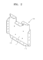
- FIG. 2 is a perspective view of an end plate 108 illustrated in FIG. 1 , according to an embodiment of the present invention.
- the end plate 108 includes a base plate 111 and a flange unit 112 bent from the base plate 111.
- the base plate 111 has a size that is sufficient to cover an outer surface of the battery units 101 illustrated in FIG. 1 .
- the base plate 111 has an almost square shape in FIG. 2 , the shape of the base plate 111 is not limited thereto.
- the flange unit 112 is bent from edges of the base plate 111 in a direction opposite to the direction in which the battery units 101 are arranged.
- the flange unit 112 may be variously bent according to a combination method with other elements.
- the flange unit 112 may have one bent portion from the base plate 111 without a cut at each of left, right, and bottom edges of the base plate 111, and may have a plurality of bent portions having different heights by cutting a portion of the base plate 111 at a top edge of the base plate 111.
- a plurality of combination holes 113 are formed in the flange unit 112.
- FIG. 3 is a magnified perspective view of a plurality of end plates 108 illustrated in FIG. 1 when the end plates 108 are connected, according to an embodiment of the present invention.
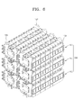
- FIG. 6 is a perspective view of a battery pack 300 in which a plurality of battery modules 100 illustrated in FIG. 1 are stacked, according to an embodiment of the present invention.
- the end plates 108 include and are substantially identical to upper and lower end plates 140 and 150 to be described later as well as the first and second end plates 106 and 107 illustrated in FIG. 1 .
- the battery pack 300 is an assembly of the battery modules 100 stacked in horizontal and vertical directions.
- the number of battery modules 100 may be determined in consideration of charge and discharge capacities required to design the battery pack 300.
- the battery modules 100 stacked in the horizontal and vertical directions are connected to each other.
- a pair of end plates 108 is separately mounted at outermost sides of every battery module 100.
- Neighboring battery modules 100 are combined by connecting to each other the end plates 108 mounted at the outermost sides of the battery modules 100.
- an upper battery module 120 and a lower battery module 130 arranged under the upper battery module 120 are combined as described below.
- An upper end plate 140 is disposed at an outermost side of the upper battery module 120.
- the upper end plate 140 includes an upper base plate 141 and an upper flange unit 142 bent from edges of the upper base plate 141.
- a lower end plate 150 is disposed at an outermost side of the lower battery module 130.
- the lower end plate 150 includes a lower base plate 151 and a lower flange unit 152 bent from edges of the lower base plate 151.
- the upper and lower end plates 140 and 150 are disposed at the same position in the vertical direction. At least a portion of the upper flange unit 142 bent from a bottom edge of the upper base plate 141 surface-contacts the lower flange unit 152 cut and bent from a top edge of the lower base plate 151.
- combination holes formed in the upper and lower flange units 142 and 152 are matched to each other and bolts 143 are inserted into the combination holes so as to be screwed into nuts 144.
- the upper and lower end plates 140 and 150 are combined with each other.
- the upper and lower battery modules 120 and 130 supported by the upper and lower end plates 140 and 150 may not be dislocated. In this manner, the battery modules 100 stacked in the horizontal and vertical directions are firmly fixed to each other.
- the combination method is not limited to any one combination method as long as the upper end plate 140 is combined with the lower end plate 150.
- a welding combination method may be used.
- reinforcement plates 401 for structurally reinforcing and supporting the battery modules 100 are further mounted on the battery modules 100.
- the reinforcement plates 401 include upper and lower reinforcement plates 402 and 403.
- FIG. 4 is a magnified perspective view of one of the end plates 108 illustrated in FIG. 3 when the end plate 108 is mounted, according to an embodiment of the present invention.
- FIG. 5 is a front view of the end plate 108 illustrated in FIG. 4 , according to an embodiment of the present invention.
- the end plate 108 includes a base plate 111, an upper flange unit 112a bent from a top edge of the base plate 111, and a lower flange unit 112b bent from a bottom edge of the base plate 111.
- the upper flange unit 112a forms a plurality of bent portions having different heights by cutting a portion of the base plate 111
- the lower flange unit 112b forms one bent portion from the base plate 111 without a cut.
- an upper reinforcement plate 402 is mounted on a top surface of a battery module 100 and a lower reinforcement plate 403 is mounted on a bottom surface of the battery module 100.
- the upper reinforcement plate 402 includes an upper base plate 404 disposed on the top surface of the battery module 100 along a length direction of the battery module 100, and upper bent portions 405 bent upward in a vertical direction from two side edges of the upper base plate 404.
- the lower reinforcement plate 403 includes a lower base plate 406 disposed on the bottom surface of the battery module 100 along the length direction of the battery module 100, and lower bent portions 407 bent downward in the vertical direction from two side edges of the lower base plate 406.
- An end of the upper base plate 404 is firmly fixed to the upper flange unit 112a by using fasteners such as a bolt 143 and a nut 144. Also, an end of the lower base plate 406 is combined with the lower flange unit 112b by using fasteners such as bolts 143 and nuts 144.
- the upper and lower reinforcement plates 402 and 403 prevent the battery module 100 from being deformed downward due to weights of a plurality of battery units 101.
- insulation plates 408 formed of an insulating material such as polymer resin in order to prevent shorts caused by a drop of the battery units 101 stacked in the vertical direction may be further mounted on a bottom surface of the upper base plate 404 facing the top surface of the battery module 100 and on a top surface of the lower base plate 406 facing the bottom surface of the battery module 100.
- the insulation plates 408 are attached on the upper and lower base plates 404 and 406 along length directions of the upper and lower base plates 404 and 406.
- the insulation plates 408 are not additional required.
- the insulation method between the battery units 101 and the upper and lower reinforcement plates 402 and 403 is not limited any one insulation method as long as the battery units 101 are insulated from the upper and lower reinforcement plates 402 and 403.
- the upper reinforcement plate 402 mounted on a bottom surface of the upper battery module 120 and the lower reinforcement plate 403 mounted on a top surface of the lower battery module 130 are combined with each other so as to form a sealed gas discharge hole 301.
- the gas discharge hole 301 may function as a gas passage.
- the battery pack 300 forms an assembly of the battery modules 100 stacked in the horizontal and vertical directions. Neighboring battery modules 100 may be firmly fixed by connecting to each other the first and second end plates 106 and 107 disposed at outermost sides of the battery modules 100.
- a battery pack may have advantages described below.
- the battery module may be firmly fixed to each other without an additional connection frame.
- the weight of a battery pack may be reduced.
- a plurality of battery units may be supported.
- a gas discharge passage may be formed between neighboring battery modules.
Landscapes
- Chemical & Material Sciences (AREA)
- Chemical Kinetics & Catalysis (AREA)
- Electrochemistry (AREA)
- General Chemical & Material Sciences (AREA)
- Battery Mounting, Suspending (AREA)
- Gas Exhaust Devices For Batteries (AREA)
- Secondary Cells (AREA)
Abstract
Description
- One or more embodiments of the present invention relate to a battery pack in which a plurality of stacked battery modules are connected to each other.
- In general, unlike primary batteries that are not chargeable, secondary batteries are chargeable and dischargeable. Secondary batteries are used as energy sources of mobile devices, electric vehicles, hybrid electric vehicles, electric bicycles, uninterruptible power supplies, etc.
- From among them, small devices such as the mobile devices use a small number of battery cells. On the other hand, medium or large devices such as the electric vehicles and hybrid electric vehicle require high power and large capacity and thus use a battery pack in which a plurality of battery cells are electrically connected to each other.
- Normally, a plurality of battery cells is connected in series or in parallel so as to be included in a battery unit. A plurality of battery units is connected to form a battery module. A plurality of battery modules are connected to form a battery pack in order to provide higher power and larger capacity.
- When a battery pack is assembled by using a plurality of battery modules, the battery modules need to be firmly connected to each other so as to achieve a stable structure of the battery pack.
- One or more embodiments of the present invention include a battery pack capable of easily connecting a plurality of stacked battery modules to each other.
- Additional aspects will be set forth in part in the description which follows and, in part, will be apparent from the description, or may be learned by practice of the presented embodiments.
- According to one or more embodiments of the present invention, a battery pack is provided comprising a plurality of battery modules. Each battery module comprises a plurality of battery units arranged along a first direction (Y), a first end plate and a second end plate. The plurality of battery units is arranged between the first and second end plate, wherein the first and second end plates are fixed to each other or are fixed to the plurality of battery units. The battery pack being characterized in that a first or second end plate of a first battery module is fixed to a first or second end plate of a second battery module being adjacent to the first battery module in order to connect adjacent battery modules of the battery pack.
- The first and second end plates of the battery pack of the invention can be fixed to each other by a first guide plate arranged along said first direction (Y) on a first side surface of the plurality of battery units and coupled to the first and second end plate, and by a second guide plate arranged along said first direction (Y) on a second side surface of the plurality of battery units being opposite to said first side surface and coupled to the first and second end plates.
- The first and second end plates of the battery pack of the invention can comprise a base plate and at least one flange unit extending from the base plate to combine different end plates with each other and/or to fix the guide plates thereto.
- In the battery pack of the invention, the at least one flange unit can extend from side surfaces of the base plate in a direction away from the plurality of battery units.
- A battery module of the battery pack of the invention may further comprise at least one of a first reinforcement plate mounted on a third side surface of the plurality of battery units, extending in the first direction (Y) and coupled to the first and second end plates; and a second reinforcement plate mounted on a fourth side surface of the plurality of battery units opposite the third side surface, extending in the first direction (Y) and coupled to the first and second end plates.
- In the battery pack of the invention, said first reinforcement plate may comprise a first base plate on the third side of the plurality of battery units and first bent portions extending from sides of the first base plate away from the plurality of battery units, and said second reinforcement plate may comprise a second base plate on the fourth side of the plurality of battery units and second bent portions extending from sides of the second base plate away from the plurality of battery units.
- In the battery pack of the invention, said first reinforcement plate of a first battery module may be combined to said second reinforcement plate of a second, adjacent battery module such that a gas discharge path is formed.
- An insulation plate can be mounted on a surface of the first and/or second base plate facing the battery module to which the respective reinforcement plate is mounted.
- In the battery pack of the invention, the at least one flange unit may comprise a first flange unit extending from a first side of the base plate, a second flange unit extending from a second side of the base plate, the second side being opposite to the first side, a third flange unit extending from a third side of the base plate, and a fourth flange unit extending from a fourth side of the base plate, the fourth side being opposite to the third side.
- The first guide plate may be attached to the first flange unit and the second guide plate may be attached to the second flange unit.
- Furthermore, the first reinforcement plate may be attached to the third flange unit and the second reinforcement plate may be attached to the fourth flange unit.
- The third flange unit can comprises a reduced height part adapted to receive said first reinforcement plate of the respective battery module and a second reinforcement plate of a neighboring battery module.
- In the battery pack of the invention, the at least one flange unit can comprise combination holes to combine different end plates with each other.
- Connecting elements may be used to combine the combination holes of different end plates. Connecting elements being nuts and bolts can be used to combine the combination holes of different end plates.
- In the battery pack of the invention, the first and second guide plates may comprise heat-radiating holes.
- These and/or other aspects will become apparent and more readily appreciated from the following description of the embodiments, taken in conjunction with the accompanying drawings of which:
-
FIG. 1 is a perspective view of a battery module, according to an embodiment of the present invention; -
FIG. 2 is a perspective view of an end plate of the battery module illustrated inFIG. 1 , according to an embodiment of the present invention; -
FIG. 3 is a magnified perspective view of a plurality of end plates illustrated inFIG. 1 when the end plates are connected, according to an embodiment of the present invention; -
FIG. 4 is a magnified perspective view of one of the end plates illustrated inFIG. 3 when the end plate is mounted, according to an embodiment of the present invention; -
FIG. 5 is a front view of the end plate illustrated inFIG. 4 , according to an embodiment of the present invention; and -
FIG. 6 is a perspective view of a battery pack in which a plurality of battery modules illustrated inFIG. 1 are stacked, according to an embodiment of the present invention. - Reference will now be made in detail to embodiments, examples of which are illustrated in the accompanying drawings, wherein like reference numerals refer to the like elements throughout. In this regard, the present embodiments may have different forms and should not be construed as being limited to the descriptions set forth herein. Accordingly, the embodiments are merely described below, by referring to the figures, to explain aspects of the present description.
-
FIG. 1 is a perspective view of abattery module 100, according to an embodiment of the present invention. - Referring to
FIG. 1 , thebattery module 100 includes a plurality ofbattery units 101. Thebattery units 101 are sequentially arranged along a horizontal direction (Y direction). Alternatively, thebattery units 101 may be sequentially arranged along a vertical direction (Z direction). The structure of thebattery units 101 is not limited to any one structure as long as thebattery units 101 are stacked in one direction. - Although not shown in
FIG. 1 , a plurality of battery cells is stacked in everybattery unit 101 and is accommodated in acase 102. - A secondary battery such as a general lithium secondary battery may be used as a battery cell. For example, the battery cell may be a cylindrical secondary battery, an angular secondary battery, or a polymer secondary battery and is not limited to any one secondary battery. The battery cells are electrically connected by using positive and negative electrode tabs that are respectively and electrically connected to positive and
negative terminals case 102. For example, the battery cells may be connected in parallel, in series, or in parallel and series and the connection method of the battery cells is not limited to any one connection method. - The
battery units 101 are arranged so that polarities of neighboringbattery units 101 are opposite to each other. Thepositive terminal 103 of onebattery unit 101 is connected to thenegative terminal 104 of a neighboringbattery unit 101 by using abus bar 105. - As such, the
battery units 101 are sequentially connected to form onebattery module 100. The number ofbattery units 101 may be determined in consideration of charge and discharge capacities required to design thebattery module 100. - A pair of
end plates 108 are separately mounted at outermost sides of thebattery module 100. Theend plates 108 include afirst end plate 106 mounted at one end of thebattery module 100 and asecond end plate 107 mounted at the other end of thebattery module 100. - One surface of the
first end plate 106 and one surface of thesecond end plate 107 separately contact outer surfaces of thebattery units 101 arranged at the outermost sides of thebattery module 100. - The first and
second end plates guide plates 109. Theguide plates 109 extend along side walls of thebattery units 101. Each of theguide plates 109 is a strip-type plate of which one end is screw-combined with thefirst end plate 106 and the other end is screw-combined with thesecond end plate 107. As such, thebattery units 101 may not be dislocated from their sequentially arranged positions in the horizontal direction. -
Heat radiating holes 110 are formed in theguide plates 109. Theheat radiating holes 110 are arranged at uniform intervals along a length direction of theguide plates 109. Theheat radiating holes 110 are formed to rapidly radiate to the outside heat generated from thebattery units 101 during operation. -
FIG. 2 is a perspective view of anend plate 108 illustrated inFIG. 1 , according to an embodiment of the present invention. - Referring to
FIG. 2 , theend plate 108 includes abase plate 111 and aflange unit 112 bent from thebase plate 111. Thebase plate 111 has a size that is sufficient to cover an outer surface of thebattery units 101 illustrated inFIG. 1 . Although thebase plate 111 has an almost square shape inFIG. 2 , the shape of thebase plate 111 is not limited thereto. - The
flange unit 112 is bent from edges of thebase plate 111 in a direction opposite to the direction in which thebattery units 101 are arranged. Theflange unit 112 may be variously bent according to a combination method with other elements. For example, theflange unit 112 may have one bent portion from thebase plate 111 without a cut at each of left, right, and bottom edges of thebase plate 111, and may have a plurality of bent portions having different heights by cutting a portion of thebase plate 111 at a top edge of thebase plate 111. - Meanwhile, a plurality of combination holes 113 are formed in the
flange unit 112. -
FIG. 3 is a magnified perspective view of a plurality ofend plates 108 illustrated inFIG. 1 when theend plates 108 are connected, according to an embodiment of the present invention.FIG. 6 is a perspective view of abattery pack 300 in which a plurality ofbattery modules 100 illustrated inFIG. 1 are stacked, according to an embodiment of the present invention. - In
FIG. 3 , theend plates 108 include and are substantially identical to upper andlower end plates 140 and 150 to be described later as well as the first andsecond end plates FIG. 1 . - Referring to
FIGS. 3 and6 , thebattery pack 300 is an assembly of thebattery modules 100 stacked in horizontal and vertical directions. The number ofbattery modules 100 may be determined in consideration of charge and discharge capacities required to design thebattery pack 300. - In this case, the
battery modules 100 stacked in the horizontal and vertical directions are connected to each other. As described above in relation toFIG. 1 , a pair ofend plates 108 is separately mounted at outermost sides of everybattery module 100. Neighboringbattery modules 100 are combined by connecting to each other theend plates 108 mounted at the outermost sides of thebattery modules 100. - For example, an
upper battery module 120 and alower battery module 130 arranged under theupper battery module 120 are combined as described below. - An upper end plate 140 is disposed at an outermost side of the
upper battery module 120. The upper end plate 140 includes an upper base plate 141 and an upper flange unit 142 bent from edges of the upper base plate 141. Alower end plate 150 is disposed at an outermost side of thelower battery module 130. Thelower end plate 150 includes alower base plate 151 and alower flange unit 152 bent from edges of thelower base plate 151. - The upper and
lower end plates 140 and 150 are disposed at the same position in the vertical direction. At least a portion of the upper flange unit 142 bent from a bottom edge of the upper base plate 141 surface-contacts thelower flange unit 152 cut and bent from a top edge of thelower base plate 151. - In this case, combination holes formed in the upper and
lower flange units 142 and 152 are matched to each other andbolts 143 are inserted into the combination holes so as to be screwed into nuts 144. - As such, the upper and
lower end plates 140 and 150 are combined with each other. The upper andlower battery modules lower end plates 140 and 150 may not be dislocated. In this manner, thebattery modules 100 stacked in the horizontal and vertical directions are firmly fixed to each other. - Meanwhile, although a combination method using fasteners such as the
bolts 143 and the nuts144 is described above, the combination method is not limited to any one combination method as long as the upper end plate 140 is combined with thelower end plate 150. For example, a welding combination method may be used. - Furthermore,
reinforcement plates 401 for structurally reinforcing and supporting thebattery modules 100 are further mounted on thebattery modules 100. Thereinforcement plates 401 include upper andlower reinforcement plates -
FIG. 4 is a magnified perspective view of one of theend plates 108 illustrated inFIG. 3 when theend plate 108 is mounted, according to an embodiment of the present invention.FIG. 5 is a front view of theend plate 108 illustrated inFIG. 4 , according to an embodiment of the present invention. - Referring to
FIGS. 4 and5 , theend plate 108 includes abase plate 111, anupper flange unit 112a bent from a top edge of thebase plate 111, and alower flange unit 112b bent from a bottom edge of thebase plate 111. Theupper flange unit 112a forms a plurality of bent portions having different heights by cutting a portion of thebase plate 111, and thelower flange unit 112b forms one bent portion from thebase plate 111 without a cut. - In this case, an
upper reinforcement plate 402 is mounted on a top surface of abattery module 100 and alower reinforcement plate 403 is mounted on a bottom surface of thebattery module 100. Theupper reinforcement plate 402 includes anupper base plate 404 disposed on the top surface of thebattery module 100 along a length direction of thebattery module 100, and upperbent portions 405 bent upward in a vertical direction from two side edges of theupper base plate 404. Thelower reinforcement plate 403 includes alower base plate 406 disposed on the bottom surface of thebattery module 100 along the length direction of thebattery module 100, and lowerbent portions 407 bent downward in the vertical direction from two side edges of thelower base plate 406. - An end of the
upper base plate 404 is firmly fixed to theupper flange unit 112a by using fasteners such as abolt 143 and anut 144. Also, an end of thelower base plate 406 is combined with thelower flange unit 112b by using fasteners such asbolts 143 and nuts 144. - As such, the upper and
lower reinforcement plates battery module 100 from being deformed downward due to weights of a plurality ofbattery units 101. - Furthermore,
insulation plates 408 formed of an insulating material such as polymer resin in order to prevent shorts caused by a drop of thebattery units 101 stacked in the vertical direction may be further mounted on a bottom surface of theupper base plate 404 facing the top surface of thebattery module 100 and on a top surface of thelower base plate 406 facing the bottom surface of thebattery module 100. Theinsulation plates 408 are attached on the upper andlower base plates lower base plates - Alternatively, if the upper and
lower reinforcement plates insulation plates 408 are not additional required. - The insulation method between the
battery units 101 and the upper andlower reinforcement plates battery units 101 are insulated from the upper andlower reinforcement plates - Referring back to
FIGS. 3 and6 , theupper reinforcement plate 402 mounted on a bottom surface of theupper battery module 120 and thelower reinforcement plate 403 mounted on a top surface of thelower battery module 130 are combined with each other so as to form a sealedgas discharge hole 301. As such, when a gas is generated from inside thebattery units 101 due to a damage of thelower battery module 130, thegas discharge hole 301 may function as a gas passage. - As such, as illustrated in
FIG. 6 , thebattery pack 300 forms an assembly of thebattery modules 100 stacked in the horizontal and vertical directions. Neighboringbattery modules 100 may be firmly fixed by connecting to each other the first andsecond end plates battery modules 100. - As described above, according to the one or more of the above embodiments of the present invention, a battery pack may have advantages described below.
- First, as stacked battery modules are connected to each other by using end plates, the battery module may be firmly fixed to each other without an additional connection frame.
- Second, as the additional connection frame is not required, the weight of a battery pack may be reduced.
- Third, the structure of the stacked battery modules is simplified.
- Fourth, as the stacked battery modules have the same connection structure, manufacturing costs may be reduced.
- Fifth, as reinforcement plates are mounted between the stacked battery modules, a plurality of battery units may be supported.
- Sixth, as the reinforcement plates are mounted, a gas discharge passage may be formed between neighboring battery modules.
- It should be understood that the exemplary embodiments described therein should be considered in a descriptive sense. Descriptions of features or aspects within each embodiment should typically be considered as available for other similar features or aspects in other embodiments.
Claims (15)
- A battery pack (300) comprising a plurality of battery modules (100), each battery module (100) comprising:a plurality of battery units (101) arranged along a first direction (Y),a first end plate (108) and a second end plate (107), wherein the plurality of battery units (101) is arranged between the first and second end plate (108, 107),
wherein the first and second end plates (108, 107) are fixed to each other or are fixed to the plurality of battery units (101),
characterized in thata first or second end plate (108, 107) of a first battery module is fixed to a first or second end plate of a second, adjacent battery module (108, 107) to connect adjacent battery modules (100) of the battery pack (300). - The battery pack (300) of claim 1, wherein the first and second end plates (108, 107) are fixed to each other by:a first guide plate (109) arranged along said first direction (Y) on a first side surface of the plurality of battery units (101) and coupled to the first and second end plate (108, 107),a second guide plate (109) arranged along said first direction (Y) on a second side surface of the plurality of battery units (101) being opposite to said first side surface and coupled to the first and second end plates (108, 107).
- The battery pack (300) of claim 1 or 2, wherein each of the first and second end plates (108, 107) comprises a base plate (111) and at least one flange unit (112) extending from the base plate (111) to combine different end plates (108, 107) with each other and/or to fix the guide plates (109) thereto.
- The battery pack (300) of claim 3, wherein the at least one flange unit (112) extends from side surfaces of the base plate (111) in a direction away from the plurality of battery units (101).
- The battery pack (300) of any of the previous claims, wherein a battery module (100) further comprises at least one of:a first reinforcement plate (402) mounted on a third side surface of the plurality of battery units (101), extending in the first direction (Y) and coupled to the first and second end plates (108, 107); anda second reinforcement plate (403) mounted on a fourth side surface of the plurality of battery units (101) opposite the third side surface, extending in the first direction (Y) and coupled to the first and second end plates (108, 107).
- The battery pack (300) of claim 5, wherein
the first reinforcement plate (402) comprises a first base plate (404) on the third side of the plurality of battery units (101) and first bent portions (405) extending from sides of the first base plate (404) away from the plurality of battery units (101), and
the second reinforcement plate (403) comprises a second base plate (406) on the fourth side of the plurality of battery units (101) and second bent portions (407) extending from sides of the second base plate (406) away from the plurality of battery units (101). - The battery pack (300) of any of claim 6, wherein a first reinforcement plate (402) of a first battery module (100) combined to a second reinforcement plate (403) of a second, adjacent battery module (100) forms a gas discharge path (301).
- The battery pack (300) of any of claim 6 or 7, wherein an insulation plate (408) is mounted on a surface of the first and/or second base plate (404, 406) facing the battery module (100) to which the respective reinforcement plate (403, 403) is mounted.
- The battery pack (300) of any of claims 3 to 8, wherein the at least one flange unit (112) comprises:a first flange unit (112) extending from a first side of the base plate (111),a second flange unit (112) extending from a second side of the base plate (111),the second side being opposite to the first side,a third flange unit (112a) extending from a third side of the base plate (111), anda fourth flange unit (112b) extending from a fourth side of the base plate (111), the fourth side being opposite to the third side.
- The battery pack (300) of claim 9, wherein the first guide plate (109) attaches to the first flange unit (112) and the second guide plate (109) attaches to the second flange unit (112).
- The battery pack (300) of claim 9 or 10, wherein the first reinforcement plate (402) is attached to the third flange unit (112a) and the second reinforcement plate (403) is attached to the fourth flange unit (112b).
- The battery pack of claim 11, wherein the third flange unit (112a) comprises a reduced height part adapted to receive said first reinforcement plate (402) of the respective battery module (100) and a second reinforcement plate of a neighboring battery module (100).
- The battery pack (300) of one of any of claims 3 to 12, wherein the at least one flange unit (112) comprises combination holes (113) to combine different end plates (108, 107) with each other.
- The battery pack (300) of claim 13, wherein connecting elements (143, 144) are used to combine the combination holes (113) of different end plates (108, 107),.and/or wherein connecting elements being nuts (144) and bolts (143) are used to combine the combination holes (113) of different end plates (108, 107).
- The battery pack (300) of any of the previous claims, wherein the first and second guide plates (109) comprise heat-radiating holes (110).
Applications Claiming Priority (2)
| Application Number | Priority Date | Filing Date | Title |
|---|---|---|---|
| US25855809P | 2009-11-05 | 2009-11-05 | |
| US12/814,372 US8734978B2 (en) | 2009-11-05 | 2010-06-11 | Battery pack |
Publications (2)
| Publication Number | Publication Date |
|---|---|
| EP2328201A1 true EP2328201A1 (en) | 2011-06-01 |
| EP2328201B1 EP2328201B1 (en) | 2012-03-21 |
Family
ID=43618860
Family Applications (1)
| Application Number | Title | Priority Date | Filing Date |
|---|---|---|---|
| EP10189920A Active EP2328201B1 (en) | 2009-11-05 | 2010-11-04 | Battery Pack |
Country Status (6)
| Country | Link |
|---|---|
| US (2) | US8734978B2 (en) |
| EP (1) | EP2328201B1 (en) |
| JP (1) | JP5271334B2 (en) |
| KR (1) | KR101217072B1 (en) |
| CN (1) | CN102054950B (en) |
| AT (1) | ATE550795T1 (en) |
Cited By (4)
| Publication number | Priority date | Publication date | Assignee | Title |
|---|---|---|---|---|
| US8623535B2 (en) | 2011-02-15 | 2014-01-07 | Samsung Sdi Co., Ltd. | Battery module |
| EP3223339A4 (en) * | 2015-03-16 | 2018-05-23 | LG Chem, Ltd. | Battery compression inhibitor and battery module comprising same |
| WO2020229200A1 (en) * | 2019-05-10 | 2020-11-19 | Monbat New Power GmbH | Modular system for the assembly of a device for storing electrical energy |
| EP3799150A4 (en) * | 2018-12-27 | 2021-10-06 | Contemporary Amperex Technology Co., Limited | Battery box |
Families Citing this family (21)
| Publication number | Priority date | Publication date | Assignee | Title |
|---|---|---|---|---|
| ATE557432T1 (en) * | 2009-11-19 | 2012-05-15 | Sb Limotive Co Ltd | BATTERY PACK |
| KR101117686B1 (en) * | 2009-12-28 | 2012-02-29 | 에스비리모티브 주식회사 | Battery module and battery pack having the same |
| KR101312141B1 (en) * | 2012-04-25 | 2013-10-14 | 주식회사 성화 | Dc power supply backup device using litium series end cell batteries |
| CN102903980A (en) * | 2012-09-27 | 2013-01-30 | 山东润峰电子科技有限公司 | Combined battery |
| JP6114041B2 (en) * | 2013-01-21 | 2017-04-12 | 住友重機械工業株式会社 | Storage module and work machine equipped with storage module |
| WO2016002178A1 (en) * | 2014-07-02 | 2016-01-07 | 三洋電機株式会社 | Power source device |
| US10868287B2 (en) * | 2015-07-22 | 2020-12-15 | Ford Global Technologies, Llc | Battery pack endplate |
| KR101805652B1 (en) * | 2015-08-28 | 2017-12-06 | 삼성에스디아이 주식회사 | Rechargeable battery pack |
| KR101805650B1 (en) | 2015-08-28 | 2017-12-06 | 삼성에스디아이 주식회사 | Rechargeable battery pack |
| CN106531912B (en) * | 2015-09-15 | 2022-07-19 | 北京普莱德新能源电池科技有限公司 | Square battery module |
| KR102507879B1 (en) * | 2015-11-16 | 2023-03-07 | 삼성에스디아이 주식회사 | Rechargeable battery module |
| JP6661378B2 (en) * | 2016-01-13 | 2020-03-11 | 本田技研工業株式会社 | Fuel cell stack |
| CN113690520A (en) * | 2016-11-16 | 2021-11-23 | 奥动新能源汽车科技有限公司 | Vehicle-mounted power battery box |
| JP6545212B2 (en) | 2017-03-17 | 2019-07-17 | 本田技研工業株式会社 | Battery pack |
| KR102319537B1 (en) * | 2017-12-20 | 2021-10-29 | 주식회사 엘지에너지솔루션 | Battery module, battery pack and vehicle comprising the same |
| TWI662734B (en) * | 2018-01-18 | 2019-06-11 | 車王電子股份有限公司 | Battery holder and its side frame |
| CN110085781B (en) * | 2018-01-25 | 2022-04-05 | 车王电子股份有限公司 | Battery fixing frame and side frame thereof |
| CN108777268A (en) * | 2018-04-19 | 2018-11-09 | 芜湖天量电池系统有限公司 | A kind of novel power battery pack arrangement and its packaging technology |
| CN111384325B (en) | 2018-12-29 | 2021-02-12 | 宁德时代新能源科技股份有限公司 | Battery pack |
| CN209401683U (en) * | 2018-12-29 | 2019-09-17 | 宁德时代新能源科技股份有限公司 | Secondary cell and battery modules |
| US12002975B2 (en) * | 2020-12-01 | 2024-06-04 | Caterpillar Inc. | Structural battery module and battery pack |
Citations (3)
| Publication number | Priority date | Publication date | Assignee | Title |
|---|---|---|---|---|
| US20050084748A1 (en) * | 2001-11-20 | 2005-04-21 | Miller Russell L. | Battery rack and system |
| WO2008035873A1 (en) * | 2006-09-18 | 2008-03-27 | Lg Chem, Ltd. | Battery module interface |
| US20090263705A1 (en) * | 2008-04-18 | 2009-10-22 | Cobasys, Llc | Isolation tray for a battery system |
Family Cites Families (28)
| Publication number | Priority date | Publication date | Assignee | Title |
|---|---|---|---|---|
| JPS603519Y2 (en) * | 1980-03-18 | 1985-01-31 | ウシオ電機株式会社 | flash lamp power supply |
| JPH08303682A (en) | 1995-05-10 | 1996-11-22 | Kubota Corp | Heat insulating box |
| JP3271494B2 (en) * | 1995-10-24 | 2002-04-02 | 松下電器産業株式会社 | Stacked sealed alkaline storage battery |
| US5981101A (en) * | 1997-06-02 | 1999-11-09 | Gnb Technologies, Inc. | Modular cell tray assembly for sealed lead-acid cells |
| JP4088359B2 (en) | 1997-10-20 | 2008-05-21 | 松下電器産業株式会社 | Collective sealed secondary battery |
| US6326103B1 (en) * | 1998-03-25 | 2001-12-04 | Matsushita Electric Industrial Co., Ltd. | Sealed storage battery and modular system therefor |
| JP4837155B2 (en) * | 1998-11-27 | 2011-12-14 | パナソニック株式会社 | Storage battery |
| JP4965012B2 (en) * | 1999-12-15 | 2012-07-04 | トヨタ自動車株式会社 | Battery pack for vehicles |
| KR100353998B1 (en) * | 1999-12-30 | 2002-09-27 | 현대자동차주식회사 | Battery module structure for electric vehicles |
| JP2003157817A (en) | 2001-11-22 | 2003-05-30 | Japan Storage Battery Co Ltd | Unit case and storage battery housing box |
| JP4242665B2 (en) | 2002-05-13 | 2009-03-25 | パナソニック株式会社 | Battery pack cooling device and secondary battery |
| JP3667724B2 (en) | 2002-09-12 | 2005-07-06 | 古河電池株式会社 | Battery housing and cubicle type storage battery panel using the same |
| US7323271B2 (en) * | 2003-08-27 | 2008-01-29 | Kim Manufacturing Company | Front access battery tray apparatus and system |
| US8557429B2 (en) * | 2005-02-18 | 2013-10-15 | Toyota Jidosha Kabushiki Kaisha | Battery pack having battery modules held by holding spacers |
| JP2006318703A (en) * | 2005-05-11 | 2006-11-24 | Kojima Press Co Ltd | Battery pack |
| JP2007048750A (en) * | 2005-08-10 | 2007-02-22 | Samsung Sdi Co Ltd | Battery module |
| KR101256058B1 (en) * | 2005-09-05 | 2013-04-22 | 삼성에스디아이 주식회사 | Secondary battery module |
| KR100696638B1 (en) * | 2005-09-05 | 2007-03-19 | 삼성에스디아이 주식회사 | Secondary battery module |
| KR100709261B1 (en) * | 2005-11-15 | 2007-04-19 | 삼성에스디아이 주식회사 | Secondary battery module |
| CN2879430Y (en) * | 2005-12-30 | 2007-03-14 | 春兰(集团)公司 | Metal shell battery module |
| KR100805152B1 (en) | 2006-04-10 | 2008-02-21 | 삼성에스디아이 주식회사 | Battery module |
| KR100892046B1 (en) * | 2006-09-18 | 2009-04-07 | 주식회사 엘지화학 | Battery Module, and Middle or Large-sized Battery Pack Containing The Same |
| KR101201813B1 (en) | 2006-10-17 | 2012-11-15 | 삼성에스디아이 주식회사 | Battery module |
| JP5096038B2 (en) | 2007-05-09 | 2012-12-12 | トヨタ自動車株式会社 | Battery pack structure |
| JP5334420B2 (en) * | 2008-01-16 | 2013-11-06 | 三洋電機株式会社 | Battery system |
| JP2009187813A (en) * | 2008-02-07 | 2009-08-20 | Toyota Motor Corp | Power supply device |
| US8440343B2 (en) * | 2008-04-25 | 2013-05-14 | Honda Motor Co., Ltd. | Electricity storage system and metal battery case manufacturing method |
| KR101182426B1 (en) * | 2009-12-04 | 2012-09-12 | 에스비리모티브 주식회사 | Battery module and battery pack having the same |
-
2010
- 2010-06-11 US US12/814,372 patent/US8734978B2/en active Active
- 2010-08-11 KR KR1020100077493A patent/KR101217072B1/en active IP Right Grant
- 2010-10-29 JP JP2010243590A patent/JP5271334B2/en active Active
- 2010-11-04 EP EP10189920A patent/EP2328201B1/en active Active
- 2010-11-04 CN CN201010535349.7A patent/CN102054950B/en active Active
- 2010-11-04 AT AT10189920T patent/ATE550795T1/en active
-
2014
- 2014-04-15 US US14/253,774 patent/US20140227569A1/en not_active Abandoned
Patent Citations (3)
| Publication number | Priority date | Publication date | Assignee | Title |
|---|---|---|---|---|
| US20050084748A1 (en) * | 2001-11-20 | 2005-04-21 | Miller Russell L. | Battery rack and system |
| WO2008035873A1 (en) * | 2006-09-18 | 2008-03-27 | Lg Chem, Ltd. | Battery module interface |
| US20090263705A1 (en) * | 2008-04-18 | 2009-10-22 | Cobasys, Llc | Isolation tray for a battery system |
Cited By (7)
| Publication number | Priority date | Publication date | Assignee | Title |
|---|---|---|---|---|
| US8623535B2 (en) | 2011-02-15 | 2014-01-07 | Samsung Sdi Co., Ltd. | Battery module |
| EP2490277B1 (en) * | 2011-02-15 | 2018-08-22 | Samsung SDI Co., Ltd. | Battery Module |
| EP3223339A4 (en) * | 2015-03-16 | 2018-05-23 | LG Chem, Ltd. | Battery compression inhibitor and battery module comprising same |
| US11271266B2 (en) | 2015-03-16 | 2022-03-08 | Lg Energy Solution, Ltd. | Battery compression inhibitor and battery module comprising same |
| EP3799150A4 (en) * | 2018-12-27 | 2021-10-06 | Contemporary Amperex Technology Co., Limited | Battery box |
| US11949114B2 (en) | 2018-12-27 | 2024-04-02 | Contemporary Amperex Technology Co., Limited | Battery box |
| WO2020229200A1 (en) * | 2019-05-10 | 2020-11-19 | Monbat New Power GmbH | Modular system for the assembly of a device for storing electrical energy |
Also Published As
| Publication number | Publication date |
|---|---|
| US20110104552A1 (en) | 2011-05-05 |
| KR101217072B1 (en) | 2012-12-31 |
| JP5271334B2 (en) | 2013-08-21 |
| JP2011100727A (en) | 2011-05-19 |
| CN102054950A (en) | 2011-05-11 |
| US20140227569A1 (en) | 2014-08-14 |
| ATE550795T1 (en) | 2012-04-15 |
| EP2328201B1 (en) | 2012-03-21 |
| US8734978B2 (en) | 2014-05-27 |
| CN102054950B (en) | 2015-02-18 |
| KR20110049655A (en) | 2011-05-12 |
Similar Documents
| Publication | Publication Date | Title |
|---|---|---|
| EP2328201B1 (en) | Battery Pack | |
| US8859131B2 (en) | Battery module and battery pack including the same | |
| US10062879B2 (en) | Battery module assembly of improved reliability and battery pack employed with the same | |
| US9196882B2 (en) | Battery pack of compact structure | |
| US9023508B2 (en) | Bus bar assembly of novel structure | |
| US9083029B2 (en) | Battery pack | |
| US20240266680A1 (en) | Battery pack including connection plate | |
| CN109891626A (en) | Battery pack | |
| KR101302357B1 (en) | Battery Pack Having Novel Structure | |
| JP7460777B2 (en) | Battery module, battery pack and vehicle including the same, and method for manufacturing the battery pack | |
| KR20180107569A (en) | Battery pack | |
| EP4050722A1 (en) | Battery pack having connection plates, electronic device, and vehicle | |
| US12015172B2 (en) | Battery pack including connection plate, electronic device and vehicle | |
| KR20240058044A (en) | Battery pack and energy storage system comprising the same |
Legal Events
| Date | Code | Title | Description |
|---|---|---|---|
| PUAI | Public reference made under article 153(3) epc to a published international application that has entered the european phase |
Free format text: ORIGINAL CODE: 0009012 |
|
| 17P | Request for examination filed |
Effective date: 20101104 |
|
| AK | Designated contracting states |
Kind code of ref document: A1 Designated state(s): AL AT BE BG CH CY CZ DE DK EE ES FI FR GB GR HR HU IE IS IT LI LT LU LV MC MK MT NL NO PL PT RO RS SE SI SK SM TR |
|
| AX | Request for extension of the european patent |
Extension state: BA ME |
|
| GRAP | Despatch of communication of intention to grant a patent |
Free format text: ORIGINAL CODE: EPIDOSNIGR1 |
|
| RIC1 | Information provided on ipc code assigned before grant |
Ipc: H01M 2/10 20060101AFI20110930BHEP |
|
| GRAS | Grant fee paid |
Free format text: ORIGINAL CODE: EPIDOSNIGR3 |
|
| GRAA | (expected) grant |
Free format text: ORIGINAL CODE: 0009210 |
|
| AK | Designated contracting states |
Kind code of ref document: B1 Designated state(s): AL AT BE BG CH CY CZ DE DK EE ES FI FR GB GR HR HU IE IS IT LI LT LU LV MC MK MT NL NO PL PT RO RS SE SI SK SM TR |
|
| REG | Reference to a national code |
Ref country code: GB Ref legal event code: FG4D |
|
| REG | Reference to a national code |
Ref country code: CH Ref legal event code: EP |
|
| REG | Reference to a national code |
Ref country code: IE Ref legal event code: FG4D |
|
| REG | Reference to a national code |
Ref country code: AT Ref legal event code: REF Ref document number: 550795 Country of ref document: AT Kind code of ref document: T Effective date: 20120415 |
|
| REG | Reference to a national code |
Ref country code: DE Ref legal event code: R096 Ref document number: 602010001112 Country of ref document: DE Effective date: 20120516 |
|
| REG | Reference to a national code |
Ref country code: NL Ref legal event code: VDEP Effective date: 20120321 |
|
| PG25 | Lapsed in a contracting state [announced via postgrant information from national office to epo] |
Ref country code: HR Free format text: LAPSE BECAUSE OF FAILURE TO SUBMIT A TRANSLATION OF THE DESCRIPTION OR TO PAY THE FEE WITHIN THE PRESCRIBED TIME-LIMIT Effective date: 20120321 Ref country code: LT Free format text: LAPSE BECAUSE OF FAILURE TO SUBMIT A TRANSLATION OF THE DESCRIPTION OR TO PAY THE FEE WITHIN THE PRESCRIBED TIME-LIMIT Effective date: 20120321 Ref country code: NO Free format text: LAPSE BECAUSE OF FAILURE TO SUBMIT A TRANSLATION OF THE DESCRIPTION OR TO PAY THE FEE WITHIN THE PRESCRIBED TIME-LIMIT Effective date: 20120621 |
|
| LTIE | Lt: invalidation of european patent or patent extension |
Effective date: 20120321 |
|
| PG25 | Lapsed in a contracting state [announced via postgrant information from national office to epo] |
Ref country code: GR Free format text: LAPSE BECAUSE OF FAILURE TO SUBMIT A TRANSLATION OF THE DESCRIPTION OR TO PAY THE FEE WITHIN THE PRESCRIBED TIME-LIMIT Effective date: 20120622 Ref country code: FI Free format text: LAPSE BECAUSE OF FAILURE TO SUBMIT A TRANSLATION OF THE DESCRIPTION OR TO PAY THE FEE WITHIN THE PRESCRIBED TIME-LIMIT Effective date: 20120321 Ref country code: LV Free format text: LAPSE BECAUSE OF FAILURE TO SUBMIT A TRANSLATION OF THE DESCRIPTION OR TO PAY THE FEE WITHIN THE PRESCRIBED TIME-LIMIT Effective date: 20120321 Ref country code: RS Free format text: LAPSE BECAUSE OF FAILURE TO SUBMIT A TRANSLATION OF THE DESCRIPTION OR TO PAY THE FEE WITHIN THE PRESCRIBED TIME-LIMIT Effective date: 20120321 |
|
| REG | Reference to a national code |
Ref country code: AT Ref legal event code: MK05 Ref document number: 550795 Country of ref document: AT Kind code of ref document: T Effective date: 20120321 |
|
| PG25 | Lapsed in a contracting state [announced via postgrant information from national office to epo] |
Ref country code: CY Free format text: LAPSE BECAUSE OF FAILURE TO SUBMIT A TRANSLATION OF THE DESCRIPTION OR TO PAY THE FEE WITHIN THE PRESCRIBED TIME-LIMIT Effective date: 20120321 |
|
| PG25 | Lapsed in a contracting state [announced via postgrant information from national office to epo] |
Ref country code: RO Free format text: LAPSE BECAUSE OF FAILURE TO SUBMIT A TRANSLATION OF THE DESCRIPTION OR TO PAY THE FEE WITHIN THE PRESCRIBED TIME-LIMIT Effective date: 20120321 Ref country code: IS Free format text: LAPSE BECAUSE OF FAILURE TO SUBMIT A TRANSLATION OF THE DESCRIPTION OR TO PAY THE FEE WITHIN THE PRESCRIBED TIME-LIMIT Effective date: 20120721 Ref country code: EE Free format text: LAPSE BECAUSE OF FAILURE TO SUBMIT A TRANSLATION OF THE DESCRIPTION OR TO PAY THE FEE WITHIN THE PRESCRIBED TIME-LIMIT Effective date: 20120321 Ref country code: SI Free format text: LAPSE BECAUSE OF FAILURE TO SUBMIT A TRANSLATION OF THE DESCRIPTION OR TO PAY THE FEE WITHIN THE PRESCRIBED TIME-LIMIT Effective date: 20120321 Ref country code: BE Free format text: LAPSE BECAUSE OF FAILURE TO SUBMIT A TRANSLATION OF THE DESCRIPTION OR TO PAY THE FEE WITHIN THE PRESCRIBED TIME-LIMIT Effective date: 20120321 Ref country code: SE Free format text: LAPSE BECAUSE OF FAILURE TO SUBMIT A TRANSLATION OF THE DESCRIPTION OR TO PAY THE FEE WITHIN THE PRESCRIBED TIME-LIMIT Effective date: 20120321 Ref country code: PL Free format text: LAPSE BECAUSE OF FAILURE TO SUBMIT A TRANSLATION OF THE DESCRIPTION OR TO PAY THE FEE WITHIN THE PRESCRIBED TIME-LIMIT Effective date: 20120321 Ref country code: CZ Free format text: LAPSE BECAUSE OF FAILURE TO SUBMIT A TRANSLATION OF THE DESCRIPTION OR TO PAY THE FEE WITHIN THE PRESCRIBED TIME-LIMIT Effective date: 20120321 |
|
| PG25 | Lapsed in a contracting state [announced via postgrant information from national office to epo] |
Ref country code: PT Free format text: LAPSE BECAUSE OF FAILURE TO SUBMIT A TRANSLATION OF THE DESCRIPTION OR TO PAY THE FEE WITHIN THE PRESCRIBED TIME-LIMIT Effective date: 20120723 Ref country code: SK Free format text: LAPSE BECAUSE OF FAILURE TO SUBMIT A TRANSLATION OF THE DESCRIPTION OR TO PAY THE FEE WITHIN THE PRESCRIBED TIME-LIMIT Effective date: 20120321 |
|
| PLBE | No opposition filed within time limit |
Free format text: ORIGINAL CODE: 0009261 |
|
| STAA | Information on the status of an ep patent application or granted ep patent |
Free format text: STATUS: NO OPPOSITION FILED WITHIN TIME LIMIT |
|
| PG25 | Lapsed in a contracting state [announced via postgrant information from national office to epo] |
Ref country code: DK Free format text: LAPSE BECAUSE OF FAILURE TO SUBMIT A TRANSLATION OF THE DESCRIPTION OR TO PAY THE FEE WITHIN THE PRESCRIBED TIME-LIMIT Effective date: 20120321 Ref country code: NL Free format text: LAPSE BECAUSE OF FAILURE TO SUBMIT A TRANSLATION OF THE DESCRIPTION OR TO PAY THE FEE WITHIN THE PRESCRIBED TIME-LIMIT Effective date: 20120321 Ref country code: AT Free format text: LAPSE BECAUSE OF FAILURE TO SUBMIT A TRANSLATION OF THE DESCRIPTION OR TO PAY THE FEE WITHIN THE PRESCRIBED TIME-LIMIT Effective date: 20120321 |
|
| 26N | No opposition filed |
Effective date: 20130102 |
|
| PG25 | Lapsed in a contracting state [announced via postgrant information from national office to epo] |
Ref country code: IT Free format text: LAPSE BECAUSE OF FAILURE TO SUBMIT A TRANSLATION OF THE DESCRIPTION OR TO PAY THE FEE WITHIN THE PRESCRIBED TIME-LIMIT Effective date: 20120321 |
|
| REG | Reference to a national code |
Ref country code: FR Ref legal event code: TQ Owner name: SAMSUNG SDI CO., LTD., KR Effective date: 20130218 Ref country code: FR Ref legal event code: TQ Owner name: ROBERT BOSCH GMBH, DE Effective date: 20130218 |
|
| REG | Reference to a national code |
Ref country code: DE Ref legal event code: R081 Ref document number: 602010001112 Country of ref document: DE Owner name: SAMSUNG SDI CO., LTD., KR Free format text: FORMER OWNER: SB LIMOTIVE CO., LTD., SUWON-SI, KR Effective date: 20130221 Ref country code: DE Ref legal event code: R097 Ref document number: 602010001112 Country of ref document: DE Effective date: 20130102 Ref country code: DE Ref legal event code: R081 Ref document number: 602010001112 Country of ref document: DE Owner name: ROBERT BOSCH GMBH, DE Free format text: FORMER OWNER: SB LIMOTIVE CO., LTD., SUWON-SI, KR Effective date: 20130221 Ref country code: DE Ref legal event code: R082 Ref document number: 602010001112 Country of ref document: DE Representative=s name: GULDE HENGELHAUPT ZIEBIG & SCHNEIDER, DE Effective date: 20130221 Ref country code: DE Ref legal event code: R081 Ref document number: 602010001112 Country of ref document: DE Owner name: SAMSUNG SDI CO., LTD., YONGIN, KR Free format text: FORMER OWNER: SB LIMOTIVE CO., LTD., SUWON-SI, KYONGGI-DO, KR Effective date: 20130221 Ref country code: DE Ref legal event code: R082 Ref document number: 602010001112 Country of ref document: DE Representative=s name: GULDE & PARTNER PATENT- UND RECHTSANWALTSKANZL, DE Effective date: 20130221 Ref country code: DE Ref legal event code: R081 Ref document number: 602010001112 Country of ref document: DE Owner name: ROBERT BOSCH GMBH, DE Free format text: FORMER OWNER: SB LIMOTIVE CO., LTD., SUWON-SI, KYONGGI-DO, KR Effective date: 20130221 |
|
| PG25 | Lapsed in a contracting state [announced via postgrant information from national office to epo] |
Ref country code: ES Free format text: LAPSE BECAUSE OF FAILURE TO SUBMIT A TRANSLATION OF THE DESCRIPTION OR TO PAY THE FEE WITHIN THE PRESCRIBED TIME-LIMIT Effective date: 20120702 |
|
| REG | Reference to a national code |
Ref country code: GB Ref legal event code: 732E Free format text: REGISTERED BETWEEN 20130418 AND 20130424 |
|
| PG25 | Lapsed in a contracting state [announced via postgrant information from national office to epo] |
Ref country code: BG Free format text: LAPSE BECAUSE OF FAILURE TO SUBMIT A TRANSLATION OF THE DESCRIPTION OR TO PAY THE FEE WITHIN THE PRESCRIBED TIME-LIMIT Effective date: 20120621 |
|
| REG | Reference to a national code |
Ref country code: IE Ref legal event code: MM4A |
|
| PG25 | Lapsed in a contracting state [announced via postgrant information from national office to epo] |
Ref country code: IE Free format text: LAPSE BECAUSE OF NON-PAYMENT OF DUE FEES Effective date: 20121104 |
|
| PG25 | Lapsed in a contracting state [announced via postgrant information from national office to epo] |
Ref country code: AL Free format text: LAPSE BECAUSE OF FAILURE TO SUBMIT A TRANSLATION OF THE DESCRIPTION OR TO PAY THE FEE WITHIN THE PRESCRIBED TIME-LIMIT Effective date: 20120321 Ref country code: MT Free format text: LAPSE BECAUSE OF FAILURE TO SUBMIT A TRANSLATION OF THE DESCRIPTION OR TO PAY THE FEE WITHIN THE PRESCRIBED TIME-LIMIT Effective date: 20120321 |
|
| PG25 | Lapsed in a contracting state [announced via postgrant information from national office to epo] |
Ref country code: TR Free format text: LAPSE BECAUSE OF FAILURE TO SUBMIT A TRANSLATION OF THE DESCRIPTION OR TO PAY THE FEE WITHIN THE PRESCRIBED TIME-LIMIT Effective date: 20120321 Ref country code: MC Free format text: LAPSE BECAUSE OF NON-PAYMENT OF DUE FEES Effective date: 20121130 |
|
| PG25 | Lapsed in a contracting state [announced via postgrant information from national office to epo] |
Ref country code: LU Free format text: LAPSE BECAUSE OF NON-PAYMENT OF DUE FEES Effective date: 20121104 Ref country code: SM Free format text: LAPSE BECAUSE OF FAILURE TO SUBMIT A TRANSLATION OF THE DESCRIPTION OR TO PAY THE FEE WITHIN THE PRESCRIBED TIME-LIMIT Effective date: 20120321 |
|
| PG25 | Lapsed in a contracting state [announced via postgrant information from national office to epo] |
Ref country code: HU Free format text: LAPSE BECAUSE OF FAILURE TO SUBMIT A TRANSLATION OF THE DESCRIPTION OR TO PAY THE FEE WITHIN THE PRESCRIBED TIME-LIMIT Effective date: 20101104 |
|
| REG | Reference to a national code |
Ref country code: CH Ref legal event code: PL |
|
| PG25 | Lapsed in a contracting state [announced via postgrant information from national office to epo] |
Ref country code: CH Free format text: LAPSE BECAUSE OF NON-PAYMENT OF DUE FEES Effective date: 20141130 Ref country code: LI Free format text: LAPSE BECAUSE OF NON-PAYMENT OF DUE FEES Effective date: 20141130 Ref country code: MK Free format text: LAPSE BECAUSE OF FAILURE TO SUBMIT A TRANSLATION OF THE DESCRIPTION OR TO PAY THE FEE WITHIN THE PRESCRIBED TIME-LIMIT Effective date: 20120321 |
|
| REG | Reference to a national code |
Ref country code: FR Ref legal event code: PLFP Year of fee payment: 6 |
|
| REG | Reference to a national code |
Ref country code: FR Ref legal event code: PLFP Year of fee payment: 7 |
|
| REG | Reference to a national code |
Ref country code: FR Ref legal event code: PLFP Year of fee payment: 8 |
|
| REG | Reference to a national code |
Ref country code: FR Ref legal event code: PLFP Year of fee payment: 9 |
|
| REG | Reference to a national code |
Ref country code: DE Ref legal event code: R079 Ref document number: 602010001112 Country of ref document: DE Free format text: PREVIOUS MAIN CLASS: H01M0002100000 Ipc: H01M0050200000 |
|
| P01 | Opt-out of the competence of the unified patent court (upc) registered |
Effective date: 20230528 |
|
| PGFP | Annual fee paid to national office [announced via postgrant information from national office to epo] |
Ref country code: GB Payment date: 20231102 Year of fee payment: 14 |
|
| PGFP | Annual fee paid to national office [announced via postgrant information from national office to epo] |
Ref country code: FR Payment date: 20231108 Year of fee payment: 14 Ref country code: DE Payment date: 20231031 Year of fee payment: 14 |