EP2574173B1 - Système de navigation amovible d'un dispositif médical - Google Patents
Système de navigation amovible d'un dispositif médical Download PDFInfo
- Publication number
- EP2574173B1 EP2574173B1 EP11814942.6A EP11814942A EP2574173B1 EP 2574173 B1 EP2574173 B1 EP 2574173B1 EP 11814942 A EP11814942 A EP 11814942A EP 2574173 B1 EP2574173 B1 EP 2574173B1
- Authority
- EP
- European Patent Office
- Prior art keywords
- sheath
- medical device
- navigation system
- removable navigation
- removable
- Prior art date
- Legal status (The legal status is an assumption and is not a legal conclusion. Google has not performed a legal analysis and makes no representation as to the accuracy of the status listed.)
- Active
Links
Images


Classifications
-
- A—HUMAN NECESSITIES
- A61—MEDICAL OR VETERINARY SCIENCE; HYGIENE
- A61B—DIAGNOSIS; SURGERY; IDENTIFICATION
- A61B34/00—Computer-aided surgery; Manipulators or robots specially adapted for use in surgery
- A61B34/20—Surgical navigation systems; Devices for tracking or guiding surgical instruments, e.g. for frameless stereotaxis
-
- A—HUMAN NECESSITIES
- A61—MEDICAL OR VETERINARY SCIENCE; HYGIENE
- A61B—DIAGNOSIS; SURGERY; IDENTIFICATION
- A61B17/00—Surgical instruments, devices or methods, e.g. tourniquets
- A61B2017/00017—Electrical control of surgical instruments
- A61B2017/00022—Sensing or detecting at the treatment site
- A61B2017/00039—Electric or electromagnetic phenomena other than conductivity, e.g. capacity, inductivity, Hall effect
- A61B2017/00044—Sensing electrocardiography, i.e. ECG
- A61B2017/00048—Spectral analysis
- A61B2017/00053—Mapping
-
- A—HUMAN NECESSITIES
- A61—MEDICAL OR VETERINARY SCIENCE; HYGIENE
- A61B—DIAGNOSIS; SURGERY; IDENTIFICATION
- A61B17/00—Surgical instruments, devices or methods, e.g. tourniquets
- A61B2017/00477—Coupling
-
- A—HUMAN NECESSITIES
- A61—MEDICAL OR VETERINARY SCIENCE; HYGIENE
- A61B—DIAGNOSIS; SURGERY; IDENTIFICATION
- A61B34/00—Computer-aided surgery; Manipulators or robots specially adapted for use in surgery
- A61B34/20—Surgical navigation systems; Devices for tracking or guiding surgical instruments, e.g. for frameless stereotaxis
- A61B2034/2046—Tracking techniques
- A61B2034/2051—Electromagnetic tracking systems
Definitions
- the present disclosure generally relates to a removable navigation system for a medical device and a navigation method for a medical device within a body.
- the present disclosure relates to a system in which a medical device is at least partially covered by a sheath having a positioning sensor affixed thereto and in which a deformable fixation element is used to temporarily fix a position of the sheath and positioning sensor relative to the medical device.
- WO 2007/005976 A1 discloses a robotic catheter system in which the catheter comprises coils for surgical navigation.
- US 2004/0097804 A1 discloses a method and system for mounting an MPS sensor on a catheter.
- US 2002/0143317 A1 discloses a device for registering a position sensor in an anatomical body.
- a medical device such as but not limited to a catheter, guide wire or lead
- a lumen of a body of a patient such as a blood vessel in the circulation system, the gastrointestinal tract, the brain vessels, the bronchial tree, and the like.
- a surgeon is performing an operation on an artery or a vein, but not limited to, angioplasty or implanting a stent within an artery, it is often necessary for the surgeon to know the position and the orientation of the tip of the inserted medical device during the operation.
- the position and orientation of the medical device can be determined using a variety of components affixed the medical device such as but not limited to, an electromagnetic sensor, ultrasonic sensor, or a marker attached to the medical device (e.g., a radiopaque marker).
- EnSite is capable of displaying 3D positions of multiple catheters. This is achieved by applying a low-level 5.6 kHz current through orthogonally-located skin patches. The recorded voltage and impedance at each catheter's electrodes generated from the low level 5.6 kHz current allows the catheter's distance from each skin patch, and ultimately, their location in space, to be triangulated with the help of a reference electrode. Three-dimensional images of each catheter can then be displayed. Respiratory motion artifact can also be eliminated to prevent confounding of actual catheter position. With respect to cardiac related procedures, heart chamber geometry can be determined thereafter by moving a mapping catheter along the endocardial surface.
- the inventors herein have recognized a need for a removable navigation system for a medical device and a navigation method for a medical device within a body that will improve upon known systems and methods for tracking internal medical devices.
- the invention relates to a removable navigation system as defined by appended claim 1. Further embodiments are set forth in the dependent claims.
- Integrating position sensing hardware with conventional medical devices such as catheters, guide wires and leads used in lumens of bodies is difficult for a number of reasons.
- the design, manufacture and production of such an embedded medical device requires significant development time and effort. In contrast, regulatory limitations may require a quick and low cost solution in a short time frame.
- the dimensions and mechanical properties of the medical device may also change and be compromised once a sensor is added into the medical device.
- a catheter may become less flexible as a result of adding a sensor thereby making it difficult for a user to perform a particular procedure once the catheter reaches the target site.
- some navigation systems which implement magnets may typically improve a catheter's trackability.
- those same materials used for navigation may not be beneficial upon treatment, in that the navigation materials may make a catheter less flexible for diagnoses and/or treatment.
- the permanent embedding of a sensor in a medical device may result in an increased diameter for the medical device due to the embedment of a hollow coil over a catheter's outer tube or may be undesirable for clinical reasons.
- an ablation catheter may be constructed of various components that are not suitable for integration with a navigation system.
- the catheter may require the ability to transmit high energy levels and therefore, may be incompatible with the components of a navigation system such as an electromagnetic coil.
- a navigation system such as an electromagnetic coil.
- the electrodes at the tip of the catheter or medical device gathers data and a variety of electrical measurements are made. The data pinpoints the location of the faulty electrical site to confirm that the site is damaged. Accordingly, the medical device transfers high levels of energy to destroy a small amount of tissue thereby ending the disturbance of electrical flow through the heart and restoring a healthy heart rhythm.
- the energy may take the form of radiofrequency energy, which cauterizes the tissue, or intense cold, which freezes, or cryoablates the tissue or other conventional ablation energies.
- radiofrequency energy which cauterizes the tissue
- intense cold which freezes, or cryoablates the tissue or other conventional ablation energies.
- it may be difficult or costly to implement an embedded navigation sensor in the medical device.
- the present disclosure implements a low cost, removable navigation system on a medical device.
- the disclosed technique overcomes the disadvantages of the prior art by providing a method for temporarily turning a medical device, which is not navigationally enabled, into a navigationally enabled device, while minimizing alterations to the medical device itself.
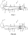
- a removable navigation system 10 for a medical device 12 is provided.
- the medical device 12 is configured for insertion within a lumen in a body such as a blood vessel.
- the system includes a sheath 40, a positioning sensor 32 and a deformable fixation element 20.
- the medical device 12 comprises a catheter.
- a catheter is a tube that is inserted into a body cavity (not shown), duct (not shown) or vessel (not shown). Catheters thereby allow drainage, injection of fluids or access by surgical instruments as indicated above. It should be understood, however, that system 10 may find use with other medical devices including guide wires, electrical leads, a stent, a stylet, or a needle.
- the medical device 12 may typically have an elongate shape and include a distal end 16 and a proximal end 18. Device 12 may be tubular and define a lumen 22 open at one end. The open lumen 22 allows for the delivery of food, access by surgical instruments, or the drainage of fluid from the opening at the distal end 16 of device 12.
- the medical device 12 also includes a hub 42 which may be located at proximal end 18.
- the catheter may be formed of any suitable tubing. Portions of the catheter, such as a portion 24 proximate the distal end 16, may be made from a relatively soft material have a flex modulus. The soft material at the distal end 16 and at the region proximal to the distal end 16 allows the catheter 12 to be atraumatic . Stiffer material in the region 28 between the proximal end 18 and the region proximal to the distal end 16 allows the catheter to have greater pushability and maneuverability during insertion than if a softer material was included in this region of the catheter. The stiffer region 28 of the catheter may have a flex modulus which is generally greater than the area having relatively soft material.
- the walls of the catheter may contain a reinforcing material.
- the walls of a catheter may contain an MRI compatible reinforcing material such as a fiber, monofilament, or non-ferrous metal. This allows the catheter to have a thin wall, while maintaining the desired inner diameter.
- a reinforcing material in the catheter may also provide kinking-resistance or crush-resistance to the catheter as the catheter is traveling through or within a patient's body.
- a reinforcing material within the catheter also allows the catheter to be especially resistant to tearing, thereby facilitating the use of a plunger to purge a clogged catheter without risk of damaging the catheter, even when the catheter is conforming to a tortuous path within a patient's body.
- Suitable reinforcing materials are stiff, MRI-compatible, i.e. non-ferrous materials such as, polyester, copper, aluminum, non-magnetic steel, or other non-ferrous material is polyester monofilament.
- the reinforcing material can by any stiff non-ferromagnetic material such as copper or other monofilament materials. It is also to be understood that a combination of nonstiff material may also lead to a stiff section by constructing or concentrating the nonstiff material in a manner wherein the nonstiff material is operatively configured to be shaped or interact in a manner that stiffens the section.
- a guide wire 26 whose diameter is substantially smaller than that of the catheter, is guided through the body lumen to the operational site before inserting the catheter, and then the catheter is passed over the guide wire 26 and guided to the target operational site.
- Methods and systems for maneuvering the guide wire 26 through a lumen of a patient to the operational sites are known in the art.
- an operator manipulates the movements of the guide wire 26 by manually pushing or pulling the guide wire 26 or twisting the guide wire 26, while he watches an image of the tip of the guide wire 26 against a real time two-dimensional image of the lumen (e.g. by employing fluoroscopy angiogram).
- the tip of the guide wire 26 may be maneuvered at various bifurcations of the lumens, in order to reach the target operational site.
- the same method is employed for manipulating a catheter, only that a marker (e.g. an X-ray opaque material) may be located within a distal end of the catheter.
- the guide wire 26 may be inserted through a site such as, but not limited to the groin or neck of a patient.
- the guide wire 26 may be routed to a target site within the patient's body.
- the guide wire 26 may be formed from stainless steel, nitinol, polymers, braided polymers or the like.
- a medical device 12 in accordance with the present invention may be located using guide wire 26 in one of two ways: (1) the "over-the-wire" guide wire method; and (2) the rapid-exchange method.
- the "over the wire” method device 12 is mounted over the guide wire 26, the guide wire 26 extending inside device 12 throughout its length. As the distal end 16 of device 12 and the distal end of the guide wire 26 are located inside the body, the operator advances device 12 over the guide wire 26 by pushing device 12 from its proximal end 18, which is outside the patient's body.
- the “rapid-exchange” (sometimes also called “monorail” or Single Operator Exchange - SOE) catheterization method
- device 12 is engaged to the guide wire 26 through the open end of lumen 22 at distal end 16, whereas most of the body of device 12 lies adjacent the guide wire 26 (but not over it), so that the device 12 can be quickly replaced with another (hence the name "rapid- exchange”).
- the guide wire exit port on the catheter should be aligned with a guide wire exit port 14 located on the sheath (i.e. the sheath has to have a designated area with a hole (cut-out shown as guide wire exit port 14) specially designed to allow the guide wire to pass through.
- a torque device may be used to stir and rotate the guide wire.
- the guide wire is followed by a catheter (the small diameter, thin wall flexible tube) which is then inserted through a small hole made in an area such as the femoral artery in the groin area.
- the guide wire is then slowly fed through the femoral artery hole and then is slowly maneuvered though the vascular system to an operating site. In moving toward the site, the guide wire is often steered around sharp corners and through small openings.
- the steering may be done by using a guide wire with a bend at the tip and by rotating the wire or "torqueing" the wire and feeding the wire forward as it is carefully maneuvered into position.
- guide wire 26 may be used to direct device 12 to the target site within a patient's body.
- the guide wire 26 is initially inserted into the body lumen and a user is required to navigate the distal end 30 of the guide wire 26 to the target location (and even some distance further beyond). Once the guide wire 26 reaches the target location, the catheter or other medical device 12 is engaged to the guide wire 26 and advanced to the target location.
- a removable sheath 40 is externally installed over the medical device 12 (e.g., a catheter).
- the removable sheath 40 may be made out of polymers, a polymer and braid combination, a stainless steel hypotube, nitinol hypotube, or a combination of the foregoing or like material or combinations of like material. Such materials may be designed with varying degrees of trackability and torque. Moreover, these materials can be made to resist kinking in the most intricate, demanding medical procedure.
- the removable sheath 40 may be tubular and may conform with the inner or outer contour of the medical device 12 to facilitate the ease of guiding the medical device 12 through the patient's body to the target site. Also, as shown in FIG. 1 , the sheath 40 may have an open lumen 36 which allows the distal end 30 of the guide wire 26 to pass through the sheath 40.
- the sheath 40 of the present disclosure is operatively configured to cover at least a portion of a medical device 12.
- the sheath 40 may cover or enclose the medical device 12.
- the sheath 40 may cover only a portion of the medical device 12.
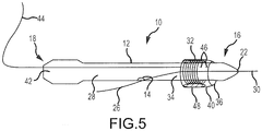
- the covered portion of the medical device 12 may be the distal end 16, a portion 34 of the medical device 12 intermediate the distal end 16 and proximal end 18 (as shown in FIG. 5 ), the proximal end 18, or a combination of areas of the medical device 12.
- the sheath 40 is operatively configured to be removed from the medical device 12 while the sheath 40 and medical device 12 are disposed within the lumen of the body in the case, for example, where the medical device is to be implanted within the body.
- the sheath 40 may have perforations 46 which allow the sheath 40 to be easily removed from the medical device 12 once the medical device 12 reaches the target area.
- the perforations 46 allow the sheath 40 to easily break apart at the perforations 46 when a user pulls the sheath 40 away from the medical device 12.
- perforations 46 are disposed longitudinally along sheath 40. It should be understood, however, that perforations 46 could be arranged in different patterns. The perforation is used to cut the sheath in half in cases such as lead placement for a pacemaker or CRT.
- the sheath 40 may have a weakened area 46' where the sheath 40 thickness is smaller than the overall sheath thickness along the longitudinal direction of the sheath. Upon reaching the target site in the patient's body, the sheath 40 may be easily removed from the medical device 12 by pulling the sheath 40 away from the medical device 12.
- the weakened area 46' of the sheath 40 allows the sheath 40 to break apart so that the sheath 40 may be removed.
- the sheath 40 may include an extended section 44 or portion that remains outside of the patient's body thereby allowing a user to pull on the sheath 40 so that the sheath 40 breaks away from the medical device 12.
- a blade may be coupled with the medical device 12 to pierce the sheath 40 to allow for extraction of the sheath 40 from the patient's body.
- the blade may comprise the commercially available slitter such as the Saint Jude Medical CPSTM Slitter. Cutting starts at the proximal end of the device, or in this non-limiting example, the catheter hub. The blade is kept stationary with one hand and the sheath to be cut is pulled out of the body with other hand towards the physician torso. The slitting cuts the sheath in half releasing it from the body leaving the medical device or catheter in the body.
- the removable navigation system 10 may also include a positioning sensor 32.
- the positioning sensor 32 may be disposed or embedded within the sheath 40 material (as shown in FIG. 1 ). Alternatively, the positioning sensor 32 may be affixed to the interior or the exterior of the sheath 40.
- a non-limiting example of a positioning sensor 32 of the present disclosure may be a hollow electromagnetic coil as shown in FIG. 1 .
- the positioning sensor 32 may surround the medical device 12 and communicate with the navigation system 10 to notify the user of the location of the medical device 12. Conductors would extend along or in the sheath back to an external signal processing unit.
- the coil can be passive and measure induced voltage generated by the magnetic field. It requires transferring the signal either by a form of conductor or wirelessly.
- the removable navigation system 10 of the present disclosure further includes a deformable fixation element 20.
- the fixation element 20 Upon deformation, the fixation element 20 temporarily affixes the sheath 40 to the medical device 12, to eliminate relative motion there between, during the navigation process of the medical device 12 to the target site.
- the fixation element 20 may be disposed on the sheath 40 or may be disposed on the medical device 12. It is to be understood that the fixation element 20 may be positioned proximally or distally to the sensor 32. The fixation element 20 may also be positioned at the sensor 32 as shown in FIG. 2A .
- the fixation element 20 Upon actuation or engagement, the fixation element 20 is operatively configured to engage the sheath 40 to the medical device 12 in order to maintain the sheath 40 into its position on the medical device 12.
- the fixation element 20 may surround the entire circumference of medical device 12 or only a portion thereof.
- the fixation element 20 may assume a variety of forms.
- the fixation element may comprise a shape memory alloy 25 such as Nitinol.
- the shape memory alloy 25 may be configured in the manufacturing process so that it locks the sheath 40 to the medical device 12 when the shape memory alloy is actuated.
- the sheath 40 may be pulled back in a way that will expose the shape memory alloy 25 in a manner that causes the shape memory alloy to lock the sheath 40 on the device 12.
- the sheath 40 may be pushed back into place.
- the contained shape memory alloy may be pushed out from a lumen 21 in the medical device 12 to fixate the sheath 40 and then pulled back from the lumen 32 to release the lock on the sheath 40.
- the fixation element may alternatively comprise pressurized ferrule 48.
- a ferrule 48 may be implemented by applying pressure on a side of a polymeric washer such that it will expand on its outer diameter and shrink about its inner diameter.
- FIG. 2B illustrates a cross-sectional view of the medical device 12, the sheath 40 and the ferrule 48 along lines AB in FIG. 2A before the ferrule 48 expands.
- the sheath 40 may be integral with or affixed to the outer side of the ferrule.
- FIG. 2C illustrates the same cross section along lines AB of FIG. 2A when the ferrule is pressurized and expands such that the sheath 40 will not move relative to the medical device 12 due to the expanded ferrule 48 holding the sheath 40 in place.
- the fixation element 20 may be an inflatable balloon 50 or other expandable/collapsible element that may expand to secure the sheath 40 in position and contract to release the sheath 40 from position.
- the inflatable balloon 50 may be positioned on the internal wall of the sheath 40 at the sensor 32 area (proximally, distally, or at).
- the inflatable balloon 50 (shown in FIG. 3 ) may surround the medical device 12. It is also to be understood that an array of small balloons 52 (shown in FIG. 4 ) may be located circumferentially such that once expanded, the array of balloons lock the sheath 40 into place.
- the fixation element 20 may alternatively comprise a mechanical locking device 54.
- Device 54 is configured to cooperate with a corresponding structure mounted on, projecting from, or formed in the body of device 12.
- device 54 may comprise a one or more tabs 55 configured to engage corresponding detents 56 in device 12.
- Device 54 may alternatively comprise pincers configured to engage corresponding apertures in the body of device 12.
- Device 54 may be deformed or actuated by movement of a pull wire 57 extending from device 54 through sheath 40 to the proximal end of sheath 40.
- the particular mechanical structures described above are exemplary only and a variety of deformable mechanical structures could be used to lock sheath 40 and device 12 into position relative to one another. Further, it should be understood that the relative positions of various mechanical locking components could be reversed as to the sheath 40 and device 12 (e.g., with tabs 55 on device 12 engaging detents 56 formed in sheath 40).
- the fixation element 20 may alternatively comprise an electromechanical locking device 58.
- Device 58 is again configured to cooperate with a corresponding structure mounted on, projecting from, or formed in the body of device 12.
- device 58 may comprise a one or more electromagnets 59 configured to draw a ferromagnetic structure 60 into engagement with the electromagnets 59 upon energization of the electromagnets 59.
- Structure 60 may, for example be coupled to device 12 by a compression spring 61.
- Electromagnets 59 may be energized by passing current through a conductor 62 extending from electromagnets 59 through sheath 40 to the proximal end of sheath 40.
- electromechanical structure described above is exemplary only and a variety of deformable electromechanical structures could be used to lock sheath 40 and device 12 into position relative to one another. Further, it should be understood that the relative positions of various electromechanical locking components could be reversed as to the sheath 40 and device 12 (e.g., with electromagnets 59 on device 12 engaging ferromagnetic structures 60 on sheath 40).
- the present disclosure provides a low-cost and simple method to equip a medical device 12 with a navigation system 10 such that the medical device's 12 physical and cost characteristics are not hindered by the navigation system 10.
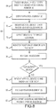
- the method may begin with the step 64 of inserting a medical device 12 into a sheath 40.
- the sheath 40 preferably includes a positioning sensor 32 embedded therein or thereon.
- the method may continue with the step 66 of deforming a deformable fixation element 20 disposed between the sheath 40 and the medical device 12 to temporarily fix a position of the medical device 12 relative to the sheath 40 and positioning sensor 32.
- fixation element 20 may expand in size or force to prevent relative motion between the sheath 40 and medical device 12.
- the method may continue with the step 68 of guiding the medical device 12 and sheath 40 to a location within a lumen of a body.
- this step may include the substeps 70, 72 of mounting the medical device and the sheath onto a guide wire and directing the medical device 12 to a location within a lumen of a patient's body.
- the method may further include the step 74 of monitoring a position of the positioning sensor 32 within the body using a conventional navigation system such as the navigation and tracking system sold under the registered trademark "ENSITE NAVX" by St. Jude Medical, Inc. or a magnetic tracking system such as the system sold under the registered trademark "gMPS" by St. Jude Medical Inc.
- the method may further include the step 76 of performing a medical procedure.
- the method may include the step 78 of removing the sheath 40 and medical device 12 from the patient's body and the step 80 of releasing the fixation element.
- the method may include the step 82 of separating the sheath 40 and sensor 32 from the device 12 as discussed above.
- the sheath may be removed prior to commencing the medical procedure. Therefore, once the medical device is in the desired location, the fixation element may release the sheath and the sheath may be pulled back or perforated and pulled away/removed to allow for treatments such as, but not limited to, a balloon catheter where the inflation of balloon is required for stent placement.
- joinder references do not necessarily infer that two elements are directly connected and in fixed relation to each other. It is intended that all matter contained in the above description or shown in the accompanying drawings shall be interpreted as illustrative only and not as limiting. Changes in detail or structure may be made without departing from the invention as defined in the appended claims.
Claims (13)
- Système de navigation amovible (10) pour un dispositif médical (12) configuré pour être inséré à l'intérieur d'une lumière dans un corps, le système de navigation amovible (10) comprenant:un dispositif médical (12) ;une enveloppe (40) configurée fonctionnellement pour couvrir au moins une partie du dispositif médical (12) ;un capteur de positionnement (32) comprenant une bobine électromagnétique fixée à l'intérieur du matériau de l'enveloppe (40) ; etun élément de fixation déformable (20) disposé entre l'enveloppe (40) et le dispositif médical (12), l'élément de fixation déformable (20) configuré pour être déformé fonctionnellement pour fixer temporairement une position du dispositif médical (12) par rapport à l'enveloppe (40) et au capteur de positionnement (32),dans lequel l'enveloppe comprend une première ouverture, une seconde ouverture et une lumière entre celles-ci, où la première ouverture, la seconde ouverture et la lumière sont chacune dimensionnée et configurée de sorte qu'une partie du dispositif médical (12) puisse les traverser,dans lequel la bobine électromagnétique est dimensionnée et configurée de sorte qu'une partie du dispositif médical (12) puisse traverser la bobine électromagnétique,dans lequel la bobine électromagnétique est configurée pour produire un signal pouvant être interprété par une unité de traitement de signal, etdans lequel l'élément de fixation déformable comprend l'un des éléments suivants :(i) un alliage à mémoire de forme (25),(ii) une virole sous pression (48),(iii) un élément expansible et pliable, de préférence un ballon gonflable (50),dans lequel de préférence le ballon gonflable (50) entoure le dispositif médical (12) ou un réseau de petits ballons (52) est situé circonférentiellement,(iv) un dispositif de verrouillage mécanique (54), et(v) un dispositif de verrouillage électromécanique (58).
- Système de navigation amovible (10) selon la revendication 1, dans lequel l'enveloppe (40) est configurée fonctionnellement pour être séparée du dispositif médical (12) tandis que le système (10) est disposé à l'intérieur de la lumière dans le corps.
- Système de navigation amovible (10) selon la revendication 2, dans lequel l'enveloppe (40) définit des perforations (46) configurées pour permettre à des parties de l'enveloppe de se détacher les unes des autres.
- Système de navigation amovible (10) selon la revendication 2, dans lequel l'enveloppe (40) définit une partie (46') qui est affaiblie par rapport aux autres parties de l'enveloppe (40) pour permettre à la partie qui est affaiblie de se détacher des autres parties de l'enveloppe.
- Système de navigation amovible (10) tel que défini dans l'une quelconque des revendications précédentes, dans lequel la partie du dispositif médical (12) comprend une partie de l'extrémité distale (16) du dispositif médical (12).
- Système de navigation amovible (10) tel que défini dans l'une quelconque des revendications précédentes, dans lequel la bobine électromagnétique est configurée pour produire un signal comprenant une tension induite lorsque soumis à un champ magnétique externe.
- Système de navigation amovible (10) tel que défini dans l'une quelconque des revendications précédentes, dans lequel la bobine électromagnétique est configurée pour produire un signal pouvant être interprété par une unité de traitement de signal afin de déterminer un emplacement de la bobine électromagnétique.
- Système de navigation amovible (10) tel que défini dans l'une quelconque des revendications précédentes, comprenant en outre une unité de traitement de signal configurée pour mesurer une tension induite produite par la bobine électromagnétique.
- Système de navigation amovible (10) tel que défini dans l'une quelconque des revendications précédentes, comprenant en outre des conducteurs s'étendant depuis la bobine électromagnétique jusqu'au-delà d'un extérieur du dispositif médical.
- Système de navigation amovible (10) tel que défini dans l'une quelconque des revendications précédentes, dans lequel l'enveloppe est rigide de manière à maintenir un diamètre intérieur.
- Système de navigation amovible (10) tel que défini dans l'une quelconque des revendications précédentes, dans lequel l'élément de fixation déformable vient en prise avec l'enveloppe et le dispositif médical pour fixer temporairement une position du dispositif médical au moins partiellement à l'intérieur de l'enveloppe.
- Système de navigation amovible (10) tel que défini dans l'une quelconque des revendications précédentes, dans lequel l'élément de fixation déformable est situé de manière à être disposé radialement entre l'enveloppe et le dispositif médical ou disposé à une extrémité proximale de l'enveloppe.
- Système de navigation amovible (10) tel que défini dans l'une quelconque des revendications précédentes, dans lequel le dispositif médical (12) est un cathéter.
Applications Claiming Priority (2)
| Application Number | Priority Date | Filing Date | Title |
|---|---|---|---|
| US12/843,095 US10390889B2 (en) | 2010-07-26 | 2010-07-26 | Removable navigation system and method for a medical device |
| PCT/US2011/040034 WO2012018435A1 (fr) | 2010-07-26 | 2011-06-10 | Système de navigation amovible d'un dispositif médical et méthode associée |
Publications (3)
| Publication Number | Publication Date |
|---|---|
| EP2574173A1 EP2574173A1 (fr) | 2013-04-03 |
| EP2574173A4 EP2574173A4 (fr) | 2016-04-13 |
| EP2574173B1 true EP2574173B1 (fr) | 2018-11-07 |
Family
ID=45492539
Family Applications (1)
| Application Number | Title | Priority Date | Filing Date |
|---|---|---|---|
| EP11814942.6A Active EP2574173B1 (fr) | 2010-07-26 | 2011-06-10 | Système de navigation amovible d'un dispositif médical |
Country Status (4)
| Country | Link |
|---|---|
| US (1) | US10390889B2 (fr) |
| EP (1) | EP2574173B1 (fr) |
| JP (1) | JP5848347B2 (fr) |
| WO (1) | WO2012018435A1 (fr) |
Families Citing this family (12)
| Publication number | Priority date | Publication date | Assignee | Title |
|---|---|---|---|---|
| US10045811B2 (en) * | 2011-02-16 | 2018-08-14 | Covidien Lp | Surgical instrument with dispensable components |
| US11202704B2 (en) | 2011-10-19 | 2021-12-21 | Twelve, Inc. | Prosthetic heart valve devices, prosthetic mitral valves and associated systems and methods |
| US9821143B2 (en) | 2011-12-15 | 2017-11-21 | Imricor Medical Systems, Inc. | Steerable sheath including elastomeric member |
| US9757538B2 (en) | 2011-12-15 | 2017-09-12 | Imricor Medical Systems, Inc. | MRI compatible control handle for steerable sheath with audible, tactile and/or visual means |
| WO2013090558A1 (fr) | 2011-12-15 | 2013-06-20 | Imricor Medical Systems, Inc. | Poignée compatible avec l'irm et gaine orientable |
| CN105979899B (zh) * | 2013-12-09 | 2019-10-01 | 直观外科手术操作公司 | 用于设备感知柔性工具配准的系统和方法 |
| EP3137148B1 (fr) | 2014-05-02 | 2021-12-22 | Intellimedical Technologies Pty Ltd | Dispositifs orientables allongés à introduire dans le corps d'un sujet |
| JP6734282B2 (ja) | 2015-01-22 | 2020-08-05 | コーニンクレッカ フィリップス エヌ ヴェKoninklijke Philips N.V. | 予め組み込まれた又は取り外し可能な光学形状検知アタッチメントによるエンドグラフトの視覚化 |
| US10905329B2 (en) * | 2016-06-09 | 2021-02-02 | Biosense Webster (Israel) Ltd. | Multi-function conducting elements for a catheter |
| US11975157B2 (en) | 2019-04-12 | 2024-05-07 | Covidien Lp | Method of manufacturing an elongated catheter having multiple sensors for three-dimensional location of the catheter |
| KR102161401B1 (ko) * | 2020-04-02 | 2020-09-29 | (주)메가메디칼 | 카테터 위치 변화에 대응하여 결정된 정보를 표시하는 네비게이션 |
| KR102161402B1 (ko) * | 2020-04-02 | 2020-09-29 | (주)메가메디칼 | 풍선 카테터와 연동하는 무선 방식의 네비게이션 |
Family Cites Families (44)
| Publication number | Priority date | Publication date | Assignee | Title |
|---|---|---|---|---|
| US5040548A (en) | 1989-06-01 | 1991-08-20 | Yock Paul G | Angioplasty mehtod |
| US4913164A (en) * | 1988-09-27 | 1990-04-03 | Intermedics, Inc. | Extensible passive fixation mechanism for lead assembly of an implantable cardiac stimulator |
| US4932959A (en) | 1988-12-01 | 1990-06-12 | Advanced Cardiovascular Systems, Inc. | Vascular catheter with releasably secured guidewire |
| US5318532A (en) * | 1989-10-03 | 1994-06-07 | C. R. Bard, Inc. | Multilumen catheter with variable cross-section lumens |
| US5257617A (en) | 1989-12-25 | 1993-11-02 | Asahi Kogaku Kogyo Kabushiki Kaisha | Sheathed endoscope and sheath therefor |
| US5163911A (en) | 1990-10-31 | 1992-11-17 | Baxter International Inc. | Over-the-wire catheter |
| US5645533A (en) | 1991-07-05 | 1997-07-08 | Scimed Life Systems, Inc. | Apparatus and method for performing an intravascular procedure and exchanging an intravascular device |
| US5353795A (en) | 1992-12-10 | 1994-10-11 | General Electric Company | Tracking system to monitor the position of a device using multiplexed magnetic resonance detection |
| US5558091A (en) | 1993-10-06 | 1996-09-24 | Biosense, Inc. | Magnetic determination of position and orientation |
| US5598844A (en) | 1995-08-03 | 1997-02-04 | Cordis Corporation | Device for flushing a guidewire receiving lumen of a monorail or rapid exchange catheter |
| US5603694A (en) * | 1995-10-17 | 1997-02-18 | Brown; Joe E. | Infusion coil apparatus and method for delivering fluid-based agents intravascularly |
| WO1997029679A2 (fr) | 1996-02-15 | 1997-08-21 | Biosense Inc. | Procede de determination de la position precise d'endoscopes |
| US5935098A (en) | 1996-12-23 | 1999-08-10 | Conceptus, Inc. | Apparatus and method for accessing and manipulating the uterus |
| WO1998036790A1 (fr) | 1997-02-19 | 1998-08-27 | Condado Medical Devices Corporation | Catheters polyvalents, systemes de catheter et traitement par rayonnement |
| US5891137A (en) * | 1997-05-21 | 1999-04-06 | Irvine Biomedical, Inc. | Catheter system having a tip with fixation means |
| DE19736030A1 (de) | 1997-08-20 | 1999-02-25 | Philips Patentverwaltung | Verfahren zur Navigation eines magnetischen Objektes und MR-Anordung |
| US6179811B1 (en) * | 1997-11-25 | 2001-01-30 | Medtronic, Inc. | Imbedded marker and flexible guide wire shaft |
| US6126647A (en) * | 1999-05-17 | 2000-10-03 | Hermetic Switch, Inc. | Magnetically guided catheter with sensor |
| US6233476B1 (en) | 1999-05-18 | 2001-05-15 | Mediguide Ltd. | Medical positioning system |
| WO2001073461A2 (fr) * | 2000-03-24 | 2001-10-04 | Surgi-Vision | Dispositif, systemes et procedes d'imagerie par resonance magnetique in vivo |
| JP2001275942A (ja) | 2000-03-31 | 2001-10-09 | Olympus Optical Co Ltd | 内視鏡固定具 |
| US6533772B1 (en) | 2000-04-07 | 2003-03-18 | Innex Corporation | Guide wire torque device |
| US6442413B1 (en) * | 2000-05-15 | 2002-08-27 | James H. Silver | Implantable sensor |
| US6785571B2 (en) | 2001-03-30 | 2004-08-31 | Neil David Glossop | Device and method for registering a position sensor in an anatomical body |
| AU2003223749A1 (en) | 2002-04-25 | 2003-11-10 | The Board Of Trustees Of The Leland Stanford Junior University | Expandable guide sheath and apparatus and methods using such sheaths |
| US7881769B2 (en) | 2002-11-18 | 2011-02-01 | Mediguide Ltd. | Method and system for mounting an MPS sensor on a catheter |
| WO2004078066A2 (fr) * | 2003-03-03 | 2004-09-16 | Sinus Rhythm Technologies, Inc. | Dispositif de positionnement de blocs electriques et procedes d'utilisation dudit dispositif |
| US20040230282A1 (en) * | 2003-04-11 | 2004-11-18 | Cates Adam W. | Acute and chronic fixation for subcutaneous electrodes |
| US20040220471A1 (en) * | 2003-04-29 | 2004-11-04 | Yitzhack Schwartz | Method and device for transseptal facilitation using location system |
| US20070208252A1 (en) * | 2004-04-21 | 2007-09-06 | Acclarent, Inc. | Systems and methods for performing image guided procedures within the ear, nose, throat and paranasal sinuses |
| US7197354B2 (en) | 2004-06-21 | 2007-03-27 | Mediguide Ltd. | System for determining the position and orientation of a catheter |
| US7713210B2 (en) * | 2004-11-23 | 2010-05-11 | St. Jude Medical, Atrial Fibrillation Division, Inc. | Method and apparatus for localizing an ultrasound catheter |
| US7532932B2 (en) * | 2005-03-08 | 2009-05-12 | Kenergy, Inc. | Implantable medical apparatus having an omnidirectional antenna for receiving radio frequency signals |
| US20080091193A1 (en) * | 2005-05-16 | 2008-04-17 | James Kauphusman | Irrigated ablation catheter having magnetic tip for magnetic field control and guidance |
| EP1906858B1 (fr) | 2005-07-01 | 2016-11-16 | Hansen Medical, Inc. | Systeme de catheter robotique |
| DE102005050344A1 (de) * | 2005-10-20 | 2007-05-03 | Siemens Ag | Kryokatheter zur Einführung in ein Körpergefäß sowie medizinische Untersuchungs- und Behandlungsvorrichtung |
| US20070118079A1 (en) | 2005-11-21 | 2007-05-24 | Moberg John R | Medical devices and related systems and methods |
| EP2026850B1 (fr) * | 2006-05-23 | 2014-07-09 | Providence Health System-Oregon d/b/a Providence St. Vincent Medical Center | Systèmes et procédés pour introduire et appliquer une structure de pansement à l'intérieur d'une lumière corporelle ou d'un organe corporel creux |
| US7684873B2 (en) * | 2006-10-31 | 2010-03-23 | Medtronic, Inc. | Implantable medical lead including a directional electrode and fixation elements along an interior surface |
| US20080171989A1 (en) * | 2007-01-16 | 2008-07-17 | Bell Stephen G | Trans Urinary Bladder Access Device and Method |
| AU2008292840B2 (en) | 2007-08-30 | 2011-09-15 | Syncro Medical Innovations, Inc. | Guided catheter with removable magnetic guide |
| US20090112221A1 (en) * | 2007-10-25 | 2009-04-30 | Disc Dynamics, Inc. | System and method for measuring the shape of internal body cavities |
| WO2010057082A2 (fr) * | 2008-11-17 | 2010-05-20 | Mayo Foundation For Medical Education And Research | Capsules diagnostiques, systèmes de distribution/extraction, kits et procédés |
| US8504139B2 (en) | 2009-03-10 | 2013-08-06 | Medtronic Xomed, Inc. | Navigating a surgical instrument |
-
2010
- 2010-07-26 US US12/843,095 patent/US10390889B2/en active Active
-
2011
- 2011-06-10 JP JP2013521784A patent/JP5848347B2/ja active Active
- 2011-06-10 WO PCT/US2011/040034 patent/WO2012018435A1/fr active Application Filing
- 2011-06-10 EP EP11814942.6A patent/EP2574173B1/fr active Active
Non-Patent Citations (1)
| Title |
|---|
| None * |
Also Published As
| Publication number | Publication date |
|---|---|
| JP5848347B2 (ja) | 2016-01-27 |
| US20120017923A1 (en) | 2012-01-26 |
| US10390889B2 (en) | 2019-08-27 |
| WO2012018435A1 (fr) | 2012-02-09 |
| EP2574173A4 (fr) | 2016-04-13 |
| EP2574173A1 (fr) | 2013-04-03 |
| JP2013535273A (ja) | 2013-09-12 |
Similar Documents
| Publication | Publication Date | Title |
|---|---|---|
| EP2574173B1 (fr) | Système de navigation amovible d'un dispositif médical | |
| US9956378B2 (en) | Catheter assembly | |
| EP2613686B1 (fr) | Dispositifs médicaux sur lesquels est monté un élément d'imagerie d'un système électroanatomique | |
| US6817364B2 (en) | Magnetically navigated pacing leads, and methods for delivering medical devices | |
| US20120010490A1 (en) | Medical devices having flexible electrodes mounted thereon | |
| US20120130217A1 (en) | Medical devices having electrodes mounted thereon and methods of manufacturing therefor | |
| EP3056161A1 (fr) | Fil-guide d'angioplastie | |
| US20030229386A1 (en) | Catheter systems and methods for placing bi-ventricular pacing leads | |
| US20120172717A1 (en) | Deflectable medical devices and methods of manufacturing therefor | |
| EP2704631A1 (fr) | Cathéter à capteurs de position électromagnétiques, système de localisation, cathéters, et fils de guidage | |
| JP5838093B2 (ja) | 固定カテーテルシース | |
| EP2528517A1 (fr) | Dispositif de prélèvement pouvant être façonné et son procédé d'utilisation | |
| WO2014037836A1 (fr) | Guide pour dispositif intravasculaire | |
| US20220379079A1 (en) | Catheter tube for a steerable catheter, and method for implanting an implantable medical device by means of a steerable catheter | |
| EP3539500B1 (fr) | Manchon de navigation pour instrument médical | |
| EP3998976B1 (fr) | Cathéter comprenant une tige déformable et ses procédés d'assemblage | |
| EP3863534B1 (fr) | Outil de récupération de dispositif médical à courbe réglable | |
| JP2018157913A (ja) | 医療用デバイス |
Legal Events
| Date | Code | Title | Description |
|---|---|---|---|
| PUAI | Public reference made under article 153(3) epc to a published international application that has entered the european phase |
Free format text: ORIGINAL CODE: 0009012 |
|
| 17P | Request for examination filed |
Effective date: 20121227 |
|
| AK | Designated contracting states |
Kind code of ref document: A1 Designated state(s): AL AT BE BG CH CY CZ DE DK EE ES FI FR GB GR HR HU IE IS IT LI LT LU LV MC MK MT NL NO PL PT RO RS SE SI SK SM TR |
|
| DAX | Request for extension of the european patent (deleted) | ||
| RA4 | Supplementary search report drawn up and despatched (corrected) |
Effective date: 20160310 |
|
| RIC1 | Information provided on ipc code assigned before grant |
Ipc: A61M 25/095 20060101AFI20160304BHEP Ipc: A61B 17/00 20060101ALN20160304BHEP Ipc: A61B 34/20 20160101ALI20160304BHEP |
|
| STAA | Information on the status of an ep patent application or granted ep patent |
Free format text: STATUS: EXAMINATION IS IN PROGRESS |
|
| 17Q | First examination report despatched |
Effective date: 20170210 |
|
| RAP1 | Party data changed (applicant data changed or rights of an application transferred) |
Owner name: ST. JUDE MEDICAL INTERNATIONAL HOLDING S.A R.L. |
|
| GRAP | Despatch of communication of intention to grant a patent |
Free format text: ORIGINAL CODE: EPIDOSNIGR1 |
|
| STAA | Information on the status of an ep patent application or granted ep patent |
Free format text: STATUS: GRANT OF PATENT IS INTENDED |
|
| INTG | Intention to grant announced |
Effective date: 20180622 |
|
| GRAS | Grant fee paid |
Free format text: ORIGINAL CODE: EPIDOSNIGR3 |
|
| GRAA | (expected) grant |
Free format text: ORIGINAL CODE: 0009210 |
|
| STAA | Information on the status of an ep patent application or granted ep patent |
Free format text: STATUS: THE PATENT HAS BEEN GRANTED |
|
| RAP1 | Party data changed (applicant data changed or rights of an application transferred) |
Owner name: ST. JUDE MEDICAL INTERNATIONAL HOLDING S.A R.L. |
|
| AK | Designated contracting states |
Kind code of ref document: B1 Designated state(s): AL AT BE BG CH CY CZ DE DK EE ES FI FR GB GR HR HU IE IS IT LI LT LU LV MC MK MT NL NO PL PT RO RS SE SI SK SM TR |
|
| REG | Reference to a national code |
Ref country code: GB Ref legal event code: FG4D |
|
| REG | Reference to a national code |
Ref country code: CH Ref legal event code: EP Ref country code: AT Ref legal event code: REF Ref document number: 1061353 Country of ref document: AT Kind code of ref document: T Effective date: 20181115 |
|
| REG | Reference to a national code |
Ref country code: IE Ref legal event code: FG4D |
|
| REG | Reference to a national code |
Ref country code: DE Ref legal event code: R096 Ref document number: 602011053699 Country of ref document: DE |
|
| REG | Reference to a national code |
Ref country code: NL Ref legal event code: MP Effective date: 20181107 |
|
| REG | Reference to a national code |
Ref country code: LT Ref legal event code: MG4D |
|
| REG | Reference to a national code |
Ref country code: AT Ref legal event code: MK05 Ref document number: 1061353 Country of ref document: AT Kind code of ref document: T Effective date: 20181107 |
|
| PG25 | Lapsed in a contracting state [announced via postgrant information from national office to epo] |
Ref country code: LV Free format text: LAPSE BECAUSE OF FAILURE TO SUBMIT A TRANSLATION OF THE DESCRIPTION OR TO PAY THE FEE WITHIN THE PRESCRIBED TIME-LIMIT Effective date: 20181107 Ref country code: NO Free format text: LAPSE BECAUSE OF FAILURE TO SUBMIT A TRANSLATION OF THE DESCRIPTION OR TO PAY THE FEE WITHIN THE PRESCRIBED TIME-LIMIT Effective date: 20190207 Ref country code: LT Free format text: LAPSE BECAUSE OF FAILURE TO SUBMIT A TRANSLATION OF THE DESCRIPTION OR TO PAY THE FEE WITHIN THE PRESCRIBED TIME-LIMIT Effective date: 20181107 Ref country code: FI Free format text: LAPSE BECAUSE OF FAILURE TO SUBMIT A TRANSLATION OF THE DESCRIPTION OR TO PAY THE FEE WITHIN THE PRESCRIBED TIME-LIMIT Effective date: 20181107 Ref country code: IS Free format text: LAPSE BECAUSE OF FAILURE TO SUBMIT A TRANSLATION OF THE DESCRIPTION OR TO PAY THE FEE WITHIN THE PRESCRIBED TIME-LIMIT Effective date: 20190307 Ref country code: AT Free format text: LAPSE BECAUSE OF FAILURE TO SUBMIT A TRANSLATION OF THE DESCRIPTION OR TO PAY THE FEE WITHIN THE PRESCRIBED TIME-LIMIT Effective date: 20181107 Ref country code: ES Free format text: LAPSE BECAUSE OF FAILURE TO SUBMIT A TRANSLATION OF THE DESCRIPTION OR TO PAY THE FEE WITHIN THE PRESCRIBED TIME-LIMIT Effective date: 20181107 Ref country code: BG Free format text: LAPSE BECAUSE OF FAILURE TO SUBMIT A TRANSLATION OF THE DESCRIPTION OR TO PAY THE FEE WITHIN THE PRESCRIBED TIME-LIMIT Effective date: 20190207 Ref country code: HR Free format text: LAPSE BECAUSE OF FAILURE TO SUBMIT A TRANSLATION OF THE DESCRIPTION OR TO PAY THE FEE WITHIN THE PRESCRIBED TIME-LIMIT Effective date: 20181107 |
|
| PG25 | Lapsed in a contracting state [announced via postgrant information from national office to epo] |
Ref country code: PT Free format text: LAPSE BECAUSE OF FAILURE TO SUBMIT A TRANSLATION OF THE DESCRIPTION OR TO PAY THE FEE WITHIN THE PRESCRIBED TIME-LIMIT Effective date: 20190307 Ref country code: SE Free format text: LAPSE BECAUSE OF FAILURE TO SUBMIT A TRANSLATION OF THE DESCRIPTION OR TO PAY THE FEE WITHIN THE PRESCRIBED TIME-LIMIT Effective date: 20181107 Ref country code: AL Free format text: LAPSE BECAUSE OF FAILURE TO SUBMIT A TRANSLATION OF THE DESCRIPTION OR TO PAY THE FEE WITHIN THE PRESCRIBED TIME-LIMIT Effective date: 20181107 Ref country code: NL Free format text: LAPSE BECAUSE OF FAILURE TO SUBMIT A TRANSLATION OF THE DESCRIPTION OR TO PAY THE FEE WITHIN THE PRESCRIBED TIME-LIMIT Effective date: 20181107 Ref country code: RS Free format text: LAPSE BECAUSE OF FAILURE TO SUBMIT A TRANSLATION OF THE DESCRIPTION OR TO PAY THE FEE WITHIN THE PRESCRIBED TIME-LIMIT Effective date: 20181107 Ref country code: GR Free format text: LAPSE BECAUSE OF FAILURE TO SUBMIT A TRANSLATION OF THE DESCRIPTION OR TO PAY THE FEE WITHIN THE PRESCRIBED TIME-LIMIT Effective date: 20190208 |
|
| PG25 | Lapsed in a contracting state [announced via postgrant information from national office to epo] |
Ref country code: PL Free format text: LAPSE BECAUSE OF FAILURE TO SUBMIT A TRANSLATION OF THE DESCRIPTION OR TO PAY THE FEE WITHIN THE PRESCRIBED TIME-LIMIT Effective date: 20181107 Ref country code: DK Free format text: LAPSE BECAUSE OF FAILURE TO SUBMIT A TRANSLATION OF THE DESCRIPTION OR TO PAY THE FEE WITHIN THE PRESCRIBED TIME-LIMIT Effective date: 20181107 Ref country code: CZ Free format text: LAPSE BECAUSE OF FAILURE TO SUBMIT A TRANSLATION OF THE DESCRIPTION OR TO PAY THE FEE WITHIN THE PRESCRIBED TIME-LIMIT Effective date: 20181107 |
|
| REG | Reference to a national code |
Ref country code: DE Ref legal event code: R097 Ref document number: 602011053699 Country of ref document: DE |
|
| PG25 | Lapsed in a contracting state [announced via postgrant information from national office to epo] |
Ref country code: RO Free format text: LAPSE BECAUSE OF FAILURE TO SUBMIT A TRANSLATION OF THE DESCRIPTION OR TO PAY THE FEE WITHIN THE PRESCRIBED TIME-LIMIT Effective date: 20181107 Ref country code: EE Free format text: LAPSE BECAUSE OF FAILURE TO SUBMIT A TRANSLATION OF THE DESCRIPTION OR TO PAY THE FEE WITHIN THE PRESCRIBED TIME-LIMIT Effective date: 20181107 Ref country code: SM Free format text: LAPSE BECAUSE OF FAILURE TO SUBMIT A TRANSLATION OF THE DESCRIPTION OR TO PAY THE FEE WITHIN THE PRESCRIBED TIME-LIMIT Effective date: 20181107 Ref country code: SK Free format text: LAPSE BECAUSE OF FAILURE TO SUBMIT A TRANSLATION OF THE DESCRIPTION OR TO PAY THE FEE WITHIN THE PRESCRIBED TIME-LIMIT Effective date: 20181107 |
|
| PLBE | No opposition filed within time limit |
Free format text: ORIGINAL CODE: 0009261 |
|
| STAA | Information on the status of an ep patent application or granted ep patent |
Free format text: STATUS: NO OPPOSITION FILED WITHIN TIME LIMIT |
|
| 26N | No opposition filed |
Effective date: 20190808 |
|
| PG25 | Lapsed in a contracting state [announced via postgrant information from national office to epo] |
Ref country code: SI Free format text: LAPSE BECAUSE OF FAILURE TO SUBMIT A TRANSLATION OF THE DESCRIPTION OR TO PAY THE FEE WITHIN THE PRESCRIBED TIME-LIMIT Effective date: 20181107 |
|
| PG25 | Lapsed in a contracting state [announced via postgrant information from national office to epo] |
Ref country code: MC Free format text: LAPSE BECAUSE OF FAILURE TO SUBMIT A TRANSLATION OF THE DESCRIPTION OR TO PAY THE FEE WITHIN THE PRESCRIBED TIME-LIMIT Effective date: 20181107 |
|
| REG | Reference to a national code |
Ref country code: CH Ref legal event code: PL |
|
| REG | Reference to a national code |
Ref country code: BE Ref legal event code: MM Effective date: 20190630 |
|
| PG25 | Lapsed in a contracting state [announced via postgrant information from national office to epo] |
Ref country code: TR Free format text: LAPSE BECAUSE OF FAILURE TO SUBMIT A TRANSLATION OF THE DESCRIPTION OR TO PAY THE FEE WITHIN THE PRESCRIBED TIME-LIMIT Effective date: 20181107 |
|
| PG25 | Lapsed in a contracting state [announced via postgrant information from national office to epo] |
Ref country code: IE Free format text: LAPSE BECAUSE OF NON-PAYMENT OF DUE FEES Effective date: 20190610 |
|
| PG25 | Lapsed in a contracting state [announced via postgrant information from national office to epo] |
Ref country code: LU Free format text: LAPSE BECAUSE OF NON-PAYMENT OF DUE FEES Effective date: 20190610 Ref country code: LI Free format text: LAPSE BECAUSE OF NON-PAYMENT OF DUE FEES Effective date: 20190630 Ref country code: BE Free format text: LAPSE BECAUSE OF NON-PAYMENT OF DUE FEES Effective date: 20190630 Ref country code: CH Free format text: LAPSE BECAUSE OF NON-PAYMENT OF DUE FEES Effective date: 20190630 |
|
| PG25 | Lapsed in a contracting state [announced via postgrant information from national office to epo] |
Ref country code: CY Free format text: LAPSE BECAUSE OF FAILURE TO SUBMIT A TRANSLATION OF THE DESCRIPTION OR TO PAY THE FEE WITHIN THE PRESCRIBED TIME-LIMIT Effective date: 20181107 |
|
| PG25 | Lapsed in a contracting state [announced via postgrant information from national office to epo] |
Ref country code: HU Free format text: LAPSE BECAUSE OF FAILURE TO SUBMIT A TRANSLATION OF THE DESCRIPTION OR TO PAY THE FEE WITHIN THE PRESCRIBED TIME-LIMIT; INVALID AB INITIO Effective date: 20110610 Ref country code: MT Free format text: LAPSE BECAUSE OF FAILURE TO SUBMIT A TRANSLATION OF THE DESCRIPTION OR TO PAY THE FEE WITHIN THE PRESCRIBED TIME-LIMIT Effective date: 20181107 |
|
| PG25 | Lapsed in a contracting state [announced via postgrant information from national office to epo] |
Ref country code: MK Free format text: LAPSE BECAUSE OF FAILURE TO SUBMIT A TRANSLATION OF THE DESCRIPTION OR TO PAY THE FEE WITHIN THE PRESCRIBED TIME-LIMIT Effective date: 20181107 |
|
| P01 | Opt-out of the competence of the unified patent court (upc) registered |
Effective date: 20230602 |
|
| PGFP | Annual fee paid to national office [announced via postgrant information from national office to epo] |
Ref country code: IT Payment date: 20230612 Year of fee payment: 13 Ref country code: FR Payment date: 20230509 Year of fee payment: 13 Ref country code: DE Payment date: 20230509 Year of fee payment: 13 |
|
| REG | Reference to a national code |
Ref country code: DE Ref legal event code: R082 Ref document number: 602011053699 Country of ref document: DE Representative=s name: ALPSPITZ IP ALLGAYER UND PARTNER PATENTANWAELT, DE |
|
| PGFP | Annual fee paid to national office [announced via postgrant information from national office to epo] |
Ref country code: GB Payment date: 20230510 Year of fee payment: 13 |