EP2573640A1 - Entraînement à ressort doté d'une récupération active dans le circuit de tension continue - Google Patents
Entraînement à ressort doté d'une récupération active dans le circuit de tension continue Download PDFInfo
- Publication number
- EP2573640A1 EP2573640A1 EP11182832A EP11182832A EP2573640A1 EP 2573640 A1 EP2573640 A1 EP 2573640A1 EP 11182832 A EP11182832 A EP 11182832A EP 11182832 A EP11182832 A EP 11182832A EP 2573640 A1 EP2573640 A1 EP 2573640A1
- Authority
- EP
- European Patent Office
- Prior art keywords
- motor
- energy
- rotor
- control device
- switching
- Prior art date
- Legal status (The legal status is an assumption and is not a legal conclusion. Google has not performed a legal analysis and makes no representation as to the accuracy of the status listed.)
- Granted
Links
- 238000011084 recovery Methods 0.000 title description 2
- 239000003990 capacitor Substances 0.000 claims abstract description 55
- 238000006073 displacement reaction Methods 0.000 claims description 3
- 230000004044 response Effects 0.000 claims description 2
- 230000007423 decrease Effects 0.000 claims 1
- 230000000284 resting effect Effects 0.000 claims 1
- 239000004065 semiconductor Substances 0.000 abstract description 2
- 230000003213 activating effect Effects 0.000 abstract 1
- 238000000034 method Methods 0.000 description 3
- 230000004913 activation Effects 0.000 description 1
- 230000005540 biological transmission Effects 0.000 description 1
- 230000008859 change Effects 0.000 description 1
- 230000001419 dependent effect Effects 0.000 description 1
- 238000010586 diagram Methods 0.000 description 1
- 230000000694 effects Effects 0.000 description 1
- 238000005516 engineering process Methods 0.000 description 1
- 239000002655 kraft paper Substances 0.000 description 1
- 238000004519 manufacturing process Methods 0.000 description 1
- 230000008569 process Effects 0.000 description 1
- 230000001360 synchronised effect Effects 0.000 description 1
- 230000001960 triggered effect Effects 0.000 description 1
- 238000004804 winding Methods 0.000 description 1
Images


Classifications
-
- H—ELECTRICITY
- H02—GENERATION; CONVERSION OR DISTRIBUTION OF ELECTRIC POWER
- H02J—CIRCUIT ARRANGEMENTS OR SYSTEMS FOR SUPPLYING OR DISTRIBUTING ELECTRIC POWER; SYSTEMS FOR STORING ELECTRIC ENERGY
- H02J9/00—Circuit arrangements for emergency or stand-by power supply, e.g. for emergency lighting
- H02J9/04—Circuit arrangements for emergency or stand-by power supply, e.g. for emergency lighting in which the distribution system is disconnected from the normal source and connected to a standby source
- H02J9/06—Circuit arrangements for emergency or stand-by power supply, e.g. for emergency lighting in which the distribution system is disconnected from the normal source and connected to a standby source with automatic change-over, e.g. UPS systems
- H02J9/062—Circuit arrangements for emergency or stand-by power supply, e.g. for emergency lighting in which the distribution system is disconnected from the normal source and connected to a standby source with automatic change-over, e.g. UPS systems for AC powered loads
-
- H—ELECTRICITY
- H02—GENERATION; CONVERSION OR DISTRIBUTION OF ELECTRIC POWER
- H02P—CONTROL OR REGULATION OF ELECTRIC MOTORS, ELECTRIC GENERATORS OR DYNAMO-ELECTRIC CONVERTERS; CONTROLLING TRANSFORMERS, REACTORS OR CHOKE COILS
- H02P25/00—Arrangements or methods for the control of AC motors characterised by the kind of AC motor or by structural details
- H02P25/02—Arrangements or methods for the control of AC motors characterised by the kind of AC motor or by structural details characterised by the kind of motor
- H02P25/032—Reciprocating, oscillating or vibrating motors
-
- H—ELECTRICITY
- H02—GENERATION; CONVERSION OR DISTRIBUTION OF ELECTRIC POWER
- H02P—CONTROL OR REGULATION OF ELECTRIC MOTORS, ELECTRIC GENERATORS OR DYNAMO-ELECTRIC CONVERTERS; CONTROLLING TRANSFORMERS, REACTORS OR CHOKE COILS
- H02P3/00—Arrangements for stopping or slowing electric motors, generators, or dynamo-electric converters
- H02P3/06—Arrangements for stopping or slowing electric motors, generators, or dynamo-electric converters for stopping or slowing an individual dynamo-electric motor or dynamo-electric converter
- H02P3/18—Arrangements for stopping or slowing electric motors, generators, or dynamo-electric converters for stopping or slowing an individual dynamo-electric motor or dynamo-electric converter for stopping or slowing an ac motor
-
- H—ELECTRICITY
- H02—GENERATION; CONVERSION OR DISTRIBUTION OF ELECTRIC POWER
- H02P—CONTROL OR REGULATION OF ELECTRIC MOTORS, ELECTRIC GENERATORS OR DYNAMO-ELECTRIC CONVERTERS; CONTROLLING TRANSFORMERS, REACTORS OR CHOKE COILS
- H02P6/00—Arrangements for controlling synchronous motors or other dynamo-electric motors using electronic commutation dependent on the rotor position; Electronic commutators therefor
- H02P6/24—Arrangements for stopping
-
- H—ELECTRICITY
- H02—GENERATION; CONVERSION OR DISTRIBUTION OF ELECTRIC POWER
- H02M—APPARATUS FOR CONVERSION BETWEEN AC AND AC, BETWEEN AC AND DC, OR BETWEEN DC AND DC, AND FOR USE WITH MAINS OR SIMILAR POWER SUPPLY SYSTEMS; CONVERSION OF DC OR AC INPUT POWER INTO SURGE OUTPUT POWER; CONTROL OR REGULATION THEREOF
- H02M1/00—Details of apparatus for conversion
- H02M1/0096—Means for increasing hold-up time, i.e. the duration of time that a converter's output will remain within regulated limits following a loss of input power
Definitions
- Spring loaded actuators are often used as actuators for valves and dampers to ensure that the Valve or the flap is transferred in case of failure of the supply network in a defined position.
- the motor is designed as a brushless DC motor.
- the WO 2005/119 898 A2 In order to avoid the above-mentioned problems, it is proposed to short pulse width modulated two of three windings of the motor by means of the converter and thereby to transfer the rotor to its rest position with limited speed.
- the object of the present invention is therefore to develop an electric drive of the above-mentioned type such that the problems of the prior art are completely eliminated.
- the control device Due to the supply of power to the control device via the backup capacitor, the control device is connected as a consumer to the backup capacitor. The control device therefore counteracts by their power consumption too large a voltage increase on the backup capacitor. Due to the driving of the switching elements of the switching device, the fed-back current via the switching elements of the switching device itself - in contrast to intrinsically existing, only to a small extent current carrying freewheeling diodes of the switching elements - flow. As a result, the switching device is electrically relieved. Due to the continued operation of the control device and the now given deviation of the actual deflection of the rotor from the - newly set - target deflection is essentially a braked transfer of the rotor in the rest position, as in normal operation also.
- control device controls the switching elements of the switching device in the event that the supply of energy from the supply network fails in the deflected state of the rotor, that the rotor speed-controlled or limited speed is moved into the rest position.
- the engine can be designed in particular as a multi-phase motor.
- the switching elements of the switching device usually comprise upper and lower switching elements, wherein each phase of the motor is connectable via a respective upper switching element to an upper potential of the backup capacitor and via a respective lower switching element to a lower potential of the backup capacitor.
- the respective upper and the respective lower switching element are driven by the control device in push-pull for each phase. According to the invention, this type of control is maintained even in the event that in the deflected state of the rotor, the supply of energy from the mains fails.
- the control device determines in the event that the supply of energy has failed from the supply network in the deflected state of the rotor, during the feeding of energy into the backup capacitor, an energy state of the DC voltage circuit. She is able to do so
- the control device can detect, for example, a current that is fed into the DC voltage circuit or the backup capacitor via the switching device.
- the control device for detecting the energy state of the DC voltage circuit can detect a voltage present at the backup capacitor.
- the drive often serves as a valve or damper drive.
- the rotor is connected directly or via a transmission with a flap or a valve.
- the motor can be designed in particular as a brushless DC motor.
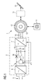
- an electric drive has a motor 1 and a motor connection 2 (motor control circuit 2).
- the engine 1 may be formed as needed.
- the engine 1 as a permanent-magnet synchronous machine be educated.
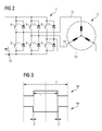
- the engine 1 is as shown in FIG FIG. 2 designed as a brushless DC motor, in particular as a multi-phase brushless DC motor.
- the engine 1 as required as indoor or - as shown in FIG. 1 - Be designed as an external rotor motor.
- the motor interface 2 serves to supply the motor 1 with electrical energy and to control the motor 1.
- the motor interface 2 has a DC voltage circuit 3.
- the DC voltage circuit 3 is - inter alia - a support capacitor 4 is arranged.
- the DC voltage circuit 3 is connected to the supply capacitor 5 for feeding energy into the backup capacitor 4.
- a rectifier 6 may be present, which connects the DC voltage circuit 3 with the single-phase or three-phase public voltage network (rated voltage in the single-phase case 100 V, 110 V or 230 V, mains frequency 50 Hz or 60 Hz).
- the single-phase or three-phase public voltage network rated voltage in the single-phase case 100 V, 110 V or 230 V, mains frequency 50 Hz or 60 Hz.
- 24 V DC possibly even low voltages below 24 V.
- the engine interface 2 also has a switching device 7. About the switching device 7, the motor 1 to the backup capacitor 4 can be connected.
- the switching device 7 has according to this purpose FIG. 2 Switching elements 8, 9 on.
- the engine 1 is usually designed as a multi-phase motor.
- the switching elements 8, 9 of the switching device 7 for each phase 10 of the motor 1 each have an upper switching element 8 and a lower switching element 9.
- the respective phase 10 of the motor 1 to an upper potential of the backup capacitor 4 can be connected ,
- the respective phase 10 can be connected via the respective lower switching element 9 to a lower potential of the backup capacitor 4.
- the switching elements 8, 9 are generally designed as semiconductor switching elements, for example as MOSFETs or as IGBTs. They have intrinsic freewheeling diodes 11.
- the freewheeling diodes 11 are manufacturing technology unavoidable. It is in the freewheeling diodes 11 so not from the switching elements 8, 9 separate components that could be omitted in principle, but they are unavoidable in any case exist.
- the engine 1 has according to FIG. 1 a stator 12 and a rotor 13.
- the rotor 13 is rotatably supported relative to the stator 12.
- a voltage U present on the support capacitor 4 referred to below as the intermediate circuit voltage U
- a corresponding moment can therefore be exerted on the rotor 13, so that the rotor 13 is rotated.
- the rotor 13 is connected to a spring device 14.
- the spring device 14 is relaxed and relaxed during rotation of the rotor 13.
- the spring device 14 has a state in which it is (completely) relaxed or not completely relaxed, but - for example, due to a stop - no longer exerts a restoring force on the rotor 13.
- the corresponding position of the rotor 13 corresponds to a rest position of the rotor 13.
- the rotor 13 is acted upon by the spring means 14 with a restoring force, ie with a force which drives the rotor 13 back to the rest position.
- the rotor 13 can, for example - be it directly, be it via an in FIG. 1 dashed lines indicated gear 15 - be connected to a flap 16 or a valve 16.
- the engine interface 2 has according to FIG. 1 Furthermore, a control device 17 for the engine 1.
- the control device 17 serves to control the switching device 7, in particular the switching elements 8, 9. It is supplied via the backup capacitor 4 with electrical energy.
- the control device 17 is thus arranged either between the support capacitor 4 and the switching device 7 or according to the representation of FIG. 1 Although preceded by the support capacitor 4, in the latter case, no decoupling of the control device 17 from the backup capacitor 4 by a correspondingly arranged decoupling diode 18 takes place.
- the decoupling diode 18 is therefore in FIG. 1 only dashed lines and crossed out.
- control device 17 controls the switching elements 8, 9 of the switching device 7.
- the control takes place as a function of a desired deflection x * of the rotor 13.
- the desired deflection x * is the control device 17 in normal operation according to FIG. 1 predetermined from the outside, for example via an input device, not shown, by a human or by a higher-level control device, also not shown.
- the control device 17 controls the switching elements 8, 9 such that an actual deflection of the rotor 13 of the desired deflection x * is tracked.
- the corresponding control of the switching elements 8, 9 of the switching device 7 is well known to those skilled in the art.
- the control device 17 controls the upper and the lower switching elements 8, 9 in the rule pulse width modulated and above all in push-pull. Relative to any of the phases 10 is thus - see FIG. 3 - An activation in clock cycles T, wherein within the respective clock cycle T during a turn-on period T 'of the respective phase 10, the respective upper switching element 8 is controlled to be "conductive".
- the corresponding lower switching element 9 is controlled to "disabled" during the turn-on period T '.
- the control device 17 must ensure by appropriate control of the switching device 7 that critical operating states of the drive can be avoided.
- the controller 17 is thus configured - for example programmed - to use the following in connection with FIG. 4 explained mode of operation realized:
- step S1 the control device 17 checks whether the power supply of the DC voltage circuit 3 from the supply network 5 takes place. Depending on the result of the check, the control device 17 proceeds to a step S2 or to a step S4.
- step S2 the control device 17 receives the desired deflection x * of the rotor 13.
- step S3 the control device 17 controls the switching elements 8, 9 of the switching device 7, so that the actual deflection of the rotor 13 of the target deflection x * is tracked.
- the tracking of the actual displacement can, for example, be speed-controlled, speed-limited or torque-limited.
- the corresponding control schemes and the corresponding determination of the drive schemes for the switching elements 8, 9 of the switching device 7 are known to those skilled in the art.
- step S4 the control device 17 automatically sets the desired deflection x * to the rest position. Furthermore, the control device 17 controls the switching elements 8, 9 of the switching device 7 in a step S5 such that the motor 1 via the switching elements 8, 9 of the switching device 7 feeds energy into the backup capacitor 4. Therefore, the control device 17 controls in particular in emergency mode, the upper and lower switching elements 8, 9 in phases in push-pull.
- step S5 The exact nature of the transfer of the rotor 13 in the rest position may be determined as needed in the context of step S5.
- the control device 17 analogous to step S3, the switching elements 8, 9 of the switching device 7 to control such that the rotor 13 is speed-controlled or speed-limited process in the rest position.
- the energy fed into the backup capacitor 4 initially increases the intermediate circuit voltage U in emergency operation.
- the control device 17 since the control device 17 is supplied with electrical energy via the backup capacitor 4, ie to the same extent as in normal operation, the control device 17 acts by its power consumption an excessive increase of the intermediate circuit voltage U opposite.
- step S5 The manner in which the corresponding drive signals for the switching elements 8, 9 must be determined in the context of step S5 is known to those skilled in the art.
- the control device 17 can determine the control signals for the switching elements 8, 9 in the same way as in normal operation, when there the target deflection x * is set from the outside to the rest position. Under certain circumstances, therefore, the step S5 even completely eliminated. In this case, from step S5 to step S3.
- FIG. 5 are - in addition to the steps S1 to S5 - further steps S6 to S8 available.
- step S6 the controller 17 determines an energy state EZ of the DC circuit 3. Due to the fact that the step S6 is followed by the step S5, the step S6 is carried out at a time to which the motor 1 via the switching device 7 energy in the backup capacitor 4 is fed.
- the control device 17 for example via a correspondingly arranged current measuring device 19 (see FIG. 2 ) detect the current I fed by the switching device 7 into the DC voltage circuit 3.
- the control device 17 via a correspondingly arranged current measuring device 19 '(see FIG. 1 ) detect the current I 'fed to the backup capacitor 4 itself.
- the control device 17 according to FIG. 1 detect the voltage present on the backup capacitor 4 DC link voltage U.
- step S7 the control device 17 checks whether the determined energy state EZ of the DC voltage circuit 3 is above a minimum energy Emin. Depending on the result of the check, the control device 17 either transfers to step S1 or to step S8. If the control device 17 proceeds to step S8, it blocks all the switching elements 8, 9 of the switching device 7 in step S8.
- the embodiment according to FIG. 5 thus causes that in emergency operation only at the beginning of the return of the rotor 13 electrical energy is fed into the backup capacitor 4.
- the control device 17 sets the control of the switching elements 8, 9.
- the present invention has significant advantages.
- the switching elements 8, 9 and also the support capacitor 4 can be made smaller than in the prior art.
- an overload of the freewheeling diodes 11 is excluded.
- mechanical stresses on the motor 1, the gear 15 and the flap 16 and the valve 16 can be avoided.
Landscapes
- Engineering & Computer Science (AREA)
- Power Engineering (AREA)
- Business, Economics & Management (AREA)
- Emergency Management (AREA)
- Control Of Motors That Do Not Use Commutators (AREA)
Priority Applications (3)
| Application Number | Priority Date | Filing Date | Title |
|---|---|---|---|
| EP11182832.3A EP2573640B1 (fr) | 2011-09-26 | 2011-09-26 | Entraînement à ressort doté d'une récupération active dans le circuit de tension continue |
| US13/624,746 US8704465B2 (en) | 2011-09-26 | 2012-09-21 | Spring-loaded drive with active feedback in DC circuit |
| CN201210363039.0A CN103023403B (zh) | 2011-09-26 | 2012-09-26 | 直流电路中的具有主动反馈的弹簧式驱动器 |
Applications Claiming Priority (1)
| Application Number | Priority Date | Filing Date | Title |
|---|---|---|---|
| EP11182832.3A EP2573640B1 (fr) | 2011-09-26 | 2011-09-26 | Entraînement à ressort doté d'une récupération active dans le circuit de tension continue |
Publications (2)
| Publication Number | Publication Date |
|---|---|
| EP2573640A1 true EP2573640A1 (fr) | 2013-03-27 |
| EP2573640B1 EP2573640B1 (fr) | 2014-06-18 |
Family
ID=44720696
Family Applications (1)
| Application Number | Title | Priority Date | Filing Date |
|---|---|---|---|
| EP11182832.3A Active EP2573640B1 (fr) | 2011-09-26 | 2011-09-26 | Entraînement à ressort doté d'une récupération active dans le circuit de tension continue |
Country Status (3)
| Country | Link |
|---|---|
| US (1) | US8704465B2 (fr) |
| EP (1) | EP2573640B1 (fr) |
| CN (1) | CN103023403B (fr) |
Cited By (5)
| Publication number | Priority date | Publication date | Assignee | Title |
|---|---|---|---|---|
| US8704465B2 (en) | 2011-09-26 | 2014-04-22 | Siemens Aktiengesellschaft | Spring-loaded drive with active feedback in DC circuit |
| EP3104518A1 (fr) * | 2015-06-10 | 2016-12-14 | Belimo Holding AG | Circuit de commande pour un entrainement de securite |
| WO2017153001A1 (fr) * | 2016-03-11 | 2017-09-14 | Karl Dungs Gmbh & Co. Kg | Servomoteur de vanne |
| CN108431386A (zh) * | 2016-01-05 | 2018-08-21 | 斯堪尼亚商用车有限公司 | 弹簧复位节气门致动器、其控制方法和节气门组件 |
| WO2023165713A1 (fr) * | 2022-03-04 | 2023-09-07 | Pierburg Gmbh | Procédé de commande d'un actionneur électromécanique dans un mode de maintien dynamique |
Families Citing this family (1)
| Publication number | Priority date | Publication date | Assignee | Title |
|---|---|---|---|---|
| DE102017117399A1 (de) * | 2017-08-01 | 2019-02-07 | Knorr-Bremse Systeme für Schienenfahrzeuge GmbH | Hydraulisches Bremssystem mit elektronischer Regeleinheit sowie Verfahren zum Betrieb desselben |
Citations (8)
| Publication number | Priority date | Publication date | Assignee | Title |
|---|---|---|---|---|
| JPH01165974A (ja) * | 1987-12-23 | 1989-06-29 | Hitachi Ltd | 電力変換装置 |
| JPH1165679A (ja) * | 1997-08-22 | 1999-03-09 | Yoshihiro Suda | 振動エネルギーを電気的なエネルギーとして蓄え,アクティブ制御を行う防振装置 |
| WO2005119898A2 (fr) | 2004-06-04 | 2005-12-15 | Belimo Holding Ag | Moteur a courant continu sans balais |
| EP1655165A2 (fr) * | 2004-11-08 | 2006-05-10 | Toyota Jidosha Kabushiki Kaisha | Dispositif de propulsion et véhicule équipé d'un tel dispositif |
| DE102005031514A1 (de) * | 2005-07-06 | 2007-01-11 | Zf Friedrichshafen Ag | Vorrichtung zur Spannungsversorgung von elektrischen Verbrauchern in Kraftfahrzeugen |
| US20100007301A1 (en) * | 2006-05-24 | 2010-01-14 | Belimo Holding Ag | Safety drive for a flap or a valve |
| AT507558A4 (de) * | 2009-01-22 | 2010-06-15 | Starlinger & Co Gmbh | Vorrichtung zum regeln der schussbändchenspannung an einem webschützen, damit ausgestattete webschützen und rundwebmaschine |
| DE102009007562A1 (de) * | 2009-02-04 | 2010-08-12 | Sew-Eurodrive Gmbh & Co. Kg | Fahrzeug und Verfahren zum Betreiben eines Fahrzeuges |
Family Cites Families (8)
| Publication number | Priority date | Publication date | Assignee | Title |
|---|---|---|---|---|
| US6100655A (en) * | 1999-02-19 | 2000-08-08 | Mcintosh; Douglas S. | Mechanical return fail-safe actuator for damper, valve, elevator or other positioning device |
| JP4347982B2 (ja) * | 2000-02-28 | 2009-10-21 | 三菱電機株式会社 | エレベーターの制御装置 |
| CN1240607C (zh) * | 2002-12-04 | 2006-02-08 | 上海振华港口机械(集团)股份有限公司 | 利用超级电容的轮胎式龙门集装箱起重机 |
| CN100521499C (zh) * | 2004-06-04 | 2009-07-29 | 贝利莫控股公司 | 无刷直流电机 |
| US7425807B1 (en) * | 2006-11-29 | 2008-09-16 | Active Power, Inc. | Transient energy systems and methods for use of the same |
| US20080221876A1 (en) | 2007-03-08 | 2008-09-11 | Universitat Fur Musik Und Darstellende Kunst | Method for processing audio data into a condensed version |
| US8162596B1 (en) * | 2007-04-20 | 2012-04-24 | Ebara International Corp. | Support device for high pressure pumps usable in or on the deck of a marine vessel |
| EP2573640B1 (fr) | 2011-09-26 | 2014-06-18 | Siemens Aktiengesellschaft | Entraînement à ressort doté d'une récupération active dans le circuit de tension continue |
-
2011
- 2011-09-26 EP EP11182832.3A patent/EP2573640B1/fr active Active
-
2012
- 2012-09-21 US US13/624,746 patent/US8704465B2/en active Active
- 2012-09-26 CN CN201210363039.0A patent/CN103023403B/zh active Active
Patent Citations (8)
| Publication number | Priority date | Publication date | Assignee | Title |
|---|---|---|---|---|
| JPH01165974A (ja) * | 1987-12-23 | 1989-06-29 | Hitachi Ltd | 電力変換装置 |
| JPH1165679A (ja) * | 1997-08-22 | 1999-03-09 | Yoshihiro Suda | 振動エネルギーを電気的なエネルギーとして蓄え,アクティブ制御を行う防振装置 |
| WO2005119898A2 (fr) | 2004-06-04 | 2005-12-15 | Belimo Holding Ag | Moteur a courant continu sans balais |
| EP1655165A2 (fr) * | 2004-11-08 | 2006-05-10 | Toyota Jidosha Kabushiki Kaisha | Dispositif de propulsion et véhicule équipé d'un tel dispositif |
| DE102005031514A1 (de) * | 2005-07-06 | 2007-01-11 | Zf Friedrichshafen Ag | Vorrichtung zur Spannungsversorgung von elektrischen Verbrauchern in Kraftfahrzeugen |
| US20100007301A1 (en) * | 2006-05-24 | 2010-01-14 | Belimo Holding Ag | Safety drive for a flap or a valve |
| AT507558A4 (de) * | 2009-01-22 | 2010-06-15 | Starlinger & Co Gmbh | Vorrichtung zum regeln der schussbändchenspannung an einem webschützen, damit ausgestattete webschützen und rundwebmaschine |
| DE102009007562A1 (de) * | 2009-02-04 | 2010-08-12 | Sew-Eurodrive Gmbh & Co. Kg | Fahrzeug und Verfahren zum Betreiben eines Fahrzeuges |
Cited By (8)
| Publication number | Priority date | Publication date | Assignee | Title |
|---|---|---|---|---|
| US8704465B2 (en) | 2011-09-26 | 2014-04-22 | Siemens Aktiengesellschaft | Spring-loaded drive with active feedback in DC circuit |
| EP3104518A1 (fr) * | 2015-06-10 | 2016-12-14 | Belimo Holding AG | Circuit de commande pour un entrainement de securite |
| CN108431386A (zh) * | 2016-01-05 | 2018-08-21 | 斯堪尼亚商用车有限公司 | 弹簧复位节气门致动器、其控制方法和节气门组件 |
| EP3400376A4 (fr) * | 2016-01-05 | 2019-09-11 | Scania CV AB | Actionneur de papillon à rappel par ressort, son procédé de commande et ensemble papillon |
| WO2017153001A1 (fr) * | 2016-03-11 | 2017-09-14 | Karl Dungs Gmbh & Co. Kg | Servomoteur de vanne |
| RU2721827C2 (ru) * | 2016-03-11 | 2020-05-22 | Карл Дунгс Гмбх Унд Ко. Кг | Исполнительный привод клапана |
| US10941874B2 (en) | 2016-03-11 | 2021-03-09 | Karl Dungs Gmbh & Co. Kg | Valve actuating drive |
| WO2023165713A1 (fr) * | 2022-03-04 | 2023-09-07 | Pierburg Gmbh | Procédé de commande d'un actionneur électromécanique dans un mode de maintien dynamique |
Also Published As
| Publication number | Publication date |
|---|---|
| CN103023403B (zh) | 2015-05-20 |
| CN103023403A (zh) | 2013-04-03 |
| US20130076276A1 (en) | 2013-03-28 |
| US8704465B2 (en) | 2014-04-22 |
| EP2573640B1 (fr) | 2014-06-18 |
Similar Documents
| Publication | Publication Date | Title |
|---|---|---|
| EP2573640B1 (fr) | Entraînement à ressort doté d'une récupération active dans le circuit de tension continue | |
| EP2237986B1 (fr) | Procédé de fonctionnement d'un réseau électrique, en particulier d'un véhicule automobile | |
| EP3022836B1 (fr) | Protection contre les surtensions pour redresseurs actifs en cas de délestage brusque | |
| DE102008026549A1 (de) | Schutz für Permanentmagnetmotor-Steuerungsschaltungen | |
| AT504808B1 (de) | Synchronmaschine | |
| WO2011042237A1 (fr) | Procédé pour faire fonctionner un système d'entraînement ainsi que système d'entraînement | |
| EP0935336B2 (fr) | Méthode et dispositif de commande d' un moteur synchron | |
| WO2017101996A1 (fr) | Unité électronique de puissance | |
| EP3460593A1 (fr) | Dispositif de commutation sécurisé | |
| DE102011075789A1 (de) | Verfahren zum Betrieb einer Drehfeldmaschine | |
| EP2244372A2 (fr) | Dispositif de circuit pour une installation éolienne | |
| EP3163733A1 (fr) | Convertisseur pour une machine électrique, dispositif d'entraînement électrique pour un véhicule automobile et procédé de fonctionnement d'un convertisseur | |
| EP1561275B1 (fr) | Systeme de generateur a generateur a couplage direct au reseau et procede pour maitriser des pannes de secteur | |
| DE102017204091A1 (de) | Schaltvorrichtung zum Schalten eines elektrischen Erregerstroms für eine elektrische Maschine mit einem Läufer | |
| WO2013064474A2 (fr) | Procédé et dispositif pour faire fonctionner une machine électrique à commutation électronique en cas de défaillance | |
| DE102013009036A1 (de) | Antriebsvorrichtung | |
| DE102014116689A1 (de) | Vorrichtung und Verfahren zum Sichern einer Antriebssteuerung gegen Versorgungsspannungsausfälle | |
| DE112019001048T5 (de) | Motorantriebssteuervorrichtung und motorantriebssteuerverfahren | |
| DE102018133248A1 (de) | Motorsteuervorrichtung und Steuerverfahren für Motorsteuervorrichtung | |
| DE102013103142A1 (de) | Motorantriebssteuerung | |
| DE102008040724A1 (de) | Schaltvorrichtung zum Begrenzen des Einschaltstroms eines elektrischen Verbrauchers | |
| DE102009001507B4 (de) | Verfahren zum Betrieb eines elektrischen Servolenksystems und danach arbeitendes Steuergerät | |
| EP3449564B1 (fr) | Procédé et dispositif de commande d'une machine électrique | |
| DE102007052233A1 (de) | Vorrichtung zur Energieversorgung von Antrieben | |
| DE102009049623A1 (de) | Verfahren und Vorrichtung zur Regelung der Spannung eines Zwischenkreises eines Kraftfahrzeugs |
Legal Events
| Date | Code | Title | Description |
|---|---|---|---|
| PUAI | Public reference made under article 153(3) epc to a published international application that has entered the european phase |
Free format text: ORIGINAL CODE: 0009012 |
|
| AK | Designated contracting states |
Kind code of ref document: A1 Designated state(s): AL AT BE BG CH CY CZ DE DK EE ES FI FR GB GR HR HU IE IS IT LI LT LU LV MC MK MT NL NO PL PT RO RS SE SI SK SM TR |
|
| AX | Request for extension of the european patent |
Extension state: BA ME |
|
| 17P | Request for examination filed |
Effective date: 20130918 |
|
| RBV | Designated contracting states (corrected) |
Designated state(s): AL AT BE BG CH CY CZ DE DK EE ES FI FR GB GR HR HU IE IS IT LI LT LU LV MC MK MT NL NO PL PT RO RS SE SI SK SM TR |
|
| RIC1 | Information provided on ipc code assigned before grant |
Ipc: H02M 1/32 20070101ALI20131022BHEP Ipc: G05D 19/02 20060101AFI20131022BHEP Ipc: H02P 25/02 20060101ALI20131022BHEP Ipc: H02P 6/24 20060101ALI20131022BHEP Ipc: H02P 27/08 20060101ALI20131022BHEP Ipc: H02J 9/06 20060101ALI20131022BHEP |
|
| GRAP | Despatch of communication of intention to grant a patent |
Free format text: ORIGINAL CODE: EPIDOSNIGR1 |
|
| INTG | Intention to grant announced |
Effective date: 20140107 |
|
| GRAS | Grant fee paid |
Free format text: ORIGINAL CODE: EPIDOSNIGR3 |
|
| GRAA | (expected) grant |
Free format text: ORIGINAL CODE: 0009210 |
|
| AK | Designated contracting states |
Kind code of ref document: B1 Designated state(s): AL AT BE BG CH CY CZ DE DK EE ES FI FR GB GR HR HU IE IS IT LI LT LU LV MC MK MT NL NO PL PT RO RS SE SI SK SM TR |
|
| REG | Reference to a national code |
Ref country code: GB Ref legal event code: FG4D Free format text: NOT ENGLISH |
|
| REG | Reference to a national code |
Ref country code: CH Ref legal event code: EP |
|
| REG | Reference to a national code |
Ref country code: AT Ref legal event code: REF Ref document number: 673684 Country of ref document: AT Kind code of ref document: T Effective date: 20140715 |
|
| REG | Reference to a national code |
Ref country code: IE Ref legal event code: FG4D Free format text: LANGUAGE OF EP DOCUMENT: GERMAN |
|
| REG | Reference to a national code |
Ref country code: DE Ref legal event code: R096 Ref document number: 502011003428 Country of ref document: DE Effective date: 20140731 |
|
| PG25 | Lapsed in a contracting state [announced via postgrant information from national office to epo] |
Ref country code: LT Free format text: LAPSE BECAUSE OF FAILURE TO SUBMIT A TRANSLATION OF THE DESCRIPTION OR TO PAY THE FEE WITHIN THE PRESCRIBED TIME-LIMIT Effective date: 20140618 Ref country code: GR Free format text: LAPSE BECAUSE OF FAILURE TO SUBMIT A TRANSLATION OF THE DESCRIPTION OR TO PAY THE FEE WITHIN THE PRESCRIBED TIME-LIMIT Effective date: 20140919 Ref country code: FI Free format text: LAPSE BECAUSE OF FAILURE TO SUBMIT A TRANSLATION OF THE DESCRIPTION OR TO PAY THE FEE WITHIN THE PRESCRIBED TIME-LIMIT Effective date: 20140618 Ref country code: NO Free format text: LAPSE BECAUSE OF FAILURE TO SUBMIT A TRANSLATION OF THE DESCRIPTION OR TO PAY THE FEE WITHIN THE PRESCRIBED TIME-LIMIT Effective date: 20140918 Ref country code: CY Free format text: LAPSE BECAUSE OF FAILURE TO SUBMIT A TRANSLATION OF THE DESCRIPTION OR TO PAY THE FEE WITHIN THE PRESCRIBED TIME-LIMIT Effective date: 20140618 |
|
| REG | Reference to a national code |
Ref country code: NL Ref legal event code: VDEP Effective date: 20140618 |
|
| REG | Reference to a national code |
Ref country code: LT Ref legal event code: MG4D |
|
| PG25 | Lapsed in a contracting state [announced via postgrant information from national office to epo] |
Ref country code: HR Free format text: LAPSE BECAUSE OF FAILURE TO SUBMIT A TRANSLATION OF THE DESCRIPTION OR TO PAY THE FEE WITHIN THE PRESCRIBED TIME-LIMIT Effective date: 20140618 Ref country code: SE Free format text: LAPSE BECAUSE OF FAILURE TO SUBMIT A TRANSLATION OF THE DESCRIPTION OR TO PAY THE FEE WITHIN THE PRESCRIBED TIME-LIMIT Effective date: 20140618 Ref country code: RS Free format text: LAPSE BECAUSE OF FAILURE TO SUBMIT A TRANSLATION OF THE DESCRIPTION OR TO PAY THE FEE WITHIN THE PRESCRIBED TIME-LIMIT Effective date: 20140618 Ref country code: LV Free format text: LAPSE BECAUSE OF FAILURE TO SUBMIT A TRANSLATION OF THE DESCRIPTION OR TO PAY THE FEE WITHIN THE PRESCRIBED TIME-LIMIT Effective date: 20140618 |
|
| RAP2 | Party data changed (patent owner data changed or rights of a patent transferred) |
Owner name: SIEMENS SCHWEIZ AG |
|
| PG25 | Lapsed in a contracting state [announced via postgrant information from national office to epo] |
Ref country code: PT Free format text: LAPSE BECAUSE OF FAILURE TO SUBMIT A TRANSLATION OF THE DESCRIPTION OR TO PAY THE FEE WITHIN THE PRESCRIBED TIME-LIMIT Effective date: 20141020 Ref country code: EE Free format text: LAPSE BECAUSE OF FAILURE TO SUBMIT A TRANSLATION OF THE DESCRIPTION OR TO PAY THE FEE WITHIN THE PRESCRIBED TIME-LIMIT Effective date: 20140618 Ref country code: SK Free format text: LAPSE BECAUSE OF FAILURE TO SUBMIT A TRANSLATION OF THE DESCRIPTION OR TO PAY THE FEE WITHIN THE PRESCRIBED TIME-LIMIT Effective date: 20140618 Ref country code: RO Free format text: LAPSE BECAUSE OF FAILURE TO SUBMIT A TRANSLATION OF THE DESCRIPTION OR TO PAY THE FEE WITHIN THE PRESCRIBED TIME-LIMIT Effective date: 20140618 Ref country code: CZ Free format text: LAPSE BECAUSE OF FAILURE TO SUBMIT A TRANSLATION OF THE DESCRIPTION OR TO PAY THE FEE WITHIN THE PRESCRIBED TIME-LIMIT Effective date: 20140618 Ref country code: ES Free format text: LAPSE BECAUSE OF FAILURE TO SUBMIT A TRANSLATION OF THE DESCRIPTION OR TO PAY THE FEE WITHIN THE PRESCRIBED TIME-LIMIT Effective date: 20140618 |
|
| PG25 | Lapsed in a contracting state [announced via postgrant information from national office to epo] |
Ref country code: NL Free format text: LAPSE BECAUSE OF FAILURE TO SUBMIT A TRANSLATION OF THE DESCRIPTION OR TO PAY THE FEE WITHIN THE PRESCRIBED TIME-LIMIT Effective date: 20140618 Ref country code: IS Free format text: LAPSE BECAUSE OF FAILURE TO SUBMIT A TRANSLATION OF THE DESCRIPTION OR TO PAY THE FEE WITHIN THE PRESCRIBED TIME-LIMIT Effective date: 20141018 Ref country code: PL Free format text: LAPSE BECAUSE OF FAILURE TO SUBMIT A TRANSLATION OF THE DESCRIPTION OR TO PAY THE FEE WITHIN THE PRESCRIBED TIME-LIMIT Effective date: 20140618 |
|
| REG | Reference to a national code |
Ref country code: DE Ref legal event code: R097 Ref document number: 502011003428 Country of ref document: DE |
|
| PLBE | No opposition filed within time limit |
Free format text: ORIGINAL CODE: 0009261 |
|
| STAA | Information on the status of an ep patent application or granted ep patent |
Free format text: STATUS: NO OPPOSITION FILED WITHIN TIME LIMIT |
|
| PG25 | Lapsed in a contracting state [announced via postgrant information from national office to epo] |
Ref country code: DK Free format text: LAPSE BECAUSE OF FAILURE TO SUBMIT A TRANSLATION OF THE DESCRIPTION OR TO PAY THE FEE WITHIN THE PRESCRIBED TIME-LIMIT Effective date: 20140618 Ref country code: LU Free format text: LAPSE BECAUSE OF FAILURE TO SUBMIT A TRANSLATION OF THE DESCRIPTION OR TO PAY THE FEE WITHIN THE PRESCRIBED TIME-LIMIT Effective date: 20140926 Ref country code: MC Free format text: LAPSE BECAUSE OF FAILURE TO SUBMIT A TRANSLATION OF THE DESCRIPTION OR TO PAY THE FEE WITHIN THE PRESCRIBED TIME-LIMIT Effective date: 20140618 Ref country code: IT Free format text: LAPSE BECAUSE OF FAILURE TO SUBMIT A TRANSLATION OF THE DESCRIPTION OR TO PAY THE FEE WITHIN THE PRESCRIBED TIME-LIMIT Effective date: 20140618 |
|
| REG | Reference to a national code |
Ref country code: CH Ref legal event code: PL |
|
| REG | Reference to a national code |
Ref country code: DE Ref legal event code: R081 Ref document number: 502011003428 Country of ref document: DE Owner name: SIEMENS SCHWEIZ AG, CH Free format text: FORMER OWNER: SIEMENS AKTIENGESELLSCHAFT, 80333 MUENCHEN, DE Effective date: 20150407 |
|
| 26N | No opposition filed |
Effective date: 20150319 |
|
| REG | Reference to a national code |
Ref country code: IE Ref legal event code: MM4A |
|
| REG | Reference to a national code |
Ref country code: FR Ref legal event code: ST Effective date: 20150529 |
|
| PG25 | Lapsed in a contracting state [announced via postgrant information from national office to epo] |
Ref country code: BE Free format text: LAPSE BECAUSE OF NON-PAYMENT OF DUE FEES Effective date: 20140930 |
|
| PG25 | Lapsed in a contracting state [announced via postgrant information from national office to epo] |
Ref country code: SI Free format text: LAPSE BECAUSE OF FAILURE TO SUBMIT A TRANSLATION OF THE DESCRIPTION OR TO PAY THE FEE WITHIN THE PRESCRIBED TIME-LIMIT Effective date: 20140618 Ref country code: CH Free format text: LAPSE BECAUSE OF NON-PAYMENT OF DUE FEES Effective date: 20140930 Ref country code: LI Free format text: LAPSE BECAUSE OF NON-PAYMENT OF DUE FEES Effective date: 20140930 |
|
| PG25 | Lapsed in a contracting state [announced via postgrant information from national office to epo] |
Ref country code: FR Free format text: LAPSE BECAUSE OF NON-PAYMENT OF DUE FEES Effective date: 20140930 Ref country code: IE Free format text: LAPSE BECAUSE OF NON-PAYMENT OF DUE FEES Effective date: 20140926 |
|
| PG25 | Lapsed in a contracting state [announced via postgrant information from national office to epo] |
Ref country code: SM Free format text: LAPSE BECAUSE OF FAILURE TO SUBMIT A TRANSLATION OF THE DESCRIPTION OR TO PAY THE FEE WITHIN THE PRESCRIBED TIME-LIMIT Effective date: 20140618 |
|
| GBPC | Gb: european patent ceased through non-payment of renewal fee |
Effective date: 20150926 |
|
| PG25 | Lapsed in a contracting state [announced via postgrant information from national office to epo] |
Ref country code: BG Free format text: LAPSE BECAUSE OF FAILURE TO SUBMIT A TRANSLATION OF THE DESCRIPTION OR TO PAY THE FEE WITHIN THE PRESCRIBED TIME-LIMIT Effective date: 20140618 Ref country code: MT Free format text: LAPSE BECAUSE OF FAILURE TO SUBMIT A TRANSLATION OF THE DESCRIPTION OR TO PAY THE FEE WITHIN THE PRESCRIBED TIME-LIMIT Effective date: 20140618 |
|
| PG25 | Lapsed in a contracting state [announced via postgrant information from national office to epo] |
Ref country code: TR Free format text: LAPSE BECAUSE OF FAILURE TO SUBMIT A TRANSLATION OF THE DESCRIPTION OR TO PAY THE FEE WITHIN THE PRESCRIBED TIME-LIMIT Effective date: 20140618 Ref country code: GB Free format text: LAPSE BECAUSE OF NON-PAYMENT OF DUE FEES Effective date: 20150926 Ref country code: HU Free format text: LAPSE BECAUSE OF FAILURE TO SUBMIT A TRANSLATION OF THE DESCRIPTION OR TO PAY THE FEE WITHIN THE PRESCRIBED TIME-LIMIT; INVALID AB INITIO Effective date: 20110926 |
|
| REG | Reference to a national code |
Ref country code: AT Ref legal event code: MM01 Ref document number: 673684 Country of ref document: AT Kind code of ref document: T Effective date: 20160926 |
|
| PG25 | Lapsed in a contracting state [announced via postgrant information from national office to epo] |
Ref country code: AT Free format text: LAPSE BECAUSE OF NON-PAYMENT OF DUE FEES Effective date: 20160926 |
|
| PG25 | Lapsed in a contracting state [announced via postgrant information from national office to epo] |
Ref country code: MK Free format text: LAPSE BECAUSE OF FAILURE TO SUBMIT A TRANSLATION OF THE DESCRIPTION OR TO PAY THE FEE WITHIN THE PRESCRIBED TIME-LIMIT Effective date: 20140618 |
|
| PG25 | Lapsed in a contracting state [announced via postgrant information from national office to epo] |
Ref country code: AL Free format text: LAPSE BECAUSE OF FAILURE TO SUBMIT A TRANSLATION OF THE DESCRIPTION OR TO PAY THE FEE WITHIN THE PRESCRIBED TIME-LIMIT Effective date: 20140618 |
|
| P01 | Opt-out of the competence of the unified patent court (upc) registered |
Effective date: 20230523 |
|
| PGFP | Annual fee paid to national office [announced via postgrant information from national office to epo] |
Ref country code: DE Payment date: 20231120 Year of fee payment: 13 |