EP2573640A1 - Spring-loaded drive with active recovery in direct current circuit - Google Patents
Spring-loaded drive with active recovery in direct current circuit Download PDFInfo
- Publication number
- EP2573640A1 EP2573640A1 EP11182832A EP11182832A EP2573640A1 EP 2573640 A1 EP2573640 A1 EP 2573640A1 EP 11182832 A EP11182832 A EP 11182832A EP 11182832 A EP11182832 A EP 11182832A EP 2573640 A1 EP2573640 A1 EP 2573640A1
- Authority
- EP
- European Patent Office
- Prior art keywords
- motor
- energy
- rotor
- control device
- switching
- Prior art date
- Legal status (The legal status is an assumption and is not a legal conclusion. Google has not performed a legal analysis and makes no representation as to the accuracy of the status listed.)
- Granted
Links
- 238000011084 recovery Methods 0.000 title description 2
- 239000003990 capacitor Substances 0.000 claims abstract description 55
- 238000006073 displacement reaction Methods 0.000 claims description 3
- 230000004044 response Effects 0.000 claims description 2
- 230000007423 decrease Effects 0.000 claims 1
- 230000000284 resting effect Effects 0.000 claims 1
- 239000004065 semiconductor Substances 0.000 abstract description 2
- 230000003213 activating effect Effects 0.000 abstract 1
- 238000000034 method Methods 0.000 description 3
- 230000004913 activation Effects 0.000 description 1
- 230000005540 biological transmission Effects 0.000 description 1
- 230000008859 change Effects 0.000 description 1
- 230000001419 dependent effect Effects 0.000 description 1
- 238000010586 diagram Methods 0.000 description 1
- 230000000694 effects Effects 0.000 description 1
- 238000005516 engineering process Methods 0.000 description 1
- 239000002655 kraft paper Substances 0.000 description 1
- 238000004519 manufacturing process Methods 0.000 description 1
- 230000008569 process Effects 0.000 description 1
- 230000001360 synchronised effect Effects 0.000 description 1
- 230000001960 triggered effect Effects 0.000 description 1
- 238000004804 winding Methods 0.000 description 1
Images


Classifications
-
- H—ELECTRICITY
- H02—GENERATION; CONVERSION OR DISTRIBUTION OF ELECTRIC POWER
- H02J—CIRCUIT ARRANGEMENTS OR SYSTEMS FOR SUPPLYING OR DISTRIBUTING ELECTRIC POWER; SYSTEMS FOR STORING ELECTRIC ENERGY
- H02J9/00—Circuit arrangements for emergency or stand-by power supply, e.g. for emergency lighting
- H02J9/04—Circuit arrangements for emergency or stand-by power supply, e.g. for emergency lighting in which the distribution system is disconnected from the normal source and connected to a standby source
- H02J9/06—Circuit arrangements for emergency or stand-by power supply, e.g. for emergency lighting in which the distribution system is disconnected from the normal source and connected to a standby source with automatic change-over, e.g. UPS systems
- H02J9/062—Circuit arrangements for emergency or stand-by power supply, e.g. for emergency lighting in which the distribution system is disconnected from the normal source and connected to a standby source with automatic change-over, e.g. UPS systems for AC powered loads
-
- H—ELECTRICITY
- H02—GENERATION; CONVERSION OR DISTRIBUTION OF ELECTRIC POWER
- H02P—CONTROL OR REGULATION OF ELECTRIC MOTORS, ELECTRIC GENERATORS OR DYNAMO-ELECTRIC CONVERTERS; CONTROLLING TRANSFORMERS, REACTORS OR CHOKE COILS
- H02P25/00—Arrangements or methods for the control of AC motors characterised by the kind of AC motor or by structural details
- H02P25/02—Arrangements or methods for the control of AC motors characterised by the kind of AC motor or by structural details characterised by the kind of motor
- H02P25/032—Reciprocating, oscillating or vibrating motors
-
- H—ELECTRICITY
- H02—GENERATION; CONVERSION OR DISTRIBUTION OF ELECTRIC POWER
- H02P—CONTROL OR REGULATION OF ELECTRIC MOTORS, ELECTRIC GENERATORS OR DYNAMO-ELECTRIC CONVERTERS; CONTROLLING TRANSFORMERS, REACTORS OR CHOKE COILS
- H02P3/00—Arrangements for stopping or slowing electric motors, generators, or dynamo-electric converters
- H02P3/06—Arrangements for stopping or slowing electric motors, generators, or dynamo-electric converters for stopping or slowing an individual dynamo-electric motor or dynamo-electric converter
- H02P3/18—Arrangements for stopping or slowing electric motors, generators, or dynamo-electric converters for stopping or slowing an individual dynamo-electric motor or dynamo-electric converter for stopping or slowing an ac motor
-
- H—ELECTRICITY
- H02—GENERATION; CONVERSION OR DISTRIBUTION OF ELECTRIC POWER
- H02P—CONTROL OR REGULATION OF ELECTRIC MOTORS, ELECTRIC GENERATORS OR DYNAMO-ELECTRIC CONVERTERS; CONTROLLING TRANSFORMERS, REACTORS OR CHOKE COILS
- H02P6/00—Arrangements for controlling synchronous motors or other dynamo-electric motors using electronic commutation dependent on the rotor position; Electronic commutators therefor
- H02P6/24—Arrangements for stopping
-
- H—ELECTRICITY
- H02—GENERATION; CONVERSION OR DISTRIBUTION OF ELECTRIC POWER
- H02M—APPARATUS FOR CONVERSION BETWEEN AC AND AC, BETWEEN AC AND DC, OR BETWEEN DC AND DC, AND FOR USE WITH MAINS OR SIMILAR POWER SUPPLY SYSTEMS; CONVERSION OF DC OR AC INPUT POWER INTO SURGE OUTPUT POWER; CONTROL OR REGULATION THEREOF
- H02M1/00—Details of apparatus for conversion
- H02M1/0096—Means for increasing hold-up time, i.e. the duration of time that a converter's output will remain within regulated limits following a loss of input power
Definitions
- Spring loaded actuators are often used as actuators for valves and dampers to ensure that the Valve or the flap is transferred in case of failure of the supply network in a defined position.
- the motor is designed as a brushless DC motor.
- the WO 2005/119 898 A2 In order to avoid the above-mentioned problems, it is proposed to short pulse width modulated two of three windings of the motor by means of the converter and thereby to transfer the rotor to its rest position with limited speed.
- the object of the present invention is therefore to develop an electric drive of the above-mentioned type such that the problems of the prior art are completely eliminated.
- the control device Due to the supply of power to the control device via the backup capacitor, the control device is connected as a consumer to the backup capacitor. The control device therefore counteracts by their power consumption too large a voltage increase on the backup capacitor. Due to the driving of the switching elements of the switching device, the fed-back current via the switching elements of the switching device itself - in contrast to intrinsically existing, only to a small extent current carrying freewheeling diodes of the switching elements - flow. As a result, the switching device is electrically relieved. Due to the continued operation of the control device and the now given deviation of the actual deflection of the rotor from the - newly set - target deflection is essentially a braked transfer of the rotor in the rest position, as in normal operation also.
- control device controls the switching elements of the switching device in the event that the supply of energy from the supply network fails in the deflected state of the rotor, that the rotor speed-controlled or limited speed is moved into the rest position.
- the engine can be designed in particular as a multi-phase motor.
- the switching elements of the switching device usually comprise upper and lower switching elements, wherein each phase of the motor is connectable via a respective upper switching element to an upper potential of the backup capacitor and via a respective lower switching element to a lower potential of the backup capacitor.
- the respective upper and the respective lower switching element are driven by the control device in push-pull for each phase. According to the invention, this type of control is maintained even in the event that in the deflected state of the rotor, the supply of energy from the mains fails.
- the control device determines in the event that the supply of energy has failed from the supply network in the deflected state of the rotor, during the feeding of energy into the backup capacitor, an energy state of the DC voltage circuit. She is able to do so
- the control device can detect, for example, a current that is fed into the DC voltage circuit or the backup capacitor via the switching device.
- the control device for detecting the energy state of the DC voltage circuit can detect a voltage present at the backup capacitor.
- the drive often serves as a valve or damper drive.
- the rotor is connected directly or via a transmission with a flap or a valve.
- the motor can be designed in particular as a brushless DC motor.
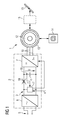
- an electric drive has a motor 1 and a motor connection 2 (motor control circuit 2).
- the engine 1 may be formed as needed.
- the engine 1 as a permanent-magnet synchronous machine be educated.
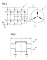
- the engine 1 is as shown in FIG FIG. 2 designed as a brushless DC motor, in particular as a multi-phase brushless DC motor.
- the engine 1 as required as indoor or - as shown in FIG. 1 - Be designed as an external rotor motor.
- the motor interface 2 serves to supply the motor 1 with electrical energy and to control the motor 1.
- the motor interface 2 has a DC voltage circuit 3.
- the DC voltage circuit 3 is - inter alia - a support capacitor 4 is arranged.
- the DC voltage circuit 3 is connected to the supply capacitor 5 for feeding energy into the backup capacitor 4.
- a rectifier 6 may be present, which connects the DC voltage circuit 3 with the single-phase or three-phase public voltage network (rated voltage in the single-phase case 100 V, 110 V or 230 V, mains frequency 50 Hz or 60 Hz).
- the single-phase or three-phase public voltage network rated voltage in the single-phase case 100 V, 110 V or 230 V, mains frequency 50 Hz or 60 Hz.
- 24 V DC possibly even low voltages below 24 V.
- the engine interface 2 also has a switching device 7. About the switching device 7, the motor 1 to the backup capacitor 4 can be connected.
- the switching device 7 has according to this purpose FIG. 2 Switching elements 8, 9 on.
- the engine 1 is usually designed as a multi-phase motor.
- the switching elements 8, 9 of the switching device 7 for each phase 10 of the motor 1 each have an upper switching element 8 and a lower switching element 9.
- the respective phase 10 of the motor 1 to an upper potential of the backup capacitor 4 can be connected ,
- the respective phase 10 can be connected via the respective lower switching element 9 to a lower potential of the backup capacitor 4.
- the switching elements 8, 9 are generally designed as semiconductor switching elements, for example as MOSFETs or as IGBTs. They have intrinsic freewheeling diodes 11.
- the freewheeling diodes 11 are manufacturing technology unavoidable. It is in the freewheeling diodes 11 so not from the switching elements 8, 9 separate components that could be omitted in principle, but they are unavoidable in any case exist.
- the engine 1 has according to FIG. 1 a stator 12 and a rotor 13.
- the rotor 13 is rotatably supported relative to the stator 12.
- a voltage U present on the support capacitor 4 referred to below as the intermediate circuit voltage U
- a corresponding moment can therefore be exerted on the rotor 13, so that the rotor 13 is rotated.
- the rotor 13 is connected to a spring device 14.
- the spring device 14 is relaxed and relaxed during rotation of the rotor 13.
- the spring device 14 has a state in which it is (completely) relaxed or not completely relaxed, but - for example, due to a stop - no longer exerts a restoring force on the rotor 13.
- the corresponding position of the rotor 13 corresponds to a rest position of the rotor 13.
- the rotor 13 is acted upon by the spring means 14 with a restoring force, ie with a force which drives the rotor 13 back to the rest position.
- the rotor 13 can, for example - be it directly, be it via an in FIG. 1 dashed lines indicated gear 15 - be connected to a flap 16 or a valve 16.
- the engine interface 2 has according to FIG. 1 Furthermore, a control device 17 for the engine 1.
- the control device 17 serves to control the switching device 7, in particular the switching elements 8, 9. It is supplied via the backup capacitor 4 with electrical energy.
- the control device 17 is thus arranged either between the support capacitor 4 and the switching device 7 or according to the representation of FIG. 1 Although preceded by the support capacitor 4, in the latter case, no decoupling of the control device 17 from the backup capacitor 4 by a correspondingly arranged decoupling diode 18 takes place.
- the decoupling diode 18 is therefore in FIG. 1 only dashed lines and crossed out.
- control device 17 controls the switching elements 8, 9 of the switching device 7.
- the control takes place as a function of a desired deflection x * of the rotor 13.
- the desired deflection x * is the control device 17 in normal operation according to FIG. 1 predetermined from the outside, for example via an input device, not shown, by a human or by a higher-level control device, also not shown.
- the control device 17 controls the switching elements 8, 9 such that an actual deflection of the rotor 13 of the desired deflection x * is tracked.
- the corresponding control of the switching elements 8, 9 of the switching device 7 is well known to those skilled in the art.
- the control device 17 controls the upper and the lower switching elements 8, 9 in the rule pulse width modulated and above all in push-pull. Relative to any of the phases 10 is thus - see FIG. 3 - An activation in clock cycles T, wherein within the respective clock cycle T during a turn-on period T 'of the respective phase 10, the respective upper switching element 8 is controlled to be "conductive".
- the corresponding lower switching element 9 is controlled to "disabled" during the turn-on period T '.
- the control device 17 must ensure by appropriate control of the switching device 7 that critical operating states of the drive can be avoided.
- the controller 17 is thus configured - for example programmed - to use the following in connection with FIG. 4 explained mode of operation realized:
- step S1 the control device 17 checks whether the power supply of the DC voltage circuit 3 from the supply network 5 takes place. Depending on the result of the check, the control device 17 proceeds to a step S2 or to a step S4.
- step S2 the control device 17 receives the desired deflection x * of the rotor 13.
- step S3 the control device 17 controls the switching elements 8, 9 of the switching device 7, so that the actual deflection of the rotor 13 of the target deflection x * is tracked.
- the tracking of the actual displacement can, for example, be speed-controlled, speed-limited or torque-limited.
- the corresponding control schemes and the corresponding determination of the drive schemes for the switching elements 8, 9 of the switching device 7 are known to those skilled in the art.
- step S4 the control device 17 automatically sets the desired deflection x * to the rest position. Furthermore, the control device 17 controls the switching elements 8, 9 of the switching device 7 in a step S5 such that the motor 1 via the switching elements 8, 9 of the switching device 7 feeds energy into the backup capacitor 4. Therefore, the control device 17 controls in particular in emergency mode, the upper and lower switching elements 8, 9 in phases in push-pull.
- step S5 The exact nature of the transfer of the rotor 13 in the rest position may be determined as needed in the context of step S5.
- the control device 17 analogous to step S3, the switching elements 8, 9 of the switching device 7 to control such that the rotor 13 is speed-controlled or speed-limited process in the rest position.
- the energy fed into the backup capacitor 4 initially increases the intermediate circuit voltage U in emergency operation.
- the control device 17 since the control device 17 is supplied with electrical energy via the backup capacitor 4, ie to the same extent as in normal operation, the control device 17 acts by its power consumption an excessive increase of the intermediate circuit voltage U opposite.
- step S5 The manner in which the corresponding drive signals for the switching elements 8, 9 must be determined in the context of step S5 is known to those skilled in the art.
- the control device 17 can determine the control signals for the switching elements 8, 9 in the same way as in normal operation, when there the target deflection x * is set from the outside to the rest position. Under certain circumstances, therefore, the step S5 even completely eliminated. In this case, from step S5 to step S3.
- FIG. 5 are - in addition to the steps S1 to S5 - further steps S6 to S8 available.
- step S6 the controller 17 determines an energy state EZ of the DC circuit 3. Due to the fact that the step S6 is followed by the step S5, the step S6 is carried out at a time to which the motor 1 via the switching device 7 energy in the backup capacitor 4 is fed.
- the control device 17 for example via a correspondingly arranged current measuring device 19 (see FIG. 2 ) detect the current I fed by the switching device 7 into the DC voltage circuit 3.
- the control device 17 via a correspondingly arranged current measuring device 19 '(see FIG. 1 ) detect the current I 'fed to the backup capacitor 4 itself.
- the control device 17 according to FIG. 1 detect the voltage present on the backup capacitor 4 DC link voltage U.
- step S7 the control device 17 checks whether the determined energy state EZ of the DC voltage circuit 3 is above a minimum energy Emin. Depending on the result of the check, the control device 17 either transfers to step S1 or to step S8. If the control device 17 proceeds to step S8, it blocks all the switching elements 8, 9 of the switching device 7 in step S8.
- the embodiment according to FIG. 5 thus causes that in emergency operation only at the beginning of the return of the rotor 13 electrical energy is fed into the backup capacitor 4.
- the control device 17 sets the control of the switching elements 8, 9.
- the present invention has significant advantages.
- the switching elements 8, 9 and also the support capacitor 4 can be made smaller than in the prior art.
- an overload of the freewheeling diodes 11 is excluded.
- mechanical stresses on the motor 1, the gear 15 and the flap 16 and the valve 16 can be avoided.
Abstract
Description
Die vorliegende Erfindung betrifft einen elektrischen Antrieb,
- wobei der Antrieb einen Motor und eine Motoranschaltung für den Motor aufweist,
- wobei die Motoranschaltung einen Gleichspannungskreis und eine Schalteinrichtung aufweist,
- wobei im Gleichspannungskreis ein Stützkondensator angeordnet ist,
- wobei der Gleichspannungskreis zur Einspeisung von Energie in den Stützkondensator mit einem Versorgungsnetz verbunden ist und der Motor über die Schalteinrichtung an den Stützkondensator anschaltbar ist,
- wobei der Motor einen Stator und einen relativ zum Stator drehbar gelagerten Rotor aufweist,
- wobei der Rotor mit einer Federeinrichtung verbunden ist, mittels derer der Rotor in dem Fall, dass er aus einer Ruhelage ausgelenkt ist, mit einer rücktreibenden Kraft beaufschlagt ist,
- wobei eine die Schalteinrichtung ansteuernde Steuereinrichtung für den Motor in dem Fall, dass die Einspeisung von Energie in den Stützkondensator aus dem Versorgungsnetz erfolgt, Schaltelemente der Schalteinrichtung in Abhängigkeit von einer der Steuereinrichtung von außen vorgegebenen Sollauslenkung des Rotors derart ansteuert, dass eine Istauslenkung des Rotors der Sollauslenkung nachgeführt wird.
- wherein the drive comprises a motor and a motor connection for the engine,
- wherein the motor connection has a DC circuit and a switching device,
- wherein a back-up capacitor is arranged in the DC voltage circuit,
- wherein the DC voltage circuit for supplying energy in the backup capacitor is connected to a supply network and the motor is connectable via the switching device to the backup capacitor,
- the motor having a stator and a rotor rotatably mounted relative to the stator,
- wherein the rotor is connected to a spring device, by means of which the rotor is acted upon in the event that it is deflected from a rest position, with a restoring force,
- wherein a switching device controlling the control device for the motor in the case that the supply of energy into the backup capacitor from the supply network, switching elements of the switching device in response to one of the control means from the outside predetermined target deflection of the rotor so controls that a Istauslenkung of the rotor Target deflection is tracked.
Aus der
Federbelastete Antriebe werden oftmals als Antriebe für Ventile und Klappen verwendet, um zu gewährleisten, dass das Ventil bzw. die Klappe bei einem Ausfall des Versorgungsnetzes in eine definierte Stellung überführt wird.Spring loaded actuators are often used as actuators for valves and dampers to ensure that the Valve or the flap is transferred in case of failure of the supply network in a defined position.
Wenn die Feder den Rotor zurücktreibt, können negative Effekte auftreten. Insbesondere kann es zu einem mechanischen Anprall des rückgestellten Elements kommen, der im Extremfall zu mechanischen Schäden führen kann. Weiterhin wird durch das Zurücktreiben des Rotors elektrische Energie erzeugt, die von der Motoranschaltung aufgenommen und verkraftet werden muss.If the spring drives the rotor back, negative effects can occur. In particular, there may be a mechanical impact of the recovered element, which can lead to mechanical damage in extreme cases. Furthermore, the driving back of the rotor generates electrical energy, which must be absorbed and absorbed by the engine connection.
Bei der
Die Lehre der
Die Aufgabe der vorliegenden Erfindung besteht daher darin, einen elektrischen Antrieb der oben genannten Art derart weiterzuentwickeln, dass die Probleme des Standes der Technik vollständig beseitigt werden.The object of the present invention is therefore to develop an electric drive of the above-mentioned type such that the problems of the prior art are completely eliminated.
Die Aufgabe wird durch einen elektrischen Antrieb mit den Merkmalen des Anspruchs 1 gelöst. Vorteilhafte Ausgestaltungen des erfindungsgemäßen elektrischen Antriebs sind Gegenstand der abhängigen Ansprüche 2 bis 9.The object is achieved by an electric drive with the features of claim 1. Advantageous embodiments of the electric drive according to the invention are the subject of the dependent claims 2 to 9.
Erfindungsgemäß ist vorgesehen, einen elektrischen Antrieb der eingangs genannten Art dadurch auszugestalten,
- dass die Steuereinrichtung über den Stützkondensator mit Energie versorgbar ist und
- dass die Steuereinrichtung in dem Fall, dass im aus der Ruhelage ausgelenkten Zustand des Rotors die Einspeisung von Energie in den Stützkondensator aus dem Versorgungsnetz ausfällt, selbsttätig die Sollauslenkung auf die Ruhelage setzt und die Schaltelemente der Schalteinrichtung derart ansteuert, dass der Motor zumindest zu Beginn des Rücktreibens durch die Federeinrichtung über die Schaltelemente der Schalteinrichtung Energie in den Stützkondensator einspeist.
- in that the control device can be supplied with energy via the backup capacitor, and
- that the control device in the case that in the deflected from the rest position of the rotor, the supply of energy in the backup capacitor fails from the mains, automatically sets the target deflection to the rest position and controls the switching elements of the switching device such that the motor at least at the beginning of Rücktreibens fed by the spring means via the switching elements of the switching device energy in the backup capacitor.
Aufgrund der Versorgung der Steuereinrichtung mit Energie über den Stützkondensator ist die Steuereinrichtung als Verbraucher an den Stützkondensator angeschaltet. Die Steuereinrichtung wirkt daher durch ihren Stromverbrauch einem zu großen Spannungsanstieg am Stützkondensator entgegen. Aufgrund des Ansteuerns der Schaltelemente der Schalteinrichtung kann der rückgespeiste Strom über die Schaltelemente der Schalteinrichtung selbst - im Gegensatz zu intrinsisch vorhandenen, nur in geringem Umfang stromtragfähigen Freilaufdioden der Schaltelemente - fließen. Dadurch wird die Schalteinrichtung elektrisch entlastet. Aufgrund des Weiterbetriebs der Steuereinrichtung und der nunmehr gegebenen Abweichung der Istauslenkung des Rotors von der - neu gesetzten - Sollauslenkung erfolgt im Wesentlichen ein gebremstes Überführen des Rotors in die Ruhelage, wie im Normalbetrieb auch.Due to the supply of power to the control device via the backup capacitor, the control device is connected as a consumer to the backup capacitor. The control device therefore counteracts by their power consumption too large a voltage increase on the backup capacitor. Due to the driving of the switching elements of the switching device, the fed-back current via the switching elements of the switching device itself - in contrast to intrinsically existing, only to a small extent current carrying freewheeling diodes of the switching elements - flow. As a result, the switching device is electrically relieved. Due to the continued operation of the control device and the now given deviation of the actual deflection of the rotor from the - newly set - target deflection is essentially a braked transfer of the rotor in the rest position, as in normal operation also.
Es ist möglich, in dem Fall, dass die Einspeisung von Energie in den Stützkondensator aus dem Versorgungsnetz ausfällt, eine spezielle Art und Weise der Ansteuerung der Schaltelemente der Schalteinrichtung vorzusehen. Einfacher und daher bevorzugt ist jedoch, dass die Steuereinrichtung die Schaltelemente der Schalteinrichtung in dem Fall, dass im ausgelenkten Zustand des Rotors die Einspeisung von Energie aus dem Versorgungsnetz ausfällt, auf die gleiche Weise ansteuert wie in dem Fall, dass die Einspeisung von Energie aus dem Versorgungsnetz erfolgt und die Sollauslenkung des Rotors von außen auf die Ruhelage gesetzt wird. Durch diese Vorgehensweise ist keinerlei Änderung im Steuerverhalten der Steuereinrichtung erforderlich. Es muss lediglich die Sollauslenkung auf den Wert 0 gesetzt werden.It is possible to provide a special way of driving the switching elements of the switching device in the event that the supply of energy into the backup capacitor from the supply network fails. However, it is simpler and therefore preferred for the control device to actuate the switching elements of the switching device in the same way as in the case where the supply of energy is triggered in the event that the supply of energy from the supply network fails in the deflected state of the rotor from the supply network and the target deflection of the rotor is set from the outside to the rest position. By doing so, no change in the control behavior of the control device is required. Only the setpoint deflection must be set to the value 0.
Vorzugsweise ist vorgesehen, dass die Steuereinrichtung die Schaltelemente der Schalteinrichtung in dem Fall, dass im ausgelenkten Zustand des Rotors die Einspeisung von Energie aus dem Versorgungsnetz ausfällt, derart ansteuert, dass der Rotor drehzahlgeregelt oder drehzahlbegrenzt in die Ruhelage verfahren wird.Preferably, it is provided that the control device controls the switching elements of the switching device in the event that the supply of energy from the supply network fails in the deflected state of the rotor, that the rotor speed-controlled or limited speed is moved into the rest position.
Der Motor kann insbesondere als mehrphasiger Motor ausgebildet sein. In diesem Fall umfassen die Schaltelemente der Schalteinrichtung in der Regel obere und untere Schaltelemente, wobei jede Phase des Motors über je ein jeweiliges oberes Schaltelement an ein oberes Potential des Stützkondensators und über je ein jeweiliges unteres Schaltelement an ein unteres Potential des Stützkondensators anschaltbar ist. In dem Fall, dass die Einspeisung von Energie aus dem Versorgungsnetz erfolgt, werden für jede Phase das jeweilige obere und das jeweilige untere Schaltelement von der Steuereinrichtung im Gegentakt angesteuert. Erfindungsgemäß wird diese Art der Ansteuerung auch in dem Fall, dass im ausgelenkten Zustand des Rotors die Einspeisung von Energie aus dem Versorgungsnetz ausfällt, beibehalten.The engine can be designed in particular as a multi-phase motor. In this case, the switching elements of the switching device usually comprise upper and lower switching elements, wherein each phase of the motor is connectable via a respective upper switching element to an upper potential of the backup capacitor and via a respective lower switching element to a lower potential of the backup capacitor. In the event that the supply of energy from the supply network takes place, the respective upper and the respective lower switching element are driven by the control device in push-pull for each phase. According to the invention, this type of control is maintained even in the event that in the deflected state of the rotor, the supply of energy from the mains fails.
Es ist möglich, die Rückspeisung von elektrischer Energie in den Stützkondensator in dem Fall, dass die Einspeisung von Energie in den Stützkondensator aus dem Versorgungsnetz ausfällt, stets vorzunehmen. Vorzugsweise jedoch ermittelt die Steuereinrichtung in dem Fall, dass im ausgelenkten Zustand des Rotors die Einspeisung von Energie aus dem Versorgungsnetz ausgefallen ist, während des Einspeisens von Energie in den Stützkondensator einen Energiezustand des Gleichspannungskreises. Sie ist dadurch in der Lage, dieIt is possible to always carry out the recovery of electrical energy in the backup capacitor in the event that the supply of energy into the backup capacitor from the supply network fails. Preferably, however, the control device determines in the event that the supply of energy has failed from the supply network in the deflected state of the rotor, during the feeding of energy into the backup capacitor, an energy state of the DC voltage circuit. She is able to do so
Ansteuerung der Schaltelemente der Schalteinrichtung einzustellen, wenn der Energiezustand des Gleichspannungskreises unter eine Minimalenergie sinkt.To set control of the switching elements of the switching device when the energy state of the DC voltage circuit drops below a minimum energy.
Zum Erfassen des Energiezustands des Gleichspannungskreises kann die Steuereinrichtung beispielsweise einen über die Schalteinrichtung in den Gleichspannungskreis oder den Stützkondensator eingespeisten Strom erfassen. Alternativ kann die Steuereinrichtung zum Erfassen des Energiezustands des Gleichspannungskreises eine am Stützkondensator anstehende Spannung erfassen.For detecting the energy state of the DC voltage circuit, the control device can detect, for example, a current that is fed into the DC voltage circuit or the backup capacitor via the switching device. Alternatively, the control device for detecting the energy state of the DC voltage circuit can detect a voltage present at the backup capacitor.
Wie bereits erwähnt, dient der Antrieb oftmals als Ventil-oder Klappenantrieb. Vorzugsweise ist daher der Rotor direkt oder über ein Getriebe mit einer Klappe oder einem Ventil verbunden.As already mentioned, the drive often serves as a valve or damper drive. Preferably, therefore, the rotor is connected directly or via a transmission with a flap or a valve.
Der Motor kann insbesondere als bürstenloser Gleichstrommotor ausgebildet sein.The motor can be designed in particular as a brushless DC motor.
Die oben beschriebenen Eigenschaften, Merkmale und Vorteile dieser Erfindung sowie die Art und Weise, wie diese erreicht werden, werden klarer und deutlicher verständlich im Zusammenhang mit der folgenden Beschreibung der Ausführungsbeispiele, die in Verbindung mit den Zeichnungen näher erläutert werden. Hierbei zeigen in schematischer Darstellung:
- FIG 1
- einen elektrischen Antrieb,
- FIG 2
- einen Motor und eine Schalteinrichtung,
- FIG 3
- Schaltdiagramme,
- FIG 4
- ein Ablaufdiagramm und
- FIG 5
- ein weiteres Ablaufdiagramm.
- FIG. 1
- an electric drive,
- FIG. 2
- a motor and a switching device,
- FIG. 3
- Circuit diagrams
- FIG. 4
- a flow chart and
- FIG. 5
- another flowchart.
Gemäß
Die Motoranschaltung 2 weist einen Gleichspannungskreis 3 auf. Im Gleichspannungskreis 3 ist - unter anderem - ein Stützkondensator 4 angeordnet.The motor interface 2 has a
Der Gleichspannungskreis 3 ist zur Einspeisung von Energie in den Stützkondensator 4 mit einem Versorgungsnetz 5 verbunden. Beispielsweise kann entsprechend der Darstellung von
Die Motoranschaltung 2 weist weiterhin eine Schalteinrichtung 7 auf. Über die Schalteinrichtung 7 ist der Motor 1 an den Stützkondensator 4 anschaltbar. Die Schalteinrichtung 7 weist zu diesem Zweck gemäß
Die Schaltelemente 8, 9 sind in der Regel als Halbleiter-Schaltelemente ausgebildet, beispielsweise als MOSFETs oder als IGBTs. Sie weisen intrinsische Freilaufdioden 11 auf. Die Freilaufdioden 11 sind herstellungstechnisch unvermeidbar. Es handelt sich bei den Freilaufdioden 11 also nicht um von den Schaltelementen 8, 9 separate Bauelemente, die prinzipiell entfallen könnten, sondern sie sind vielmehr unvermeidbar in jedem Fall vorhanden.The
Der Motor 1 weist gemäß
Gemäß
Der Rotor 13 kann beispielsweise - sei es direkt, sei es über ein in
Die Motoranschaltung 2 weist gemäß
In der Regel erfolgt - selbstverständlich - eine Einspeisung von elektrischer Energie in den Stützkondensator 4 aus dem Versorgungsnetz 5. Dieser Zustand wird nachfolgend als Normalbetrieb bezeichnet. Es ist jedoch möglich, dass das Versorgungsnetz 5 ausfällt. Dieser Zustand wird nachfolgend als Notbetrieb bezeichnet.As a rule, of course - an input of electrical energy into the backup capacitor 4 from the
Im Normalbetrieb steuert die Steuereinrichtung 17 die Schaltelemente 8, 9 der Schalteinrichtung 7 an. Die Ansteuerung erfolgt in Abhängigkeit von einer Sollauslenkung x* des Rotors 13. Die Sollauslenkung x* wird der Steuereinrichtung 17 im Normalbetrieb gemäß
Die Steuereinrichtung 17 steuert die Schaltelemente 8, 9 derart an, dass eine Istauslenkung des Rotors 13 der Sollauslenkung x* nachgeführt wird. Die entsprechende Ansteuerung der Schaltelemente 8, 9 der Schalteinrichtung 7 ist Fachleuten allgemein bekannt. Insbesondere steuert die Steuereinrichtung 17 die oberen und die unteren Schaltelemente 8, 9 in der Regel pulsweitenmoduliert und vor allem im Gegentakt an. Bezogen auf eine beliebige der Phasen 10 erfolgt also - siehe
Aufgrund des Umstands, dass der Rotor 13 mit der Federeinrichtung 14 verbunden ist, muss der Rotor 13 im Normalbetrieb permanent mit einem Moment beaufschlagt werden, um die rücktreibende Kraft der Federeinrichtung 14 zu kompensieren. Eine Ausnahme gilt nur, wenn die Sollauslenkung x* mit der Ruhelage des Rotors 13 korrespondiert.Due to the fact that the
Wenn die Energieversorgung aus dem Versorgungsnetz 5 ausfällt, d. h. wenn der Notbetrieb eintritt, kann der Motor 1 nur noch kurze Zeit aus dem Stützkondensator 4 mit elektrischer Energie versorgt werden. Danach gewinnt die rücktreibende Kraft der Federeinrichtung 14 die Oberhand. Für diesen Fall muss die Steuereinrichtung 17 durch entsprechendes Ansteuern der Schalteinrichtung 7 gewährleisten, dass kritische Betriebszustände des Antriebs vermieden werden. Die Steuereinrichtung 17 ist daher derart ausgebildet - beispielsweise programmiert -, dass sie die nachstehend in Verbindung mit
In einem Schritt S1 prüft die Steuereinrichtung 17, ob die Energieversorgung des Gleichspannungskreises 3 aus dem Versorgungsnetz 5 erfolgt. Je nach Ergebnis der Überprüfung geht die Steuereinrichtung 17 zu einem Schritt S2 oder zu einem Schritt S4 über.In a step S1, the control device 17 checks whether the power supply of the
Im Schritt S2 nimmt die Steuereinrichtung 17 die Sollauslenkung x* des Rotors 13 entgegen. In einem Schritt S3 steuert die Steuereinrichtung 17 die Schaltelemente 8, 9 der Schalteinrichtung 7 an, so dass die Istauslenkung des Rotors 13 der Sollauslenkung x* nachgeführt wird. Das Nachführen der Istauslenkung kann beispielsweise drehzahlgeregelt, drehzahlbegrenzt oder momentenbegrenzt erfolgen. Die entsprechenden Regelschemata und die entsprechende Ermittlung der Ansteuerschemata für die Schaltelemente 8, 9 der Schalteinrichtung 7 sind Fachleuten bekannt.In step S2, the control device 17 receives the desired deflection x * of the
Wenn die Energieversorgung aus dem Versorgungsnetz 5 hingegen ausfällt, geht die Steuereinrichtung 17 zum Schritt S4 über. Im Schritt S4 setzt die Steuereinrichtung 17 selbsttätig die Sollauslenkung x* auf die Ruhelage. Weiterhin steuert die Steuereinrichtung 17 die Schaltelemente 8, 9 der Schalteinrichtung 7 in einem Schritt S5 derart an, dass der Motor 1 über die Schaltelemente 8, 9 der Schalteinrichtung 7 Energie in den Stützkondensator 4 einspeist. Die Steuereinrichtung 17 steuert daher insbesondere auch im Notbetrieb die oberen und die unteren Schaltelemente 8, 9 phasenweise im Gegentakt an.On the other hand, if the power supply from the
Die exakte Art der Überführung des Rotors 13 in die Ruhelage kann im Rahmen des Schrittes S5 nach Bedarf bestimmt sein. Beispielsweise kann die Steuereinrichtung 17 analog zum Schritt S3 die Schaltelemente 8, 9 der Schalteinrichtung 7 derart ansteuern, dass der Rotor 13 drehzahlgeregelt oder drehzahlbegrenzt in die Ruhelage verfahren wird.The exact nature of the transfer of the
Die in den Stützkondensator 4 eingespeiste Energie erhöht im Notbetrieb zunächst die Zwischenkreisspannung U. Da jedoch die Steuereinrichtung 17 - und zwar vollständig, d. h. im gleichen Umfang wie im Normalbetrieb - über den Stützkondensator 4 mit elektrischer Energie versorgt wird, wirkt die Steuereinrichtung 17 durch ihren Stromverbrauch einem zu starken Anstieg der Zwischenkreisspannung U entgegen.The energy fed into the backup capacitor 4 initially increases the intermediate circuit voltage U in emergency operation. However, since the control device 17 is supplied with electrical energy via the backup capacitor 4, ie to the same extent as in normal operation, the control device 17 acts by its power consumption an excessive increase of the intermediate circuit voltage U opposite.
Die Art und Weise, auf welche die entsprechenden Ansteuersignale für die Schaltelemente 8, 9 im Rahmen des Schrittes S5 ermittelt werden müssen, ist Fachleuten als solche bekannt. Insbesondere kann die Steuereinrichtung 17 die Ansteuersignale für die Schaltelemente 8, 9 auf die gleiche Weise ermitteln wie im Normalbetrieb, wenn dort die Sollauslenkung x* von außen auf die Ruhelage gesetzt wird. Unter Umständen kann daher der Schritt S5 sogar vollständig entfallen. In diesem Fall wird vom Schritt S5 aus zum Schritt S3 übergegangen.The manner in which the corresponding drive signals for the
Bei der obenstehend in Verbindung mit
Gemäß
Im Schritt S6 ermittelt die Steuereinrichtung 17 einen Energiezustand EZ des Gleichspannungskreises 3. Aufgrund des Umstands, dass der Schritt S6 dem Schritt S5 nachgeordnet ist, wird der Schritt S6 zu einem Zeitpunkt ausgeführt, zu dem vom Motor 1 über die Schalteinrichtung 7 Energie in den Stützkondensator 4 eingespeist wird.In step S6, the controller 17 determines an energy state EZ of the
Zur Ermittlung des Energiezustands EZ des Gleichspannungskreises 3 kann die Steuereinrichtung 17 beispielsweise über eine entsprechend angeordnete Strommesseinrichtung 19 (siehe
Im Schritt S7 prüft die Steuereinrichtung 17, ob der ermittelte Energiezustand EZ des Gleichspannungskreises 3 oberhalb einer Minimalenergie Emin liegt. Je nach Ergebnis der Prüfung geht die Steuereinrichtung 17 entweder zum Schritt S1 oder zum Schritt S8 über. Falls die Steuereinrichtung 17 zum Schritt S8 übergeht, sperrt sie im Schritt S8 alle Schaltelemente 8, 9 der Schalteinrichtung 7.In step S7, the control device 17 checks whether the determined energy state EZ of the
Die Ausgestaltung gemäß
Die vorliegende Erfindung weist signifikante Vorteile auf. Insbesondere ergibt sich ein vereinfachtes Steuerverfahren für die Schaltelemente 8, 9. Weiterhin können die Schaltelemente 8, 9 und auch der Stützkondensator 4 kleiner dimensioniert werden als im Stand der Technik. Weiterhin ist eine Überlastung der Freilaufdioden 11 ausgeschlossen. Schließlich können mechanische Beanspruchungen des Motors 1, des Getriebes 15 und der Klappe 16 bzw. des Ventils 16 vermieden werden.The present invention has significant advantages. In particular, there is a simplified control method for the
Obwohl die Erfindung im Detail durch das bevorzugte Ausführungsbeispiel näher illustriert und beschrieben wurde, so ist die Erfindung nicht durch die offenbarten Beispiele eingeschränkt. Andere Variationen können vom Fachmann hieraus abgeleitet werden, ohne den Schutzumfang der Erfindung zu verlassen.Although the invention has been illustrated and described in detail by the preferred embodiment, the invention is not limited by the disclosed examples. Other variations can be made by those skilled in the art can be derived without departing from the scope of the invention.
Claims (9)
dadurch gekennzeichnet,
dass die Steuereinrichtung (17) die Schaltelemente (8, 9) der Schalteinrichtung (7) in dem Fall, dass im ausgelenkten Zustand des Rotors (13) die Einspeisung von Energie aus dem Versorgungsnetz (5) ausfällt, auf die gleiche Weise ansteuert wie in dem Fall, dass die Einspeisung von Energie aus dem Versorgungsnetz (5) erfolgt und die Sollauslenkung (x*) des Rotors (13) von außen auf die Ruhelage gesetzt wird.Electric drive according to claim 1,
characterized,
that the control device (17) the switching elements (8, 9) of the switching device (7) in the case that in the deflected state of the rotor (13) the supply of energy from the supply network (5) fails, driving in the same manner as in in the case that the supply of energy from the supply network (5) and the target displacement (x *) of the rotor (13) is set from the outside to the rest position.
dadurch gekennzeichnet ,
dass die Steuereinrichtung (17) die Schaltelemente (8, 9) der Schalteinrichtung (7) in dem Fall, dass im ausgelenkten Zustand des Rotors (13) die Einspeisung von Energie aus dem Versorgungsnetz (5) ausfällt, derart ansteuert, dass der Rotor (13) drehzahlgeregelt oder drehzahlbegrenzt in die Ruhelage verfahren wird.Electric drive according to claim 1 or 2,
characterized ,
that the control device (17) the switching elements (8, 9) of the switching device (7) in the case that in the deflected state of the rotor (13) the supply of energy from the supply network (5) fails, controls such that the rotor ( 13) is speed-controlled or speed limited in the rest position is moved.
dadurch gekennzeichnet ,
characterized ,
dadurch gekennzeichnet ,
dass die Steuereinrichtung (17) in dem Fall, dass im ausgelenkten Zustand des Rotors (13) die Einspeisung von Energie aus dem Versorgungsnetz (5) ausgefallen ist, während des Einspeisens von Energie in den Stützkondensator (4) einen Energiezustand (EZ) des Gleichspannungskreises (3) ermittelt und die Ansteuerung der Schaltelemente (8, 9) der Schalteinrichtung (7) einstellt, wenn der Energiezustand (EZ) des Gleichspannungskreises (3) unter eine Minimalenergie (Emin) sinkt.Electric drive according to one of the above claims,
characterized ,
that the control device (17) in the case in which in the deflected state of the rotor (13) the supply of energy from the supply network (5) has failed, during the feeding of energy into the backup capacitor (4) an energy state (EZ) of the DC circuit (3) determines and the control of the switching elements (8, 9) of the switching device (7) sets when the energy state (EZ) of the DC voltage circuit (3) below a minimum energy (Emin) decreases.
dadurch gekennzeichnet ,
dass die Steuereinrichtung (17) zum Erfassen des Energiezustands (EZ) des Gleichspannungskreises (3) einen über die Schalteinrichtung (7) in den Gleichspannungskreis (3) oder den Stützkondensator (4) eingespeisten Strom (I, I') erfasst.Electric drive according to claim 1,
characterized ,
that the control device (17) for detecting the power state (EZ) of the DC voltage circuit (3) comprises via the switching device (7) in the DC voltage circuit (3) or the back-up capacitor (4) injected current (I, I ') detected.
dadurch gekennzeichnet ,
dass die Steuereinrichtung (17) zum Erfassen des Energiezustands (EZ) des Gleichspannungskreises (3) eine am Stützkondensator (4) anstehende Spannung (U) erfasst.Electric drive according to claim 1,
characterized ,
that the control device (17) for detecting the power state (EZ) of the DC voltage circuit (3) a voltage present on storage capacitor (4) (U) is detected.
dadurch gekennzeichnet ,
dass der Rotor (13) direkt oder über ein Getriebe (15) mit einer Klappe (16) oder einem Ventil (16) verbunden ist.Electric drive according to one of the above claims,
characterized ,
in that the rotor (13) is connected directly or via a gear (15) to a flap (16) or a valve (16).
dadurch gekennzeichnet ,
dass der Motor (1) als bürstenloser Gleichstrommotor (1) ausgebildet ist.Electric drive according to one of the above claims,
characterized ,
in that the motor (1) is designed as a brushless DC motor (1).
Priority Applications (3)
| Application Number | Priority Date | Filing Date | Title |
|---|---|---|---|
| EP11182832.3A EP2573640B1 (en) | 2011-09-26 | 2011-09-26 | Spring-loaded drive with active recovery in direct current circuit |
| US13/624,746 US8704465B2 (en) | 2011-09-26 | 2012-09-21 | Spring-loaded drive with active feedback in DC circuit |
| CN201210363039.0A CN103023403B (en) | 2011-09-26 | 2012-09-26 | Spring-loaded drive with active recovery in direct current circuit |
Applications Claiming Priority (1)
| Application Number | Priority Date | Filing Date | Title |
|---|---|---|---|
| EP11182832.3A EP2573640B1 (en) | 2011-09-26 | 2011-09-26 | Spring-loaded drive with active recovery in direct current circuit |
Publications (2)
| Publication Number | Publication Date |
|---|---|
| EP2573640A1 true EP2573640A1 (en) | 2013-03-27 |
| EP2573640B1 EP2573640B1 (en) | 2014-06-18 |
Family
ID=44720696
Family Applications (1)
| Application Number | Title | Priority Date | Filing Date |
|---|---|---|---|
| EP11182832.3A Active EP2573640B1 (en) | 2011-09-26 | 2011-09-26 | Spring-loaded drive with active recovery in direct current circuit |
Country Status (3)
| Country | Link |
|---|---|
| US (1) | US8704465B2 (en) |
| EP (1) | EP2573640B1 (en) |
| CN (1) | CN103023403B (en) |
Cited By (5)
| Publication number | Priority date | Publication date | Assignee | Title |
|---|---|---|---|---|
| US8704465B2 (en) | 2011-09-26 | 2014-04-22 | Siemens Aktiengesellschaft | Spring-loaded drive with active feedback in DC circuit |
| EP3104518A1 (en) * | 2015-06-10 | 2016-12-14 | Belimo Holding AG | Control circuit for a safety drive |
| WO2017153001A1 (en) * | 2016-03-11 | 2017-09-14 | Karl Dungs Gmbh & Co. Kg | Valve actuating drive |
| CN108431386A (en) * | 2016-01-05 | 2018-08-21 | 斯堪尼亚商用车有限公司 | Spring reset throttle actuator, its control method and air throttle component |
| WO2023165713A1 (en) * | 2022-03-04 | 2023-09-07 | Pierburg Gmbh | Method for controlling an electromechanical actuator in a dynamic holding mode |
Families Citing this family (1)
| Publication number | Priority date | Publication date | Assignee | Title |
|---|---|---|---|---|
| DE102017117399A1 (en) * | 2017-08-01 | 2019-02-07 | Knorr-Bremse Systeme für Schienenfahrzeuge GmbH | Hydraulic brake system with electronic control unit and method of operation thereof |
Citations (8)
| Publication number | Priority date | Publication date | Assignee | Title |
|---|---|---|---|---|
| JPH01165974A (en) * | 1987-12-23 | 1989-06-29 | Hitachi Ltd | Power converter |
| JPH1165679A (en) * | 1997-08-22 | 1999-03-09 | Yoshihiro Suda | Vibration isolation device for storing vibration energy as electrical energy and operating active control |
| WO2005119898A2 (en) | 2004-06-04 | 2005-12-15 | Belimo Holding Ag | Brushless dc-motor |
| EP1655165A2 (en) * | 2004-11-08 | 2006-05-10 | Toyota Jidosha Kabushiki Kaisha | Driving device and motor vehicle equipped with driving device |
| DE102005031514A1 (en) * | 2005-07-06 | 2007-01-11 | Zf Friedrichshafen Ag | Device for supplying power to electrical consumers in motor vehicles |
| US20100007301A1 (en) * | 2006-05-24 | 2010-01-14 | Belimo Holding Ag | Safety drive for a flap or a valve |
| AT507558A4 (en) * | 2009-01-22 | 2010-06-15 | Starlinger & Co Gmbh | DEVICE FOR REGULATING SHOOTING VOLTAGE ON A WEB PROTECTOR, WEB PROTECTORS EQUIPPED THEREWITH AND A WELDING MACHINE |
| DE102009007562A1 (en) * | 2009-02-04 | 2010-08-12 | Sew-Eurodrive Gmbh & Co. Kg | Vehicle e.g. bicycle, has drives comprising electric motor fed by alternating current inverter, which is fed by common capacitor charged by power source, and charging unit provided between capacitor and power source |
Family Cites Families (8)
| Publication number | Priority date | Publication date | Assignee | Title |
|---|---|---|---|---|
| US6100655A (en) * | 1999-02-19 | 2000-08-08 | Mcintosh; Douglas S. | Mechanical return fail-safe actuator for damper, valve, elevator or other positioning device |
| JP4347982B2 (en) * | 2000-02-28 | 2009-10-21 | 三菱電機株式会社 | Elevator control device |
| CN1240607C (en) * | 2002-12-04 | 2006-02-08 | 上海振华港口机械(集团)股份有限公司 | Tire type gantry container crane using super capacitor |
| CN100521499C (en) * | 2004-06-04 | 2009-07-29 | 贝利莫控股公司 | Brushless dc-motor |
| US7425807B1 (en) * | 2006-11-29 | 2008-09-16 | Active Power, Inc. | Transient energy systems and methods for use of the same |
| US20080221876A1 (en) | 2007-03-08 | 2008-09-11 | Universitat Fur Musik Und Darstellende Kunst | Method for processing audio data into a condensed version |
| US8162596B1 (en) * | 2007-04-20 | 2012-04-24 | Ebara International Corp. | Support device for high pressure pumps usable in or on the deck of a marine vessel |
| EP2573640B1 (en) | 2011-09-26 | 2014-06-18 | Siemens Aktiengesellschaft | Spring-loaded drive with active recovery in direct current circuit |
-
2011
- 2011-09-26 EP EP11182832.3A patent/EP2573640B1/en active Active
-
2012
- 2012-09-21 US US13/624,746 patent/US8704465B2/en active Active
- 2012-09-26 CN CN201210363039.0A patent/CN103023403B/en active Active
Patent Citations (8)
| Publication number | Priority date | Publication date | Assignee | Title |
|---|---|---|---|---|
| JPH01165974A (en) * | 1987-12-23 | 1989-06-29 | Hitachi Ltd | Power converter |
| JPH1165679A (en) * | 1997-08-22 | 1999-03-09 | Yoshihiro Suda | Vibration isolation device for storing vibration energy as electrical energy and operating active control |
| WO2005119898A2 (en) | 2004-06-04 | 2005-12-15 | Belimo Holding Ag | Brushless dc-motor |
| EP1655165A2 (en) * | 2004-11-08 | 2006-05-10 | Toyota Jidosha Kabushiki Kaisha | Driving device and motor vehicle equipped with driving device |
| DE102005031514A1 (en) * | 2005-07-06 | 2007-01-11 | Zf Friedrichshafen Ag | Device for supplying power to electrical consumers in motor vehicles |
| US20100007301A1 (en) * | 2006-05-24 | 2010-01-14 | Belimo Holding Ag | Safety drive for a flap or a valve |
| AT507558A4 (en) * | 2009-01-22 | 2010-06-15 | Starlinger & Co Gmbh | DEVICE FOR REGULATING SHOOTING VOLTAGE ON A WEB PROTECTOR, WEB PROTECTORS EQUIPPED THEREWITH AND A WELDING MACHINE |
| DE102009007562A1 (en) * | 2009-02-04 | 2010-08-12 | Sew-Eurodrive Gmbh & Co. Kg | Vehicle e.g. bicycle, has drives comprising electric motor fed by alternating current inverter, which is fed by common capacitor charged by power source, and charging unit provided between capacitor and power source |
Cited By (8)
| Publication number | Priority date | Publication date | Assignee | Title |
|---|---|---|---|---|
| US8704465B2 (en) | 2011-09-26 | 2014-04-22 | Siemens Aktiengesellschaft | Spring-loaded drive with active feedback in DC circuit |
| EP3104518A1 (en) * | 2015-06-10 | 2016-12-14 | Belimo Holding AG | Control circuit for a safety drive |
| CN108431386A (en) * | 2016-01-05 | 2018-08-21 | 斯堪尼亚商用车有限公司 | Spring reset throttle actuator, its control method and air throttle component |
| EP3400376A4 (en) * | 2016-01-05 | 2019-09-11 | Scania CV AB | Spring return throttle actuator, method of control thereof and throttle assembly |
| WO2017153001A1 (en) * | 2016-03-11 | 2017-09-14 | Karl Dungs Gmbh & Co. Kg | Valve actuating drive |
| RU2721827C2 (en) * | 2016-03-11 | 2020-05-22 | Карл Дунгс Гмбх Унд Ко. Кг | Valve actuator |
| US10941874B2 (en) | 2016-03-11 | 2021-03-09 | Karl Dungs Gmbh & Co. Kg | Valve actuating drive |
| WO2023165713A1 (en) * | 2022-03-04 | 2023-09-07 | Pierburg Gmbh | Method for controlling an electromechanical actuator in a dynamic holding mode |
Also Published As
| Publication number | Publication date |
|---|---|
| US20130076276A1 (en) | 2013-03-28 |
| US8704465B2 (en) | 2014-04-22 |
| CN103023403B (en) | 2015-05-20 |
| EP2573640B1 (en) | 2014-06-18 |
| CN103023403A (en) | 2013-04-03 |
Similar Documents
| Publication | Publication Date | Title |
|---|---|---|
| EP2573640B1 (en) | Spring-loaded drive with active recovery in direct current circuit | |
| EP2237986B1 (en) | Method for operating an electrical network, in particular of a motor vehicle | |
| EP3022836B1 (en) | Overvoltage protection for active rectifiers in the event of load shedding | |
| DE102008026549A1 (en) | Protection for permanent magnet motor control circuits | |
| AT504808B1 (en) | SYNCHRONOUS MACHINE | |
| WO2011042237A1 (en) | Method for operating a drive unit, and a drive unit | |
| EP0935336B2 (en) | Method and device for controlling a synchronous motor | |
| EP3391492A1 (en) | Power electronics unit | |
| EP3460593A1 (en) | Secure switching device | |
| DE102011075789A1 (en) | Method for operating induction machine e.g. permanent magnet synchronous machine of pulse inverter for motor car, involves adjusting voltage vector and setting pulse width modulation command value constant for defective power switch | |
| EP2244372A2 (en) | Switching device for a wind power plant | |
| EP3163733A1 (en) | Inverter for an electric machine, electric drive device for a motor vehicle and method for operating an inverter | |
| EP1561275B1 (en) | Generator system having a generator that is directly coupled to the mains, and method for controlling mains interruptions | |
| DE102017204091A1 (en) | Switching device for switching an electrical excitation current for an electric machine with a rotor | |
| EP2774266A2 (en) | Method and apparatus for operating an electronically commutated electrical machine in the event of a fault | |
| DE102014116689A1 (en) | Device and method for securing a drive control against supply voltage failures | |
| DE112019001048T5 (en) | ENGINE DRIVE CONTROL DEVICE AND ENGINE DRIVE CONTROL METHOD | |
| DE102018133248A1 (en) | Motor control device and control method for engine control device | |
| DE102013103142A1 (en) | Motor drive control | |
| DE102008040724A1 (en) | Electrical consumer e.g. starter motor, starting current limiting method for internal combustion engine of motor vehicle, involves operating switch in clocked manner to limit starting current of electrical consumer | |
| DE102009001507B4 (en) | Method for operating an electric power steering system and then operating control unit | |
| EP3449564B1 (en) | Method and apparatus for controlling an electric machine | |
| DE102007052233A1 (en) | Power supply device for drive i.e. electric drive, in e.g. injection molding machine, has power controller provided on peak load, where drive is electrically connected to controller, and another power controller connected with drive | |
| DE102009049623A1 (en) | Method for regulating direct current voltage of intermediate circuit of electrically driven motor vehicle, involves controlling inverter based on zero crossing of generator current, induced voltage and charge quantity | |
| DE10353741A1 (en) | Braking apparatus for rotor of electric motor e.g. in production machines and tools, supplies braking current via first switch to windings and diverts via second switch when braking process switched off |
Legal Events
| Date | Code | Title | Description |
|---|---|---|---|
| PUAI | Public reference made under article 153(3) epc to a published international application that has entered the european phase |
Free format text: ORIGINAL CODE: 0009012 |
|
| AK | Designated contracting states |
Kind code of ref document: A1 Designated state(s): AL AT BE BG CH CY CZ DE DK EE ES FI FR GB GR HR HU IE IS IT LI LT LU LV MC MK MT NL NO PL PT RO RS SE SI SK SM TR |
|
| AX | Request for extension of the european patent |
Extension state: BA ME |
|
| 17P | Request for examination filed |
Effective date: 20130918 |
|
| RBV | Designated contracting states (corrected) |
Designated state(s): AL AT BE BG CH CY CZ DE DK EE ES FI FR GB GR HR HU IE IS IT LI LT LU LV MC MK MT NL NO PL PT RO RS SE SI SK SM TR |
|
| RIC1 | Information provided on ipc code assigned before grant |
Ipc: H02M 1/32 20070101ALI20131022BHEP Ipc: G05D 19/02 20060101AFI20131022BHEP Ipc: H02P 25/02 20060101ALI20131022BHEP Ipc: H02P 6/24 20060101ALI20131022BHEP Ipc: H02P 27/08 20060101ALI20131022BHEP Ipc: H02J 9/06 20060101ALI20131022BHEP |
|
| GRAP | Despatch of communication of intention to grant a patent |
Free format text: ORIGINAL CODE: EPIDOSNIGR1 |
|
| INTG | Intention to grant announced |
Effective date: 20140107 |
|
| GRAS | Grant fee paid |
Free format text: ORIGINAL CODE: EPIDOSNIGR3 |
|
| GRAA | (expected) grant |
Free format text: ORIGINAL CODE: 0009210 |
|
| AK | Designated contracting states |
Kind code of ref document: B1 Designated state(s): AL AT BE BG CH CY CZ DE DK EE ES FI FR GB GR HR HU IE IS IT LI LT LU LV MC MK MT NL NO PL PT RO RS SE SI SK SM TR |
|
| REG | Reference to a national code |
Ref country code: GB Ref legal event code: FG4D Free format text: NOT ENGLISH |
|
| REG | Reference to a national code |
Ref country code: CH Ref legal event code: EP |
|
| REG | Reference to a national code |
Ref country code: AT Ref legal event code: REF Ref document number: 673684 Country of ref document: AT Kind code of ref document: T Effective date: 20140715 |
|
| REG | Reference to a national code |
Ref country code: IE Ref legal event code: FG4D Free format text: LANGUAGE OF EP DOCUMENT: GERMAN |
|
| REG | Reference to a national code |
Ref country code: DE Ref legal event code: R096 Ref document number: 502011003428 Country of ref document: DE Effective date: 20140731 |
|
| PG25 | Lapsed in a contracting state [announced via postgrant information from national office to epo] |
Ref country code: LT Free format text: LAPSE BECAUSE OF FAILURE TO SUBMIT A TRANSLATION OF THE DESCRIPTION OR TO PAY THE FEE WITHIN THE PRESCRIBED TIME-LIMIT Effective date: 20140618 Ref country code: GR Free format text: LAPSE BECAUSE OF FAILURE TO SUBMIT A TRANSLATION OF THE DESCRIPTION OR TO PAY THE FEE WITHIN THE PRESCRIBED TIME-LIMIT Effective date: 20140919 Ref country code: FI Free format text: LAPSE BECAUSE OF FAILURE TO SUBMIT A TRANSLATION OF THE DESCRIPTION OR TO PAY THE FEE WITHIN THE PRESCRIBED TIME-LIMIT Effective date: 20140618 Ref country code: NO Free format text: LAPSE BECAUSE OF FAILURE TO SUBMIT A TRANSLATION OF THE DESCRIPTION OR TO PAY THE FEE WITHIN THE PRESCRIBED TIME-LIMIT Effective date: 20140918 Ref country code: CY Free format text: LAPSE BECAUSE OF FAILURE TO SUBMIT A TRANSLATION OF THE DESCRIPTION OR TO PAY THE FEE WITHIN THE PRESCRIBED TIME-LIMIT Effective date: 20140618 |
|
| REG | Reference to a national code |
Ref country code: NL Ref legal event code: VDEP Effective date: 20140618 |
|
| REG | Reference to a national code |
Ref country code: LT Ref legal event code: MG4D |
|
| PG25 | Lapsed in a contracting state [announced via postgrant information from national office to epo] |
Ref country code: HR Free format text: LAPSE BECAUSE OF FAILURE TO SUBMIT A TRANSLATION OF THE DESCRIPTION OR TO PAY THE FEE WITHIN THE PRESCRIBED TIME-LIMIT Effective date: 20140618 Ref country code: SE Free format text: LAPSE BECAUSE OF FAILURE TO SUBMIT A TRANSLATION OF THE DESCRIPTION OR TO PAY THE FEE WITHIN THE PRESCRIBED TIME-LIMIT Effective date: 20140618 Ref country code: RS Free format text: LAPSE BECAUSE OF FAILURE TO SUBMIT A TRANSLATION OF THE DESCRIPTION OR TO PAY THE FEE WITHIN THE PRESCRIBED TIME-LIMIT Effective date: 20140618 Ref country code: LV Free format text: LAPSE BECAUSE OF FAILURE TO SUBMIT A TRANSLATION OF THE DESCRIPTION OR TO PAY THE FEE WITHIN THE PRESCRIBED TIME-LIMIT Effective date: 20140618 |
|
| RAP2 | Party data changed (patent owner data changed or rights of a patent transferred) |
Owner name: SIEMENS SCHWEIZ AG |
|
| PG25 | Lapsed in a contracting state [announced via postgrant information from national office to epo] |
Ref country code: PT Free format text: LAPSE BECAUSE OF FAILURE TO SUBMIT A TRANSLATION OF THE DESCRIPTION OR TO PAY THE FEE WITHIN THE PRESCRIBED TIME-LIMIT Effective date: 20141020 Ref country code: EE Free format text: LAPSE BECAUSE OF FAILURE TO SUBMIT A TRANSLATION OF THE DESCRIPTION OR TO PAY THE FEE WITHIN THE PRESCRIBED TIME-LIMIT Effective date: 20140618 Ref country code: SK Free format text: LAPSE BECAUSE OF FAILURE TO SUBMIT A TRANSLATION OF THE DESCRIPTION OR TO PAY THE FEE WITHIN THE PRESCRIBED TIME-LIMIT Effective date: 20140618 Ref country code: RO Free format text: LAPSE BECAUSE OF FAILURE TO SUBMIT A TRANSLATION OF THE DESCRIPTION OR TO PAY THE FEE WITHIN THE PRESCRIBED TIME-LIMIT Effective date: 20140618 Ref country code: CZ Free format text: LAPSE BECAUSE OF FAILURE TO SUBMIT A TRANSLATION OF THE DESCRIPTION OR TO PAY THE FEE WITHIN THE PRESCRIBED TIME-LIMIT Effective date: 20140618 Ref country code: ES Free format text: LAPSE BECAUSE OF FAILURE TO SUBMIT A TRANSLATION OF THE DESCRIPTION OR TO PAY THE FEE WITHIN THE PRESCRIBED TIME-LIMIT Effective date: 20140618 |
|
| PG25 | Lapsed in a contracting state [announced via postgrant information from national office to epo] |
Ref country code: NL Free format text: LAPSE BECAUSE OF FAILURE TO SUBMIT A TRANSLATION OF THE DESCRIPTION OR TO PAY THE FEE WITHIN THE PRESCRIBED TIME-LIMIT Effective date: 20140618 Ref country code: IS Free format text: LAPSE BECAUSE OF FAILURE TO SUBMIT A TRANSLATION OF THE DESCRIPTION OR TO PAY THE FEE WITHIN THE PRESCRIBED TIME-LIMIT Effective date: 20141018 Ref country code: PL Free format text: LAPSE BECAUSE OF FAILURE TO SUBMIT A TRANSLATION OF THE DESCRIPTION OR TO PAY THE FEE WITHIN THE PRESCRIBED TIME-LIMIT Effective date: 20140618 |
|
| REG | Reference to a national code |
Ref country code: DE Ref legal event code: R097 Ref document number: 502011003428 Country of ref document: DE |
|
| PLBE | No opposition filed within time limit |
Free format text: ORIGINAL CODE: 0009261 |
|
| STAA | Information on the status of an ep patent application or granted ep patent |
Free format text: STATUS: NO OPPOSITION FILED WITHIN TIME LIMIT |
|
| PG25 | Lapsed in a contracting state [announced via postgrant information from national office to epo] |
Ref country code: DK Free format text: LAPSE BECAUSE OF FAILURE TO SUBMIT A TRANSLATION OF THE DESCRIPTION OR TO PAY THE FEE WITHIN THE PRESCRIBED TIME-LIMIT Effective date: 20140618 Ref country code: LU Free format text: LAPSE BECAUSE OF FAILURE TO SUBMIT A TRANSLATION OF THE DESCRIPTION OR TO PAY THE FEE WITHIN THE PRESCRIBED TIME-LIMIT Effective date: 20140926 Ref country code: MC Free format text: LAPSE BECAUSE OF FAILURE TO SUBMIT A TRANSLATION OF THE DESCRIPTION OR TO PAY THE FEE WITHIN THE PRESCRIBED TIME-LIMIT Effective date: 20140618 Ref country code: IT Free format text: LAPSE BECAUSE OF FAILURE TO SUBMIT A TRANSLATION OF THE DESCRIPTION OR TO PAY THE FEE WITHIN THE PRESCRIBED TIME-LIMIT Effective date: 20140618 |
|
| REG | Reference to a national code |
Ref country code: CH Ref legal event code: PL |
|
| REG | Reference to a national code |
Ref country code: DE Ref legal event code: R081 Ref document number: 502011003428 Country of ref document: DE Owner name: SIEMENS SCHWEIZ AG, CH Free format text: FORMER OWNER: SIEMENS AKTIENGESELLSCHAFT, 80333 MUENCHEN, DE Effective date: 20150407 |
|
| 26N | No opposition filed |
Effective date: 20150319 |
|
| REG | Reference to a national code |
Ref country code: IE Ref legal event code: MM4A |
|
| REG | Reference to a national code |
Ref country code: FR Ref legal event code: ST Effective date: 20150529 |
|
| PG25 | Lapsed in a contracting state [announced via postgrant information from national office to epo] |
Ref country code: BE Free format text: LAPSE BECAUSE OF NON-PAYMENT OF DUE FEES Effective date: 20140930 |
|
| PG25 | Lapsed in a contracting state [announced via postgrant information from national office to epo] |
Ref country code: SI Free format text: LAPSE BECAUSE OF FAILURE TO SUBMIT A TRANSLATION OF THE DESCRIPTION OR TO PAY THE FEE WITHIN THE PRESCRIBED TIME-LIMIT Effective date: 20140618 Ref country code: CH Free format text: LAPSE BECAUSE OF NON-PAYMENT OF DUE FEES Effective date: 20140930 Ref country code: LI Free format text: LAPSE BECAUSE OF NON-PAYMENT OF DUE FEES Effective date: 20140930 |
|
| PG25 | Lapsed in a contracting state [announced via postgrant information from national office to epo] |
Ref country code: FR Free format text: LAPSE BECAUSE OF NON-PAYMENT OF DUE FEES Effective date: 20140930 Ref country code: IE Free format text: LAPSE BECAUSE OF NON-PAYMENT OF DUE FEES Effective date: 20140926 |
|
| PG25 | Lapsed in a contracting state [announced via postgrant information from national office to epo] |
Ref country code: SM Free format text: LAPSE BECAUSE OF FAILURE TO SUBMIT A TRANSLATION OF THE DESCRIPTION OR TO PAY THE FEE WITHIN THE PRESCRIBED TIME-LIMIT Effective date: 20140618 |
|
| GBPC | Gb: european patent ceased through non-payment of renewal fee |
Effective date: 20150926 |
|
| PG25 | Lapsed in a contracting state [announced via postgrant information from national office to epo] |
Ref country code: BG Free format text: LAPSE BECAUSE OF FAILURE TO SUBMIT A TRANSLATION OF THE DESCRIPTION OR TO PAY THE FEE WITHIN THE PRESCRIBED TIME-LIMIT Effective date: 20140618 Ref country code: MT Free format text: LAPSE BECAUSE OF FAILURE TO SUBMIT A TRANSLATION OF THE DESCRIPTION OR TO PAY THE FEE WITHIN THE PRESCRIBED TIME-LIMIT Effective date: 20140618 |
|
| PG25 | Lapsed in a contracting state [announced via postgrant information from national office to epo] |
Ref country code: TR Free format text: LAPSE BECAUSE OF FAILURE TO SUBMIT A TRANSLATION OF THE DESCRIPTION OR TO PAY THE FEE WITHIN THE PRESCRIBED TIME-LIMIT Effective date: 20140618 Ref country code: GB Free format text: LAPSE BECAUSE OF NON-PAYMENT OF DUE FEES Effective date: 20150926 Ref country code: HU Free format text: LAPSE BECAUSE OF FAILURE TO SUBMIT A TRANSLATION OF THE DESCRIPTION OR TO PAY THE FEE WITHIN THE PRESCRIBED TIME-LIMIT; INVALID AB INITIO Effective date: 20110926 |
|
| REG | Reference to a national code |
Ref country code: AT Ref legal event code: MM01 Ref document number: 673684 Country of ref document: AT Kind code of ref document: T Effective date: 20160926 |
|
| PG25 | Lapsed in a contracting state [announced via postgrant information from national office to epo] |
Ref country code: AT Free format text: LAPSE BECAUSE OF NON-PAYMENT OF DUE FEES Effective date: 20160926 |
|
| PG25 | Lapsed in a contracting state [announced via postgrant information from national office to epo] |
Ref country code: MK Free format text: LAPSE BECAUSE OF FAILURE TO SUBMIT A TRANSLATION OF THE DESCRIPTION OR TO PAY THE FEE WITHIN THE PRESCRIBED TIME-LIMIT Effective date: 20140618 |
|
| PG25 | Lapsed in a contracting state [announced via postgrant information from national office to epo] |
Ref country code: AL Free format text: LAPSE BECAUSE OF FAILURE TO SUBMIT A TRANSLATION OF THE DESCRIPTION OR TO PAY THE FEE WITHIN THE PRESCRIBED TIME-LIMIT Effective date: 20140618 |
|
| P01 | Opt-out of the competence of the unified patent court (upc) registered |
Effective date: 20230523 |
|
| PGFP | Annual fee paid to national office [announced via postgrant information from national office to epo] |
Ref country code: DE Payment date: 20231120 Year of fee payment: 13 |