EP2573492A1 - Procédé et dispositif destinés à la décomposition à basse température d'air - Google Patents
Procédé et dispositif destinés à la décomposition à basse température d'air Download PDFInfo
- Publication number
- EP2573492A1 EP2573492A1 EP11008534A EP11008534A EP2573492A1 EP 2573492 A1 EP2573492 A1 EP 2573492A1 EP 11008534 A EP11008534 A EP 11008534A EP 11008534 A EP11008534 A EP 11008534A EP 2573492 A1 EP2573492 A1 EP 2573492A1
- Authority
- EP
- European Patent Office
- Prior art keywords
- pressure column
- low
- evaporator
- pressure
- column
- Prior art date
- Legal status (The legal status is an assumption and is not a legal conclusion. Google has not performed a legal analysis and makes no representation as to the accuracy of the status listed.)
- Withdrawn
Links
Images


Classifications
-
- F—MECHANICAL ENGINEERING; LIGHTING; HEATING; WEAPONS; BLASTING
- F25—REFRIGERATION OR COOLING; COMBINED HEATING AND REFRIGERATION SYSTEMS; HEAT PUMP SYSTEMS; MANUFACTURE OR STORAGE OF ICE; LIQUEFACTION SOLIDIFICATION OF GASES
- F25J—LIQUEFACTION, SOLIDIFICATION OR SEPARATION OF GASES OR GASEOUS OR LIQUEFIED GASEOUS MIXTURES BY PRESSURE AND COLD TREATMENT OR BY BRINGING THEM INTO THE SUPERCRITICAL STATE
- F25J3/00—Processes or apparatus for separating the constituents of gaseous or liquefied gaseous mixtures involving the use of liquefaction or solidification
- F25J3/02—Processes or apparatus for separating the constituents of gaseous or liquefied gaseous mixtures involving the use of liquefaction or solidification by rectification, i.e. by continuous interchange of heat and material between a vapour stream and a liquid stream
- F25J3/04—Processes or apparatus for separating the constituents of gaseous or liquefied gaseous mixtures involving the use of liquefaction or solidification by rectification, i.e. by continuous interchange of heat and material between a vapour stream and a liquid stream for air
- F25J3/04763—Start-up or control of the process; Details of the apparatus used
- F25J3/04866—Construction and layout of air fractionation equipments, e.g. valves, machines
- F25J3/04872—Vertical layout of cold equipments within in the cold box, e.g. columns, heat exchangers etc.
- F25J3/04878—Side by side arrangement of multiple vessels in a main column system, wherein the vessels are normally mounted one upon the other or forming different sections of the same column
-
- F—MECHANICAL ENGINEERING; LIGHTING; HEATING; WEAPONS; BLASTING
- F25—REFRIGERATION OR COOLING; COMBINED HEATING AND REFRIGERATION SYSTEMS; HEAT PUMP SYSTEMS; MANUFACTURE OR STORAGE OF ICE; LIQUEFACTION SOLIDIFICATION OF GASES
- F25J—LIQUEFACTION, SOLIDIFICATION OR SEPARATION OF GASES OR GASEOUS OR LIQUEFIED GASEOUS MIXTURES BY PRESSURE AND COLD TREATMENT OR BY BRINGING THEM INTO THE SUPERCRITICAL STATE
- F25J3/00—Processes or apparatus for separating the constituents of gaseous or liquefied gaseous mixtures involving the use of liquefaction or solidification
- F25J3/02—Processes or apparatus for separating the constituents of gaseous or liquefied gaseous mixtures involving the use of liquefaction or solidification by rectification, i.e. by continuous interchange of heat and material between a vapour stream and a liquid stream
- F25J3/04—Processes or apparatus for separating the constituents of gaseous or liquefied gaseous mixtures involving the use of liquefaction or solidification by rectification, i.e. by continuous interchange of heat and material between a vapour stream and a liquid stream for air
- F25J3/04006—Providing pressurised feed air or process streams within or from the air fractionation unit
- F25J3/04078—Providing pressurised feed air or process streams within or from the air fractionation unit providing pressurized products by liquid compression and vaporisation with cold recovery, i.e. so-called internal compression
- F25J3/0409—Providing pressurised feed air or process streams within or from the air fractionation unit providing pressurized products by liquid compression and vaporisation with cold recovery, i.e. so-called internal compression of oxygen
-
- F—MECHANICAL ENGINEERING; LIGHTING; HEATING; WEAPONS; BLASTING
- F25—REFRIGERATION OR COOLING; COMBINED HEATING AND REFRIGERATION SYSTEMS; HEAT PUMP SYSTEMS; MANUFACTURE OR STORAGE OF ICE; LIQUEFACTION SOLIDIFICATION OF GASES
- F25J—LIQUEFACTION, SOLIDIFICATION OR SEPARATION OF GASES OR GASEOUS OR LIQUEFIED GASEOUS MIXTURES BY PRESSURE AND COLD TREATMENT OR BY BRINGING THEM INTO THE SUPERCRITICAL STATE
- F25J3/00—Processes or apparatus for separating the constituents of gaseous or liquefied gaseous mixtures involving the use of liquefaction or solidification
- F25J3/02—Processes or apparatus for separating the constituents of gaseous or liquefied gaseous mixtures involving the use of liquefaction or solidification by rectification, i.e. by continuous interchange of heat and material between a vapour stream and a liquid stream
- F25J3/04—Processes or apparatus for separating the constituents of gaseous or liquefied gaseous mixtures involving the use of liquefaction or solidification by rectification, i.e. by continuous interchange of heat and material between a vapour stream and a liquid stream for air
- F25J3/04151—Purification and (pre-)cooling of the feed air; recuperative heat-exchange with product streams
- F25J3/04157—Afterstage cooling and so-called "pre-cooling" of the feed air upstream the air purification unit and main heat exchange line
-
- F—MECHANICAL ENGINEERING; LIGHTING; HEATING; WEAPONS; BLASTING
- F25—REFRIGERATION OR COOLING; COMBINED HEATING AND REFRIGERATION SYSTEMS; HEAT PUMP SYSTEMS; MANUFACTURE OR STORAGE OF ICE; LIQUEFACTION SOLIDIFICATION OF GASES
- F25J—LIQUEFACTION, SOLIDIFICATION OR SEPARATION OF GASES OR GASEOUS OR LIQUEFIED GASEOUS MIXTURES BY PRESSURE AND COLD TREATMENT OR BY BRINGING THEM INTO THE SUPERCRITICAL STATE
- F25J3/00—Processes or apparatus for separating the constituents of gaseous or liquefied gaseous mixtures involving the use of liquefaction or solidification
- F25J3/02—Processes or apparatus for separating the constituents of gaseous or liquefied gaseous mixtures involving the use of liquefaction or solidification by rectification, i.e. by continuous interchange of heat and material between a vapour stream and a liquid stream
- F25J3/04—Processes or apparatus for separating the constituents of gaseous or liquefied gaseous mixtures involving the use of liquefaction or solidification by rectification, i.e. by continuous interchange of heat and material between a vapour stream and a liquid stream for air
- F25J3/04151—Purification and (pre-)cooling of the feed air; recuperative heat-exchange with product streams
- F25J3/04163—Hot end purification of the feed air
- F25J3/04169—Hot end purification of the feed air by adsorption of the impurities
- F25J3/04181—Regenerating the adsorbents
-
- F—MECHANICAL ENGINEERING; LIGHTING; HEATING; WEAPONS; BLASTING
- F25—REFRIGERATION OR COOLING; COMBINED HEATING AND REFRIGERATION SYSTEMS; HEAT PUMP SYSTEMS; MANUFACTURE OR STORAGE OF ICE; LIQUEFACTION SOLIDIFICATION OF GASES
- F25J—LIQUEFACTION, SOLIDIFICATION OR SEPARATION OF GASES OR GASEOUS OR LIQUEFIED GASEOUS MIXTURES BY PRESSURE AND COLD TREATMENT OR BY BRINGING THEM INTO THE SUPERCRITICAL STATE
- F25J3/00—Processes or apparatus for separating the constituents of gaseous or liquefied gaseous mixtures involving the use of liquefaction or solidification
- F25J3/02—Processes or apparatus for separating the constituents of gaseous or liquefied gaseous mixtures involving the use of liquefaction or solidification by rectification, i.e. by continuous interchange of heat and material between a vapour stream and a liquid stream
- F25J3/04—Processes or apparatus for separating the constituents of gaseous or liquefied gaseous mixtures involving the use of liquefaction or solidification by rectification, i.e. by continuous interchange of heat and material between a vapour stream and a liquid stream for air
- F25J3/04151—Purification and (pre-)cooling of the feed air; recuperative heat-exchange with product streams
- F25J3/04187—Cooling of the purified feed air by recuperative heat-exchange; Heat-exchange with product streams
- F25J3/04193—Division of the main heat exchange line in consecutive sections having different functions
- F25J3/04206—Division of the main heat exchange line in consecutive sections having different functions including a so-called "auxiliary vaporiser" for vaporising and producing a gaseous product
- F25J3/04212—Division of the main heat exchange line in consecutive sections having different functions including a so-called "auxiliary vaporiser" for vaporising and producing a gaseous product and simultaneously condensing vapor from a column serving as reflux within the or another column
-
- F—MECHANICAL ENGINEERING; LIGHTING; HEATING; WEAPONS; BLASTING
- F25—REFRIGERATION OR COOLING; COMBINED HEATING AND REFRIGERATION SYSTEMS; HEAT PUMP SYSTEMS; MANUFACTURE OR STORAGE OF ICE; LIQUEFACTION SOLIDIFICATION OF GASES
- F25J—LIQUEFACTION, SOLIDIFICATION OR SEPARATION OF GASES OR GASEOUS OR LIQUEFIED GASEOUS MIXTURES BY PRESSURE AND COLD TREATMENT OR BY BRINGING THEM INTO THE SUPERCRITICAL STATE
- F25J3/00—Processes or apparatus for separating the constituents of gaseous or liquefied gaseous mixtures involving the use of liquefaction or solidification
- F25J3/02—Processes or apparatus for separating the constituents of gaseous or liquefied gaseous mixtures involving the use of liquefaction or solidification by rectification, i.e. by continuous interchange of heat and material between a vapour stream and a liquid stream
- F25J3/04—Processes or apparatus for separating the constituents of gaseous or liquefied gaseous mixtures involving the use of liquefaction or solidification by rectification, i.e. by continuous interchange of heat and material between a vapour stream and a liquid stream for air
- F25J3/04151—Purification and (pre-)cooling of the feed air; recuperative heat-exchange with product streams
- F25J3/04187—Cooling of the purified feed air by recuperative heat-exchange; Heat-exchange with product streams
- F25J3/04218—Parallel arrangement of the main heat exchange line in cores having different functions, e.g. in low pressure and high pressure cores
-
- F—MECHANICAL ENGINEERING; LIGHTING; HEATING; WEAPONS; BLASTING
- F25—REFRIGERATION OR COOLING; COMBINED HEATING AND REFRIGERATION SYSTEMS; HEAT PUMP SYSTEMS; MANUFACTURE OR STORAGE OF ICE; LIQUEFACTION SOLIDIFICATION OF GASES
- F25J—LIQUEFACTION, SOLIDIFICATION OR SEPARATION OF GASES OR GASEOUS OR LIQUEFIED GASEOUS MIXTURES BY PRESSURE AND COLD TREATMENT OR BY BRINGING THEM INTO THE SUPERCRITICAL STATE
- F25J3/00—Processes or apparatus for separating the constituents of gaseous or liquefied gaseous mixtures involving the use of liquefaction or solidification
- F25J3/02—Processes or apparatus for separating the constituents of gaseous or liquefied gaseous mixtures involving the use of liquefaction or solidification by rectification, i.e. by continuous interchange of heat and material between a vapour stream and a liquid stream
- F25J3/04—Processes or apparatus for separating the constituents of gaseous or liquefied gaseous mixtures involving the use of liquefaction or solidification by rectification, i.e. by continuous interchange of heat and material between a vapour stream and a liquid stream for air
- F25J3/04248—Generation of cold for compensating heat leaks or liquid production, e.g. by Joule-Thompson expansion
- F25J3/04284—Generation of cold for compensating heat leaks or liquid production, e.g. by Joule-Thompson expansion using internal refrigeration by open-loop gas work expansion, e.g. of intermediate or oxygen enriched (waste-)streams
- F25J3/0429—Generation of cold for compensating heat leaks or liquid production, e.g. by Joule-Thompson expansion using internal refrigeration by open-loop gas work expansion, e.g. of intermediate or oxygen enriched (waste-)streams of feed air, e.g. used as waste or product air or expanded into an auxiliary column
- F25J3/04303—Lachmann expansion, i.e. expanded into oxygen producing or low pressure column
-
- F—MECHANICAL ENGINEERING; LIGHTING; HEATING; WEAPONS; BLASTING
- F25—REFRIGERATION OR COOLING; COMBINED HEATING AND REFRIGERATION SYSTEMS; HEAT PUMP SYSTEMS; MANUFACTURE OR STORAGE OF ICE; LIQUEFACTION SOLIDIFICATION OF GASES
- F25J—LIQUEFACTION, SOLIDIFICATION OR SEPARATION OF GASES OR GASEOUS OR LIQUEFIED GASEOUS MIXTURES BY PRESSURE AND COLD TREATMENT OR BY BRINGING THEM INTO THE SUPERCRITICAL STATE
- F25J3/00—Processes or apparatus for separating the constituents of gaseous or liquefied gaseous mixtures involving the use of liquefaction or solidification
- F25J3/02—Processes or apparatus for separating the constituents of gaseous or liquefied gaseous mixtures involving the use of liquefaction or solidification by rectification, i.e. by continuous interchange of heat and material between a vapour stream and a liquid stream
- F25J3/04—Processes or apparatus for separating the constituents of gaseous or liquefied gaseous mixtures involving the use of liquefaction or solidification by rectification, i.e. by continuous interchange of heat and material between a vapour stream and a liquid stream for air
- F25J3/04248—Generation of cold for compensating heat leaks or liquid production, e.g. by Joule-Thompson expansion
- F25J3/04284—Generation of cold for compensating heat leaks or liquid production, e.g. by Joule-Thompson expansion using internal refrigeration by open-loop gas work expansion, e.g. of intermediate or oxygen enriched (waste-)streams
- F25J3/04309—Generation of cold for compensating heat leaks or liquid production, e.g. by Joule-Thompson expansion using internal refrigeration by open-loop gas work expansion, e.g. of intermediate or oxygen enriched (waste-)streams of nitrogen
-
- F—MECHANICAL ENGINEERING; LIGHTING; HEATING; WEAPONS; BLASTING
- F25—REFRIGERATION OR COOLING; COMBINED HEATING AND REFRIGERATION SYSTEMS; HEAT PUMP SYSTEMS; MANUFACTURE OR STORAGE OF ICE; LIQUEFACTION SOLIDIFICATION OF GASES
- F25J—LIQUEFACTION, SOLIDIFICATION OR SEPARATION OF GASES OR GASEOUS OR LIQUEFIED GASEOUS MIXTURES BY PRESSURE AND COLD TREATMENT OR BY BRINGING THEM INTO THE SUPERCRITICAL STATE
- F25J3/00—Processes or apparatus for separating the constituents of gaseous or liquefied gaseous mixtures involving the use of liquefaction or solidification
- F25J3/02—Processes or apparatus for separating the constituents of gaseous or liquefied gaseous mixtures involving the use of liquefaction or solidification by rectification, i.e. by continuous interchange of heat and material between a vapour stream and a liquid stream
- F25J3/04—Processes or apparatus for separating the constituents of gaseous or liquefied gaseous mixtures involving the use of liquefaction or solidification by rectification, i.e. by continuous interchange of heat and material between a vapour stream and a liquid stream for air
- F25J3/04436—Processes or apparatus for separating the constituents of gaseous or liquefied gaseous mixtures involving the use of liquefaction or solidification by rectification, i.e. by continuous interchange of heat and material between a vapour stream and a liquid stream for air using at least a triple pressure main column system
- F25J3/04448—Processes or apparatus for separating the constituents of gaseous or liquefied gaseous mixtures involving the use of liquefaction or solidification by rectification, i.e. by continuous interchange of heat and material between a vapour stream and a liquid stream for air using at least a triple pressure main column system in a double column flowsheet with an intermediate pressure column
-
- F—MECHANICAL ENGINEERING; LIGHTING; HEATING; WEAPONS; BLASTING
- F25—REFRIGERATION OR COOLING; COMBINED HEATING AND REFRIGERATION SYSTEMS; HEAT PUMP SYSTEMS; MANUFACTURE OR STORAGE OF ICE; LIQUEFACTION SOLIDIFICATION OF GASES
- F25J—LIQUEFACTION, SOLIDIFICATION OR SEPARATION OF GASES OR GASEOUS OR LIQUEFIED GASEOUS MIXTURES BY PRESSURE AND COLD TREATMENT OR BY BRINGING THEM INTO THE SUPERCRITICAL STATE
- F25J3/00—Processes or apparatus for separating the constituents of gaseous or liquefied gaseous mixtures involving the use of liquefaction or solidification
- F25J3/02—Processes or apparatus for separating the constituents of gaseous or liquefied gaseous mixtures involving the use of liquefaction or solidification by rectification, i.e. by continuous interchange of heat and material between a vapour stream and a liquid stream
- F25J3/04—Processes or apparatus for separating the constituents of gaseous or liquefied gaseous mixtures involving the use of liquefaction or solidification by rectification, i.e. by continuous interchange of heat and material between a vapour stream and a liquid stream for air
- F25J3/04436—Processes or apparatus for separating the constituents of gaseous or liquefied gaseous mixtures involving the use of liquefaction or solidification by rectification, i.e. by continuous interchange of heat and material between a vapour stream and a liquid stream for air using at least a triple pressure main column system
- F25J3/04454—Processes or apparatus for separating the constituents of gaseous or liquefied gaseous mixtures involving the use of liquefaction or solidification by rectification, i.e. by continuous interchange of heat and material between a vapour stream and a liquid stream for air using at least a triple pressure main column system a main column system not otherwise provided, e.g. serially coupling of columns or more than three pressure levels
-
- F—MECHANICAL ENGINEERING; LIGHTING; HEATING; WEAPONS; BLASTING
- F25—REFRIGERATION OR COOLING; COMBINED HEATING AND REFRIGERATION SYSTEMS; HEAT PUMP SYSTEMS; MANUFACTURE OR STORAGE OF ICE; LIQUEFACTION SOLIDIFICATION OF GASES
- F25J—LIQUEFACTION, SOLIDIFICATION OR SEPARATION OF GASES OR GASEOUS OR LIQUEFIED GASEOUS MIXTURES BY PRESSURE AND COLD TREATMENT OR BY BRINGING THEM INTO THE SUPERCRITICAL STATE
- F25J3/00—Processes or apparatus for separating the constituents of gaseous or liquefied gaseous mixtures involving the use of liquefaction or solidification
- F25J3/02—Processes or apparatus for separating the constituents of gaseous or liquefied gaseous mixtures involving the use of liquefaction or solidification by rectification, i.e. by continuous interchange of heat and material between a vapour stream and a liquid stream
- F25J3/04—Processes or apparatus for separating the constituents of gaseous or liquefied gaseous mixtures involving the use of liquefaction or solidification by rectification, i.e. by continuous interchange of heat and material between a vapour stream and a liquid stream for air
- F25J3/04763—Start-up or control of the process; Details of the apparatus used
- F25J3/04769—Operation, control and regulation of the process; Instrumentation within the process
- F25J3/04854—Safety aspects of operation
- F25J3/0486—Safety aspects of operation of vaporisers for oxygen enriched liquids, e.g. purging of liquids
-
- F—MECHANICAL ENGINEERING; LIGHTING; HEATING; WEAPONS; BLASTING
- F25—REFRIGERATION OR COOLING; COMBINED HEATING AND REFRIGERATION SYSTEMS; HEAT PUMP SYSTEMS; MANUFACTURE OR STORAGE OF ICE; LIQUEFACTION SOLIDIFICATION OF GASES
- F25J—LIQUEFACTION, SOLIDIFICATION OR SEPARATION OF GASES OR GASEOUS OR LIQUEFIED GASEOUS MIXTURES BY PRESSURE AND COLD TREATMENT OR BY BRINGING THEM INTO THE SUPERCRITICAL STATE
- F25J2200/00—Processes or apparatus using separation by rectification
- F25J2200/10—Processes or apparatus using separation by rectification in a quadruple, or more, column or pressure system
-
- F—MECHANICAL ENGINEERING; LIGHTING; HEATING; WEAPONS; BLASTING
- F25—REFRIGERATION OR COOLING; COMBINED HEATING AND REFRIGERATION SYSTEMS; HEAT PUMP SYSTEMS; MANUFACTURE OR STORAGE OF ICE; LIQUEFACTION SOLIDIFICATION OF GASES
- F25J—LIQUEFACTION, SOLIDIFICATION OR SEPARATION OF GASES OR GASEOUS OR LIQUEFIED GASEOUS MIXTURES BY PRESSURE AND COLD TREATMENT OR BY BRINGING THEM INTO THE SUPERCRITICAL STATE
- F25J2200/00—Processes or apparatus using separation by rectification
- F25J2200/50—Processes or apparatus using separation by rectification using multiple (re-)boiler-condensers at different heights of the column
- F25J2200/54—Processes or apparatus using separation by rectification using multiple (re-)boiler-condensers at different heights of the column in the low pressure column of a double pressure main column system
-
- F—MECHANICAL ENGINEERING; LIGHTING; HEATING; WEAPONS; BLASTING
- F25—REFRIGERATION OR COOLING; COMBINED HEATING AND REFRIGERATION SYSTEMS; HEAT PUMP SYSTEMS; MANUFACTURE OR STORAGE OF ICE; LIQUEFACTION SOLIDIFICATION OF GASES
- F25J—LIQUEFACTION, SOLIDIFICATION OR SEPARATION OF GASES OR GASEOUS OR LIQUEFIED GASEOUS MIXTURES BY PRESSURE AND COLD TREATMENT OR BY BRINGING THEM INTO THE SUPERCRITICAL STATE
- F25J2205/00—Processes or apparatus using other separation and/or other processing means
- F25J2205/30—Processes or apparatus using other separation and/or other processing means using a washing, e.g. "scrubbing" or bubble column for purification purposes
- F25J2205/32—Processes or apparatus using other separation and/or other processing means using a washing, e.g. "scrubbing" or bubble column for purification purposes as direct contact cooling tower to produce a cooled gas stream, e.g. direct contact after cooler [DCAC]
-
- F—MECHANICAL ENGINEERING; LIGHTING; HEATING; WEAPONS; BLASTING
- F25—REFRIGERATION OR COOLING; COMBINED HEATING AND REFRIGERATION SYSTEMS; HEAT PUMP SYSTEMS; MANUFACTURE OR STORAGE OF ICE; LIQUEFACTION SOLIDIFICATION OF GASES
- F25J—LIQUEFACTION, SOLIDIFICATION OR SEPARATION OF GASES OR GASEOUS OR LIQUEFIED GASEOUS MIXTURES BY PRESSURE AND COLD TREATMENT OR BY BRINGING THEM INTO THE SUPERCRITICAL STATE
- F25J2205/00—Processes or apparatus using other separation and/or other processing means
- F25J2205/30—Processes or apparatus using other separation and/or other processing means using a washing, e.g. "scrubbing" or bubble column for purification purposes
- F25J2205/34—Processes or apparatus using other separation and/or other processing means using a washing, e.g. "scrubbing" or bubble column for purification purposes as evaporative cooling tower to produce chilled water, e.g. evaporative water chiller [EWC]
-
- F—MECHANICAL ENGINEERING; LIGHTING; HEATING; WEAPONS; BLASTING
- F25—REFRIGERATION OR COOLING; COMBINED HEATING AND REFRIGERATION SYSTEMS; HEAT PUMP SYSTEMS; MANUFACTURE OR STORAGE OF ICE; LIQUEFACTION SOLIDIFICATION OF GASES
- F25J—LIQUEFACTION, SOLIDIFICATION OR SEPARATION OF GASES OR GASEOUS OR LIQUEFIED GASEOUS MIXTURES BY PRESSURE AND COLD TREATMENT OR BY BRINGING THEM INTO THE SUPERCRITICAL STATE
- F25J2235/00—Processes or apparatus involving steps for increasing the pressure or for conveying of liquid process streams
- F25J2235/52—Processes or apparatus involving steps for increasing the pressure or for conveying of liquid process streams the fluid being oxygen enriched compared to air ("crude oxygen")
-
- F—MECHANICAL ENGINEERING; LIGHTING; HEATING; WEAPONS; BLASTING
- F25—REFRIGERATION OR COOLING; COMBINED HEATING AND REFRIGERATION SYSTEMS; HEAT PUMP SYSTEMS; MANUFACTURE OR STORAGE OF ICE; LIQUEFACTION SOLIDIFICATION OF GASES
- F25J—LIQUEFACTION, SOLIDIFICATION OR SEPARATION OF GASES OR GASEOUS OR LIQUEFIED GASEOUS MIXTURES BY PRESSURE AND COLD TREATMENT OR BY BRINGING THEM INTO THE SUPERCRITICAL STATE
- F25J2250/00—Details related to the use of reboiler-condensers
- F25J2250/04—Down-flowing type boiler-condenser, i.e. with evaporation of a falling liquid film
-
- F—MECHANICAL ENGINEERING; LIGHTING; HEATING; WEAPONS; BLASTING
- F25—REFRIGERATION OR COOLING; COMBINED HEATING AND REFRIGERATION SYSTEMS; HEAT PUMP SYSTEMS; MANUFACTURE OR STORAGE OF ICE; LIQUEFACTION SOLIDIFICATION OF GASES
- F25J—LIQUEFACTION, SOLIDIFICATION OR SEPARATION OF GASES OR GASEOUS OR LIQUEFIED GASEOUS MIXTURES BY PRESSURE AND COLD TREATMENT OR BY BRINGING THEM INTO THE SUPERCRITICAL STATE
- F25J2250/00—Details related to the use of reboiler-condensers
- F25J2250/10—Boiler-condenser with superposed stages
-
- F—MECHANICAL ENGINEERING; LIGHTING; HEATING; WEAPONS; BLASTING
- F25—REFRIGERATION OR COOLING; COMBINED HEATING AND REFRIGERATION SYSTEMS; HEAT PUMP SYSTEMS; MANUFACTURE OR STORAGE OF ICE; LIQUEFACTION SOLIDIFICATION OF GASES
- F25J—LIQUEFACTION, SOLIDIFICATION OR SEPARATION OF GASES OR GASEOUS OR LIQUEFIED GASEOUS MIXTURES BY PRESSURE AND COLD TREATMENT OR BY BRINGING THEM INTO THE SUPERCRITICAL STATE
- F25J2250/00—Details related to the use of reboiler-condensers
- F25J2250/30—External or auxiliary boiler-condenser in general, e.g. without a specified fluid or one fluid is not a primary air component or an intermediate fluid
- F25J2250/40—One fluid being air
-
- F—MECHANICAL ENGINEERING; LIGHTING; HEATING; WEAPONS; BLASTING
- F25—REFRIGERATION OR COOLING; COMBINED HEATING AND REFRIGERATION SYSTEMS; HEAT PUMP SYSTEMS; MANUFACTURE OR STORAGE OF ICE; LIQUEFACTION SOLIDIFICATION OF GASES
- F25J—LIQUEFACTION, SOLIDIFICATION OR SEPARATION OF GASES OR GASEOUS OR LIQUEFIED GASEOUS MIXTURES BY PRESSURE AND COLD TREATMENT OR BY BRINGING THEM INTO THE SUPERCRITICAL STATE
- F25J2250/00—Details related to the use of reboiler-condensers
- F25J2250/30—External or auxiliary boiler-condenser in general, e.g. without a specified fluid or one fluid is not a primary air component or an intermediate fluid
- F25J2250/50—One fluid being oxygen
Definitions
- the invention relates to a method according to the preamble of patent claim 1.
- condenser-evaporator refers to a heat exchanger in which a first condensing fluid stream undergoes indirect heat exchange with a second evaporating fluid stream.
- Each condenser-evaporator has a liquefaction space and an evaporation space, which consist of liquefaction passages or evaporation passages.
- the condensation (liquefaction) of a first fluid flow is performed, in the evaporation space the evaporation of a second fluid flow.
- Evaporation and liquefaction space are formed by groups of passages that are in heat exchange relationship with each other.
- a condenser-evaporator may be formed, for example, as a falling film or bath evaporator.
- a falling-film evaporator the fluid to be evaporated flows from top to bottom through the evaporation space and is partially evaporated.
- a bath evaporator sometimes referred to as a “circulating evaporator” or thermosiphon evaporator
- the heat exchanger block is in a liquid bath of the fluid to be vaporized, flowing from bottom to top through the evaporation passages by the thermosyphon effect and passing above as two-phase Remaining liquid flows outside the heat exchanger block back into the liquid bath.
- the evaporation space may include both the evaporation passages and the outside space around the heat exchanger block.
- the condenser-evaporators for the low-pressure column may be arranged in the interior of the low-pressure column or one or more separate containers.
- mass transfer elements are understood here all column internals, which cause the decisive for the distillation (rectification) intensive mass transfer between rising steam and trickling down liquid.
- the term includes in particular conventional mass transfer trays, ordered packing and packed beds (disordered packing).
- conventional mass transfer trays such as sieve trays
- packing disordered packing
- / or ordered packing may be employed in each of the columns. Also combinations of different elements in a column are possible. Because of the low pressure drop, ordered packings are preferred. These further enhance the energy-saving effect of the invention.
- the invention has for its object to make such a method and a corresponding device so that they are economically particularly favorable, in which the system is particularly inexpensive to implement equipment and / or energetically particularly favorable to operate.
- the low-pressure column is divided, that is, their mass transfer elements are distributed to more than one container, in particular to exactly two containers.
- the columns and condenser-evaporator can be arranged so that the liquids flow as far as possible due to natural gradient in the corresponding vessels.
- the first section of the low-pressure column contains the mass transfer elements between low-pressure column intermediate evaporator and low-pressure column bottom evaporator and the second section contains the mass transfer elements at the top of the low-pressure column.
- the low-pressure column can also be divided into three or more sections. Preferably, exactly two sections are used.
- the second section of the low-pressure column is arranged next to the first high-pressure column.
- “Next” here means that the two columns are arranged in normal operation of the plant so that the projections of their cross-section on a horizontal plane do not overlap.
- the first section of the low-pressure column is preferably arranged next to the first high-pressure column, in particular between the first high-pressure column and the second section of the low-pressure column. If the high-pressure column in one piece and the low-pressure column are formed in two parts, in this case, all column sections are arranged side by side. This results in a particularly low overall height. Alternatively, the first section of the low-pressure column may be arranged above the first high-pressure column.
- the first section of the low-pressure column may be arranged above the first high-pressure column or a further high-pressure column.
- the low-pressure column intermediate evaporator (27) is preferably arranged above or within the first section (25) of the low-pressure column.
- the first case relates to the design in which the low-pressure column intermediate evaporator is accommodated in an external container separate from the low-pressure column, the second one to an internal, into the head of the first section of the low-pressure column built-in low-pressure column intermediate evaporator.
- the low-pressure column bottom evaporator is arranged below or within the first section of the low-pressure column.
- the first case relates to the design in which the low-pressure column bottom evaporator is housed in an external, separate from the low-pressure column container, the second to an internal, built into the bottom of the low-pressure column low-pressure column evaporator.
- a secondary condenser can be used by at least partially evaporating an unevaporated part of the bottoms liquid of the low-pressure column in the secondary condenser and recovering at least part of the liquid vaporized in the secondary condenser as a gaseous oxygen product, the secondary condenser being located below the low-pressure column.
- Bottom evaporator is arranged.
- this can be realized in particular by arranging the secondary condenser between the high-pressure column and the second section of the low-pressure column, preferably below a stacked combination of low-pressure column bottom evaporator, first section of the low-pressure column and low-pressure column intermediate evaporator.
- the insert for the secondary condenser is formed either by a part of the bottom liquid of the low-pressure column, which also enters the evaporation chamber of the low-pressure column bottom evaporator; This procedure is chosen regularly when the low-pressure column bottom evaporator is designed as a bath evaporator.
- the bottom liquid of the low pressure column draining from the bottom mass transfer element is introduced into the falling film evaporator, and the unvaporized portion of the low pressure column bottom liquid exiting the bottom of the low pressure column is at least partially fed to the side condenser ,
- air or a nitrogen-enriched fraction from a high-pressure column can be used as the heating medium.
- the nitrogen-oxygen separation distillation column system may include a second (and optionally a third) high pressure column with a second feed air stream cooled in the main heat exchanger is, the cooled second feed air stream at a second pressure which is higher than the first pressure, is introduced into the second high pressure column and at least a portion of the top gas of the second high pressure column is used as heating fluid in the low pressure column bottom evaporator.
- the second high-pressure column is arranged next to the first high-pressure column, in particular between the first high-pressure column and the first portion of the low-pressure column or between the first high-pressure column and the secondary condenser.
- a third high pressure column may be placed below the side condenser, the low pressure column bottom evaporator and the first section of the low pressure column.
- the invention also relates to a device according to claim 10.
- the device according to the invention can be supplemented by device features which correspond to the features of the dependent method claims.
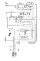
- Atmospheric air 1 is in FIG. 1 sucked by a main air compressor 3 with aftercooler 4 via a filter 2 and there to a first total air pressure of 3.1 bar compacted.
- the main air compressor may have two or more stages with intercooling; it is preferably designed for redundancy reasons two-stranded (both not shown in the drawing).
- the total air flow 5 is supplied under the first total air pressure and a temperature of 295 K to a first direct contact cooler 6 and cooled there in direct heat exchange with cooling water 7 from an evaporative cooler 8 further to 283 K.
- the cooled total air flow 9 is divided into a first partial air flow 10 and a second partial air flow 11.
- the second partial air stream 11 is compressed in a secondary compressor 12 with aftercooler 13 from the first total air pressure (minus pressure losses) to a second total air pressure of 4.9 bar.
- the booster may have two or more intermediate cooling stages; it is preferably designed for redundancy reasons two-stranded (both not shown in the drawing). Depending on a strand of the main air compressor and the Nachverêtrs may be designed as a machine with a common drive, in particular as a transmission compressor.
- the second partial air stream 14 is then cooled in a second direct-contact cooler 15 from 295 K to 290 K, in direct heat exchange with a, warmer cooling water stream 16th
- the first partial air stream is cleaned in a first cleaning device 18, which is operated under the first total air pressure, and then fed via line 19 under this pressure to the warm end of a main heat exchanger, which is formed in the embodiment by two blocks 20, 21 connected in parallel.
- the cooled to about dew point air forms a "first feed air stream", which is a first high-pressure column 23 is supplied.
- the first high-pressure column 23 is part of a distillation column system for nitrogen-oxygen separation, which also has a second high pressure column 24, a low pressure column consisting of two gates 25, 26, a low-pressure column intermediate evaporator 27, a low-pressure column sump evaporator 28 and a secondary condenser 29th having.
- the low-pressure column intermediate evaporator 27 and the low-pressure column bottom evaporator 28 are formed as a falling film evaporator, the secondary condenser 29 as a bath evaporator.
- the pre-cooled second partial air stream 17 is cleaned in a second cleaning device 30, which is operated under the second total air pressure. From the purified second partial air stream, a small part can be removed via line 32, which is used as instrument air or for purposes outside the air separation. The remainder flows via line 33 to the main heat exchanger 20 and is cooled there.
- the cooled second partial air stream 34 is divided into a "second feed air stream" 35, which is introduced into the second high-pressure column 24, and into a "third feed air stream” 36, which is fed to the liquefaction space of the secondary condenser 29.
- the at least partially, preferably substantially completely condensed, third substream 37 is introduced into a separator (phase separator) 38.
- the liquid portion 39 is supplied to a first part 40 of the first high-pressure column 23.
- To a second part 41 it is fed via a supercooling countercurrent 42 and line 43 in the low-pressure column 26.
- Nitrogen-rich overhead gas 44 of the first high-pressure column 23 is condensed to a first part in the low-pressure column intermediate evaporator 27.
- recovered liquid nitrogen 46 is fed to a first part 47 as reflux to the top of the first high-pressure column 23.
- a second part 48 is cooled in the subcooling countercurrent 42 and fed via line 49 as reflux to the top of the low pressure column 26.
- a portion 50 of the supercooled liquid can be recovered as needed as a liquid product (LIN).
- a second portion 51 of the nitrogen-rich overhead gas 44 of the first high-pressure column 23 is heated in the main heat exchanger 20 to an intermediate temperature.
- the warmed pressurized nitrogen 52 is expanded in a generator-restricted pressure nitrogen turbine 53 from 2.7 bar to 1.25 bar to perform work.
- the outlet pressure of the turbine is just enough to push the work-performing expanded flow 54 through the main heat exchanger 20 and via the lines 55, 56, 57 as regeneration gas through the first and the second cleaning device 18, 30.
- Nitrogen-rich top gas 58 of the second high-pressure column 24 is condensed in the low-pressure column bottom evaporator 28. Liquid nitrogen 59 obtained in the process is transferred to a first part 60 as reflux to the head of the second
- High pressure column 24 abandoned.
- a second part 61 is cooled in the subcooling countercurrent 42 and fed via line 62 as reflux to the top of the low pressure column 26.
- the bottom liquids 63, 64 of the two high pressure columns 23, 24 are brought together, fed via line 65, the subcooling countercurrent 42 and line 66 in the low pressure column 26.
- the bottom liquid 66 of the low-pressure column 25 is introduced into the evaporation space of the low-pressure column bottom evaporator 28 and partially evaporated there.
- the liquid remaining portion 67 flows into the evaporation space of the secondary condenser 29 and is partially evaporated there.
- the vaporized portion 68 is directed to the cold end of the main heat exchanger block 20, warmed to about ambient temperature and finally recovered via line 69 as gaseous oxygen product (GOX) of a purity of 95 mol%.
- GOX gaseous oxygen product
- the liquid remaining fraction is evaporated to a part 70 in a pump 71 to a pressure of 6 bar, in the main heat exchanger block 21 and warmed and finally admixed with the gaseous oxygen product 69.
- Another portion 72 may be obtained via the subcooling countercurrent 42, pump 73, and conduit 74 as a liquid oxygen product (LOX).
- a liquid intermediate fraction 75 which is obtained at the lower end of the second low-pressure column section 26, is conveyed by means of a pump 76 into the evaporation space of the low-pressure column intermediate evaporator 27 and partially evaporated there. Steam generated in this process, together with the vapor accumulating at the top of the first low-pressure column section 25, is passed via lines 77 and 79 into the second low-pressure column section 26, optionally together with circulating flushing liquid 78. The remainder of the liquid remaining intermediate fraction serves as reflux liquid in the first low-pressure column section 25.
- nitrogen-rich residual gas 80 is withdrawn under a pressure of 1.26 bar and fed after warming in supercooling countercurrent 42 and main heat exchanger 20 via line 81 virtually pressureless as dry gas into the evaporative cooler 8 and used there for cooling of cooling water 82 ,
- FIG. 2 differs from two procedural sections of FIG. 1 namely, refrigeration and air compression with pre-cooling and cleaning.
- refrigeration and air compression with pre-cooling and cleaning are two procedural sections of FIG. 1 namely, refrigeration and air compression with pre-cooling and cleaning.
- Cold is not generated here by a pressurized nitrogen turbine, but by an injection turbine 153. This is operated with a "fourth feed air stream" 151, 152, which was branched from the first partial air flow 119 at the lower first total air pressure and cooled in the main heat exchanger 20 to an intermediate temperature.
- the working expanded fourth feed air stream 154 is supplied to the low pressure column 26 at a suitable intermediate point.
- the air compression is simpler than in FIG. 1 and in particular has only one single cleaning device 118, in which the total air 105, 110 is cleaned under the first total air pressure. Only a direct contact cooler 106 is used.
- the division into the first partial air flow 119 and the second partial air flow 111 is carried out downstream of the cleaning device 118.
- the after-compressor 112 is as in FIG FIG. 1 constructed, but has only a conventional aftercooler 113 and the air is not further cooled in a direct contact cooler. Via line 119 then the second partial air stream is analogous to line 19 in FIG. 1 guided.
- the low-pressure column intermediate evaporator 27, the first section 25 of the low-pressure column, the low-pressure column bottom evaporator 28 and the secondary condenser 29 are arranged one above the other.
- the first high-pressure column 23 is arranged next to the first section 25 of the low-pressure column. (In between, there is especially the second high-pressure column 24.) Again, next to the first section 25 is the second section 26 of the low-pressure column.
- the four column sections can basically assume any position relative to one another. In one extreme case, they are all aligned along a horizontal straight line, in the other extreme case at the corners of a quadrangle, in particular a rectangle, in particular a square arranged.
- FIG. 3 corresponds largely FIG. 1 ,
- the warm section of the procedure is not pictured and may be as in FIG. 1 or as in FIG. 2 be educated.
- a high-pressure feed air stream 233 is introduced into the main heat exchanger 20.
- the cold high pressure feed air stream 235 enters a third high pressure column 224 at a third pressure of 5.3 bar.
- the nitrogen-rich overhead gas 258 is used as heating medium in the secondary condenser 228 and condensed there substantially completely.
- liquid nitrogen 259 obtained is fed to a first part 260 as reflux to the top of the second high-pressure column 24.
- a second portion 261 is cooled in the subcooling countercurrent 42 and fed via line 262 as reflux to the top of the low pressure column 26.
- the secondary condenser 228 is embodied in this embodiment as a multi-storey bath evaporator, in particular as a cascade evaporator, in which the individual floors are connected in parallel on the evaporation side in series and on the liquefaction side.
- any corresponding embodiment of a cascade evaporator can be used, in particular those which are described in detail in FIG EP 1077356 A1 .
- WO 0192798 A2 US 2005028554 A1 .
- WO 01092799 A1 US 2003159810 A1 .
- the third high pressure column 224 is as in FIG. 3 shown, preferably below the secondary condenser 228 or the combination of secondary condenser 228, low-pressure column bottom evaporator, first section of the low-pressure column and low-pressure column intermediate evaporator.
- the spatial arrangement of the remaining columns corresponds to that of the FIGS. 1 and 2 ,
Priority Applications (6)
| Application Number | Priority Date | Filing Date | Title |
|---|---|---|---|
| EP12762536.6A EP2758734B1 (fr) | 2011-09-20 | 2012-09-20 | Procédé et dispositif destinés à la décomposition à basse température d'air |
| US14/345,840 US10443931B2 (en) | 2011-09-20 | 2012-09-20 | Method and device for the cryogenic decomposition of air |
| PCT/EP2012/003944 WO2013041229A1 (fr) | 2011-09-20 | 2012-09-20 | Procédé et dispositif de séparation cryogénique de l'air |
| PL12762536T PL2758734T3 (pl) | 2011-09-20 | 2012-09-20 | Sposób i urządzenie do niskotemperaturowego rozkładu powietrza |
| AU2012311959A AU2012311959B2 (en) | 2011-09-20 | 2012-09-20 | Method and device for the cryogenic decomposition of air |
| CN201280046019.9A CN103998883B (zh) | 2011-09-20 | 2012-09-20 | 低温分离空气的方法和设备 |
Applications Claiming Priority (1)
| Application Number | Priority Date | Filing Date | Title |
|---|---|---|---|
| DE201110113668 DE102011113668A1 (de) | 2011-09-20 | 2011-09-20 | Verfahren und Vorrichtung zur Tieftemperaturzerlegung von Luft |
Publications (1)
| Publication Number | Publication Date |
|---|---|
| EP2573492A1 true EP2573492A1 (fr) | 2013-03-27 |
Family
ID=44862342
Family Applications (1)
| Application Number | Title | Priority Date | Filing Date |
|---|---|---|---|
| EP11008534A Withdrawn EP2573492A1 (fr) | 2011-09-20 | 2011-10-25 | Procédé et dispositif destinés à la décomposition à basse température d'air |
Country Status (2)
| Country | Link |
|---|---|
| EP (1) | EP2573492A1 (fr) |
| DE (1) | DE102011113668A1 (fr) |
Cited By (2)
| Publication number | Priority date | Publication date | Assignee | Title |
|---|---|---|---|---|
| WO2012127148A3 (fr) * | 2011-03-18 | 2014-12-04 | L'air Liquide, Societe Anonyme Pour L'etude Et L'exploitation Des Procedes Georges Claude | Appareil et procede de separation d'air par distillation cryogenique |
| CN114026376A (zh) * | 2019-10-17 | 2022-02-08 | 普莱克斯技术有限公司 | 用于在具有多个低温空气分离单元的空气分离设备设施或包体中产生氩的系统和方法 |
Citations (11)
| Publication number | Priority date | Publication date | Assignee | Title |
|---|---|---|---|---|
| DE19609490A1 (de) | 1995-03-10 | 1996-09-12 | Linde Ag | Verfahren und Vorrichtung zur Tieftemperaturzerlegung von Luft |
| US5765397A (en) * | 1996-10-28 | 1998-06-16 | Nippon Sanso Corporation | Air liquefaction separation process and apparatus therefor |
| EP1077356A1 (fr) | 1999-08-19 | 2001-02-21 | Linde Aktiengesellschaft | Condenseur à circulation multiétagé |
| DE10009977A1 (de) | 2000-03-03 | 2001-09-06 | Linde Ag | Verfahren und Vorrichtung zur Tieftemperaturzerlegung von Luft |
| WO2001092799A1 (fr) | 2000-05-31 | 2001-12-06 | Linde Ag | Condenseur a bain a plusieurs etages |
| WO2001092798A2 (fr) | 2000-05-31 | 2001-12-06 | Linde Ag | Condenseur a bain a plusieurs etages |
| DE20205751U1 (de) * | 2001-12-12 | 2002-07-11 | Linde Ag | Vorrichtung zur Tieftemperatur-Zerlegung von Luft |
| WO2003012352A2 (fr) | 2001-07-30 | 2003-02-13 | Linde Aktiengesellschaft | Condensateur-evaporateur a plusieurs etages |
| EP1413840A1 (fr) * | 2002-10-23 | 2004-04-28 | Linde Aktiengesellschaft | Procédé et dispositif de production variable d'oxygen par séparation cryogénique d'air |
| DE202006004478U1 (de) * | 2006-03-21 | 2006-06-01 | Linde Aktiengesellschaft | Vorrichtung zur Tieftemperaturzerlegung von Luft |
| DE102007003437A1 (de) | 2007-01-23 | 2007-09-20 | Linde Ag | Mehrstöckiger Badkondensator im Flüssigkeitsbad |
-
2011
- 2011-09-20 DE DE201110113668 patent/DE102011113668A1/de not_active Withdrawn
- 2011-10-25 EP EP11008534A patent/EP2573492A1/fr not_active Withdrawn
Patent Citations (14)
| Publication number | Priority date | Publication date | Assignee | Title |
|---|---|---|---|---|
| DE19609490A1 (de) | 1995-03-10 | 1996-09-12 | Linde Ag | Verfahren und Vorrichtung zur Tieftemperaturzerlegung von Luft |
| US5669237A (en) | 1995-03-10 | 1997-09-23 | Linde Aktiengesellschaft | Method and apparatus for the low-temperature fractionation of air |
| US5765397A (en) * | 1996-10-28 | 1998-06-16 | Nippon Sanso Corporation | Air liquefaction separation process and apparatus therefor |
| EP1077356A1 (fr) | 1999-08-19 | 2001-02-21 | Linde Aktiengesellschaft | Condenseur à circulation multiétagé |
| DE10009977A1 (de) | 2000-03-03 | 2001-09-06 | Linde Ag | Verfahren und Vorrichtung zur Tieftemperaturzerlegung von Luft |
| WO2001092798A2 (fr) | 2000-05-31 | 2001-12-06 | Linde Ag | Condenseur a bain a plusieurs etages |
| WO2001092799A1 (fr) | 2000-05-31 | 2001-12-06 | Linde Ag | Condenseur a bain a plusieurs etages |
| US20030159810A1 (en) | 2000-05-31 | 2003-08-28 | Schweigert Karl Heinrich | Multistoreyed bath condenser |
| US20050028554A1 (en) | 2000-05-31 | 2005-02-10 | Alfred Wanner | Multistoreyed bath condenser |
| WO2003012352A2 (fr) | 2001-07-30 | 2003-02-13 | Linde Aktiengesellschaft | Condensateur-evaporateur a plusieurs etages |
| DE20205751U1 (de) * | 2001-12-12 | 2002-07-11 | Linde Ag | Vorrichtung zur Tieftemperatur-Zerlegung von Luft |
| EP1413840A1 (fr) * | 2002-10-23 | 2004-04-28 | Linde Aktiengesellschaft | Procédé et dispositif de production variable d'oxygen par séparation cryogénique d'air |
| DE202006004478U1 (de) * | 2006-03-21 | 2006-06-01 | Linde Aktiengesellschaft | Vorrichtung zur Tieftemperaturzerlegung von Luft |
| DE102007003437A1 (de) | 2007-01-23 | 2007-09-20 | Linde Ag | Mehrstöckiger Badkondensator im Flüssigkeitsbad |
Cited By (3)
| Publication number | Priority date | Publication date | Assignee | Title |
|---|---|---|---|---|
| WO2012127148A3 (fr) * | 2011-03-18 | 2014-12-04 | L'air Liquide, Societe Anonyme Pour L'etude Et L'exploitation Des Procedes Georges Claude | Appareil et procede de separation d'air par distillation cryogenique |
| CN114026376A (zh) * | 2019-10-17 | 2022-02-08 | 普莱克斯技术有限公司 | 用于在具有多个低温空气分离单元的空气分离设备设施或包体中产生氩的系统和方法 |
| CN114026376B (zh) * | 2019-10-17 | 2023-04-04 | 普莱克斯技术有限公司 | 用于产生氩的系统和方法 |
Also Published As
| Publication number | Publication date |
|---|---|
| DE102011113668A1 (de) | 2013-03-21 |
Similar Documents
| Publication | Publication Date | Title |
|---|---|---|
| EP1308680B1 (fr) | Procédé et dispositif de production de krypton et/ou xénon par distillation cryogénique de l'air | |
| DE69612532T3 (de) | Verfahren und Vorrichtung zur Herstellung von Sauerstoff mässiger Reinheit | |
| EP1067345B1 (fr) | Procédé et dispositif pour la séparation cryogénique des constituants de l'air | |
| EP2236964B1 (fr) | Procédé et dispositif de séparation de l'air à basse température | |
| EP2458311A1 (fr) | Procédé et dispositif de production d'un produit d'impression gazeux par décomposition à basse température d'air | |
| EP2026024A1 (fr) | Procédé et dispositif pour la production d'argon par séparation cryogénique d'air | |
| EP2758734B1 (fr) | Procédé et dispositif destinés à la décomposition à basse température d'air | |
| EP2520886A1 (fr) | Procédé et dispositif de production d'un produit comprimé à oxygène gazeux par décomposition à basse température d'air | |
| DE10018200A1 (de) | Verfahren und Vorrichtung zur Gewinnung von Druckstickstoff durch Tieftemperaturzerlegung von Luft | |
| EP2603754A2 (fr) | Procédé et dispositif permettant d'obtenir de l'oxygène sous pression et de l'azote sous pression par fractionnement cryogénique de l'air | |
| EP3290843A2 (fr) | Procédé et dispositif destiné à fabriquer de l'azote pressurisé et liquide par décomposition à basse température de l'air | |
| WO2014146779A2 (fr) | Procédé et dispositif de production d'azote gazeux sous pression | |
| WO2013053425A2 (fr) | Procédé et dispositif de production de deux courants d'air partiels purifiés | |
| WO2016146246A1 (fr) | Système permettant de produire de l'oxygène par fractionnement d'air à basse température | |
| EP1319913A1 (fr) | Appareil et procédé de production d'oxygène gazeux sous pression élevée | |
| EP2551619A1 (fr) | Procédé et dispositif destinés à l'obtention d'oxygène pressurisé et d'azote pressurisé par la décomposition à basse température de l'air | |
| WO2021078405A1 (fr) | Procédé et système pour la séparation d'air à basse température | |
| EP2938952A2 (fr) | Procédé et dispositif de séparation de l'air à basse température | |
| EP3980705A1 (fr) | Procédé et installation de décomposition d'air à basse température | |
| EP2573492A1 (fr) | Procédé et dispositif destinés à la décomposition à basse température d'air | |
| EP3394536A1 (fr) | Procédé et dispositif de production d'azote pur et d'oxygène pur par séparation cryogénique d'air | |
| DE10153919A1 (de) | Verfahren und Vorrichtung zur Gewinnung hoch reinen Sauerstoffs aus weniger reinem Sauerstoff | |
| DE102011113671A1 (de) | Verfahren und Vorrichtung zur Tieftemperaturzerlegung von Luft | |
| DE20319823U1 (de) | Vorrichtung zur Gewinnung von Krypton und/oder Xenon durch Tieftemperaturzerlegung | |
| EP2865978A1 (fr) | Procédé de décomposition à basse température de l'air et installation de décomposition de l'air à basse température |
Legal Events
| Date | Code | Title | Description |
|---|---|---|---|
| PUAI | Public reference made under article 153(3) epc to a published international application that has entered the european phase |
Free format text: ORIGINAL CODE: 0009012 |
|
| AK | Designated contracting states |
Kind code of ref document: A1 Designated state(s): AL AT BE BG CH CY CZ DE DK EE ES FI FR GB GR HR HU IE IS IT LI LT LU LV MC MK MT NL NO PL PT RO RS SE SI SK SM TR |
|
| AX | Request for extension of the european patent |
Extension state: BA ME |
|
| STAA | Information on the status of an ep patent application or granted ep patent |
Free format text: STATUS: THE APPLICATION IS DEEMED TO BE WITHDRAWN |
|
| 18D | Application deemed to be withdrawn |
Effective date: 20130928 |