EP2573403A1 - Pump - Google Patents
Pump Download PDFInfo
- Publication number
- EP2573403A1 EP2573403A1 EP11007661A EP11007661A EP2573403A1 EP 2573403 A1 EP2573403 A1 EP 2573403A1 EP 11007661 A EP11007661 A EP 11007661A EP 11007661 A EP11007661 A EP 11007661A EP 2573403 A1 EP2573403 A1 EP 2573403A1
- Authority
- EP
- European Patent Office
- Prior art keywords
- pump
- user
- user application
- electrically driven
- data information
- Prior art date
- Legal status (The legal status is an assumption and is not a legal conclusion. Google has not performed a legal analysis and makes no representation as to the accuracy of the status listed.)
- Granted
Links
- 230000000694 effects Effects 0.000 claims description 3
- 230000006870 function Effects 0.000 description 10
- 230000008901 benefit Effects 0.000 description 7
- 238000005086 pumping Methods 0.000 description 4
- 230000009286 beneficial effect Effects 0.000 description 3
- 238000013500 data storage Methods 0.000 description 2
- 230000003247 decreasing effect Effects 0.000 description 2
- 230000000007 visual effect Effects 0.000 description 2
- 238000001816 cooling Methods 0.000 description 1
- 239000000110 cooling liquid Substances 0.000 description 1
- 230000003203 everyday effect Effects 0.000 description 1
- 239000012530 fluid Substances 0.000 description 1
- 238000010438 heat treatment Methods 0.000 description 1
- 238000000034 method Methods 0.000 description 1
- 230000002093 peripheral effect Effects 0.000 description 1
- 230000001105 regulatory effect Effects 0.000 description 1
- 230000036962 time dependent Effects 0.000 description 1
- XLYOFNOQVPJJNP-UHFFFAOYSA-N water Substances O XLYOFNOQVPJJNP-UHFFFAOYSA-N 0.000 description 1
Images


Classifications
-
- F—MECHANICAL ENGINEERING; LIGHTING; HEATING; WEAPONS; BLASTING
- F04—POSITIVE - DISPLACEMENT MACHINES FOR LIQUIDS; PUMPS FOR LIQUIDS OR ELASTIC FLUIDS
- F04D—NON-POSITIVE-DISPLACEMENT PUMPS
- F04D15/00—Control, e.g. regulation, of pumps, pumping installations or systems
-
- G—PHYSICS
- G05—CONTROLLING; REGULATING
- G05D—SYSTEMS FOR CONTROLLING OR REGULATING NON-ELECTRIC VARIABLES
- G05D7/00—Control of flow
- G05D7/06—Control of flow characterised by the use of electric means
-
- F—MECHANICAL ENGINEERING; LIGHTING; HEATING; WEAPONS; BLASTING
- F04—POSITIVE - DISPLACEMENT MACHINES FOR LIQUIDS; PUMPS FOR LIQUIDS OR ELASTIC FLUIDS
- F04D—NON-POSITIVE-DISPLACEMENT PUMPS
- F04D15/00—Control, e.g. regulation, of pumps, pumping installations or systems
- F04D15/0066—Control, e.g. regulation, of pumps, pumping installations or systems by changing the speed, e.g. of the driving engine
Definitions
- the present invention generally relates to a pump.
- the invention more particularly relates to a pump having an interface for receiving data information that can be executed by the pump's microprocessor.
- Circulator pumps are often intended to deliver a specific head and flow rate at given circumstances in order to meet preset requirements.
- the pump will be equipped with a standard control that is delivered with a limited number of user options and applications.
- Prior art pumps may be controlled according to the control patterns that the pump control is provided with. Some pump controls are configured to be adjusted by changing one or more parameters. Adjusting may be done by the user of the pump, e.g. by using an interface that is integrated in the control device.
- the pump will not be able to perform according to the user's specific requirement. This is a major challenge for many users.
- the pump according to the invention is an electrically driven pump comprising an electrical motor; a control device that comprises storage means and a microprocessor and is configured to receive data information.
- the control device is adapted to control the activity of the motor.
- the storage means comprises a user application storage and an interpreter storage and the control device is configured to receive data information that constitutes a user application that can be executed by the pump's microprocessor as one or more user application sequences.
- the pump according to the invention is capable of adjusting the control device according to specific needs (e.g. specific user needs) even if the needs require a specific application that is not already present in the control device.
- a pump according to the invention may eliminate the need for an external pump controller in demanding applications, since the control device within the pump can be programmed in a way that makes it possible to operate the pump according to specific requirements.
- the pump according to the invention may be setup by the user in order to meet user specific requirements that cannot be met by using prior art pumps.
- a user application may be understood as a kind of "micro".
- the electrical motor may, in principle be any electrical motor suitable for driving a pump. It may be an advantage if the electrical motor is equipped with a frequency converter for regulating the speed of the motor.
- the motor may be a permanent magnet motor that is controlled by a frequency converter. Thus it would be possible to adapt the speed of the pump to specific requirements and hereby save energy.
- control device is provided in a control box that is arranged on the motor or next to the motor.
- the storage means may be any suitable type of computer data storage.
- the storage means may be any physical device configured to store data or a sequence of instructions constituting a user application on a temporary or permanent basis.
- data information information in a form suitable for use with the control device.
- the data information may be any suitable type of information that can be received by the control device.
- the data information may, for instance, be a sequence of instructions constituting a program or data indicating or representing a set point e.g. for the temperature, at which the control device is intended to switch off the electric motor.
- user application an application that can be executed by the pump's microprocessor.
- the user application may comprise one or more sequences.
- a user application can be used to control a pump in a user specific manner.
- a user application may comprise one or more conditions that have to be fulfilled in order to carry out an action.
- a user application may include a program in any suitable form.
- An action may, by way of example, be increasing the speed of the pump from a first level to a higher level.
- a user application may be a user defined user application meaning that the user of the pump (or the installer of the pump) defines and/or creates the user application.
- control device is configured to receive data information that constitutes a user application applying a time scalar parameter.
- time can be taken into account when an action is carried out.
- the actions can be time-dependent.
- the user application storage is a storage that is allocated for storing of user applications.
- the interpreter storage is a storage that is allocated for storing of an interpreter that is configured to interpret the user applications stored in the user application storage.
- the object of the present invention can be achieved by a pump having the features defined in claim 1.
- control device is configured to receive data information comprising one or more operators, one or more scalar parameters, and one or more actions, where the data information constitute a user application that can be executed by the pump's microprocessor as one or more user application sequences.
- control device is configured to receive data information that comprises one or more logical operators and one or more scalar parameters, one or more actions and one or more units, where the data information constitutes a user application that can be executed by the pump's microprocessor as one or more user application sequences.
- the pump is well suited for being setup according to typical requirements that can be expressed in one or more user applications that comprises one or more logical operators and one or more scalar parameter, one or more actions and one or more units.
- the pump will be suited to meet most user requirements.
- the pump is configured to receive data information from one or more external devices and that the pump is configured to be controlled on the basis of the data information that is sent to the storage means of the control device from one or more external devices, that the data information that is sent to the storage means constitute a user application that is suitable for being executed by the pump's microprocessor, as one or more user application sequences.
- the one or more external devices may be used to adjust the pump. It is possible to use several types of external devices to send data information to the pump.
- the pump comprises an interface that is configured to be used to provide data information to the storage means and that the data information constitute a user application that is suitable for being executed by the pump's microprocessor.
- the interface may be any type of interface that the user of the pump can use to communicate with the control device.
- the interface may be a peripheral device such as a keyboard, a touch screen, or a remote control.
- the pump comprises a display that is configured to display a number of preset icons that correspond to a list of operators, parameters, and actions and that a user application can be made by selecting between the preset icons.
- the user can generate a user application in a quick and easy way.
- the user may select the icons from a list.
- the display may be any type of suitable displays.
- the display may, by way of example, be an electronic visual display such as a touch screen that may be used to input data to the pump.
- the pump comprises a display that is configured to display a number of preset icons that correspond to a list of operators, parameters, units, and actions and that a user application can be made by selecting between the preset icons.
- the pump is configured to receive or upload user applications through a web forum or a web service.
- the user of the pump may upload and download user applications to the pump so that the pump becomes capable of performing in accordance with specific requirements. It is also possible for the user to upload user applications. In this way other users may benefit from using the uploaded user applications.
- the pump is configured to receive user applications through a web service or a web forum.
- the user of the pump may download user applications to the pump automatically from the Internet. It is possible to provide the pump with information that makes the pump capable of downloading user applications to make it capable of performing in accordance with user specific requirements.
- the pump is capable of only downloading user applications that are relevant to the specific pump type. This may be accomplished by using a specific pump information tag that is registered by the server, from which the user applications are being downloaded.
- the specific pump information tag may be any type of code or suitable tag that can be registered by the server from which the user applications are being downloaded.
- the pump is configured to receive user applications through an external storage means that is configured to be connected to the pump.
- the external storage means may be plugged into the pump or into the control device of the pump, however; it may also be an external storage type that communicates wirelessly with the pump.
- the external storage means may be any suitable type of hardware including an electronic flash memory data storage device, a hard disk, USB flash drive by way of example.
- the pump is configured to receive user applications that is sent to the pump.
- the pump is configured to receive user applications via an email that is sent to the pump.
- the pump can be provided with specific user applications that are directed towards the pump. It is possible to send an email every time new applications are available for the pump.
- the pump is coupled to the Internet and the pump is configured to upload pump specific information to an external receiver and the pump is configured to perform automatic and selective download of user applications that are suitable for the specific pump type.
- the pump is capable of downloading relevant user applications that is intended to be used in that specific pump type.
- the pump is connected to the Internet and is configured to perform automatic and selective download of information (e.g. weather forecast information) and use this information in one or more user applications on the basis of one or more preset criteria.
- information e.g. weather forecast information
- the pump will be capable of receiving information (e.g. about the weather) and use this information to adjust its operation. If, for example, the weather forecast anticipates a decreasing temperature the pump may change the user applications so that the pump is activated to a higher temperature threshold than before. This would be a desirable solution for a circulator pump according to the invention. It is important to underline that any relevant type of information may be used to adjust the operation of the pump.
- the pump may be a centrifugal pump.
- the pump may be a circulator pump configured to circulate a fluid such as water or a cooling liquid.
- the circulator may, by way of example, be used for heating or cooling purposes.
- the pump is driven by a motor that is equipped with a frequency converter.
- the pump comprises a storage having a user application storage that is configured to store user applications; a basic function storage that is used to store basic applications, and an interpreter storage that is allocated for an interpreter that is configured to carry out interpretation of the user applications that are stored in the user application storage.
- the pump has an interface comprising a keyboard and/or a track ball and/or a touch screen for inputting information into the control device.
- the pump comprises a control device that is configured to turn the motor on and off and to change the speed of the motor.
- the pump comprises at least one sensor
- a pump 2 according to a preferred embodiment of the present invention is illustrated in Fig. 1 .
- the pump 2 comprises a control device 4 arranged in a control box; storage means 6; a microprocessor 8; an interface 28 and a display 30.
- a computer 24 is connected to the pump 2 via a cable 26. Data information can be provided to the pump's storage means 6 by using the computer 24.
- the computer 24 may be connected to the Internet from where it would be possible to download user applications. It would also be possible to create user applications directly on the computer 24 and send the user applications. It would also be possible to use the computer as a display in case that the pump does not have a display 30.
- the user of the pump 2 may use a handheld device e.g. mobile phone 42 to send data information to the storage means 6 of the pump 2. It would also be possible to use a remote control 40 to send data information to the pump's storage means 6.
- the display 30 of the pump 2 shows a number of icons 32. The user of the pump 2 can easily compose a user application 18 by using these icons 32.
- the pump 2 comprises a visual display 30 that is a touch screen that may be used to input data and hereby create a user application 18 (see Fig. 6 ).
- the control device 4 may be arranged in a control box that is arranged on the motor of the pump 2 or adjacent to the motor of the pump 2. However, the control device 4 may be arranged in a box that is mechanically separated from the pump 2 and electrically connected to the pump 2 via a cable. Preferable the control device 4 comprises means for sending and receiving information, for instance by using radio communication.
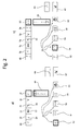
- Fig. 2 a) illustrates one way of creating a user application 18.
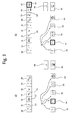
- Fig. 3 a) and Fig. 3 b) show the views of a display 30 during creation of a user application 18.
- the variable box 52 is highlighted and symbolised by a question mark "?”, that represents a variable, which by way of example, may be temperature or pressure.
- the box 68 shows that the user application 18 comprises a sequence that begins with a temperature variable. The temperature is indicated with a "T" in the box 68.
- the operator may be a logical operator but it does not have to be; however, the operator box 70 shows that the second symbol in the user application sequence is a "less than” symbol ( ⁇ ) indicating that temperatures below a certain limit is essential for the user application 18.
- the pump 2 comprises a temperature sensor.
- the box 56 symbolises numerical values that can be selected by the user of the pump 2.
- the eligible numerical values are symbolised by the numbers "1 2 3".
- the box 72 shows that the third symbol in the user application sequence is a scalar parameter 12 and that it has the value 80.
- the box 58 symbolises a unit that can be selected by the user of the pump 2.
- the unit box 58 is symbolised by the symbol "[ ]".
- the box 74 shows that the fourth symbol in the user application sequence is the unit 16 is a temperature unit "°C”.
- the box 60 symbolises an action that can be carried out (e.g. start or stop of the motor of the pump 2).
- the action box 60 is symbolised by a traditional start/stop symbol.
- the new line box 64 is used to make a new line and the save and run box 62 is used to save and run the user application.
- the box 76 shows a logical operator "or” indicated by the mathematical symbol "V" for or.
- the first box 78 from the right is highlighted and the user has selected to input a variable (that is why the variable box 52 is highlighted). Below the box 78 a drop-down menu box 66 appears and the selected variable is temperature; indicated with the symbol "T".
- control device 4 is configured to provide an explanation of all symbols to the user.
- the explanation may be disclosed in any suitable way, e.g. by demand of the user that may press on a help function key (not shown).
- Fig. 2 b illustrates a view of a display 30 where the user continues to compose the user application 18 that is illustrated in Fig. 2 a.
- the user has selected the symbol box 54 and therefore the symbol box 54 is highlighted.
- an additional box 80 has been created by the user and this box 80 appears to the right in the upper area of the display.
- the drop down menu 66 the user has selected the symbol "decreasing" indicated by a downwards directed arrow.
- Fig. 3 a) The further composition of the user application 18 is illustrated in Fig. 3 a) and Fig. 3 b) .
- Fig. 3 a) it can be seen that the downwards directed arrow is shown in box 80.
- Fig. 3 b) the user application 18 is completed and the numerical value box 72 shows 2.
- the unit box 74 shows a unit 16' that is a temperature per time unit "°C/min" and the action box 82 shows the action 14 MIN.
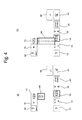
- Fig. 4 illustrates composition of another user application 18.
- This user application 18 is intended to control the pump operation according to a voltage input.
- the user of the pump 2 has selected an input "Input 1" in the variable box 68.
- "input 1" may be any suitable type of input.
- the user has just selected the numerical value box 72 and the drop-down menu box 66 gives a list that the user can choose from.
- the user is selecting the first digit of the numerical value. This first digit is "0".
- Fig. 5 a it can be seen that the first digit of the numerical value is "0" indicated in the numerical value box 72.
- Fig. 5 b) the second digit of the numerical value has been selected from drop-down menu box 66. The second digit is "1" and thus the value is "10" as illustrated in the numerical value box 72 in Fig. 5 b) .
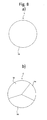
- Fig. 6 a the user application sequence 88 is shown. This user application sequence 88 reads: if input 1 is greater than or equal to 10 volt then the set point is 100%.
- Fig. 6 b illustrates a user application 18 comprising four user application sequence sections 86, 88, 90, 92.
- the first section 86 defines that if the input voltage is below 10 volt and above 3 volt then the set point is adjusted linearly between 10% and 100% according to the input voltage. This is illustrated by a linear curve symbol 22.
- the second section 88 defines that if the input voltage is larger than or equal to 10 volt then the set point is set to 100%.
- the third section 90 defines that if the input voltage is 3 volt then the set point is set to 10%.
- the fourth section 92 defines that if the input voltage is lower than 3 volt then the pump stops.
- Fig. 7 illustrates a user application 18 having two lines 94, 96.
- the first line 94 defines that if the head exceeds 4 meters (indicated with "m") then the pump 2 stops.
- the second line 96 defines that if the head equals or falls below 2 m then the pump 2 is activated. It is possible to have a huge number of various user applications 18.
- One example of such user application 18 may define that the pump 2 is set to start at the same hour every day.
- Fig 8 a is a schematical view of a storage 6 of a control device for a prior art pump.
- the storage 6 comprises a basic function storage 36 that is used to store basic applications. These basic applications may be any type of application that is needed for carrying out the basic function of the pump 2.
- the user of the pump can change settings and parameters in the basic function storage 36 thus programming the preset applications to the requested needs according to prior art.
- the user of the pump is restricted from creating new applications that are not already included in the basic function storage 36.
- Fig. 8 b is a schematical view of a storage 6 according to the invention.
- the storage 6 comprises a user application storage 34 that is configured to store user applications 18. These user applications 18 may, by way of example, be composed by the user or may be pre-installed. The user applications may also be downloaded to the user application storage 34.
- the storage 6 further more comprises a basic function storage 36 that is used to store basic applications. These basic applications may be any type of application that is needed for carrying out the basic function of the pump 2.
- the storage 6 moreover comprises an interpreter storage 38 that is allocated for the interpretation and execution of the user applications 18 that are stored in the user application storage 34.
- the user of the pump 2 can create user applications that can be user specific and meet individual user requirements.
- Fig. 9 is a schematical view of a pump 2 according to one embodiment of the invention.
- the pump 2 is configured to communicate via the Internet 44.
- Information and data such as user applications 18 may be uploaded and downloaded to the pump 2.
- Weather forecast information 48 may, by way of example, be sent to the pump 2.
- the pump 2 may also upload pump specific information 46 to an external receiver 39 by using the Internet 44.
- An external memory 50 is provided so that it would be possible to apply user applications 18 that are stored in the external memory 50.
- the user applications 18 may, by way of example, be downloaded from the Internet 44 to the external memory 50.
- a mobile phone 44 - Internet 46 - Pump specific information 48 - Weather forecast information 50 - External storage means 52 - Variable box 54 - Symbol box 56 - Numerical value box 58 - Unit box 60 - Action box 62 - Save and run box 64 - New line box 66 - Drop-down menu box 68, 70, 72, 74, - Boxes 76, 78, 80, 82 - Boxes 86 - First user application sequence 88 - Second user application sequence 90 - Third user application sequence 92 - Fourth user application sequence 94 - First line 96 - Second line
Abstract
Description
- The present invention generally relates to a pump. The invention more particularly relates to a pump having an interface for receiving data information that can be executed by the pump's microprocessor.
- Many modern pumps are provided with various types of controls in order to control the pumps in specific ways. Circulator pumps are often intended to deliver a specific head and flow rate at given circumstances in order to meet preset requirements. When a pump has been developed, produced and sold there will always be several users that have specific requirements that cannot be met by using the pump. The pump will be equipped with a standard control that is delivered with a limited number of user options and applications.
- Prior art pumps may be controlled according to the control patterns that the pump control is provided with. Some pump controls are configured to be adjusted by changing one or more parameters. Adjusting may be done by the user of the pump, e.g. by using an interface that is integrated in the control device.
- It is known to have fixed functions including settable parameters, such as a constant pressure curve, where the pressure set point may be changed. Another example is a fixed night-time duty that can be selected by the user of the pump.
- If the user of the pump needs a specific application that is not present in the control device, the pump will not be able to perform according to the user's specific requirement. This is a major challenge for many users.
- Therefore there is need for a pump that is capable of adjusting the control device according to user needs, even if the user needs is a specific application that is not present in the control device.
- Accordingly, it is an object of the present invention to provide a pump having a control device that is capable of running applications created on the basis of the user's specific requirement.
- The pump according to the invention is an electrically driven pump comprising an electrical motor; a control device that comprises storage means and a microprocessor and is configured to receive data information. The control device is adapted to control the activity of the motor. The storage means comprises a user application storage and an interpreter storage and the control device is configured to receive data information that constitutes a user application that can be executed by the pump's microprocessor as one or more user application sequences.
- Thus, the pump according to the invention is capable of adjusting the control device according to specific needs (e.g. specific user needs) even if the needs require a specific application that is not already present in the control device. Hereby, a pump according to the invention may eliminate the need for an external pump controller in demanding applications, since the control device within the pump can be programmed in a way that makes it possible to operate the pump according to specific requirements. The pump according to the invention may be setup by the user in order to meet user specific requirements that cannot be met by using prior art pumps. A user application may be understood as a kind of "micro".
- The electrical motor may, in principle be any electrical motor suitable for driving a pump. It may be an advantage if the electrical motor is equipped with a frequency converter for regulating the speed of the motor. The motor may be a permanent magnet motor that is controlled by a frequency converter. Thus it would be possible to adapt the speed of the pump to specific requirements and hereby save energy.
- Advantageously, the control device is provided in a control box that is arranged on the motor or next to the motor.
- The storage means may be any suitable type of computer data storage. The storage means may be any physical device configured to store data or a sequence of instructions constituting a user application on a temporary or permanent basis.
- By the term data information is meant information in a form suitable for use with the control device. The data information may be any suitable type of information that can be received by the control device. The data information may, for instance, be a sequence of instructions constituting a program or data indicating or representing a set point e.g. for the temperature, at which the control device is intended to switch off the electric motor.
- By the term user application is meant an application that can be executed by the pump's microprocessor. The user application may comprise one or more sequences. A user application can be used to control a pump in a user specific manner. A user application may comprise one or more conditions that have to be fulfilled in order to carry out an action. A user application may include a program in any suitable form. An action may, by way of example, be increasing the speed of the pump from a first level to a higher level. A user application may be a user defined user application meaning that the user of the pump (or the installer of the pump) defines and/or creates the user application.
- Advantageously, the control device is configured to receive data information that constitutes a user application applying a time scalar parameter. In this way time can be taken into account when an action is carried out. Thus, the actions can be time-dependent. In this way it is possible to apply different user applications at different times. By way of example, it is possible to apply a first pumping pattern during day time and another pumping pattern during night time. It is also possible to apply one pumping pattern during working days and another pumping pattern during weekends.
- The user application storage is a storage that is allocated for storing of user applications.
- The interpreter storage is a storage that is allocated for storing of an interpreter that is configured to interpret the user applications stored in the user application storage.
- The object of the present invention can be achieved by a pump having the features defined in
claim 1. - Other objects and further scope of applicability of the present invention will become apparent from the claims and the description given hereinafter.
- Advantageously the control device is configured to receive data information comprising one or more operators, one or more scalar parameters, and one or more actions, where the data information constitute a user application that can be executed by the pump's microprocessor as one or more user application sequences.
- It is beneficial that the control device is configured to receive data information that comprises one or more logical operators and one or more scalar parameters, one or more actions and one or more units, where the data information constitutes a user application that can be executed by the pump's microprocessor as one or more user application sequences. Hereby it is achieved that the pump is well suited for being setup according to typical requirements that can be expressed in one or more user applications that comprises one or more logical operators and one or more scalar parameter, one or more actions and one or more units. Thus the pump will be suited to meet most user requirements.
- It is an advantage that the pump is configured to receive data information from one or more external devices and that the pump is configured to be controlled on the basis of the data information that is sent to the storage means of the control device from one or more external devices, that the data information that is sent to the storage means constitute a user application that is suitable for being executed by the pump's microprocessor, as one or more user application sequences.
- Hereby it is achieved that the one or more external devices may be used to adjust the pump. It is possible to use several types of external devices to send data information to the pump.
- Advantageously the pump comprises an interface that is configured to be used to provide data information to the storage means and that the data information constitute a user application that is suitable for being executed by the pump's microprocessor.
- Hereby it is achieved that the user can input data directly to the pump by using the interface and an external device is not required in order to create a user application.
- The interface may be any type of interface that the user of the pump can use to communicate with the control device. The interface may be a peripheral device such as a keyboard, a touch screen, or a remote control.
- Advantageously the pump comprises a display that is configured to display a number of preset icons that correspond to a list of operators, parameters, and actions and that a user application can be made by selecting between the preset icons.
- Hereby it is achieved that the user can generate a user application in a quick and easy way. The user may select the icons from a list. The display may be any type of suitable displays. The display may, by way of example, be an electronic visual display such as a touch screen that may be used to input data to the pump.
- It is beneficial that the pump comprises a display that is configured to display a number of preset icons that correspond to a list of operators, parameters, units, and actions and that a user application can be made by selecting between the preset icons.
- It is an advantage that the pump is configured to receive or upload user applications through a web forum or a web service.
- Hereby it is achieved that the user of the pump may upload and download user applications to the pump so that the pump becomes capable of performing in accordance with specific requirements. It is also possible for the user to upload user applications. In this way other users may benefit from using the uploaded user applications.
- It is beneficial that the pump is configured to receive user applications through a web service or a web forum.
- The user of the pump may download user applications to the pump automatically from the Internet. It is possible to provide the pump with information that makes the pump capable of downloading user applications to make it capable of performing in accordance with user specific requirements.
- Advantageously the pump is capable of only downloading user applications that are relevant to the specific pump type. This may be accomplished by using a specific pump information tag that is registered by the server, from which the user applications are being downloaded. The specific pump information tag may be any type of code or suitable tag that can be registered by the server from which the user applications are being downloaded.
- It is an advantage that the pump is configured to receive user applications through an external storage means that is configured to be connected to the pump.
- Hereby it is achieved that a number of preinstalled user applications can be provided to the pump by connecting the external storage means. This procedure may be quick and easy and it requires no internet connection or knowledge about how to download information. The external storage means may be plugged into the pump or into the control device of the pump, however; it may also be an external storage type that communicates wirelessly with the pump.
- The external storage means may be any suitable type of hardware including an electronic flash memory data storage device, a hard disk, USB flash drive by way of example.
- It would be an advantage that the pump is configured to receive user applications that is sent to the pump.
- Advantageously the pump is configured to receive user applications via an email that is sent to the pump. Hereby it is achieved that the pump can be provided with specific user applications that are directed towards the pump. It is possible to send an email every time new applications are available for the pump.
- Beneficially the pump is coupled to the Internet and the pump is configured to upload pump specific information to an external receiver and the pump is configured to perform automatic and selective download of user applications that are suitable for the specific pump type.
- Hereby it is achieved that the pump is capable of downloading relevant user applications that is intended to be used in that specific pump type.
- Advantageously the pump is connected to the Internet and is configured to perform automatic and selective download of information (e.g. weather forecast information) and use this information in one or more user applications on the basis of one or more preset criteria.
- Hereby the pump will be capable of receiving information (e.g. about the weather) and use this information to adjust its operation. If, for example, the weather forecast anticipates a decreasing temperature the pump may change the user applications so that the pump is activated to a higher temperature threshold than before. This would be a desirable solution for a circulator pump according to the invention. It is important to underline that any relevant type of information may be used to adjust the operation of the pump.
- The pump may be a centrifugal pump.
- The pump may be a circulator pump configured to circulate a fluid such as water or a cooling liquid. The circulator may, by way of example, be used for heating or cooling purposes.
- Advantageously the pump is driven by a motor that is equipped with a frequency converter.
- Advantageously the pump comprises a storage having a user application storage that is configured to store user applications; a basic function storage that is used to store basic applications, and an interpreter storage that is allocated for an interpreter that is configured to carry out interpretation of the user applications that are stored in the user application storage.
- Advantageously, the pump has an interface comprising a keyboard and/or a track ball and/or a touch screen for inputting information into the control device.
- It may be an advantage that the pump comprises a control device that is configured to turn the motor on and off and to change the speed of the motor.
- Advantageously, the pump comprises at least one sensor;
- that the control device is adapted to receive sensor information from the at least one sensor and
- that the control device is configured to change the speed and/or activity of the pump on the basis on received sensor information.
- The present invention will become more fully understood from the detailed description given herein below and the accompanying drawings which are given by way of illustration only, and thus, are not limitative of the present invention, and wherein:
-
Fig.1 shows a pump according to the invention; -
Fig. 2 shows the two first steps of a first user application creation; -
Fig. 3 shows the two last steps of the first user application creation; -
Fig. 4 shows the two first steps of a second user application creation; -
Fig. 5 shows two intermediate steps of the second user application creation; -
Fig. 6 shows the two last steps of the second user application creation; -
Fig. 7 shows a third user application creation; -
Fig. 8a ) shows a user application storage; -
Fig. 8b ) shows the storage of the control device of a pump according to the invention and -
Fig. 9 shows a schematical view of a pump that communicates via the Internet. - Other objects and further scope of applicability of the present invention will become apparent from the detailed description given hereinafter.
- Referring now in detail to the drawings for the purpose of illustrating preferred embodiments of the present invention, a
pump 2 according to a preferred embodiment of the present invention is illustrated inFig. 1 . Thepump 2 comprises acontrol device 4 arranged in a control box; storage means 6; amicroprocessor 8; aninterface 28 and adisplay 30. Acomputer 24 is connected to thepump 2 via acable 26. Data information can be provided to the pump's storage means 6 by using thecomputer 24. Thecomputer 24 may be connected to the Internet from where it would be possible to download user applications. It would also be possible to create user applications directly on thecomputer 24 and send the user applications. It would also be possible to use the computer as a display in case that the pump does not have adisplay 30. - The user of the
pump 2 may use a handheld device e.g.mobile phone 42 to send data information to the storage means 6 of thepump 2. It would also be possible to use aremote control 40 to send data information to the pump's storage means 6. Thedisplay 30 of thepump 2 shows a number oficons 32. The user of thepump 2 can easily compose auser application 18 by using theseicons 32. In one embodiment according to the invention thepump 2 comprises avisual display 30 that is a touch screen that may be used to input data and hereby create a user application 18 (seeFig. 6 ). - It is possible to use wireless communication between the
computer 24 and thepump 2 and between themobile phone 42 and thepump 2. - The
control device 4 may be arranged in a control box that is arranged on the motor of thepump 2 or adjacent to the motor of thepump 2. However, thecontrol device 4 may be arranged in a box that is mechanically separated from thepump 2 and electrically connected to thepump 2 via a cable. Preferable thecontrol device 4 comprises means for sending and receiving information, for instance by using radio communication. -
Fig. 2 a) illustrates one way of creating auser application 18.Fig. 3 a) and Fig. 3 b) show the views of adisplay 30 during creation of auser application 18. At the bottom area of the display 30 a list ofpredefined boxes variable box 52 is highlighted and symbolised by a question mark "?", that represents a variable, which by way of example, may be temperature or pressure. In the upper area of thedisplay 30 thebox 68 shows that theuser application 18 comprises a sequence that begins with a temperature variable. The temperature is indicated with a "T" in thebox 68. - The
box 54 comprises operators and is symbolised by the mathematical symbols "less than" (<) and "greater than" (>). Other useful operators could be "equal to" (=), "less than or equal to" (≤) or "greater than or equal to" (≥). The operator may be a logical operator but it does not have to be; however, theoperator box 70 shows that the second symbol in the user application sequence is a "less than" symbol (<) indicating that temperatures below a certain limit is essential for theuser application 18. Preferable thepump 2 comprises a temperature sensor. - The
box 56 symbolises numerical values that can be selected by the user of thepump 2. In thenumerical value box 56 the eligible numerical values are symbolised by the numbers "1 2 3". In the upper area of the display thebox 72 shows that the third symbol in the user application sequence is ascalar parameter 12 and that it has thevalue 80. - The
box 58 symbolises a unit that can be selected by the user of thepump 2. Theunit box 58 is symbolised by the symbol "[ ]". In the upper area of the display thebox 74 shows that the fourth symbol in the user application sequence is theunit 16 is a temperature unit "°C". - The
box 60 symbolises an action that can be carried out (e.g. start or stop of the motor of the pump 2). InFig. 2 andFig. 3 theaction box 60 is symbolised by a traditional start/stop symbol. Thenew line box 64 is used to make a new line and the save and runbox 62 is used to save and run the user application. In the upper area of the display thebox 76 shows a logical operator "or" indicated by the mathematical symbol "V" for or. Thefirst box 78 from the right is highlighted and the user has selected to input a variable (that is why thevariable box 52 is highlighted). Below the box 78 a drop-down menu box 66 appears and the selected variable is temperature; indicated with the symbol "T". - Preferable the
control device 4 is configured to provide an explanation of all symbols to the user. The explanation may be disclosed in any suitable way, e.g. by demand of the user that may press on a help function key (not shown). -
Fig. 2 b illustrates a view of adisplay 30 where the user continues to compose theuser application 18 that is illustrated inFig. 2 a. The user has selected thesymbol box 54 and therefore thesymbol box 54 is highlighted. Furthermore, anadditional box 80 has been created by the user and thisbox 80 appears to the right in the upper area of the display. In the drop downmenu 66 the user has selected the symbol "decreasing" indicated by a downwards directed arrow. - The further composition of the
user application 18 is illustrated inFig. 3 a) and Fig. 3 b) . InFig. 3 a) it can be seen that the downwards directed arrow is shown inbox 80. InFig. 3 b) theuser application 18 is completed and thenumerical value box 72 shows 2. Theunit box 74 shows a unit 16' that is a temperature per time unit "°C/min" and theaction box 82 shows theaction 14 MIN. Thus, all in all theuser applications 18 reads: - If the temperature falls below 80 °C or if the temperature falls at a rate of minimum 2 °C per minute, the pump goes to MIN operation. Preferably the MIN operation is preset state of operation. By way of example the MIN operation may correspond to 2 % of the maximum speed of the motor.
-
Fig. 4 illustrates composition of anotheruser application 18. Thisuser application 18 is intended to control the pump operation according to a voltage input. InFig. 4 a) the user of thepump 2 has selected an input "Input 1" in thevariable box 68. "input 1" may be any suitable type of input. Theoperator box 70 shows the symbol equal to indicated by mathematical symbol "=". The user has just selected thenumerical value box 72 and the drop-down menu box 66 gives a list that the user can choose from. InFig. 4 b) the user is selecting the first digit of the numerical value. This first digit is "0". - In
Fig. 5 a) it can be seen that the first digit of the numerical value is "0" indicated in thenumerical value box 72. InFig. 5 b) the second digit of the numerical value has been selected from drop-down menu box 66. The second digit is "1" and thus the value is "10" as illustrated in thenumerical value box 72 inFig. 5 b) . - In
Fig. 6 a) theuser application sequence 88 is shown. Thisuser application sequence 88 reads: ifinput 1 is greater than or equal to 10 volt then the set point is 100%. -
Fig. 6 b) illustrates auser application 18 comprising four userapplication sequence sections first section 86 defines that if the input voltage is below 10 volt and above 3 volt then the set point is adjusted linearly between 10% and 100% according to the input voltage. This is illustrated by alinear curve symbol 22. Thesecond section 88 defines that if the input voltage is larger than or equal to 10 volt then the set point is set to 100%. Thethird section 90 defines that if the input voltage is 3 volt then the set point is set to 10%. Thefourth section 92 defines that if the input voltage is lower than 3 volt then the pump stops. -
Fig. 7 illustrates auser application 18 having twolines first line 94 defines that if the head exceeds 4 meters (indicated with "m") then thepump 2 stops. Thesecond line 96 defines that if the head equals or falls below 2 m then thepump 2 is activated. It is possible to have a huge number ofvarious user applications 18. One example ofsuch user application 18 may define that thepump 2 is set to start at the same hour every day. - It would be possible to use different types of user interfaces and ways of creating the
user applications 18. -
Fig 8 a) is a schematical view of astorage 6 of a control device for a prior art pump. Thestorage 6 comprises abasic function storage 36 that is used to store basic applications. These basic applications may be any type of application that is needed for carrying out the basic function of thepump 2. The user of the pump can change settings and parameters in thebasic function storage 36 thus programming the preset applications to the requested needs according to prior art. However, the user of the pump is restricted from creating new applications that are not already included in thebasic function storage 36. -
Fig. 8 b) is a schematical view of astorage 6 according to the invention. Thestorage 6 comprises auser application storage 34 that is configured to storeuser applications 18. Theseuser applications 18 may, by way of example, be composed by the user or may be pre-installed. The user applications may also be downloaded to theuser application storage 34. Thestorage 6 further more comprises abasic function storage 36 that is used to store basic applications. These basic applications may be any type of application that is needed for carrying out the basic function of thepump 2. Thestorage 6 moreover comprises aninterpreter storage 38 that is allocated for the interpretation and execution of theuser applications 18 that are stored in theuser application storage 34. - Hereby the user of the
pump 2 can create user applications that can be user specific and meet individual user requirements. -
Fig. 9 is a schematical view of apump 2 according to one embodiment of the invention. Thepump 2 is configured to communicate via theInternet 44. Information and data such asuser applications 18 may be uploaded and downloaded to thepump 2.Weather forecast information 48 may, by way of example, be sent to thepump 2. Thepump 2 may also upload pumpspecific information 46 to anexternal receiver 39 by using theInternet 44. Anexternal memory 50 is provided so that it would be possible to applyuser applications 18 that are stored in theexternal memory 50. Theuser applications 18 may, by way of example, be downloaded from theInternet 44 to theexternal memory 50. -
2 - Pump 4 - Control device 6 - Storage means 8 - Microprocessor 10 - Operator (e.g. a logical operator) 12 - Scalar parameter 14 - Action 16, 16' - Unit 18 - User application 22 - Linear curve symbol 24 - Computer 26 - Cable 28 - Interface 30 - Display 32 - Icon 34 - User application storage 36 - Basic function storage 38 - Interpreter storage 39 - External receiver 40 - Remote control 42 - Handheld device (e.g. a mobile phone) 44 - Internet 46 - Pump specific information 48 - Weather forecast information 50 - External storage means 52 - Variable box 54 - Symbol box 56 - Numerical value box 58 - Unit box 60 - Action box 62 - Save and run box 64 - New line box 66 - Drop- down menu box 68, 70, 72, 74, - Boxes 76, 78, 80, 82 - Boxes 86 - First user application sequence 88 - Second user application sequence 90 - Third user application sequence 92 - Fourth user application sequence 94 - First line 96 - Second line
Claims (15)
- An electrically driven pump (2) comprising:a) an electrical motor;b) a control device (4) that comprises storage means (6) and a microprocessor (8) and is configured to receive data information, where the control device (4) is adapted to control the activity of the motor, characterised in that the storage means (6) comprises a user application storage (34) and a interpreter storage (38) and that the control device (4) is configured to receive data information that constitutes a user application (18) that can be executed by the pump's microprocessor (8) as one or more user application sequences (86, 88).
- An electrically driven pump (2) according to claim 1 characterised in that the control device (4) is configured to receive data information comprising one or more logical operators (10), one or more scalar parameters (12) and one or more actions (14), where the data information constitute a user application (18) that can be executed by the pump's microprocessor (8) as one or more user application sequences (86, 88).
- An electrically driven pump (2) according to claim 1 or claim 2 characterised in that the control device (4) is configured to receive data information that comprises one or more logical operators (10) and one or more scalar parameter (12), one or more actions (14), and one or more units (16, 16'), where the data information constitute a user application (18) that can be executed by the pump's microprocessor (8) as one or more user application sequences (86, 88).
- An electrically driven pump (2) according to one of the preceding claims characterised in that the pump (2) is configured to receive data information from one or more external devices (24, 40, 42) and that the pump (2) is configured to be controlled on the basis of the data information that is sent to the storage means (6) of the control device (4) from one or more external devices (24, 40, 42, 50) and that the data information that is sent to the storage means (6) constitutes a user application (18) that is suitable for being executed by the pump's microprocessor (8) as one or more user application sequences (86, 88).
- An electrically driven pump according to one of the preceding claims characterised in that the pump (2) comprises an interface (28) that is configured to be used to provide data information to the storage means (6) and that the data information constitute a user application (18) that is suitable for being executed by the pump's microprocessor (8).
- An electrically driven pump according to one of the preceding claims characterised in that the pump (2) comprises a display (30) that is configured to display a number of preset icons (32) that correspond to a list of operators (10), parameters (12), and actions (14) and that a user application (18) can be made by selecting between the preset icons (32).
- An electrically driven pump (2) according to one of the preceding claims characterised in that the pump (2) is configured to receive or upload user applications (18) through a web forum or a web service.
- An electrically driven pump (2) according to claim 7 characterised in that the pump (2) is configured to download user applications (18) to the pump (2) so that the pump (2) is capable of performing in accordance with specific requirements.
- An electrically driven pump (2) according to claim 7 characterised in that the pump (2) is configured to upload user applications (18).
- An electrically driven pump (2) according to one of the preceding claims characterised in that the pump (2) is configured to receive user applications (18) through an external storage means (50) that is configured to be connected to the pump (2).
- An electrically driven pump (2) according to one of the preceding claims characterised in that the pump (2) is configured to receive user applications (18) that is sent to the pump (2).
- An electrically driven pump (2) according to claim 11 characterised in that the pump (2) is configured to receive user applications (18) via an email that is sent to the pump (2).
- An electrically driven pump (2) according to one of the preceding claims characterised in that the pump (2) is connected to the Internet (44) and that the pump (2) is configured to upload pump specific information (46) to an external receiver (39) and that the pump (2) is configured to perform automatic and selective download of user applications (18) that are suitable for the specific pump type.
- An electrically driven pump (2) according to one of the preceding claims characterised in that the pump (2) is connected to the Internet (44) and that the pump (2) is configured to perform automatic and selective download of information (48) and use this information (48) in one or more user applications (18).
- An electrically driven pump (2) according to claim 12 characterised in that the pump (2) is connected to the Internet (44) and that the pump (2) is configured to perform automatic and selective download of information and use this information in one or more user applications (18) on the basis of one or more preset criteria.
Priority Applications (10)
| Application Number | Priority Date | Filing Date | Title |
|---|---|---|---|
| EP11007661.9A EP2573403B1 (en) | 2011-09-20 | 2011-09-20 | Pump |
| PCT/EP2012/068531 WO2013041616A1 (en) | 2011-09-20 | 2012-09-20 | Pump unit |
| EP12759483.6A EP2758670B1 (en) | 2011-09-20 | 2012-09-20 | Pump unit |
| CN201280045833.9A CN103814222A (en) | 2011-09-20 | 2012-09-20 | Pump unit |
| EP23172484.0A EP4234938A3 (en) | 2011-09-20 | 2012-09-20 | Pump unit |
| CN201711372320.XA CN107989801B (en) | 2011-09-20 | 2012-09-20 | Pump unit |
| RU2014115714A RU2610970C2 (en) | 2011-09-20 | 2012-09-20 | Pump unit |
| EP18203201.1A EP3462032B1 (en) | 2011-09-20 | 2012-09-20 | Pump unit |
| US14/345,767 US11625052B2 (en) | 2011-09-20 | 2012-09-20 | Pump unit |
| US17/951,509 US11966238B2 (en) | 2011-09-20 | 2022-09-23 | Pump unit |
Applications Claiming Priority (1)
| Application Number | Priority Date | Filing Date | Title |
|---|---|---|---|
| EP11007661.9A EP2573403B1 (en) | 2011-09-20 | 2011-09-20 | Pump |
Publications (2)
| Publication Number | Publication Date |
|---|---|
| EP2573403A1 true EP2573403A1 (en) | 2013-03-27 |
| EP2573403B1 EP2573403B1 (en) | 2017-12-06 |
Family
ID=46852036
Family Applications (4)
| Application Number | Title | Priority Date | Filing Date |
|---|---|---|---|
| EP11007661.9A Active EP2573403B1 (en) | 2011-09-20 | 2011-09-20 | Pump |
| EP23172484.0A Pending EP4234938A3 (en) | 2011-09-20 | 2012-09-20 | Pump unit |
| EP12759483.6A Revoked EP2758670B1 (en) | 2011-09-20 | 2012-09-20 | Pump unit |
| EP18203201.1A Active EP3462032B1 (en) | 2011-09-20 | 2012-09-20 | Pump unit |
Family Applications After (3)
| Application Number | Title | Priority Date | Filing Date |
|---|---|---|---|
| EP23172484.0A Pending EP4234938A3 (en) | 2011-09-20 | 2012-09-20 | Pump unit |
| EP12759483.6A Revoked EP2758670B1 (en) | 2011-09-20 | 2012-09-20 | Pump unit |
| EP18203201.1A Active EP3462032B1 (en) | 2011-09-20 | 2012-09-20 | Pump unit |
Country Status (5)
| Country | Link |
|---|---|
| US (1) | US11625052B2 (en) |
| EP (4) | EP2573403B1 (en) |
| CN (2) | CN103814222A (en) |
| RU (1) | RU2610970C2 (en) |
| WO (1) | WO2013041616A1 (en) |
Cited By (12)
| Publication number | Priority date | Publication date | Assignee | Title |
|---|---|---|---|---|
| FR3015587A1 (en) * | 2013-12-24 | 2015-06-26 | Wilo Salmson France | ELECTRONIC CONTROL FOR A CIRCULATION PUMP, CIRCULATION PUMP AND CORRESPONDING METHOD |
| FR3015586A1 (en) * | 2013-12-24 | 2015-06-26 | Wilo Salmson France | METHOD FOR TROUBLESHOOTING A DOMESTIC HYDRAULIC INSTALLATION |
| WO2016087057A1 (en) * | 2014-12-03 | 2016-06-09 | Grundfos Holding A/S | A method and system for balancing a heating system |
| CN105889048A (en) * | 2016-05-31 | 2016-08-24 | 池泉 | Pump unit control system |
| CN106089754A (en) * | 2016-07-04 | 2016-11-09 | 宁波巨神制泵实业有限公司 | Immersible pump real-time fault diagnosis based on " the Internet+" and method for maintaining |
| EP3404267A1 (en) * | 2017-05-19 | 2018-11-21 | Grundfos Holding A/S | Pump assembly |
| EP3546751A1 (en) * | 2018-03-30 | 2019-10-02 | Cole-Parmer Instrument Company LLC | Network monitoring and control of fluid handling apparatus |
| EP3117101B1 (en) * | 2014-03-12 | 2019-11-06 | Wilo Se | Method for the configuration of an electromotive pump assembly |
| WO2020130767A1 (en) * | 2018-12-18 | 2020-06-25 | Bonasa Comercial S.A. De C.V. | Multi-stage hydraulic pumping equipment linked to the internet of things |
| EP3757465A1 (en) * | 2019-06-27 | 2020-12-30 | Wilo Se | System and method for controlling a medium parameter of the medium on the secondary side of a heat exchanger |
| EP3240259B1 (en) | 2016-04-27 | 2021-03-24 | Wilo Se | Communication device for a centrifugal pump |
| WO2022175521A1 (en) * | 2021-02-22 | 2022-08-25 | KSB SE & Co. KGaA | Pump having a control panel |
Families Citing this family (19)
| Publication number | Priority date | Publication date | Assignee | Title |
|---|---|---|---|---|
| EP2573403B1 (en) | 2011-09-20 | 2017-12-06 | Grundfos Holding A/S | Pump |
| US9194110B2 (en) | 2012-03-07 | 2015-11-24 | Moen Incorporated | Electronic plumbing fixture fitting |
| EP2972902B1 (en) | 2013-03-15 | 2019-10-02 | Hayward Industries, Inc. | Modular pool/spa control system |
| DE102013014669A1 (en) * | 2013-09-03 | 2015-03-05 | Eisenmann Ag | Device for providing an application material |
| US20160002942A1 (en) * | 2014-07-07 | 2016-01-07 | Paul Harvey Orlando | Pump Controller |
| EP3222019B2 (en) | 2014-11-17 | 2024-04-03 | Grundfos Holding A/S | Authorising a handheld communication device access to a pump unit |
| WO2017019492A1 (en) | 2015-07-24 | 2017-02-02 | Fluid Handling Llc | Advanced real time graphic sensorless energy saving pump control system |
| US10711788B2 (en) | 2015-12-17 | 2020-07-14 | Wayne/Scott Fetzer Company | Integrated sump pump controller with status notifications |
| US11720085B2 (en) | 2016-01-22 | 2023-08-08 | Hayward Industries, Inc. | Systems and methods for providing network connectivity and remote monitoring, optimization, and control of pool/spa equipment |
| US10272014B2 (en) | 2016-01-22 | 2019-04-30 | Hayward Industries, Inc. | Systems and methods for providing network connectivity and remote monitoring, optimization, and control of pool/spa equipment |
| WO2018112080A1 (en) * | 2016-12-13 | 2018-06-21 | Wayne/Scott Fetzer Company | Pump communication module, pump system and methods relating thereto |
| EP3242035B1 (en) * | 2016-12-28 | 2021-08-18 | Grundfos Holding A/S | Method for operating at least one pump unit of a plurality of pump units |
| EP3242033A1 (en) * | 2016-12-30 | 2017-11-08 | Grundfos Holding A/S | Method for operating an electronically controlled pump unit |
| EP3382888B1 (en) * | 2017-03-31 | 2020-06-17 | Grundfos Holding A/S | Pump assembly and controlling method |
| US20200129042A1 (en) * | 2017-05-25 | 2020-04-30 | Nec Corporation | Information processing apparatus, control method, and program |
| USD893552S1 (en) | 2017-06-21 | 2020-08-18 | Wayne/Scott Fetzer Company | Pump components |
| USD890211S1 (en) | 2018-01-11 | 2020-07-14 | Wayne/Scott Fetzer Company | Pump components |
| CN110360089B (en) * | 2019-05-17 | 2021-07-27 | 保定雷弗流体科技有限公司 | Network-based speed-regulating peristaltic pump system and flow regulating method thereof |
| IT201900012846A1 (en) * | 2019-07-25 | 2021-01-25 | Dab Pumps Spa | PERFECTED DEVICE FOR THE CONTROL AND MANAGEMENT OF ONE OR MORE ELECTRIC PUMPS |
Citations (5)
| Publication number | Priority date | Publication date | Assignee | Title |
|---|---|---|---|---|
| US5259445A (en) * | 1992-07-13 | 1993-11-09 | The Detroit Edison Company | Control for dual heating system including a heat pump and furnace |
| US5329991A (en) * | 1992-11-05 | 1994-07-19 | Hunter Fan Company | Pre-programmed electronic programmable thermostat |
| US20050196284A1 (en) * | 1993-07-16 | 2005-09-08 | Helix Technology Corporation | Electronically controlled vacuum pump |
| US20070154323A1 (en) * | 2004-08-26 | 2007-07-05 | Stiles Robert W Jr | Speed control |
| US20090069749A1 (en) * | 2007-09-07 | 2009-03-12 | M2 Medical | Power Management Techniques for an Infusion Pump System |
Family Cites Families (69)
| Publication number | Priority date | Publication date | Assignee | Title |
|---|---|---|---|---|
| US3975622A (en) * | 1974-04-26 | 1976-08-17 | Forney Engineering Company | Programmable logic controller system |
| US4250563A (en) | 1979-08-09 | 1981-02-10 | Allen-Bradley Company | Expandable programmable controller |
| DE2938570A1 (en) | 1979-09-24 | 1981-04-23 | Siemens AG, 1000 Berlin und 8000 München | Switching circuit for microprocessor with set memory and register - enabling use of lower programming language to interpret higher programmed language and speed multi-programming branches |
| JP3100817B2 (en) | 1993-12-10 | 2000-10-23 | 三菱電機株式会社 | Control program design support device |
| TW307814B (en) * | 1994-09-20 | 1997-06-11 | Hitachi Ltd | |
| US5685844A (en) | 1995-01-06 | 1997-11-11 | Abbott Laboratories | Medicinal fluid pump having multiple stored protocols |
| US5788851A (en) | 1995-02-13 | 1998-08-04 | Aksys, Ltd. | User interface and method for control of medical instruments, such as dialysis machines |
| DE19511170A1 (en) | 1995-03-28 | 1996-10-02 | Wilo Gmbh | Double pump with higher-level control |
| US5812394A (en) * | 1995-07-21 | 1998-09-22 | Control Systems International | Object-oriented computer program, system, and method for developing control schemes for facilities |
| US5909368A (en) | 1996-04-12 | 1999-06-01 | Fisher-Rosemount Systems, Inc. | Process control system using a process control strategy distributed among multiple control elements |
| AU4726297A (en) | 1996-10-31 | 1998-05-22 | Ebara Corporation | Rotating machine integrated with controller, and inverter |
| DE19742633C2 (en) | 1997-09-26 | 2000-12-07 | Fresenius Medical Care De Gmbh | Device and method for securing touchscreen controls |
| JP3803471B2 (en) | 1997-10-03 | 2006-08-02 | 株式会社タムラ製作所 | Soldering equipment |
| US7539549B1 (en) * | 1999-09-28 | 2009-05-26 | Rockwell Automation Technologies, Inc. | Motorized system integrated control and diagnostics using vibration, pressure, temperature, speed, and/or current analysis |
| US6464464B2 (en) | 1999-03-24 | 2002-10-15 | Itt Manufacturing Enterprises, Inc. | Apparatus and method for controlling a pump system |
| DE59914882D1 (en) * | 1999-06-22 | 2008-12-04 | Grundfos As | pump unit |
| DE10018866A1 (en) | 2000-04-14 | 2001-10-25 | Grundfos As | Pump unit |
| US20030225751A1 (en) * | 2000-07-06 | 2003-12-04 | Kim Si Han | Information searching system and method thereof |
| US20080039977A1 (en) * | 2001-06-01 | 2008-02-14 | Tim Clark | Method and apparatus for remotely monitoring and controlling a pool or spa |
| DE20118185U1 (en) | 2001-11-09 | 2003-03-20 | Leybold Vakuum Gmbh | vacuum pump |
| US7204823B2 (en) * | 2001-12-19 | 2007-04-17 | Medtronic Minimed, Inc. | Medication delivery system and monitor |
| US8250483B2 (en) * | 2002-02-28 | 2012-08-21 | Smiths Medical Asd, Inc. | Programmable medical infusion pump displaying a banner |
| US6852104B2 (en) * | 2002-02-28 | 2005-02-08 | Smiths Medical Md, Inc. | Programmable insulin pump |
| ES1054218Y (en) | 2002-12-05 | 2003-10-16 | Bogemar Sl | ELECTRICAL PUMP OPERATION CONTROL DEVICE. |
| US7844468B2 (en) | 2003-04-30 | 2010-11-30 | International Business Machines Corporation | Second site control of article transport processing |
| US8540493B2 (en) * | 2003-12-08 | 2013-09-24 | Sta-Rite Industries, Llc | Pump control system and method |
| JP2007536634A (en) * | 2004-05-04 | 2007-12-13 | フィッシャー−ローズマウント・システムズ・インコーポレーテッド | Service-oriented architecture for process control systems |
| WO2006023686A1 (en) * | 2004-08-18 | 2006-03-02 | Medtronic, Inc. | Graphical infusion screen interface for programmable implantable medical device |
| US8019479B2 (en) | 2004-08-26 | 2011-09-13 | Pentair Water Pool And Spa, Inc. | Control algorithm of variable speed pumping system |
| US8469675B2 (en) * | 2004-08-26 | 2013-06-25 | Pentair Water Pool And Spa, Inc. | Priming protection |
| US7874808B2 (en) * | 2004-08-26 | 2011-01-25 | Pentair Water Pool And Spa, Inc. | Variable speed pumping system and method |
| US7686589B2 (en) * | 2004-08-26 | 2010-03-30 | Pentair Water Pool And Spa, Inc. | Pumping system with power optimization |
| JP4281921B2 (en) | 2004-11-04 | 2009-06-17 | ヤマハ発動機株式会社 | Fuel supply apparatus and vehicle equipped with the same |
| DE102004054004A1 (en) * | 2004-11-09 | 2006-05-11 | Pfeiffer Vacuum Gmbh | Vacuum pump system and signal generation method |
| US20060258985A1 (en) * | 2005-05-11 | 2006-11-16 | Russell Claudia J | Graphical display of medication limits and delivery program |
| WO2006136202A1 (en) * | 2005-06-21 | 2006-12-28 | Itt Manufacturing Enterprises Inc. | Control system for a pump |
| WO2007067354A2 (en) * | 2005-12-02 | 2007-06-14 | Entegris, Inc. | I/o systems, methods and devices for interfacing a pump controller |
| US7707125B2 (en) * | 2005-12-07 | 2010-04-27 | Controlsoft, Inc. | Utility management system and method |
| US20070180207A1 (en) * | 2006-01-18 | 2007-08-02 | International Business Machines Corporation | Secure RFID backup/restore for computing/pervasive devices |
| US7777435B2 (en) * | 2006-02-02 | 2010-08-17 | Aguilar Ray A | Adjustable frequency pump control system |
| US7925385B2 (en) * | 2006-03-08 | 2011-04-12 | Itt Manufacturing Enterprises, Inc | Method for optimizing valve position and pump speed in a PID control valve system without the use of external signals |
| US8858526B2 (en) * | 2006-08-03 | 2014-10-14 | Smiths Medical Asd, Inc. | Interface for medical infusion pump |
| US20080126969A1 (en) * | 2006-08-03 | 2008-05-29 | Blomquist Michael L | Interface for medical infusion pump |
| US20080172031A1 (en) * | 2006-10-17 | 2008-07-17 | Blomquist Michael L | Insulin pump having correction factors |
| US9013322B2 (en) * | 2007-04-09 | 2015-04-21 | Lufkin Industries, Llc | Real-time onsite internet communication with well manager for constant well optimization |
| US8409509B2 (en) * | 2007-04-12 | 2013-04-02 | Regents Of The University Of Minnesota | Systems and methods for analyzing a particulate |
| US8774972B2 (en) * | 2007-05-14 | 2014-07-08 | Flowserve Management Company | Intelligent pump system |
| US7935105B2 (en) * | 2007-09-07 | 2011-05-03 | Asante Solutions, Inc. | Data storage for an infusion pump system |
| AU2008217000B2 (en) | 2007-09-21 | 2012-02-09 | Multitrode Pty Ltd | A pumping installation controller |
| US20090200245A1 (en) * | 2008-02-08 | 2009-08-13 | Steinbrueck Brett D | System for Controlling Water in an Aquatic Facility |
| US20090254439A1 (en) | 2008-04-02 | 2009-10-08 | Manufacturing Resources International, Inc. | Touch Screen Device With Fuel Pump Access |
| US8523797B2 (en) * | 2008-05-08 | 2013-09-03 | Hospira, Inc. | Automated point-of-care fluid testing device and method of using the same |
| EP2151578B1 (en) * | 2008-08-04 | 2019-09-18 | Grundfos Management A/S | Circulation pump system |
| US8452953B2 (en) * | 2008-09-05 | 2013-05-28 | Roche Diagnostics Operations, Inc. | Insulin pump programming software for selectively modifying configuration data |
| ES2688385T3 (en) * | 2008-10-06 | 2018-11-02 | Pentair Water Pool And Spa, Inc. | Method for operating a vacuum release safety system |
| CN102361699A (en) | 2009-03-25 | 2012-02-22 | 布里格斯斯特拉顿公司 | Booster water pump system |
| CN101560971B (en) * | 2009-04-03 | 2011-05-11 | 杨治金 | Pump unit energy efficiency automatic control system and control method thereof |
| US8436559B2 (en) * | 2009-06-09 | 2013-05-07 | Sta-Rite Industries, Llc | System and method for motor drive control pad and drive terminals |
| US8573951B1 (en) * | 2009-10-02 | 2013-11-05 | Play-It-Safe Technologies, LLC | Pool recirculation pump safety system and method |
| US9164501B2 (en) | 2009-10-05 | 2015-10-20 | Fisher-Rosemount Systems, Inc. | Methods and apparatus to manage data uploading in a process control environment |
| US8543245B2 (en) * | 2009-11-20 | 2013-09-24 | Halliburton Energy Services, Inc. | Systems and methods for specifying an operational parameter for a pumping system |
| EP2531232B1 (en) * | 2010-02-05 | 2016-10-19 | DEKA Products Limited Partnership | Infusion pump apparatus and heated fill adapter system |
| US10030647B2 (en) * | 2010-02-25 | 2018-07-24 | Hayward Industries, Inc. | Universal mount for a variable speed pump drive user interface |
| EP2526299A1 (en) * | 2010-02-25 | 2012-11-28 | Hayward Industries, Inc. | Pump controller with external device control capability |
| US8546984B2 (en) * | 2010-11-03 | 2013-10-01 | Nidec Motor Corporation | Pump motor control assembly |
| US8489242B2 (en) | 2011-01-06 | 2013-07-16 | General Electric Company | Home energy management system incorporating a pool pump |
| EP2573403B1 (en) | 2011-09-20 | 2017-12-06 | Grundfos Holding A/S | Pump |
| FI127255B (en) * | 2011-11-02 | 2018-02-15 | Abb Technology Oy | Method and controller for operating the pump system |
| FR2990007B1 (en) * | 2012-04-26 | 2014-04-18 | Schneider Toshiba Inverter | METHOD AND SYSTEM FOR IDENTIFYING AND CONTROLLING A CENTRIFUGAL PUMP |
-
2011
- 2011-09-20 EP EP11007661.9A patent/EP2573403B1/en active Active
-
2012
- 2012-09-20 EP EP23172484.0A patent/EP4234938A3/en active Pending
- 2012-09-20 US US14/345,767 patent/US11625052B2/en active Active
- 2012-09-20 RU RU2014115714A patent/RU2610970C2/en active
- 2012-09-20 CN CN201280045833.9A patent/CN103814222A/en active Pending
- 2012-09-20 WO PCT/EP2012/068531 patent/WO2013041616A1/en active Application Filing
- 2012-09-20 CN CN201711372320.XA patent/CN107989801B/en active Active
- 2012-09-20 EP EP12759483.6A patent/EP2758670B1/en not_active Revoked
- 2012-09-20 EP EP18203201.1A patent/EP3462032B1/en active Active
Patent Citations (5)
| Publication number | Priority date | Publication date | Assignee | Title |
|---|---|---|---|---|
| US5259445A (en) * | 1992-07-13 | 1993-11-09 | The Detroit Edison Company | Control for dual heating system including a heat pump and furnace |
| US5329991A (en) * | 1992-11-05 | 1994-07-19 | Hunter Fan Company | Pre-programmed electronic programmable thermostat |
| US20050196284A1 (en) * | 1993-07-16 | 2005-09-08 | Helix Technology Corporation | Electronically controlled vacuum pump |
| US20070154323A1 (en) * | 2004-08-26 | 2007-07-05 | Stiles Robert W Jr | Speed control |
| US20090069749A1 (en) * | 2007-09-07 | 2009-03-12 | M2 Medical | Power Management Techniques for an Infusion Pump System |
Cited By (20)
| Publication number | Priority date | Publication date | Assignee | Title |
|---|---|---|---|---|
| FR3015587A1 (en) * | 2013-12-24 | 2015-06-26 | Wilo Salmson France | ELECTRONIC CONTROL FOR A CIRCULATION PUMP, CIRCULATION PUMP AND CORRESPONDING METHOD |
| FR3015586A1 (en) * | 2013-12-24 | 2015-06-26 | Wilo Salmson France | METHOD FOR TROUBLESHOOTING A DOMESTIC HYDRAULIC INSTALLATION |
| EP2889488A1 (en) | 2013-12-24 | 2015-07-01 | Wilo Salmson France | Method for servicing a household circulation pump installation |
| EP2889708A1 (en) * | 2013-12-24 | 2015-07-01 | Wilo Salmson France | Electronic control for a circulation pump, circulation pump and corresponding method |
| EP2889488B1 (en) | 2013-12-24 | 2020-01-22 | Wilo Salmson France | Method for servicing a household circulation pump installation |
| EP3117101B1 (en) * | 2014-03-12 | 2019-11-06 | Wilo Se | Method for the configuration of an electromotive pump assembly |
| WO2016087057A1 (en) * | 2014-12-03 | 2016-06-09 | Grundfos Holding A/S | A method and system for balancing a heating system |
| CN107003014A (en) * | 2014-12-03 | 2017-08-01 | 格兰富控股联合股份公司 | method and system for balance heating system |
| CN107003014B (en) * | 2014-12-03 | 2020-07-24 | 格兰富控股联合股份公司 | Method and system for balancing a heating system |
| US11365891B2 (en) | 2014-12-03 | 2022-06-21 | Grundfos Holding A/S | Method and system for balancing a heating system |
| EP3240259B1 (en) | 2016-04-27 | 2021-03-24 | Wilo Se | Communication device for a centrifugal pump |
| EP3240259B2 (en) † | 2016-04-27 | 2023-12-27 | Wilo Se | Communication device, in particular for a centrifugal pump |
| CN105889048A (en) * | 2016-05-31 | 2016-08-24 | 池泉 | Pump unit control system |
| CN106089754A (en) * | 2016-07-04 | 2016-11-09 | 宁波巨神制泵实业有限公司 | Immersible pump real-time fault diagnosis based on " the Internet+" and method for maintaining |
| EP3404267A1 (en) * | 2017-05-19 | 2018-11-21 | Grundfos Holding A/S | Pump assembly |
| CN108953163A (en) * | 2017-05-19 | 2018-12-07 | 格兰富控股联合股份公司 | pump assembly |
| EP3546751A1 (en) * | 2018-03-30 | 2019-10-02 | Cole-Parmer Instrument Company LLC | Network monitoring and control of fluid handling apparatus |
| WO2020130767A1 (en) * | 2018-12-18 | 2020-06-25 | Bonasa Comercial S.A. De C.V. | Multi-stage hydraulic pumping equipment linked to the internet of things |
| EP3757465A1 (en) * | 2019-06-27 | 2020-12-30 | Wilo Se | System and method for controlling a medium parameter of the medium on the secondary side of a heat exchanger |
| WO2022175521A1 (en) * | 2021-02-22 | 2022-08-25 | KSB SE & Co. KGaA | Pump having a control panel |
Also Published As
| Publication number | Publication date |
|---|---|
| US20230020116A1 (en) | 2023-01-19 |
| EP3462032B1 (en) | 2023-06-07 |
| WO2013041616A1 (en) | 2013-03-28 |
| US11625052B2 (en) | 2023-04-11 |
| EP2573403B1 (en) | 2017-12-06 |
| EP3462032C0 (en) | 2023-06-07 |
| CN107989801B (en) | 2021-04-09 |
| RU2610970C2 (en) | 2017-02-17 |
| EP4234938A2 (en) | 2023-08-30 |
| EP2758670A1 (en) | 2014-07-30 |
| EP4234938A3 (en) | 2023-09-20 |
| CN107989801A (en) | 2018-05-04 |
| EP3462032A1 (en) | 2019-04-03 |
| WO2013041616A9 (en) | 2013-05-23 |
| CN103814222A (en) | 2014-05-21 |
| US20140229023A1 (en) | 2014-08-14 |
| EP2758670B1 (en) | 2018-10-31 |
| RU2014115714A (en) | 2015-10-27 |
Similar Documents
| Publication | Publication Date | Title |
|---|---|---|
| EP2573403B1 (en) | Pump | |
| RU2640869C2 (en) | Pump unit, configuration system of pump unit and method | |
| US9270344B2 (en) | Combination process interaction | |
| US8473110B2 (en) | Systems and methods for controlling operation of a motor | |
| EP3026813B1 (en) | Frequency converter | |
| CN109288446B (en) | Floor cleaning device and method for operating a floor cleaning device | |
| CN103793138A (en) | Mobile terminal and method for displaying background applications | |
| US9814344B2 (en) | Cooking appliance for processing and preparing foods with an external user interface | |
| CN110865545B (en) | Household appliance control system and household appliance | |
| EP2824890A1 (en) | Providing user interface of a frequency converter over a wireless connection | |
| CN105674357B (en) | Range hood, control method thereof and control device for range hood | |
| KR20170057487A (en) | Tate recognition method of control apparatus using mobile remocon system | |
| CN103999006A (en) | Driver self-tuning method using electro-hydraulic actuator system | |
| US11966238B2 (en) | Pump unit | |
| EP3214342A1 (en) | Oscillation amplitude control component, home electrical equipment and oscillation amplitude control method and device | |
| CN104654521A (en) | Function starting method and mobile electronic equipment | |
| CN109960454B (en) | User parameter input method and device of electrical equipment and electrical equipment using method | |
| WO2013001550A1 (en) | Method and system for efficient power management of devices | |
| CN103676845A (en) | Electronic device and control method | |
| CN113932422A (en) | Test method, test device and control device for air conditioner | |
| CN104488252A (en) | Mobile device operating mode alteration | |
| JP2003259688A (en) | Parameter-setting apparatus | |
| CN112922874A (en) | Fan control method, terminal device, system and storage medium | |
| US9316328B2 (en) | Valve actuator device, in particular for a heating or cooling system valve | |
| CA3025655A1 (en) | Pump control design toolbox technique for variable speed pumping applications |
Legal Events
| Date | Code | Title | Description |
|---|---|---|---|
| PUAI | Public reference made under article 153(3) epc to a published international application that has entered the european phase |
Free format text: ORIGINAL CODE: 0009012 |
|
| AK | Designated contracting states |
Kind code of ref document: A1 Designated state(s): AL AT BE BG CH CY CZ DE DK EE ES FI FR GB GR HR HU IE IS IT LI LT LU LV MC MK MT NL NO PL PT RO RS SE SI SK SM TR |
|
| AX | Request for extension of the european patent |
Extension state: BA ME |
|
| 17P | Request for examination filed |
Effective date: 20130828 |
|
| RBV | Designated contracting states (corrected) |
Designated state(s): AL AT BE BG CH CY CZ DE DK EE ES FI FR GB GR HR HU IE IS IT LI LT LU LV MC MK MT NL NO PL PT RO RS SE SI SK SM TR |
|
| 17Q | First examination report despatched |
Effective date: 20150128 |
|
| GRAP | Despatch of communication of intention to grant a patent |
Free format text: ORIGINAL CODE: EPIDOSNIGR1 |
|
| STAA | Information on the status of an ep patent application or granted ep patent |
Free format text: STATUS: GRANT OF PATENT IS INTENDED |
|
| INTG | Intention to grant announced |
Effective date: 20170531 |
|
| GRAS | Grant fee paid |
Free format text: ORIGINAL CODE: EPIDOSNIGR3 |
|
| GRAJ | Information related to disapproval of communication of intention to grant by the applicant or resumption of examination proceedings by the epo deleted |
Free format text: ORIGINAL CODE: EPIDOSDIGR1 |
|
| GRAL | Information related to payment of fee for publishing/printing deleted |
Free format text: ORIGINAL CODE: EPIDOSDIGR3 |
|
| STAA | Information on the status of an ep patent application or granted ep patent |
Free format text: STATUS: EXAMINATION IS IN PROGRESS |
|
| GRAR | Information related to intention to grant a patent recorded |
Free format text: ORIGINAL CODE: EPIDOSNIGR71 |
|
| STAA | Information on the status of an ep patent application or granted ep patent |
Free format text: STATUS: GRANT OF PATENT IS INTENDED |
|
| GRAA | (expected) grant |
Free format text: ORIGINAL CODE: 0009210 |
|
| STAA | Information on the status of an ep patent application or granted ep patent |
Free format text: STATUS: THE PATENT HAS BEEN GRANTED |
|
| INTC | Intention to grant announced (deleted) | ||
| AK | Designated contracting states |
Kind code of ref document: B1 Designated state(s): AL AT BE BG CH CY CZ DE DK EE ES FI FR GB GR HR HU IE IS IT LI LT LU LV MC MK MT NL NO PL PT RO RS SE SI SK SM TR |
|
| INTG | Intention to grant announced |
Effective date: 20171031 |
|
| REG | Reference to a national code |
Ref country code: GB Ref legal event code: FG4D |
|
| REG | Reference to a national code |
Ref country code: AT Ref legal event code: REF Ref document number: 952641 Country of ref document: AT Kind code of ref document: T Effective date: 20171215 Ref country code: CH Ref legal event code: EP |
|
| REG | Reference to a national code |
Ref country code: IE Ref legal event code: FG4D |
|
| REG | Reference to a national code |
Ref country code: DE Ref legal event code: R096 Ref document number: 602011043899 Country of ref document: DE |
|
| REG | Reference to a national code |
Ref country code: NL Ref legal event code: MP Effective date: 20171206 |
|
| REG | Reference to a national code |
Ref country code: LT Ref legal event code: MG4D |
|
| PG25 | Lapsed in a contracting state [announced via postgrant information from national office to epo] |
Ref country code: ES Free format text: LAPSE BECAUSE OF FAILURE TO SUBMIT A TRANSLATION OF THE DESCRIPTION OR TO PAY THE FEE WITHIN THE PRESCRIBED TIME-LIMIT Effective date: 20171206 Ref country code: LT Free format text: LAPSE BECAUSE OF FAILURE TO SUBMIT A TRANSLATION OF THE DESCRIPTION OR TO PAY THE FEE WITHIN THE PRESCRIBED TIME-LIMIT Effective date: 20171206 Ref country code: NO Free format text: LAPSE BECAUSE OF FAILURE TO SUBMIT A TRANSLATION OF THE DESCRIPTION OR TO PAY THE FEE WITHIN THE PRESCRIBED TIME-LIMIT Effective date: 20180306 Ref country code: SE Free format text: LAPSE BECAUSE OF FAILURE TO SUBMIT A TRANSLATION OF THE DESCRIPTION OR TO PAY THE FEE WITHIN THE PRESCRIBED TIME-LIMIT Effective date: 20171206 Ref country code: FI Free format text: LAPSE BECAUSE OF FAILURE TO SUBMIT A TRANSLATION OF THE DESCRIPTION OR TO PAY THE FEE WITHIN THE PRESCRIBED TIME-LIMIT Effective date: 20171206 |
|
| REG | Reference to a national code |
Ref country code: AT Ref legal event code: MK05 Ref document number: 952641 Country of ref document: AT Kind code of ref document: T Effective date: 20171206 |
|
| PG25 | Lapsed in a contracting state [announced via postgrant information from national office to epo] |
Ref country code: RS Free format text: LAPSE BECAUSE OF FAILURE TO SUBMIT A TRANSLATION OF THE DESCRIPTION OR TO PAY THE FEE WITHIN THE PRESCRIBED TIME-LIMIT Effective date: 20171206 Ref country code: BG Free format text: LAPSE BECAUSE OF FAILURE TO SUBMIT A TRANSLATION OF THE DESCRIPTION OR TO PAY THE FEE WITHIN THE PRESCRIBED TIME-LIMIT Effective date: 20180306 Ref country code: LV Free format text: LAPSE BECAUSE OF FAILURE TO SUBMIT A TRANSLATION OF THE DESCRIPTION OR TO PAY THE FEE WITHIN THE PRESCRIBED TIME-LIMIT Effective date: 20171206 Ref country code: GR Free format text: LAPSE BECAUSE OF FAILURE TO SUBMIT A TRANSLATION OF THE DESCRIPTION OR TO PAY THE FEE WITHIN THE PRESCRIBED TIME-LIMIT Effective date: 20180307 Ref country code: HR Free format text: LAPSE BECAUSE OF FAILURE TO SUBMIT A TRANSLATION OF THE DESCRIPTION OR TO PAY THE FEE WITHIN THE PRESCRIBED TIME-LIMIT Effective date: 20171206 |
|
| PG25 | Lapsed in a contracting state [announced via postgrant information from national office to epo] |
Ref country code: NL Free format text: LAPSE BECAUSE OF FAILURE TO SUBMIT A TRANSLATION OF THE DESCRIPTION OR TO PAY THE FEE WITHIN THE PRESCRIBED TIME-LIMIT Effective date: 20171206 |
|
| PG25 | Lapsed in a contracting state [announced via postgrant information from national office to epo] |
Ref country code: SK Free format text: LAPSE BECAUSE OF FAILURE TO SUBMIT A TRANSLATION OF THE DESCRIPTION OR TO PAY THE FEE WITHIN THE PRESCRIBED TIME-LIMIT Effective date: 20171206 Ref country code: CZ Free format text: LAPSE BECAUSE OF FAILURE TO SUBMIT A TRANSLATION OF THE DESCRIPTION OR TO PAY THE FEE WITHIN THE PRESCRIBED TIME-LIMIT Effective date: 20171206 Ref country code: EE Free format text: LAPSE BECAUSE OF FAILURE TO SUBMIT A TRANSLATION OF THE DESCRIPTION OR TO PAY THE FEE WITHIN THE PRESCRIBED TIME-LIMIT Effective date: 20171206 |
|
| PG25 | Lapsed in a contracting state [announced via postgrant information from national office to epo] |
Ref country code: RO Free format text: LAPSE BECAUSE OF FAILURE TO SUBMIT A TRANSLATION OF THE DESCRIPTION OR TO PAY THE FEE WITHIN THE PRESCRIBED TIME-LIMIT Effective date: 20171206 Ref country code: PL Free format text: LAPSE BECAUSE OF FAILURE TO SUBMIT A TRANSLATION OF THE DESCRIPTION OR TO PAY THE FEE WITHIN THE PRESCRIBED TIME-LIMIT Effective date: 20171206 Ref country code: AT Free format text: LAPSE BECAUSE OF FAILURE TO SUBMIT A TRANSLATION OF THE DESCRIPTION OR TO PAY THE FEE WITHIN THE PRESCRIBED TIME-LIMIT Effective date: 20171206 Ref country code: SM Free format text: LAPSE BECAUSE OF FAILURE TO SUBMIT A TRANSLATION OF THE DESCRIPTION OR TO PAY THE FEE WITHIN THE PRESCRIBED TIME-LIMIT Effective date: 20171206 |
|
| REG | Reference to a national code |
Ref country code: DE Ref legal event code: R026 Ref document number: 602011043899 Country of ref document: DE |
|
| PLBI | Opposition filed |
Free format text: ORIGINAL CODE: 0009260 |
|
| PLAX | Notice of opposition and request to file observation + time limit sent |
Free format text: ORIGINAL CODE: EPIDOSNOBS2 |
|
| REG | Reference to a national code |
Ref country code: FR Ref legal event code: PLFP Year of fee payment: 8 |
|
| 26 | Opposition filed |
Opponent name: WILO SE Effective date: 20180905 |
|
| PG25 | Lapsed in a contracting state [announced via postgrant information from national office to epo] |
Ref country code: SI Free format text: LAPSE BECAUSE OF FAILURE TO SUBMIT A TRANSLATION OF THE DESCRIPTION OR TO PAY THE FEE WITHIN THE PRESCRIBED TIME-LIMIT Effective date: 20171206 Ref country code: DK Free format text: LAPSE BECAUSE OF FAILURE TO SUBMIT A TRANSLATION OF THE DESCRIPTION OR TO PAY THE FEE WITHIN THE PRESCRIBED TIME-LIMIT Effective date: 20171206 |
|
| PLBB | Reply of patent proprietor to notice(s) of opposition received |
Free format text: ORIGINAL CODE: EPIDOSNOBS3 |
|
| PG25 | Lapsed in a contracting state [announced via postgrant information from national office to epo] |
Ref country code: MC Free format text: LAPSE BECAUSE OF FAILURE TO SUBMIT A TRANSLATION OF THE DESCRIPTION OR TO PAY THE FEE WITHIN THE PRESCRIBED TIME-LIMIT Effective date: 20171206 |
|
| REG | Reference to a national code |
Ref country code: CH Ref legal event code: PL |
|
| REG | Reference to a national code |
Ref country code: BE Ref legal event code: MM Effective date: 20180930 |
|
| REG | Reference to a national code |
Ref country code: IE Ref legal event code: MM4A |
|
| PG25 | Lapsed in a contracting state [announced via postgrant information from national office to epo] |
Ref country code: LU Free format text: LAPSE BECAUSE OF NON-PAYMENT OF DUE FEES Effective date: 20180920 |
|
| PG25 | Lapsed in a contracting state [announced via postgrant information from national office to epo] |
Ref country code: IE Free format text: LAPSE BECAUSE OF NON-PAYMENT OF DUE FEES Effective date: 20180920 |
|
| PG25 | Lapsed in a contracting state [announced via postgrant information from national office to epo] |
Ref country code: BE Free format text: LAPSE BECAUSE OF NON-PAYMENT OF DUE FEES Effective date: 20180930 Ref country code: CH Free format text: LAPSE BECAUSE OF NON-PAYMENT OF DUE FEES Effective date: 20180930 Ref country code: LI Free format text: LAPSE BECAUSE OF NON-PAYMENT OF DUE FEES Effective date: 20180930 |
|
| PG25 | Lapsed in a contracting state [announced via postgrant information from national office to epo] |
Ref country code: MT Free format text: LAPSE BECAUSE OF NON-PAYMENT OF DUE FEES Effective date: 20180920 |
|
| PG25 | Lapsed in a contracting state [announced via postgrant information from national office to epo] |
Ref country code: TR Free format text: LAPSE BECAUSE OF FAILURE TO SUBMIT A TRANSLATION OF THE DESCRIPTION OR TO PAY THE FEE WITHIN THE PRESCRIBED TIME-LIMIT Effective date: 20171206 |
|
| PG25 | Lapsed in a contracting state [announced via postgrant information from national office to epo] |
Ref country code: HU Free format text: LAPSE BECAUSE OF FAILURE TO SUBMIT A TRANSLATION OF THE DESCRIPTION OR TO PAY THE FEE WITHIN THE PRESCRIBED TIME-LIMIT; INVALID AB INITIO Effective date: 20110920 Ref country code: PT Free format text: LAPSE BECAUSE OF FAILURE TO SUBMIT A TRANSLATION OF THE DESCRIPTION OR TO PAY THE FEE WITHIN THE PRESCRIBED TIME-LIMIT Effective date: 20171206 |
|
| PG25 | Lapsed in a contracting state [announced via postgrant information from national office to epo] |
Ref country code: CY Free format text: LAPSE BECAUSE OF FAILURE TO SUBMIT A TRANSLATION OF THE DESCRIPTION OR TO PAY THE FEE WITHIN THE PRESCRIBED TIME-LIMIT Effective date: 20171206 Ref country code: MK Free format text: LAPSE BECAUSE OF NON-PAYMENT OF DUE FEES Effective date: 20171206 |
|
| PG25 | Lapsed in a contracting state [announced via postgrant information from national office to epo] |
Ref country code: AL Free format text: LAPSE BECAUSE OF FAILURE TO SUBMIT A TRANSLATION OF THE DESCRIPTION OR TO PAY THE FEE WITHIN THE PRESCRIBED TIME-LIMIT Effective date: 20171206 Ref country code: IS Free format text: LAPSE BECAUSE OF FAILURE TO SUBMIT A TRANSLATION OF THE DESCRIPTION OR TO PAY THE FEE WITHIN THE PRESCRIBED TIME-LIMIT Effective date: 20180406 |
|
| REG | Reference to a national code |
Ref country code: DE Ref legal event code: R082 Ref document number: 602011043899 Country of ref document: DE Representative=s name: MITSCHERLICH, PATENT- UND RECHTSANWAELTE PARTM, DE |
|
| REG | Reference to a national code |
Ref country code: FR Ref legal event code: PLFP Year of fee payment: 12 |
|
| APAH | Appeal reference modified |
Free format text: ORIGINAL CODE: EPIDOSCREFNO |
|
| APBM | Appeal reference recorded |
Free format text: ORIGINAL CODE: EPIDOSNREFNO |
|
| APBP | Date of receipt of notice of appeal recorded |
Free format text: ORIGINAL CODE: EPIDOSNNOA2O |
|
| APBM | Appeal reference recorded |
Free format text: ORIGINAL CODE: EPIDOSNREFNO |
|
| APBP | Date of receipt of notice of appeal recorded |
Free format text: ORIGINAL CODE: EPIDOSNNOA2O |
|
| PLAB | Opposition data, opponent's data or that of the opponent's representative modified |
Free format text: ORIGINAL CODE: 0009299OPPO |
|
| R26 | Opposition filed (corrected) |
Opponent name: WILO SE Effective date: 20180905 |
|
| APBQ | Date of receipt of statement of grounds of appeal recorded |
Free format text: ORIGINAL CODE: EPIDOSNNOA3O |
|
| PGFP | Annual fee paid to national office [announced via postgrant information from national office to epo] |
Ref country code: GB Payment date: 20230920 Year of fee payment: 13 |
|
| PGFP | Annual fee paid to national office [announced via postgrant information from national office to epo] |
Ref country code: FR Payment date: 20230928 Year of fee payment: 13 Ref country code: DE Payment date: 20230920 Year of fee payment: 13 |
|
| PGFP | Annual fee paid to national office [announced via postgrant information from national office to epo] |
Ref country code: IT Payment date: 20230927 Year of fee payment: 13 |