EP2889708A1 - Electronic control for a circulation pump, circulation pump and corresponding method - Google Patents
Electronic control for a circulation pump, circulation pump and corresponding method Download PDFInfo
- Publication number
- EP2889708A1 EP2889708A1 EP14200222.9A EP14200222A EP2889708A1 EP 2889708 A1 EP2889708 A1 EP 2889708A1 EP 14200222 A EP14200222 A EP 14200222A EP 2889708 A1 EP2889708 A1 EP 2889708A1
- Authority
- EP
- European Patent Office
- Prior art keywords
- control
- data
- module
- parameterization
- electronic control
- Prior art date
- Legal status (The legal status is an assumption and is not a legal conclusion. Google has not performed a legal analysis and makes no representation as to the accuracy of the status listed.)
- Granted
Links
- 238000000034 method Methods 0.000 title claims abstract description 9
- 238000004891 communication Methods 0.000 claims abstract description 68
- 238000009434 installation Methods 0.000 claims description 18
- 238000010438 heat treatment Methods 0.000 description 4
- 239000012530 fluid Substances 0.000 description 3
- XLYOFNOQVPJJNP-UHFFFAOYSA-N water Substances O XLYOFNOQVPJJNP-UHFFFAOYSA-N 0.000 description 3
- 230000002457 bidirectional effect Effects 0.000 description 1
- 230000005540 biological transmission Effects 0.000 description 1
- 238000006243 chemical reaction Methods 0.000 description 1
- 239000012141 concentrate Substances 0.000 description 1
- 230000001143 conditioned effect Effects 0.000 description 1
- 238000012986 modification Methods 0.000 description 1
- 230000004048 modification Effects 0.000 description 1
- 210000000056 organ Anatomy 0.000 description 1
- 238000013024 troubleshooting Methods 0.000 description 1
Images

Classifications
-
- G—PHYSICS
- G05—CONTROLLING; REGULATING
- G05B—CONTROL OR REGULATING SYSTEMS IN GENERAL; FUNCTIONAL ELEMENTS OF SUCH SYSTEMS; MONITORING OR TESTING ARRANGEMENTS FOR SUCH SYSTEMS OR ELEMENTS
- G05B19/00—Programme-control systems
- G05B19/02—Programme-control systems electric
- G05B19/04—Programme control other than numerical control, i.e. in sequence controllers or logic controllers
- G05B19/042—Programme control other than numerical control, i.e. in sequence controllers or logic controllers using digital processors
- G05B19/0426—Programming the control sequence
-
- F—MECHANICAL ENGINEERING; LIGHTING; HEATING; WEAPONS; BLASTING
- F04—POSITIVE - DISPLACEMENT MACHINES FOR LIQUIDS; PUMPS FOR LIQUIDS OR ELASTIC FLUIDS
- F04D—NON-POSITIVE-DISPLACEMENT PUMPS
- F04D15/00—Control, e.g. regulation, of pumps, pumping installations or systems
- F04D15/0027—Varying behaviour or the very pump
-
- F—MECHANICAL ENGINEERING; LIGHTING; HEATING; WEAPONS; BLASTING
- F04—POSITIVE - DISPLACEMENT MACHINES FOR LIQUIDS; PUMPS FOR LIQUIDS OR ELASTIC FLUIDS
- F04D—NON-POSITIVE-DISPLACEMENT PUMPS
- F04D13/00—Pumping installations or systems
- F04D13/02—Units comprising pumps and their driving means
- F04D13/06—Units comprising pumps and their driving means the pump being electrically driven
Definitions
- the invention relates to an electronic control for a circulation pump.
- the invention further relates to a circulation pump and a method of controlling a circulation pump motor.
- a circulation pump also called a circulator
- Such pumps are thus present in domestic hot water installations or in domestic heating installations, whether heating oil, gas or solar energy.
- Such installations are carried out at the user's home, directly in the private part of the home or in the common areas of a co-ownership of the user's home.
- FIG 1 shows a perspective view of a pump 60 comprising an electronic control 10 for controlling the driving motor 70 of the pump 60.
- the driving motor 70 drives a rotor provided with a blade wheel, not shown, for impelling the circulation of a fluid in the hydraulic body 62 of the pump 60.
- figure 2 shows a rear view of such a pump 60.
- the electronic control 10 comprises a number of connectors.
- the electronic control 10 comprises a first connector 47 for the power supply of the entire pump.
- the electronic control 10 further comprises electronic communication connectors with external members to the pump.
- These electronic communication connectors with external members to the pump comprise on the one hand the connector 40 for driving communication of the pump.
- This connector 40 is provided to receive a connection cable 82, as illustrated in FIG. figure 3 .
- This connection cable makes it possible, for example, to connect the electronic control unit 10 with a boiler of the domestic hydraulic installation which can transmit control data for example according to a thermostat of the domestic hydraulic installation.
- these electrical communication connectors with external members to the pump 60 also include a parametering connector.
- this parametering connector 45 allows the communication of parameterization data 90 to the electronic control 10.
- the electronic control 10 comprises a module 30 which receives its data 90 to allow the parameterization of a control module 20 of the control 10.
- the data control 80 received by the connector 40 are converted by the control module 20 into a hydraulic setpoint, from which the control module 20 drives the motor 70, the power being transmitted via a power connector 49 to the motor.
- These setting data 90 may be provided by an operator such as the hydraulic installation manufacturer depending on the characteristics of the pump and hydraulic installation envisaged. This data is typically communicated during factory assembly of the pump 60.
- the parametering connector 45 is not visible on the Figures 2 and 3 because this connector is rendered inaccessible to the user for aesthetic reasons. This inaccessibility poses a problem when a new parameterization of the pump 60 is necessary or when the parameterization of the pump does not take place in the factory but on the user's site.
- the electronic control is devoid of an electronic communication connector other than the connector to which the communication module is connected.
- control module is parameterized by the parameterization module for converting the control data distributed by the communication module into a hydraulic setpoint for controlling the driving motor of the pump.
- control module is adapted to receive control data, and, preferably, to transmit return data in the form of flow, power and pressure.
- control module is adapted to receive the control data in the form of pulse width modulation.
- the parameterization module is adapted to receive the parameterization data in the form of a universal asynchronous transceiver signal.
- the communication module is adapted to identify, by default, the received data as control data, and to identify, after reception of a switching signal, the received data as parameter data, at least for a period of determined time.
- the switching signal is a signal of frequency greater than 5000 Hz, preferably greater than or equal to 20000 Hz, and of duration greater than or equal to 100 ms.
- the communication module is adapted to identify the data as parameterization data following the switching signal and until no signal has been received for a predetermined period of time, preferably greater than or equal to 1 minute.
- the invention also proposes a circulation pump for a domestic hydraulic installation, said pump comprising a drive motor and the preceding electronic control adapted to control the drive motor.
- a circulation pump also designated by the term "hydraulic circulator" of a domestic hydraulic system for domestic hot water or for heating, that is to say in particular the hydraulic installations installed in the user's home.
- a hydraulic installation can thus correspond to a domestic hot water or heating system of any building, such as a residential building or office and especially such as a factory.
- This hydraulic installation does not, however, correspond to an industrial hydraulic installation.
- the nominal hydraulic power of the pump of the installation to be serviced can be between 1 and 2500 W.
- the circulation pump to be controlled corresponds to the circulation pump 60 illustrated in FIG. figure 1 to 3 , with the difference that the electronic control 10 is replaced by the proposed electronic control.
- the proposed electronic control is thus adapted to control a driving motor of the circulation pump.
- the drive motor drives a rotor equipped with a paddle wheel to impel the circulation of a fluid in the hydraulic body of the pump.
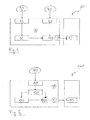
- the figure 5 shows a schematic view of the proposed electronic control 110 for controlling the pump 160 provided with the drive motor 170.
- the pump comprising the drive motor 170 and the proposed electronic control 110 for controlling the motor 170 is also provided.
- the electronic control 110 comprises a control module 120 of the motor 170 of the pump 160.
- the control module 120 converts control data, such as those sent by a boiler of the installation hydraulic, a hydraulic setpoint used to control the motor 170 of the pump 160.
- a hydraulic setpoint used to control the motor 170 of the pump 160.
- the control module 120 drives the engine 170 by a hydraulic setpoint, such as a hydraulic curve setpoint , a flow or pressure.
- the control module 120 can in particular be adapted to communicate bidirectionally.
- the control module can send data to the boiler of the hydraulic system such as the flow rate in the pump, the power consumed by the pump, or any other useful data for the boiler. and can be determined by the pump.
- the conversion of the control data into a hydraulic setpoint takes place according to the parameterization of this module 120.
- the operation of the pump 160 is indeed in particular conditioned by the programming parameters of the pump 160. These programming parameters of the pump 160 are chosen in particular according to the physical characteristics of the pump 160 and the characteristics of the hydraulic installation on the pump 160. which pump 160 is installed.
- the proposed command 110 comprises a parameterization module 130. According to the parameterization data received by the parameterization module 130, this module 130 parameterizes the control module 120, or modifies the parameterization of the control module 120.
- the proposed command 110 comprises an electronic communication connector 140 which receives both the parameterization data and both the control data.
- the control 110 comprises a communication module 150 connected to this connector 140.
- the modules 120, 130, and 150 can be integrated on the same electronic card , the notion of modules being particularly functional and not necessarily physical.
- This communication module 150 is adapted to distribute the setting data and control data, respectively to the parameterization module 130 and to the control module 120.
- the communication module 150 identifies the nature of the data provided.
- Such a method for controlling the motor 170 is also proposed by means of the proposed command 110 and comprising the supply of the data to the communication module 150 and the identification of the nature of these data by the communication module 150.
- 180 data supplied to the communication module 150 are identified as parameter data, the communication module 150 transmits these data to the parameterization module 130 which parameterizes the control module 120 or modifies the parameters of the control module 120.
- the communication module 150 transmits these data to the control module 120, which converts these data into a hydraulic setpoint according to its setting.
- the identification of the nature of the data 180 performed by the communication module 150 allows the proposed electronic control to include only one electronic communication connector with external organs to the pump.
- This single connector is the connector 140 and corresponds to the union of the connectors 45 and 40 previously illustrated in FIG. figure 4 .
- the connector 140 concentrates both the function of the parametering connector and the function of the control connector 40.
- this meeting of the external communication connectors in the only external communication connector 140 makes it possible to make the connector allowing the parameterization of the pump 160 more accessible to the user.
- the parameterization can then notably be envisaged on site, such as when troubleshooting and especially when replacing a pump damaged by a generic pump to set according to the characteristics of the hydraulic system to troubleshoot.
- the use of a single external communication connector as proposed also facilitates the design of the electronic control, including its housing, also designated housing. Even though the connector 140 is the only external communication connector, the proposed electronic control may also include connectors other than communication connectors.
- the command 110 can thus comprise a power transmission connector 149 to the pump motor 170, the transmitted power being controlled by the control module as a function of the received control data, via the hydraulic setpoint.
- the electronic control 110 may also include a power supply connector, similar to the known connector 47 illustrated in FIG. Figures 2 and 3 . According to the illustrated embodiment, since the connector 149 and the power supply connector are not communication connectors, the electronic control 110 does not have an electronic communication connector other than the connector 140. In other words, the control 110 may be devoid of electronic communication connector other than the connector 140 to which the communication module is connected.
- the control module 120 of the proposed electronic control 110 can in particular be adapted to receive control data in the form of pulse width modulation (also referred to as Pulse Width Modulation, abbreviated as PWM).
- the parameterization module 130 can be adapted to receive the parameterization data in the form of a universal asynchronous transceiver signal (signal or protocol also referred to as Universal Asynchronous Receiver Transmitter, abbreviated as UART).
- UART Universal Asynchronous Receiver Transmitter
- the connector 140 is in any case designed to receive both types of data, control and parameterization.
- the connector 140 may in particular be of the PWM type, in particular bidirectional, the UART signals being able to pass through this type of connector.
- the communication module 150 identifies the data 180 as control data to be communicated to the control module 120. This identification can cease upon receipt of a switching signal in the data 180.
- the switching signal corresponds for example to a frequency signal greater than 5000 Hz, which corresponds to the upper limit of the PWM type signals.
- the switching signal may have a frequency greater than or equal to 20000Hz to differentiate well from the control signal frequencies which may be PWM signals. The frequency pitch alone may be sufficient to identify the switching signal.
- the frequency height may be associated with a certain duration of a switching signal, such as greater than or equal to 100 ms.
- the data 180 is identified by the communication module 150 as parameterization data to be transmitted to the parameterization module 130.
- Such an identification may remain for at least a predetermined duration and preferably for a predetermined period of time. after the absence of any signal.
- the communication module 150 identifies new data 180 as control data. This period of absence of received data 180, switching period, can be chosen greater than or equal to 1 minute.
- the pump 160 can be disconnected and then reconnected for the electronic control 110 to recognize the data supplied as control data by default.
- the present invention is not limited to the examples and the embodiment described and shown, but it is capable of many variants.
- the communication module 150 can identify the data 180 as parameterization data to be communicated to the parameterization module 120 and this for a certain predetermined duration, such as of the order of one minute. .
- This initial period of temporary and default identification of the data 180 as parameterization data makes it possible to simplify the communication module 150 which may not discriminate any differences in frequencies between control data and parameterization data.
Abstract
L'invention se rapporte à une commande électronique (110) pour une pompe de circulation (160) comprenant un moteur d'entrainement (170), la commande comprenant : un module de contrôle (120) du moteur d'entraînement (170) de la pompe de circulation ; un module de paramétrage (130) du module de contrôle ; un connecteur (140) de communication électrique ; un module de communication (150) relié, d'une part, au connecteur et, d'autre part, aux modules de paramétrage et de contrôle, le module de communication étant adapté à distribuer des données de paramétrage et des données de contrôle, reçues par le connecteur, respectivement au module de paramétrage et au module de contrôle. L'invention se rapporte également à une pompe de circulation et à un procédé de contrôle d'un moteur d'une pompe de circulation.The invention relates to an electronic control (110) for a circulation pump (160) comprising a drive motor (170), the control comprising: a control module (120) of the drive motor (170) of the circulation pump; a parameterization module (130) of the control module; a connector (140) for electrical communication; a communication module (150) connected, on the one hand, to the connector and, on the other hand, to the parameterization and control modules, the communication module being adapted to distribute parameter data and control data, received by the connector, respectively to the parameterization module and the control module. The invention also relates to a circulation pump and a method for controlling a motor of a circulation pump.
Description
L'invention se rapporte à une commande électronique pour une pompe de circulation. L'invention se rapporte en outre à une pompe de circulation et à un procédé de contrôle d'un moteur de pompe de circulation.The invention relates to an electronic control for a circulation pump. The invention further relates to a circulation pump and a method of controlling a circulation pump motor.
Dans le domaine des installations hydrauliques, il est connu de recourir à une pompe de circulation, également appelé circulateur, pour permettre la circulation d'un fluide dans l'installation hydraulique. De telles pompes sont ainsi présentes dans les installations d'eau chaude sanitaire ou dans les installations de chauffage domestique, qu'il s'agisse de chauffage au fioul, au gaz ou par énergie solaire. De telles installations sont réalisées au domicile de l'utilisateur, directement dans la partie privative du domicile ou dans les parties communes d'une copropriété du domicile de l'utilisateur.In the field of hydraulic installations, it is known to use a circulation pump, also called a circulator, to allow the circulation of a fluid in the hydraulic installation. Such pumps are thus present in domestic hot water installations or in domestic heating installations, whether heating oil, gas or solar energy. Such installations are carried out at the user's home, directly in the private part of the home or in the common areas of a co-ownership of the user's home.
Dans l'état de la technique, pour permettre le contrôle des pompes de circulation, il est connu d'intégrer aux pompes de circulation une commande électronique contrôlant un moteur d'entraînement de la pompe. La
La commande électronique 10 comprend en outre des connecteurs de communication électronique avec des organes externes à la pompe. Ces connecteurs de communication électronique avec des organes externes à la pompe comprennent d'une part le connecteur 40 de communication de pilotage de la pompe. Ce connecteur 40 est prévu pour recevoir un câble de connexion 82, tel qu'illustré en
En référence à la
A la différence du connecteur de pilotage 40 de la pompe 60, le connecteur de paramétrage 45 n'est pas visible sur les
Il existe donc un besoin pour une commande électronique d'une pompe de circulation dont l'accès au paramétrage est simplifié.There is therefore a need for an electronic control of a circulation pump whose access to the parameterization is simplified.
A cette fin, la présente invention propose une commande électronique pour une pompe de circulation comprenant un moteur d'entrainement, la commande comprenant :
- un module de contrôle du moteur d'entraînement de la pompe de circulation ;
- un module de paramétrage du module de contrôle ;
- un connecteur de communication électrique ;
- un module de communication relié, d'une part, au connecteur et, d'autre part, aux modules de paramétrage et de contrôle, le module de communication étant adapté à distribuer des données de paramétrage et des données de contrôle, reçues par le connecteur, respectivement au module de paramétrage et au module de contrôle.
- a control module of the drive motor of the circulation pump;
- a parameterization module of the control module;
- an electrical communication connector;
- a communication module connected, on the one hand, to the connector and, on the other hand, to the parameterization and control modules, the communication module being adapted to distribute parameterization data and control data, received by the connector , respectively to the parameterization module and the control module.
Selon une variante, la commande électronique est dépourvue de connecteur de communication électronique autre que le connecteur auquel est relié le module de communication.According to a variant, the electronic control is devoid of an electronic communication connector other than the connector to which the communication module is connected.
Selon une variante, le module de contrôle est paramétré par le module de paramétrage pour convertir les données de contrôle distribuées par le module de communication en une consigne hydraulique de pilotage du moteur d'entrainement de la pompe.According to one variant, the control module is parameterized by the parameterization module for converting the control data distributed by the communication module into a hydraulic setpoint for controlling the driving motor of the pump.
Selon une variante, le module de contrôle est adapté à recevoir des données de contrôle, et, de préférence, à émettre des données de retour sous forme de débit, puissance et pression.According to one variant, the control module is adapted to receive control data, and, preferably, to transmit return data in the form of flow, power and pressure.
Selon une variante, le module de contrôle est adapté à recevoir les données de contrôle sous la forme de modulation de largeur d'impulsion.According to one variant, the control module is adapted to receive the control data in the form of pulse width modulation.
Selon une variante, le module de paramétrage est adapté à recevoir les données de paramétrage sous la forme d'un signal émetteur-récepteur asynchrone universel.According to one variant, the parameterization module is adapted to receive the parameterization data in the form of a universal asynchronous transceiver signal.
Selon une variante, le module de communication est adapté à identifier par défaut les données reçues comme des données de contrôle, et à identifier après la réception d'un signal de commutation les données reçues comme des données de paramétrage, au moins pendant un laps de temps déterminé.According to one variant, the communication module is adapted to identify, by default, the received data as control data, and to identify, after reception of a switching signal, the received data as parameter data, at least for a period of determined time.
Selon une variante, le signal de commutation est un signal de fréquence supérieure à 5000 Hz, de préférence supérieure ou égale à 20000Hz, et de durée supérieure ou égale à 100 ms.According to one variant, the switching signal is a signal of frequency greater than 5000 Hz, preferably greater than or equal to 20000 Hz, and of duration greater than or equal to 100 ms.
Selon une variante, le module de communication est adaptée à identifier les données comme des données de paramétrage suite au signal de commutation et jusqu'à l'absence de réception de tout signal pendant un laps de temps prédéterminé, de préférence supérieur ou égale à 1 minute.According to one variant, the communication module is adapted to identify the data as parameterization data following the switching signal and until no signal has been received for a predetermined period of time, preferably greater than or equal to 1 minute.
L'invention propose aussi une pompe de circulation d'une installation hydraulique domestique, ladite pompe comprenant un moteur d'entraînement et la commande électronique précédente adaptée à contrôler le moteur d'entraînement.The invention also proposes a circulation pump for a domestic hydraulic installation, said pump comprising a drive motor and the preceding electronic control adapted to control the drive motor.
L'invention propose encore un procédé de contrôle d'un moteur d'entraînement de pompe de circulation à l'aide de la commande électronique précédente, le procédé comprenant :
- la fourniture au module de communication de la commande électronique des données de paramétrage ou de contrôle par l'intermédiaire du connecteur de la commande électronique ;
- l'identification par le module de communication de la nature des données fournies entre des données de paramétrage ou des données de contrôle ;
- le paramétrage du module de contrôle à l'aide du module de paramétrage lorsque les données fournies au module de communication sont identifiées comme étant des données de paramétrage ; ou
- le contrôle du moteur d'entraînement à l'aide du module de contrôle lorsque les données fournies au module de communication sont identifiées comme étant des données de contrôle.
- supplying to the communication module of the electronic control parameter or control data via the connector of the electronic control;
- the identification by the communication module of the nature of the data provided between parameterization data or control data;
- the parameterization of the control module using the parameterization module when the data supplied to the communication module are identified as parameterization data; or
- control of the drive motor using the control module when the data supplied to the communication module is identified as control data.
D'autres caractéristiques et avantages de l'invention apparaîtront à la lecture de la description qui suit d'un mode de réalisation préféré de l'invention, donnée à titre d'exemple et en référence aux dessins annexés.
- La
figure 1 montre une vue en perspective d'une pompe connue comprenant un commande électronique. - La
figure 2 montre une vue arrière de la pompe de lafigure 1 , avec un câble de connexion déconnecté. - La
figure 3 montre la pompe desfigures 1 et 2 avec le câble de connexion connecté. - La
figure 4 montre, en vue schématique, la pompe desfigures 1 à 3 . - La
figure 5 représente, de façon schématique, une pompe comprenant une commande électronique proposée.
- The
figure 1 shows a perspective view of a known pump comprising an electronic control. - The
figure 2 shows a rear view of the pump thefigure 1 , with a disconnected connection cable. - The
figure 3 shows the pumpFigures 1 and 2 with the connection cable connected. - The
figure 4 shows, schematically, the pump ofFigures 1 to 3 . - The
figure 5 schematically represents a pump comprising a proposed electronic control.
Il est proposé une commande électronique pour une pompe de circulation. En particulier, la commande électronique proposée est prévue pour une pompe de circulation, également désignée par l'expression "circulateur hydraulique", d'une installation hydraulique domestique d'eau chaude sanitaire ou de chauffage, c'est-à-dire notamment les installations hydrauliques installées au domicile de l'usager. Une telle installation hydraulique peut ainsi correspondre à une installation d'eau chaude sanitaire ou de chauffage domestique de tout bâtiment, tel qu'un immeuble d'habitation ou de bureaux et notamment tel qu'une usine. Cette installation hydraulique ne correspond toutefois pas à une installation hydraulique industrielle. Ainsi, la puissance hydraulique utile nominale du circulateur de l'installation à dépanner peut être comprise entre 1 et 2500 W.It is proposed an electronic control for a circulation pump. In particular, the proposed electronic control is provided for a circulation pump, also designated by the term "hydraulic circulator", of a domestic hydraulic system for domestic hot water or for heating, that is to say in particular the hydraulic installations installed in the user's home. Such a hydraulic installation can thus correspond to a domestic hot water or heating system of any building, such as a residential building or office and especially such as a factory. This hydraulic installation does not, however, correspond to an industrial hydraulic installation. Thus, the nominal hydraulic power of the pump of the installation to be serviced can be between 1 and 2500 W.
La pompe de circulation à commander correspond à la pompe de circulation 60 illustrée en
En référence à la
Le fonctionnement de la pompe 160 est en effet notamment conditionné par les paramètres de programmation de la pompe 160. Ces paramètres de programmation de la pompe 160 sont notamment choisis en fonction des caractéristiques physiques de la pompe 160 et des caractéristiques de l'installation hydraulique sur laquelle la pompe 160 est installée. Pour permettre la modification du paramétrage en fonction de ces différents facteurs, la commande proposée 110 comprend un module de paramétrage 130. En fonction des données de paramétrage reçues par le module de paramétrage 130, ce module 130 paramètre le module de contrôle 120, ou modifie le paramétrage du module de contrôle 120.The operation of the pump 160 is indeed in particular conditioned by the programming parameters of the pump 160. These programming parameters of the pump 160 are chosen in particular according to the physical characteristics of the pump 160 and the characteristics of the hydraulic installation on the pump 160. which pump 160 is installed. To allow the modification of the parameterization according to these various factors, the proposed
Toutefois à la différence de la commande connue 10, la commande proposée 110 comprend un connecteur 140 de communication électronique qui reçoit à la fois les données de paramétrage et à la fois les données de contrôle. Pour permettre la distribution de ces données 180, la commande 110 comprend un module de communication 150 relié à ce connecteur 140. Pour des questions d'architecture et de compacité, les modules 120, 130, et 150 peuvent être intégrés sur une même carte électronique, la notion de modules étant notamment fonctionnelle et non nécessairement physique.However, unlike the known
Ce module de communication 150 est adapté à distribuer les données de paramétrages et des données de contrôle, respectivement au module de paramétrage 130 et au module de contrôle 120. En d'autres termes, après la fourniture au module de communication 150 de données par l'intermédiaire du connecteur 140, le module de communication 150 identifie la nature des données fournies. Est également proposé un tel procédé de contrôle du moteur 170 à l'aide de la commande 110 proposée et comprenant la fourniture des données au module de communication 150 et l'identification de la nature de ces données par le module de communication 150. Lorsque les données 180 fournies au module de communication 150 sont identifiées comme étant des données de paramétrage, le module de communication 150 transmet ces données au module de paramétrage 130 qui paramètre le module de contrôle 120 ou modifie les paramètres du module de contrôle 120. Lorsque les données 180 fournies au module de communication 150 sont identifiées comme étant des données de contrôle, le module de communication 150 transmet ces données au module de contrôle 120, qui convertit ces données en une consigne hydraulique en fonction de son paramétrage.This
L'identification de la nature des données 180 effectuée par le module de communication 150 permet à la commande électronique proposée de ne comprendre qu'un seul connecteur de communication électronique avec des organes externes à la pompe. Cet unique connecteur est le connecteur 140 et correspond à la réunion des connecteurs 45 et 40 précédemment illustrées en
En définitive, cette réunion des connecteurs de communication externe en le seul connecteur de communication externe 140 permet de rendre plus accessible à l'usager le connecteur permettant le paramétrage de la pompe 160. Le paramétrage peut alors notamment être envisagé sur site, tel que lors d'un dépannage et notamment lors du remplacement d'une pompe endommagé par une pompe générique à paramétrer en fonction des caractéristiques de l'installation hydraulique à dépanner. L'utilisation d'un seul connecteur de communication externe tel que proposé permet par ailleurs de faciliter la conception de la commande électronique, et notamment de son boîtier, également désigné carter. Même si le connecteur 140 est le seul connecteur de communication externe, la commande électronique proposée peut aussi comprendre des connecteurs autres que des connecteurs de communication. La commande 110 peut ainsi comprendre un connecteur 149 de transmission de puissance au moteur 170 de la pompe, la puissance transmise étant contrôlée par le module de contrôle en fonction des données de contrôle reçues, par l'intermédiaire de la consigne hydraulique. La commande électronique 110 peut aussi comprendre un connecteur d'alimentation électrique, similaire au connecteur connu 47 illustré en
Le module de contrôle 120 de la commande électronique proposée 110 peut notamment être adaptée à recevoir des données de contrôle sous la forme de modulation de largeur d'impulsion (également désignée par l'expression anglaise Pulse Width Modulation, abrégée en PWM). Le module de paramétrage 130 peut lui être adapté à recevoir les données de paramétrage sous la forme d'un signal émetteur-récepteur asynchrone universel (signal ou protocole également désigné par l'expression anglaise Universal Asynchronous Receiver Transmitter, abrégé en UART). Indépendamment du type de connecteur de communication externe 140, et de la forme des données de contrôles, le connecteur 140 est en tous les cas prévu pour recevoir les deux types de données, de contrôle et de paramétrage. A cette fin, le connecteur 140 peut notamment être du type PWM, notamment bidirectionnel, les signaux UART pouvant transiter par ce type de connecteur.The
Pour distinguer la nature des signaux reçus par le module de communication 150 via le connecteur 140, différentes méthodes d'identification peuvent être envisagées. En particulier il est préféré que par défaut les données reçues par le module de communication soient identifiées comme des données de contrôle. Ainsi à la mise sous tension de la pompe, le module de communication 150 identifie les données 180 comme des données de contrôle à communiquer au module de contrôle 120. Cette identification peut cesser à la réception d'un signal de commutation dans les données 180. Le signal de commutation correspond par exemple à un signal de fréquence supérieure à 5000 Hz, qui correspond à la limite haute des signaux de type PWM. De préférence le signal de commutation peut présenter une fréquence supérieure ou égale à 20000Hz pour bien se différencier des fréquences de signaux de contrôle qui peuvent être de signaux PWM. La hauteur de fréquence seule peut suffire à identifier le signal de commutation. Néanmoins pour des questions de stabilité il peut être préférable, d'associer la hauteur de fréquence à une certaine durée de signal de commutation, telle supérieure ou égale à 100 ms. A la suite du signal de commutation, les données 180 sont identifiées par le module de communication 150 comme des données de paramétrage à transmettre au module de paramétrage 130. Une telle identification peut demeurer au moins pour une durée déterminée et de préférence pour une durée déterminée après l'absence de tout signal. Ainsi, selon cette dernière variante, suite à une absence de données 180 reçues par le module de communication 150 pendant une certaine période déterminée, le module de communication 150 identifie de nouvelles données 180 comme des données de contrôle. Cette période d'absence de données 180 reçues, période de commutation, peut être choisie supérieure ou égale à 1 minute. Avec ou sans période de commutation prévue, la pompe 160 peut être débranchée puis rebranchée pour que la commande électronique 110 identifie interprète de nouveau par défaut les données fournies comme étant des données de contrôle.In order to distinguish the nature of the signals received by the
Bien entendu, la présente invention n'est pas limitée aux exemples et au mode de réalisation décrits et représentés, mais elle est susceptible de nombreuses variantes. Notamment, à la mise sous tension de la pompe, le module de communication 150 peut identifier les données 180 comme des données de paramétrage à communiquer au module de paramétrage 120 et ce pendant une certaine durée prédéterminée, tel que de l'ordre de la minute. Cette période initiale d'identification temporaire et par défaut des données 180 comme des données de paramétrage, permet de simplifier le module de communication 150 qui peut ne pas discriminer les éventuelles différences de fréquences entre données de contrôle et de paramétrage.Of course, the present invention is not limited to the examples and the embodiment described and shown, but it is capable of many variants. In particular, when the pump is turned on, the
Claims (10)
Applications Claiming Priority (1)
| Application Number | Priority Date | Filing Date | Title |
|---|---|---|---|
| FR1363563A FR3015587B1 (en) | 2013-12-24 | 2013-12-24 | ELECTRONIC CONTROL FOR A CIRCULATION PUMP, CIRCULATION PUMP AND CORRESPONDING METHOD |
Publications (2)
| Publication Number | Publication Date |
|---|---|
| EP2889708A1 true EP2889708A1 (en) | 2015-07-01 |
| EP2889708B1 EP2889708B1 (en) | 2019-07-10 |
Family
ID=50473494
Family Applications (1)
| Application Number | Title | Priority Date | Filing Date |
|---|---|---|---|
| EP14200222.9A Active EP2889708B1 (en) | 2013-12-24 | 2014-12-23 | Electronic control for a circulation pump, circulation pump and corresponding method |
Country Status (2)
| Country | Link |
|---|---|
| EP (1) | EP2889708B1 (en) |
| FR (1) | FR3015587B1 (en) |
Families Citing this family (1)
| Publication number | Priority date | Publication date | Assignee | Title |
|---|---|---|---|---|
| CN105545763B (en) * | 2015-12-13 | 2017-07-04 | 渤海大学 | Pressure of supply water tank remote control and control method |
Citations (2)
| Publication number | Priority date | Publication date | Assignee | Title |
|---|---|---|---|---|
| FR2815147A1 (en) * | 2000-10-09 | 2002-04-12 | A F C A | control device of means of drive or actuation |
| EP2573403A1 (en) * | 2011-09-20 | 2013-03-27 | Grundfos Holding A/S | Pump |
Family Cites Families (1)
| Publication number | Priority date | Publication date | Assignee | Title |
|---|---|---|---|---|
| PL2610500T3 (en) * | 2011-12-27 | 2016-03-31 | Grundfos Holding As | Pump power unit |
-
2013
- 2013-12-24 FR FR1363563A patent/FR3015587B1/en active Active
-
2014
- 2014-12-23 EP EP14200222.9A patent/EP2889708B1/en active Active
Patent Citations (2)
| Publication number | Priority date | Publication date | Assignee | Title |
|---|---|---|---|---|
| FR2815147A1 (en) * | 2000-10-09 | 2002-04-12 | A F C A | control device of means of drive or actuation |
| EP2573403A1 (en) * | 2011-09-20 | 2013-03-27 | Grundfos Holding A/S | Pump |
Non-Patent Citations (1)
| Title |
|---|
| GILSON: "333 and 334 Pumps User's Guide", 1 February 2000 (2000-02-01), XP055144342, Retrieved from the Internet <URL:http://www.gilson.com/resources/333334_prepscale_hplc_pumps_users_guide.pdf> [retrieved on 20141003] * |
Also Published As
| Publication number | Publication date |
|---|---|
| FR3015587A1 (en) | 2015-06-26 |
| FR3015587B1 (en) | 2019-05-31 |
| EP2889708B1 (en) | 2019-07-10 |
Similar Documents
| Publication | Publication Date | Title |
|---|---|---|
| EP1844230B1 (en) | Method for operating a motor vehicle starter-generator | |
| US7900724B2 (en) | Hybrid drive for hydraulic power | |
| WO2004058530A3 (en) | Control device of hybrid drive unit | |
| WO2007037974A3 (en) | Power control system and method | |
| PL1776251T3 (en) | Start and operation sequences for hybrid motor vehicles | |
| EP1353075A3 (en) | Starting device for a consumer, such as a camshaft adjuster, automatic gearbox and suchlike, of a vehicle, especially a motor vehicle | |
| TW200724413A (en) | Hybrid power system for vehicle | |
| US20150175022A1 (en) | Pto driven dc generator for electric vehicle charging | |
| EP2889708B1 (en) | Electronic control for a circulation pump, circulation pump and corresponding method | |
| US8950446B2 (en) | Geneset fuel transfer system and method | |
| CN105914553B (en) | Intelligent Recognition revolving multipurpose type socket | |
| FR2944071A3 (en) | Installation for recovering and managing wind power provided by Darrieus vertical axis wind pump, has control circuit receiving instructions to control clutch of pump, bidirectional connector and disengageable connectors | |
| EP2889488B1 (en) | Method for servicing a household circulation pump installation | |
| US20080202476A1 (en) | Fuel pump speed control system | |
| US20040187620A1 (en) | Low power, high torque actuator retention | |
| CA2925452C (en) | Managing the control of an electrical device controllable by infrared control signals | |
| EP1498643A3 (en) | Hydraulic transmission control system and method for vehicle having automatic engine stop/restart function | |
| KR101490914B1 (en) | Oil pump system for hybrid vehicle and control method thereof | |
| US10119610B2 (en) | Method for controlling line pressure of automatic transmission | |
| GB2315132A (en) | Limiting engine torque during fault in automatic transmission. | |
| KR200484893Y1 (en) | cargo crain | |
| JP5057766B2 (en) | Photovoltaic power generation system and storage device | |
| EP2541732B1 (en) | Device and method for managing an electric facility indicating the price | |
| KR20160118632A (en) | System and method for automatic charging battery of construction equipment on key off state | |
| CN210466123U (en) | Engine oil seal control system based on PLC |
Legal Events
| Date | Code | Title | Description |
|---|---|---|---|
| PUAI | Public reference made under article 153(3) epc to a published international application that has entered the european phase |
Free format text: ORIGINAL CODE: 0009012 |
|
| 17P | Request for examination filed |
Effective date: 20141223 |
|
| AK | Designated contracting states |
Kind code of ref document: A1 Designated state(s): AL AT BE BG CH CY CZ DE DK EE ES FI FR GB GR HR HU IE IS IT LI LT LU LV MC MK MT NL NO PL PT RO RS SE SI SK SM TR |
|
| AX | Request for extension of the european patent |
Extension state: BA ME |
|
| R17P | Request for examination filed (corrected) |
Effective date: 20160104 |
|
| RBV | Designated contracting states (corrected) |
Designated state(s): AL AT BE BG CH CY CZ DE DK EE ES FI FR GB GR HR HU IE IS IT LI LT LU LV MC MK MT NL NO PL PT RO RS SE SI SK SM TR |
|
| STAA | Information on the status of an ep patent application or granted ep patent |
Free format text: STATUS: EXAMINATION IS IN PROGRESS |
|
| 17Q | First examination report despatched |
Effective date: 20170119 |
|
| GRAP | Despatch of communication of intention to grant a patent |
Free format text: ORIGINAL CODE: EPIDOSNIGR1 |
|
| STAA | Information on the status of an ep patent application or granted ep patent |
Free format text: STATUS: GRANT OF PATENT IS INTENDED |
|
| INTG | Intention to grant announced |
Effective date: 20190204 |
|
| GRAS | Grant fee paid |
Free format text: ORIGINAL CODE: EPIDOSNIGR3 |
|
| GRAA | (expected) grant |
Free format text: ORIGINAL CODE: 0009210 |
|
| STAA | Information on the status of an ep patent application or granted ep patent |
Free format text: STATUS: THE PATENT HAS BEEN GRANTED |
|
| AK | Designated contracting states |
Kind code of ref document: B1 Designated state(s): AL AT BE BG CH CY CZ DE DK EE ES FI FR GB GR HR HU IE IS IT LI LT LU LV MC MK MT NL NO PL PT RO RS SE SI SK SM TR |
|
| REG | Reference to a national code |
Ref country code: GB Ref legal event code: FG4D Free format text: NOT ENGLISH |
|
| REG | Reference to a national code |
Ref country code: CH Ref legal event code: EP Ref country code: AT Ref legal event code: REF Ref document number: 1154223 Country of ref document: AT Kind code of ref document: T Effective date: 20190715 |
|
| REG | Reference to a national code |
Ref country code: DE Ref legal event code: R096 Ref document number: 602014049764 Country of ref document: DE |
|
| REG | Reference to a national code |
Ref country code: IE Ref legal event code: FG4D Free format text: LANGUAGE OF EP DOCUMENT: FRENCH |
|
| REG | Reference to a national code |
Ref country code: NL Ref legal event code: MP Effective date: 20190710 |
|
| REG | Reference to a national code |
Ref country code: LT Ref legal event code: MG4D |
|
| REG | Reference to a national code |
Ref country code: AT Ref legal event code: MK05 Ref document number: 1154223 Country of ref document: AT Kind code of ref document: T Effective date: 20190710 |
|
| PG25 | Lapsed in a contracting state [announced via postgrant information from national office to epo] |
Ref country code: SE Free format text: LAPSE BECAUSE OF FAILURE TO SUBMIT A TRANSLATION OF THE DESCRIPTION OR TO PAY THE FEE WITHIN THE PRESCRIBED TIME-LIMIT Effective date: 20190710 Ref country code: BG Free format text: LAPSE BECAUSE OF FAILURE TO SUBMIT A TRANSLATION OF THE DESCRIPTION OR TO PAY THE FEE WITHIN THE PRESCRIBED TIME-LIMIT Effective date: 20191010 Ref country code: NO Free format text: LAPSE BECAUSE OF FAILURE TO SUBMIT A TRANSLATION OF THE DESCRIPTION OR TO PAY THE FEE WITHIN THE PRESCRIBED TIME-LIMIT Effective date: 20191010 Ref country code: AT Free format text: LAPSE BECAUSE OF FAILURE TO SUBMIT A TRANSLATION OF THE DESCRIPTION OR TO PAY THE FEE WITHIN THE PRESCRIBED TIME-LIMIT Effective date: 20190710 Ref country code: NL Free format text: LAPSE BECAUSE OF FAILURE TO SUBMIT A TRANSLATION OF THE DESCRIPTION OR TO PAY THE FEE WITHIN THE PRESCRIBED TIME-LIMIT Effective date: 20190710 Ref country code: LT Free format text: LAPSE BECAUSE OF FAILURE TO SUBMIT A TRANSLATION OF THE DESCRIPTION OR TO PAY THE FEE WITHIN THE PRESCRIBED TIME-LIMIT Effective date: 20190710 Ref country code: PT Free format text: LAPSE BECAUSE OF FAILURE TO SUBMIT A TRANSLATION OF THE DESCRIPTION OR TO PAY THE FEE WITHIN THE PRESCRIBED TIME-LIMIT Effective date: 20191111 Ref country code: FI Free format text: LAPSE BECAUSE OF FAILURE TO SUBMIT A TRANSLATION OF THE DESCRIPTION OR TO PAY THE FEE WITHIN THE PRESCRIBED TIME-LIMIT Effective date: 20190710 Ref country code: HR Free format text: LAPSE BECAUSE OF FAILURE TO SUBMIT A TRANSLATION OF THE DESCRIPTION OR TO PAY THE FEE WITHIN THE PRESCRIBED TIME-LIMIT Effective date: 20190710 |
|
| PG25 | Lapsed in a contracting state [announced via postgrant information from national office to epo] |
Ref country code: LV Free format text: LAPSE BECAUSE OF FAILURE TO SUBMIT A TRANSLATION OF THE DESCRIPTION OR TO PAY THE FEE WITHIN THE PRESCRIBED TIME-LIMIT Effective date: 20190710 Ref country code: GR Free format text: LAPSE BECAUSE OF FAILURE TO SUBMIT A TRANSLATION OF THE DESCRIPTION OR TO PAY THE FEE WITHIN THE PRESCRIBED TIME-LIMIT Effective date: 20191011 Ref country code: ES Free format text: LAPSE BECAUSE OF FAILURE TO SUBMIT A TRANSLATION OF THE DESCRIPTION OR TO PAY THE FEE WITHIN THE PRESCRIBED TIME-LIMIT Effective date: 20190710 Ref country code: AL Free format text: LAPSE BECAUSE OF FAILURE TO SUBMIT A TRANSLATION OF THE DESCRIPTION OR TO PAY THE FEE WITHIN THE PRESCRIBED TIME-LIMIT Effective date: 20190710 Ref country code: IS Free format text: LAPSE BECAUSE OF FAILURE TO SUBMIT A TRANSLATION OF THE DESCRIPTION OR TO PAY THE FEE WITHIN THE PRESCRIBED TIME-LIMIT Effective date: 20191110 Ref country code: RS Free format text: LAPSE BECAUSE OF FAILURE TO SUBMIT A TRANSLATION OF THE DESCRIPTION OR TO PAY THE FEE WITHIN THE PRESCRIBED TIME-LIMIT Effective date: 20190710 |
|
| PG25 | Lapsed in a contracting state [announced via postgrant information from national office to epo] |
Ref country code: TR Free format text: LAPSE BECAUSE OF FAILURE TO SUBMIT A TRANSLATION OF THE DESCRIPTION OR TO PAY THE FEE WITHIN THE PRESCRIBED TIME-LIMIT Effective date: 20190710 |
|
| PG25 | Lapsed in a contracting state [announced via postgrant information from national office to epo] |
Ref country code: DK Free format text: LAPSE BECAUSE OF FAILURE TO SUBMIT A TRANSLATION OF THE DESCRIPTION OR TO PAY THE FEE WITHIN THE PRESCRIBED TIME-LIMIT Effective date: 20190710 Ref country code: IT Free format text: LAPSE BECAUSE OF FAILURE TO SUBMIT A TRANSLATION OF THE DESCRIPTION OR TO PAY THE FEE WITHIN THE PRESCRIBED TIME-LIMIT Effective date: 20190710 Ref country code: EE Free format text: LAPSE BECAUSE OF FAILURE TO SUBMIT A TRANSLATION OF THE DESCRIPTION OR TO PAY THE FEE WITHIN THE PRESCRIBED TIME-LIMIT Effective date: 20190710 Ref country code: PL Free format text: LAPSE BECAUSE OF FAILURE TO SUBMIT A TRANSLATION OF THE DESCRIPTION OR TO PAY THE FEE WITHIN THE PRESCRIBED TIME-LIMIT Effective date: 20190710 Ref country code: RO Free format text: LAPSE BECAUSE OF FAILURE TO SUBMIT A TRANSLATION OF THE DESCRIPTION OR TO PAY THE FEE WITHIN THE PRESCRIBED TIME-LIMIT Effective date: 20190710 |
|
| PG25 | Lapsed in a contracting state [announced via postgrant information from national office to epo] |
Ref country code: CZ Free format text: LAPSE BECAUSE OF FAILURE TO SUBMIT A TRANSLATION OF THE DESCRIPTION OR TO PAY THE FEE WITHIN THE PRESCRIBED TIME-LIMIT Effective date: 20190710 Ref country code: SK Free format text: LAPSE BECAUSE OF FAILURE TO SUBMIT A TRANSLATION OF THE DESCRIPTION OR TO PAY THE FEE WITHIN THE PRESCRIBED TIME-LIMIT Effective date: 20190710 Ref country code: SM Free format text: LAPSE BECAUSE OF FAILURE TO SUBMIT A TRANSLATION OF THE DESCRIPTION OR TO PAY THE FEE WITHIN THE PRESCRIBED TIME-LIMIT Effective date: 20190710 Ref country code: IS Free format text: LAPSE BECAUSE OF FAILURE TO SUBMIT A TRANSLATION OF THE DESCRIPTION OR TO PAY THE FEE WITHIN THE PRESCRIBED TIME-LIMIT Effective date: 20200224 |
|
| REG | Reference to a national code |
Ref country code: DE Ref legal event code: R097 Ref document number: 602014049764 Country of ref document: DE |
|
| PLBE | No opposition filed within time limit |
Free format text: ORIGINAL CODE: 0009261 |
|
| STAA | Information on the status of an ep patent application or granted ep patent |
Free format text: STATUS: NO OPPOSITION FILED WITHIN TIME LIMIT |
|
| PG2D | Information on lapse in contracting state deleted |
Ref country code: IS |
|
| REG | Reference to a national code |
Ref country code: CH Ref legal event code: PL |
|
| 26N | No opposition filed |
Effective date: 20200603 |
|
| REG | Reference to a national code |
Ref country code: BE Ref legal event code: MM Effective date: 20191231 |
|
| PG25 | Lapsed in a contracting state [announced via postgrant information from national office to epo] |
Ref country code: SI Free format text: LAPSE BECAUSE OF FAILURE TO SUBMIT A TRANSLATION OF THE DESCRIPTION OR TO PAY THE FEE WITHIN THE PRESCRIBED TIME-LIMIT Effective date: 20190710 Ref country code: MC Free format text: LAPSE BECAUSE OF FAILURE TO SUBMIT A TRANSLATION OF THE DESCRIPTION OR TO PAY THE FEE WITHIN THE PRESCRIBED TIME-LIMIT Effective date: 20190710 |
|
| GBPC | Gb: european patent ceased through non-payment of renewal fee |
Effective date: 20191223 |
|
| PG25 | Lapsed in a contracting state [announced via postgrant information from national office to epo] |
Ref country code: LU Free format text: LAPSE BECAUSE OF NON-PAYMENT OF DUE FEES Effective date: 20191223 Ref country code: IE Free format text: LAPSE BECAUSE OF NON-PAYMENT OF DUE FEES Effective date: 20191223 Ref country code: GB Free format text: LAPSE BECAUSE OF NON-PAYMENT OF DUE FEES Effective date: 20191223 |
|
| PG25 | Lapsed in a contracting state [announced via postgrant information from national office to epo] |
Ref country code: BE Free format text: LAPSE BECAUSE OF NON-PAYMENT OF DUE FEES Effective date: 20191231 Ref country code: LI Free format text: LAPSE BECAUSE OF NON-PAYMENT OF DUE FEES Effective date: 20191231 Ref country code: CH Free format text: LAPSE BECAUSE OF NON-PAYMENT OF DUE FEES Effective date: 20191231 |
|
| PG25 | Lapsed in a contracting state [announced via postgrant information from national office to epo] |
Ref country code: CY Free format text: LAPSE BECAUSE OF FAILURE TO SUBMIT A TRANSLATION OF THE DESCRIPTION OR TO PAY THE FEE WITHIN THE PRESCRIBED TIME-LIMIT Effective date: 20190710 |
|
| PG25 | Lapsed in a contracting state [announced via postgrant information from national office to epo] |
Ref country code: HU Free format text: LAPSE BECAUSE OF FAILURE TO SUBMIT A TRANSLATION OF THE DESCRIPTION OR TO PAY THE FEE WITHIN THE PRESCRIBED TIME-LIMIT; INVALID AB INITIO Effective date: 20141223 Ref country code: MT Free format text: LAPSE BECAUSE OF FAILURE TO SUBMIT A TRANSLATION OF THE DESCRIPTION OR TO PAY THE FEE WITHIN THE PRESCRIBED TIME-LIMIT Effective date: 20190710 |
|
| PG25 | Lapsed in a contracting state [announced via postgrant information from national office to epo] |
Ref country code: MK Free format text: LAPSE BECAUSE OF FAILURE TO SUBMIT A TRANSLATION OF THE DESCRIPTION OR TO PAY THE FEE WITHIN THE PRESCRIBED TIME-LIMIT Effective date: 20190710 |
|
| PGFP | Annual fee paid to national office [announced via postgrant information from national office to epo] |
Ref country code: DE Payment date: 20221213 Year of fee payment: 9 |
|
| PGFP | Annual fee paid to national office [announced via postgrant information from national office to epo] |
Ref country code: FR Payment date: 20231227 Year of fee payment: 10 |