EP2573231A2 - Spinning machine - Google Patents
Spinning machine Download PDFInfo
- Publication number
- EP2573231A2 EP2573231A2 EP12183045A EP12183045A EP2573231A2 EP 2573231 A2 EP2573231 A2 EP 2573231A2 EP 12183045 A EP12183045 A EP 12183045A EP 12183045 A EP12183045 A EP 12183045A EP 2573231 A2 EP2573231 A2 EP 2573231A2
- Authority
- EP
- European Patent Office
- Prior art keywords
- package
- section
- reverse
- spinning
- spun yarn
- Prior art date
- Legal status (The legal status is an assumption and is not a legal conclusion. Google has not performed a legal analysis and makes no representation as to the accuracy of the status listed.)
- Granted
Links
Images


Classifications
-
- D—TEXTILES; PAPER
- D01—NATURAL OR MAN-MADE THREADS OR FIBRES; SPINNING
- D01H—SPINNING OR TWISTING
- D01H5/00—Drafting machines or arrangements ; Threading of roving into drafting machine
- D01H5/18—Drafting machines or arrangements without fallers or like pinned bars
- D01H5/70—Constructional features of drafting elements
- D01H5/86—Aprons; Apron supports; Apron tensioning arrangements
- D01H5/88—Cradles; Tensors
-
- B—PERFORMING OPERATIONS; TRANSPORTING
- B65—CONVEYING; PACKING; STORING; HANDLING THIN OR FILAMENTARY MATERIAL
- B65H—HANDLING THIN OR FILAMENTARY MATERIAL, e.g. SHEETS, WEBS, CABLES
- B65H67/00—Replacing or removing cores, receptacles, or completed packages at paying-out, winding, or depositing stations
- B65H67/08—Automatic end-finding and material-interconnecting arrangements
- B65H67/081—Automatic end-finding and material-interconnecting arrangements acting after interruption of the winding process, e.g. yarn breakage, yarn cut or package replacement
- B65H67/085—Automatic end-finding and material-interconnecting arrangements acting after interruption of the winding process, e.g. yarn breakage, yarn cut or package replacement end-finding at the take-up package, e.g. by suction and reverse package rotation
-
- B—PERFORMING OPERATIONS; TRANSPORTING
- B65—CONVEYING; PACKING; STORING; HANDLING THIN OR FILAMENTARY MATERIAL
- B65H—HANDLING THIN OR FILAMENTARY MATERIAL, e.g. SHEETS, WEBS, CABLES
- B65H2701/00—Handled material; Storage means
- B65H2701/30—Handled filamentary material
- B65H2701/31—Textiles threads or artificial strands of filaments
Definitions
- the present invention relates to a spinning machine.
- the spinning unit includes a winding section adapted to wind a spun yarn to form a package.
- the winding section includes a driving roller adapted to rotate the package in a forward direction, and a cradle adapted to rotatably support the package.
- the spinning machine includes an operation cart adapted to travel to one of the spinning units and perform a yarn joining operation when a continuation of the spun yarn is disconnected in such spinning unit.
- the operation cart includes a braking section adapted to brake rotation of the package, a reverse-rotation roller adapted to rotate the package in an unwinding direction, which is an opposite direction of the winding direction, a guiding section adapted to catch and guide the spun yarn, and a yarn joining section adapted to join yarn ends of the spun yarn.
- the spinning unit swings the cradle when the continuation of the spun yarn is disconnected, and separates the package from the driving roller.
- the operation cart After stopping the rotation of the package by the braking section, the operation cart makes the reverse-rotation roller to contact with the package and rotates the package in the unwinding direction (hereinafter, simply referred to as "reverse rotation").
- the operation cart catches the spun yarn and guides the spun yarn to a predetermined position by the guiding section, and joins the yarn ends of the spun yarn by the yarn joining section.
- the spinning unit swings the cradle again, and makes the package to contact with the driving roller.
- the spinning unit can resume formation of the package through such series of processes.
- the package may reversely rotate unintendedly accompanying movement of the reverse-rotation roller.
- the package may reversely rotate unintendedly and the spun yarn may slacken.
- An object of the present invention is to provide a spinning machine in which a spun yarn does not slacken in a series of processes after formation of a package is interrupted and until the formation of the package is resumed.
- a spinning machine includes a plurality of spinning units, each spinning unit being adapted to wind a spun yarn to form a package.
- the spinning machine includes a driving roller adapted to make contact with the package to rotate the package in a winding direction, a cradle adapted to move the package to a contacting position and a receded position with respect to the driving roller, a reverse-rotation roller adapted to make contact with the package to rotate the package in an unwinding direction that is in an opposite direction of the winding direction, a driving section adapted to make the package and the reverse-rotation roller to contact with or separated from one another, and a control section adapted to control the driving section to separate the reverse-rotation roller and the package immediately before the package reaches the contacting position with respect to the driving roller by the package being moved by the cradle.
- the package Since the package makes contact with the driving roller immediately after the reverse-rotation roller is separated from the package, the package does not reversely rotate unintendedly. Accordingly, the spun yarn can be prevented from slackening.
- the control section is adapted to control the driving section such that a contact pressure of the reverse-rotation roller and the package is substantially constant regardless of an outer diameter of the package. Even if the outer diameter of the package differs, a difference in the contact pressure of the reverse-rotation roller and the package can be reduced. Accordingly, deformation of the package and degradation in quality of the spun yarn wound into the package thus can be prevented.
- the driving section is a pneumatic actuator.
- a timing in which the reverse-rotation roller separates from the package can be controlled at high accuracy. Therefore, since the package makes contact with the driving roller immediately after the reverse-rotation roller is separated from the package, the package does not reversely rotate unintendedly. Accordingly, the spun yarn can be prevented from slackening. Even if the outer diameter of the package differs, the difference in the contact pressure of the reverse-rotation roller and the package can be reduced. Accordingly, the deformation of the package and the degradation in the quality of the spun yarn wound into the package can be prevented.
- the spinning machine further includes an operation cart adapted to travel to one of the spinning units when a continuation of the spun yarn is disconnected in such spinning unit and to perform a yarn joining operation.
- the operation cart includes the reverse-rotation roller, the driving section, a braking section adapted to brake rotation of the package, a guiding section adapted to catch and guide the disconnected spun yarn, and a yarn joining section adapted to join yarn ends of the disconnected spun yarn.
- Each of the spinning units includes a spinning section adapted to twist a fiber bundle by a whirling airflow. Accordingly, production efficiency of the spun yarn in each spinning unit thus can be improved, and production efficiency of the package in the spinning machine can be improved.
- black arrows indicate a travelling direction of an operation cart 20
- white arrows indicate a travelling direction of a doffing cart 30.
- the spinning machine 100 includes a plurality of spinning units 10.
- the spinning machine 100 includes the operation cart 20, the doffing cart 30, and a control section 40.
- the spinning unit 10 is adapted to draft a fiber bundle F and twist the drafted fiber bundle F to produce a spun yarn Y.
- the spinning unit 10 can form a package P by winding the spun yarn Y. A detailed structure of the spinning unit 10 will be described later.
- the operation cart 20 can travel along a rail R1 extending in a direction in which the spinning units 10 are arranged. When a continuation of the spun yarn Y is disconnected in one of the spinning units 10, the operation cart 20 travels to the relevant spinning unit 10 and performs a yarn joining operation. A detailed structure of the operation cart 20 will be described later.
- the doffing cart 30 can travel along a rail R2 extending in a direction in which the spinning units 10 are arranged. When the package P is fully wound in one of the spinning units 10, the doffing cart 30 can travel to the relevant spinning unit 10 and collect the package P. The doffing cart 30 can set a new bobbin B to the spinning unit 10. The doffing cart 30 may perform only an operation of collecting the fully-wound package P. If the collecting of the package P and the setting of the new bobbin B are manually performed by an operator, the doffing cart 30 may be omitted.
- the control section 40 can control each spinning unit 10, the operation cart 20, and the like. For example, when the continuation of the spun yarn Y is disconnected in one of the spinning units 10, the control section 40 controls the relevant spinning unit 10 to interrupt the formation of the package P. After controlling the operation cart 20 to perform the yarn joining operation, the control section 40 controls the spinning unit 10 to resume the formation of the package P.
- black arrows indicate a feeding direction of the fiber bundle F and the spun yarn Y
- a white arrow indicates a rotating direction of the package P.
- the spinning unit 10 includes a sliver supplying section 1, a drafting section 2, a spinning section 3, a defect detecting section 4, a tension stabilizing section 5, and a winding section 6 along the feeding direction of the fiber bundle F and the spun yarn Y.
- the sliver supplying section 1 is adapted to supply the fiber bundle F to the drafting section 2.
- the sliver supplying section 1 includes a sliver case 11 and a sliver guide (not illustrated).
- the fiber bundle F accumulated in the sliver case 11 is guided by the sliver guide to the drafting section 2.
- the drafting section 2 drafts the fiber bundle F to make a thickness of the fiber bundle F uniform.
- the drafting section 2 includes four sets of draft roller pairs 2a, 2b, 2c, and 2d, i.e., the back roller pair 2a, the third roller pair 2b, the middle roller pair 2c, and the front roller pair 2d, along the feeding direction of the fiber bundle F.
- Each of the draft roller pairs 2a, 2b, 2c, and 2d includes a bottom roller, which is rotated via a power mechanism (not illustrated), and a top roller, which makes contact with the bottom roller and rotates accompanying rotation of the bottom roller.
- An apron band is wound around each of the bottom roller and the top roller of the middle roller pair 2c.
- the draft roller pairs 2a, 2b, 2c, and 2d can feed the fiber bundle F.
- the drafting section 2 can draft the fiber bundle F by a difference in a feeding speed of the draft roller pairs 2a, 2b, 2c, and 2d adjacent to one another.
- the spinning section 3 twists the drafted fiber bundle F to produce the spun yarn Y.
- the spinning section 3 is arranged downstream of the drafting section 2 in the travelling direction of the spun yarn Y.
- the spinning section 3 can produce the spun yarn Y from the appropriately drafted fiber bundle F. A structure of the spinning section 3 will be described later.
- the defect detecting section 4 detects a defective part of the produced spun yarn Y. Specifically, the defect detecting section 4 irradiates the spun yarn Y with a light emitting diode (not illustrated) as a light source, and detects a reflected light quantity from the spun yarn Y.
- the defect detecting section 4 is connected to a control section 40 via an analyzer (not illustrated).
- the control section 40 can determine presence or absence of the defective part in accordance with a detection signal from the defect detecting section 4.
- a cutter 41 capable of cutting the spun yarn Y is provided in proximity to the defect detecting section 4.
- the defective part of the spun yarn Y includes foreign substances contained in the spun yarn Y.
- a capacitance sensor or the like can be adopted as the defect detecting section 4.
- the tension stabilizing section 5 is adapted to appropriately maintain and stabilize a tension applied to the spun yarn Y.
- the tension stabilizing section 5 includes an unwinding member 51 and a roller 52.
- the unwinding member 51 rotates with the roller 52 when the tension applied to the spun yarn Y is low, and winds the spun yarn Y around the roller 52.
- the unwinding member 51 rotates independently from the roller 52 when the tension applied to the spun yarn Y is high, and unwinds the spun yarn Y wound around the roller 52.
- the tension stabilizing section 5 can appropriately maintain and stabilize the tension applied to the spun yarn Y.
- the roller 52 is rotatably driven by a motor (not illustrated).
- the winding section 6 is adapted to form the package P by winding the spun yarn Y.
- the winding section 6 includes a driving roller 61 and a cradle 62.
- the driving roller 61 is rotatably driven by a motor (not illustrated), and rotates a bobbin B rotatably held by the cradle 62. Accordingly, the winding section 6 can wind the spun yarn Y to form the package P, while traversing the spun yarn Y by a traverse device (not illustrated).
- the operation cart 20 includes a braking section 21, a reverse-rotation roller 22, a driving section 23, a guiding section 24, and a yarn joining section 25.
- the braking section 21 is adapted to make contact with the package P and brake the rotation of the package P (see FIG. 3 ).
- the braking section 21 includes a plate 21a adapted to make contact with an outer peripheral surface of the package P, and an arm 21b adapted to support the plate 21a.
- the braking section 21 merely needs to be able to make contact with the package P and brake the rotation of the package P, and a shape, a structure, and the like of the braking section 21 are not limited.
- the reverse-rotation roller 22 makes contact with the package P to rotate (reversely rotate) the package P in an unwinding direction (a direction opposite to the winding direction) (see FIG. 4 , FIG. 5 , and FIG. 6 ). Specifically, after the plate 21a of the braking section 21 separates from the outer peripheral surface of the package P, the reverse-rotation roller 22 makes contact with the package P and reversely rotates the package P.
- the driving section 23 rotates the reverse-rotation roller 22 (see FIG. 5 and FIG. 6 ).
- the driving section 23 uses an electric motor 23a, to be described later, to rotate the reverse-rotation roller 22.
- the driving section 23 can move the reverse-rotation roller 22 to make contact with or separate from the package P (see FIG. 4 and FIG. 7 ).
- the driving section 23 uses a pneumatic actuator 23d, to be described later, to move the reverse-rotation roller 22.
- the driving section 23 is driven in accordance with a control signal from the control section 40.
- the control section 40 can control the driving section 23.
- the guiding section 24 is adapted to catch the disconnected spun yarn Y and guide the spun yarn Y to a predetermined position (see FIG. 5 and FIG. 6 ).
- the guiding section 24 includes a first guiding portion 24a adapted to catch the spun yarn Y from the package P and guide the spun yarn Y to a predetermined position, and a second guiding portion 24b adapted to catch the spun yarn Y spun from the spinning section 3 and guide the spun yarn Y to a predetermined position. Operations of the first guiding portion 24a and the second guiding portion 24b will be described later.
- the yarn joining section 25 joins yarn ends of the disconnected spun yarn Y (see FIG. 6 ). Specifically, the yarn joining section 25 joins the yarn end of the spun yarn Y guided by the first guiding portion 24a and the yarn end of the spun yarn Y guided by the second guiding portion 24b.
- the "disconnected spun yarn Y" is a concept including at least the spun yarn Y cut by the cutter 41 and the spun yarn Y disconnected when abnormal tension is applied on the spun yarn Y.
- a mechanical splicer device and the like may be adopted for the yarn joining section 25.
- the operation cart 20 includes the braking section 21, the reverse-rotation roller 22, the driving section 23, the guiding section 24, and the yarn joining section 25, the structure of each spinning unit 10 can be simplified and the structure of the spinning machine 100 can be simplified.
- black arrows indicate a moving direction of each member constituting the spinning unit 10 and the operation cart 20, and a white arrow indicates the rotating direction of the package P.
- the spinning unit 10 uses the cutter 41 to cut the spun yarn Y.
- One end of the disconnected spun yarn Y (the spun yarn Y located downstream of the cutter 41) is thus wound into the package P.
- the other end of the disconnected spun yarn Y (the spun yarn Y located upstream of the cutter 41) is sucked and held at a suction port (not illustrated) arranged in proximity to the cutter 41.
- the spinning unit 10 swings the cradle 62 to separate the package P from the driving roller 61 (see the black arrows in FIG. 3 ).
- the package P thus continues to rotate by an inertia force (see the white arrow in FIG. 3 ).
- the operation cart 20 travels to the relevant spinning unit 10 immediately after the cutter 41 cuts the spun yarn Y.
- the operation cart 20 uses the braking section 21 to stop the rotation of the package P. Specifically, the operation cart 20 swings the arm 21b to make the plate 21a contact with the outer peripheral surface of the package P (see the black arrows in FIG. 3 ). The operation cart 20 thus stops the rotation of the package P by friction between the package P and the plate 21a.
- the operation cart 20 uses the reverse-rotation roller 22 to reversely rotate the package P.
- the operation cart 20 reversely rotates the package P such that the first guiding portion 24a can catch the spun yarn Y wound around the package P.
- the operation cart 20 swings the arm 21b to separate the plate 21a from the outer peripheral surface of the package P (see the black arrows in FIG. 4 ).
- the operation cart 20 makes the reverse-rotation roller 22 to contact with the package P to reversely rotate the package P.
- the operation cart 20 moves the reverse-rotation roller 22 from a receded position, which is a position located away from the package P, to a contacting position, which is a position of making contact with the package P (see the black arrows in FIG. 4 ).
- the operation cart 20 then rotates the reverse-rotation roller 22 to reversely rotate the package P (see the white arrow in FIG. 4 ).
- the detailed description of the driving section 23 will be made later.
- the control section 40 controls the driving section 23 such that a contact pressure of the reverse-rotation roller 22 and the package P becomes substantially constant independent from the outer diameter of the package P. Even if the outer diameter of the package P differs, the difference in the contact pressure of the reverse-rotation roller 22 and the package P can be reduced. Thus, deformation of the package P and degradation in quality of the spun yarn Y wound into the package P can be prevented.
- the operation cart 20 uses the guiding section 24 to catch the disconnected spun yarn Y and guide the spun yarn Y to a predetermined position.
- the first guiding portion 24a is swung downward from a standby position (downstream in the yarn travelling direction) to catch the spun yarn Y wound around the package P (see the black arrow in FIG. 5 ).
- the first guiding portion 24a is swung upward while sucking and holding the spun yarn Y to guide the spun yarn Y to a predetermined position (see the black arrow in FIG. 6 ).
- the second guiding portion 24b is swung upward from a standby position (upstream in the yarn travelling direction) to catch the spun yarn Y spun from the spinning section 3 (see the black arrow in FIG. 5 ).
- the second guiding portion 24b is swung downward while sucking and holding the spun yarn Y to guide the spun yarn Y to a predetermined position (see the black arrow in FIG. 6 ).
- the operation cart 20 joins the yarn end of the spun yarn Y guided to the predetermined position by the first guiding portion 24a and the yarn end of the spun yarn Y guided to the predetermined position by the second guiding portion 24b.
- the spinning unit 10 resumes the formation of the package P.
- the spinning unit 10 swings the cradle 62 to move the package P in a direction in which the package P is moved closer to the driving roller 61 (see the black arrow in FIG. 7 ) .
- the operation cart 20 separates the reverse-rotation roller 22 from the package P by moving the reverse-rotation roller 22 from the contacting position to the receded position (see the black arrow in FIG. 7 ).
- the reverse-rotation roller 22 is separated from the package P immediately before the package P makes contact with the driving roller 61. That is, immediately before the package P is moved by the cradle 62 and the package P makes contact with the driving roller 61, the control section 40 controls the driving section 23 to separate the reverse-rotation roller 22 from the package P.
- the package P since the package P makes contact with the driving roller 61 immediately after the reverse-rotation roller 22 separates from the package P, the package P does not reversely rotate unintendedly.
- the spun yarn Y thus can be prevented from slackening.
- FIG. 8 FIG. 9A, and FIG. 9B
- black arrows indicate a movement direction of each member of the driving section 23.
- the driving section 23 includes an electric motor 23a, an arm 23b, a sub-arm 23c, a pneumatic actuator 23d, and a lever 23e.
- the electric motor 23a is mounted to one end of the arm 23b.
- the electric motor 23a is a servo motor.
- the electric motor 23a may be a stepping motor or the like, and is not limited to any type.
- the arm 23b is mounted in a freely swinging manner with a swing shaft SH1 as a center.
- a first pulley 23ba and a second pulley 23bb are arranged inside the arm 23b.
- the first pulley 23ba is rotated by the electric motor 23a.
- the second pulley 23bb is rotated by a belt 23bc wound around the second pulley 23bb and the first pulley 23ba.
- the sub-arm 23c is mounted in a freely swinging manner with a swing shaft SH2 as a center.
- a third pulley 23ca and a fourth pulley 23cb are provided inside the sub-arm 23c.
- the third pulley 23ca is mounted to the second pulley 23bb provided inside the arm 23b.
- the fourth pulley 23cb is rotated by a belt 23cc wound around the fourth pulley 23cb and the third pulley 23ca.
- the reverse-rotation roller 22 is mounted on the rotation shaft of the fourth pulley 23cb.
- the pneumatic actuator 23d includes a cylinder 23da, a piston 23db, and a rod 23dc.
- an air supply source not illustrated
- the piston 23db is slidably moved in a direction in which the piston 23db moves closer to the package P (see FIG. 9B ).
- the rod 23dc mounted to the piston 23db is thus slidably moved with the piston 23db, and the lever 23e is swung in a direction in which the lever 23e moves away from the package P (see FIG. 9B ).
- the reverse-rotation roller 22 is moved to a receded position, which is a position located away from the package P (see FIG. 9B ).
- the piston 23db When the air in the cylinder 23da is sucked by a negative pressure pipe (not illustrated), the piston 23db is slidably moved in a direction in which the piston 23db moves away from the package P (see FIG. 9A ).
- the rod 23dc mounted to the piston 23db is thus slidably moved with the piston 23db, and the lever 23e is swung in a direction in which the lever 23e moves closer to the package P (see FIG. 9A ).
- the reverse-rotation roller 22 is moved to a contacting position, which is a position where the reverse-rotation roller 22 makes contact with the package P (see FIG. 9A ). That is, the pneumatic actuator 23d is a double-acting pneumatic actuator.
- the lever 23e is mounted in a freely swinging manner with a pin P1 of the rod 23dc of the pneumatic actuator 23d as a center.
- the lever 23e is mounted in a freely swinging manner with a pin P2 arranged on the sub-arm 23c as a center.
- One end (a first end) of the lever 23e is mounted to the rod 23dc, and the other end (a second end) of the lever 23e is mounted to the sub-arm 23c.
- the control section 40 transmits a control signal to an electromagnetic valve or the like (not illustrated) and causes the air in the cylinder 23da to be sucked.
- the piston 23db is thus slidably moved, and the rod 23dc mounted to the piston 23db is moved in a direction in which the piston 23db retreats into the cylinder 23da. Therefore, the pneumatic actuator 23d swings the lever 23e mounted to the rod 23dc.
- the lever 23e swings the sub-arm 23c with the swing shaft SH2 as a center, and swings the arm 23b with the swing shaft SH1 as a center. Specifically, since the sub-arm 23c is mounted in a freely swinging manner with the swing shaft SH2 as a center, the sub-arm 23c is swung accompanying the swinging of the lever 23e. Since the arm 23b and the sub-arm 23b are respectively mounted in a freely swinging manner with the swing shaft SH1 as a center, the arm 23b is swung accompanying the swinging of the lever 23e.
- the driving section 23 thus can move the reverse-rotation roller 22 such that the reverse-rotation roller 22 makes contact with the package P.
- control section 40 transmits a control signal to a relay or the like (not illustrated) to pass an electric current to the electric motor 23a.
- the reverse-rotation roller 22 thus starts to rotate, and the package P making contact with the reverse-rotation roller 22 also starts to rotate.
- the control section 40 transmits a control signal to the relay or the like (not illustrated) to shield the power supply of the electric motor 23a.
- the reverse-rotation roller 22 thus stops rotating, and the package P that has been rotating while making contact with the reverse-rotation roller 22 also stops rotating.
- control section 40 transmits a control signal to the electromagnetic valve or the like (not illustrated) to supply the air to the cylinder 23da.
- the piston 23db is thus slidably moved, and the rod 23dc mounted to the piston 23db is moved in a direction in which the piston 23db advances from the cylinder 23da.
- the pneumatic actuator 23d swings the lever 23e mounted to the rod 23dc.
- the lever 23e swings the sub-arm 23c with the swing shaft SH2 as a center, and swings the arm 23b with the swing shaft SH1 as a center. Specifically, since the sub-arm 23c is mounted in a freely swinging manner with the swing shaft SH2 as a center, the sub-arm 23c is swung accompanying the swinging of the lever 23e. Since the arm 23b and the sub-arm 23c are respectively mounted in a freely swinging manner with the swing shaft SH1 as a center, the arm 23b is swung accompanying the swinging of the lever 23e.
- the driving section 23 thus can move the reverse-rotation roller 22 such that the reverse-rotation roller 22 is separated from the package P.
- the driving section 23 of the present embodiment uses the pneumatic actuator 23d to move the reverse-rotation roller 22.
- the spinning machine 100 thus can control the timing in which the reverse-rotation roller 22 is separated from the package P at high accuracy. Therefore, since the package P can be made into contact with the driving roller 61 immediately after separating the reverse-rotation roller 22 from the package P, the package P does not reversely rotate unintendedly. The spun yarn Y thus can be prevented from slackening.
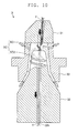
- the spinning section 3 is a so-called pneumatic spinning device adapted to twist the fiber bundle F by the whirling airflow.
- black arrows indicate the feeding direction of the fiber bundle F and the spun yarn Y, and white arrows indicate a flowing direction of the supplied air.
- the spinning section 3 generates the whirling airflow in a spinning chamber SC by an airflow injected from a nozzle block 33, and twists the fiber bundle F with such a whirling airflow.
- the spinning chamber SC is divided into a space SC1 formed between a fiber guide 31 and a spindle 32, and a space SC2 formed between the spindle 32 and the nozzle block 33.
- a trailing end of the fibers constituting the fiber bundle F is reversed by the whirling airflow (see chain double dashed lines in FIG. 10 ).
- the trailing end of the reversed fibers is whirled by the whirling airflow (see chain double dashed lines in FIG. 10 ).
- the fibers whirled by the whirling airflow are sequentially wound around fibers at a center portion. In this manner, the spinning section 3 can twist the fiber bundle F and spin the fiber bundle F into the spun yarn Y.
- the fiber guide 31 is provided with a needle 31n.
- the needle 31n guides the fiber bundle F to a fiber passage 32h, and prevents the twists of the fiber bundle F from being transmitted upstream.
- the needle 31n may be omitted.
- the spinning section 3 adapted to twist the fiber bundle F with the whirling airflow is arranged in the spinning unit 10, the production efficiency of the spun yarn Y in each spinning unit 10 can be improved, and the production efficiency of the package P in the spinning machine 100 can be improved.
- the spinning machine 100 according to one embodiment of the present invention has been described above, but the present invention is not limited to the above embodiment, and the structure described above can be changed to the following structure, for example.
- the braking section 21, the reverse-rotation roller 22, the driving section 23, the guiding section 24, and the yarn joining section 25 are arranged in the operation cart 20, but the braking section 21, the reverse-rotation roller 22, the driving section 23, the guiding section 24, and the yarn joining section 25 may be arranged in each spinning unit 10.
- a driving section of the drafting section 2 and a driving section of the winding section 6 may be independently arranged in each spinning unit 10, and an independent winding operation may be carried out in each spinning unit 10.
- a plurality of spinning units 10, the operation cart 20, and the doffing cart 30 are controlled by the control section 40, but a unit control section for individually controlling each spinning unit 10 may be arranged in each spinning unit 10. In this case, the control section 40 collectively controls the plurality of spinning units 10.
- the spun yarn Y is cut by the cutter 41, but the supply of air to the spinning section 3 may be stopped and the spun yarn Y may be cut by interrupting the production of the spun yarn Y by the spinning section 3.
- the reverse-rotation roller 22 is moved by the pneumatic actuator 23d, but the reverse-rotation roller 22 may be moved by an electric motor or a cam mechanism.
- the pneumatic actuator 23d is a double-acting pneumatic actuator, but the reverse-rotation roller 22 may be moved by a single-acting pneumatic actuator and an urging member such as a spring.
- the single-acting pneumatic actuator may be used to move the reverse-rotation roller 22 to the contacting position, and the urging member such as the spring may be used to move the reverse-rotation roller 22 to the receded position. Since the urging force of the urging member such as the spring changes by displacement of the urging member, the difference in the contact pressure of the reverse-rotation roller 22 and the package P becomes large depending on the outer diameter of the package P. Therefore, the pneumatic actuator 23d is preferably a double-acting pneumatic actuator.
- the spinning machine 100 is illustrated to include one operation cart 20 and one doffing cart 30. According to the number of the spinning units 10 arranged in the spinning machine 100, a plurality of operation carts 20 and/or a plurality of doffing carts 30 may be arranged in the spinning machine 100.
- the term immediately before is intended to mean a time period that is sufficiently short to prevent the yarn from slackening. If the package and the driving roller are made to contact one another while the reverse-rotation roller is still making contact with the package, the reverse-rotation roller becomes an obstacle. If the reverse-rotation roller is separated from the package long before the package is brought into contact with the driving roller, the yarn may slacken. Therefore, the period of time in which the package is free (that is, when the package is not making contact with the reverse-rotation roller and the driving roller) is preferably minimized as much as possible. Specifically, such a period of time is very close to 0 seconds but should be different from 0 seconds. In embodiments of the invention, the reverse-rotation roller and the package are separated less than 1 second, less than 0,5 seconds or less than 0,1 seconds before the package reaches the contacting position.
Abstract
Description
- The present invention relates to a spinning machine.
- Conventionally, there is known a spinning unit adapted to draft a fiber bundle and twist the drafted fiber bundle to produce a spun yarn (see e.g., Japanese Unexamined Patent Publication No.
2011-99192 - Conventionally, there is known a spinning machine including a plurality of spinning units (see e.g., Japanese Unexamined Patent Publication No.
2011-84854 - The spinning unit swings the cradle when the continuation of the spun yarn is disconnected, and separates the package from the driving roller. After stopping the rotation of the package by the braking section, the operation cart makes the reverse-rotation roller to contact with the package and rotates the package in the unwinding direction (hereinafter, simply referred to as "reverse rotation"). The operation cart catches the spun yarn and guides the spun yarn to a predetermined position by the guiding section, and joins the yarn ends of the spun yarn by the yarn joining section. Thereafter, the spinning unit swings the cradle again, and makes the package to contact with the driving roller. The spinning unit can resume formation of the package through such series of processes.
- The inventor recognized that, in the prior art, while separating the reverse-rotation roller from the package, the package may reversely rotate unintendedly accompanying movement of the reverse-rotation roller. When the reverse-rotation roller is separated from the package immediately after the spun yarn is joined by the yarn joining section, the package may reversely rotate unintendedly and the spun yarn may slacken.
- An object of the present invention is to provide a spinning machine in which a spun yarn does not slacken in a series of processes after formation of a package is interrupted and until the formation of the package is resumed.
- According to an aspect of the present invention, a spinning machine includes a plurality of spinning units, each spinning unit being adapted to wind a spun yarn to form a package. The spinning machine includes a driving roller adapted to make contact with the package to rotate the package in a winding direction, a cradle adapted to move the package to a contacting position and a receded position with respect to the driving roller, a reverse-rotation roller adapted to make contact with the package to rotate the package in an unwinding direction that is in an opposite direction of the winding direction, a driving section adapted to make the package and the reverse-rotation roller to contact with or separated from one another, and a control section adapted to control the driving section to separate the reverse-rotation roller and the package immediately before the package reaches the contacting position with respect to the driving roller by the package being moved by the cradle.
- Since the package makes contact with the driving roller immediately after the reverse-rotation roller is separated from the package, the package does not reversely rotate unintendedly. Accordingly, the spun yarn can be prevented from slackening.
- The control section is adapted to control the driving section such that a contact pressure of the reverse-rotation roller and the package is substantially constant regardless of an outer diameter of the package. Even if the outer diameter of the package differs, a difference in the contact pressure of the reverse-rotation roller and the package can be reduced. Accordingly, deformation of the package and degradation in quality of the spun yarn wound into the package thus can be prevented.
- The driving section is a pneumatic actuator. A timing in which the reverse-rotation roller separates from the package can be controlled at high accuracy. Therefore, since the package makes contact with the driving roller immediately after the reverse-rotation roller is separated from the package, the package does not reversely rotate unintendedly. Accordingly, the spun yarn can be prevented from slackening. Even if the outer diameter of the package differs, the difference in the contact pressure of the reverse-rotation roller and the package can be reduced. Accordingly, the deformation of the package and the degradation in the quality of the spun yarn wound into the package can be prevented.
- The spinning machine further includes an operation cart adapted to travel to one of the spinning units when a continuation of the spun yarn is disconnected in such spinning unit and to perform a yarn joining operation. The operation cart includes the reverse-rotation roller, the driving section, a braking section adapted to brake rotation of the package, a guiding section adapted to catch and guide the disconnected spun yarn, and a yarn joining section adapted to join yarn ends of the disconnected spun yarn. A structure of each spinning unit thus can be simplified, and a structure of the spinning machine can be simplified.
- Each of the spinning units includes a spinning section adapted to twist a fiber bundle by a whirling airflow. Accordingly, production efficiency of the spun yarn in each spinning unit thus can be improved, and production efficiency of the package in the spinning machine can be improved.
-
-
FIG. 1 is a view illustrating an overall structure of a spinning machine; -
FIG. 2 is a view illustrating a structure of a spinning unit and an operation cart; -
FIG. 3 is a view illustrating a process of stopping rotation of a package; -
FIG. 4 is a view illustrating a process of reversely rotating the package; -
FIG. 5 is a view illustrating a process of catching a disconnected spun yarn; -
FIG. 6 is a view illustrating a process of guiding the disconnected spun yarn; -
FIG. 7 is a view illustrating a process of resuming formation of the package; -
FIG. 8 is a view illustrating a structure of a driving section; -
FIG. 9A is a view illustrating a state in which a reverse-rotation roller is making contact with the package; -
FIG. 9B is a view illustrating a state in which the reverse-rotation roller is separated from the package; and -
FIG. 10 is a view illustrating a structure of a spinning section. - First, with reference to
FIG. 1 , an overall structure of aspinning machine 100 will be briefly described. InFIG. 1 , black arrows indicate a travelling direction of anoperation cart 20, and white arrows indicate a travelling direction of adoffing cart 30. - The
spinning machine 100 includes a plurality ofspinning units 10. Thespinning machine 100 includes theoperation cart 20, thedoffing cart 30, and acontrol section 40. - The
spinning unit 10 is adapted to draft a fiber bundle F and twist the drafted fiber bundle F to produce a spun yarn Y. Thespinning unit 10 can form a package P by winding the spun yarn Y. A detailed structure of thespinning unit 10 will be described later. - The
operation cart 20 can travel along a rail R1 extending in a direction in which thespinning units 10 are arranged. When a continuation of the spun yarn Y is disconnected in one of thespinning units 10, theoperation cart 20 travels to therelevant spinning unit 10 and performs a yarn joining operation. A detailed structure of theoperation cart 20 will be described later. - The
doffing cart 30 can travel along a rail R2 extending in a direction in which thespinning units 10 are arranged. When the package P is fully wound in one of thespinning units 10, thedoffing cart 30 can travel to therelevant spinning unit 10 and collect the package P. The doffingcart 30 can set a new bobbin B to thespinning unit 10. The doffingcart 30 may perform only an operation of collecting the fully-wound package P. If the collecting of the package P and the setting of the new bobbin B are manually performed by an operator, the doffingcart 30 may be omitted. - The
control section 40 can control each spinningunit 10, theoperation cart 20, and the like. For example, when the continuation of the spun yarn Y is disconnected in one of the spinningunits 10, thecontrol section 40 controls therelevant spinning unit 10 to interrupt the formation of the package P. After controlling theoperation cart 20 to perform the yarn joining operation, thecontrol section 40 controls thespinning unit 10 to resume the formation of the package P. - Next, with reference to
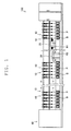
FIG. 2 , the structure of thespinning unit 10 and theoperation cart 20 will be described. InFIG. 2 , black arrows indicate a feeding direction of the fiber bundle F and the spun yarn Y, and a white arrow indicates a rotating direction of the package P. - First, the spinning
unit 10 will be described. The spinningunit 10 includes asliver supplying section 1, adrafting section 2, aspinning section 3, adefect detecting section 4, atension stabilizing section 5, and a windingsection 6 along the feeding direction of the fiber bundle F and the spun yarn Y. - The
sliver supplying section 1 is adapted to supply the fiber bundle F to thedrafting section 2. Thesliver supplying section 1 includes asliver case 11 and a sliver guide (not illustrated). The fiber bundle F accumulated in thesliver case 11 is guided by the sliver guide to thedrafting section 2. - The
drafting section 2 drafts the fiber bundle F to make a thickness of the fiber bundle F uniform. Thedrafting section 2 includes four sets ofdraft roller pairs back roller pair 2a, thethird roller pair 2b, themiddle roller pair 2c, and thefront roller pair 2d, along the feeding direction of the fiber bundle F. Each of thedraft roller pairs middle roller pair 2c. Since the bottom rollers and the top rollers rotate while sandwiching the fiber bundle F, thedraft roller pairs drafting section 2 can draft the fiber bundle F by a difference in a feeding speed of thedraft roller pairs - The
spinning section 3 twists the drafted fiber bundle F to produce the spun yarn Y. Thespinning section 3 is arranged downstream of thedrafting section 2 in the travelling direction of the spun yarn Y. Thespinning section 3 can produce the spun yarn Y from the appropriately drafted fiber bundle F. A structure of thespinning section 3 will be described later. - The
defect detecting section 4 detects a defective part of the produced spun yarn Y. Specifically, thedefect detecting section 4 irradiates the spun yarn Y with a light emitting diode (not illustrated) as a light source, and detects a reflected light quantity from the spun yarn Y. Thedefect detecting section 4 is connected to acontrol section 40 via an analyzer (not illustrated). Thecontrol section 40 can determine presence or absence of the defective part in accordance with a detection signal from thedefect detecting section 4. Acutter 41 capable of cutting the spun yarn Y is provided in proximity to thedefect detecting section 4. In addition to abnormality in which a portion of the spun yarn Y is too thick (thick yarn) or too thin (thin yarn), the defective part of the spun yarn Y includes foreign substances contained in the spun yarn Y. Instead of an optical sensor according to the present embodiment, a capacitance sensor or the like can be adopted as thedefect detecting section 4. - The
tension stabilizing section 5 is adapted to appropriately maintain and stabilize a tension applied to the spun yarn Y. Thetension stabilizing section 5 includes an unwindingmember 51 and aroller 52. The unwindingmember 51 rotates with theroller 52 when the tension applied to the spun yarn Y is low, and winds the spun yarn Y around theroller 52. The unwindingmember 51 rotates independently from theroller 52 when the tension applied to the spun yarn Y is high, and unwinds the spun yarn Y wound around theroller 52. Thetension stabilizing section 5 can appropriately maintain and stabilize the tension applied to the spun yarn Y. Theroller 52 is rotatably driven by a motor (not illustrated). - The winding
section 6 is adapted to form the package P by winding the spun yarn Y. The windingsection 6 includes a drivingroller 61 and acradle 62. The drivingroller 61 is rotatably driven by a motor (not illustrated), and rotates a bobbin B rotatably held by thecradle 62. Accordingly, the windingsection 6 can wind the spun yarn Y to form the package P, while traversing the spun yarn Y by a traverse device (not illustrated). - Next, the
operation cart 20 will be described. Theoperation cart 20 includes abraking section 21, a reverse-rotation roller 22, a drivingsection 23, a guidingsection 24, and ayarn joining section 25. - The
braking section 21 is adapted to make contact with the package P and brake the rotation of the package P (seeFIG. 3 ). In the present embodiment, thebraking section 21 includes aplate 21a adapted to make contact with an outer peripheral surface of the package P, and anarm 21b adapted to support theplate 21a. Thebraking section 21 merely needs to be able to make contact with the package P and brake the rotation of the package P, and a shape, a structure, and the like of thebraking section 21 are not limited. - The reverse-
rotation roller 22 makes contact with the package P to rotate (reversely rotate) the package P in an unwinding direction (a direction opposite to the winding direction) (seeFIG. 4 ,FIG. 5 , andFIG. 6 ). Specifically, after theplate 21a of thebraking section 21 separates from the outer peripheral surface of the package P, the reverse-rotation roller 22 makes contact with the package P and reversely rotates the package P. - The driving
section 23 rotates the reverse-rotation roller 22 (seeFIG. 5 andFIG. 6 ). In the present embodiment, the drivingsection 23 uses anelectric motor 23a, to be described later, to rotate the reverse-rotation roller 22. The drivingsection 23 can move the reverse-rotation roller 22 to make contact with or separate from the package P (seeFIG. 4 andFIG. 7 ). In the present embodiment, the drivingsection 23 uses apneumatic actuator 23d, to be described later, to move the reverse-rotation roller 22. The drivingsection 23 is driven in accordance with a control signal from thecontrol section 40. Thecontrol section 40 can control the drivingsection 23. - The guiding
section 24 is adapted to catch the disconnected spun yarn Y and guide the spun yarn Y to a predetermined position (seeFIG. 5 andFIG. 6 ). The guidingsection 24 includes afirst guiding portion 24a adapted to catch the spun yarn Y from the package P and guide the spun yarn Y to a predetermined position, and asecond guiding portion 24b adapted to catch the spun yarn Y spun from thespinning section 3 and guide the spun yarn Y to a predetermined position. Operations of thefirst guiding portion 24a and thesecond guiding portion 24b will be described later. - The
yarn joining section 25 joins yarn ends of the disconnected spun yarn Y (seeFIG. 6 ). Specifically, theyarn joining section 25 joins the yarn end of the spun yarn Y guided by thefirst guiding portion 24a and the yarn end of the spun yarn Y guided by thesecond guiding portion 24b. The "disconnected spun yarn Y" is a concept including at least the spun yarn Y cut by thecutter 41 and the spun yarn Y disconnected when abnormal tension is applied on the spun yarn Y. In addition to an air splicer device adapted to join the yarn ends of the spun yarn Y by a whirling airflow, a mechanical splicer device and the like may be adopted for theyarn joining section 25. - As described above, since the
operation cart 20 includes thebraking section 21, the reverse-rotation roller 22, the drivingsection 23, the guidingsection 24, and theyarn joining section 25, the structure of each spinningunit 10 can be simplified and the structure of the spinningmachine 100 can be simplified. - Next, with reference to
FIG. 3 to FIG. 7 , a series of processes after thespinning unit 10 interrupts the formation of the package P and until the formation of the package P is resumed will be described. InFIG. 3 to FIG. 7 , black arrows indicate a moving direction of each member constituting thespinning unit 10 and theoperation cart 20, and a white arrow indicates the rotating direction of the package P. - When the
defect detecting section 4 detects a defective part of the spun yarn Y, the spinningunit 10 uses thecutter 41 to cut the spun yarn Y. One end of the disconnected spun yarn Y (the spun yarn Y located downstream of the cutter 41) is thus wound into the package P. The other end of the disconnected spun yarn Y (the spun yarn Y located upstream of the cutter 41) is sucked and held at a suction port (not illustrated) arranged in proximity to thecutter 41. - Next, the spinning
unit 10 swings thecradle 62 to separate the package P from the driving roller 61 (see the black arrows inFIG. 3 ). The package P thus continues to rotate by an inertia force (see the white arrow inFIG. 3 ). Theoperation cart 20 travels to therelevant spinning unit 10 immediately after thecutter 41 cuts the spun yarn Y. - Next, the
operation cart 20 uses thebraking section 21 to stop the rotation of the package P. Specifically, theoperation cart 20 swings thearm 21b to make theplate 21a contact with the outer peripheral surface of the package P (see the black arrows inFIG. 3 ). Theoperation cart 20 thus stops the rotation of the package P by friction between the package P and theplate 21a. - Next, the
operation cart 20 uses the reverse-rotation roller 22 to reversely rotate the package P. Theoperation cart 20 reversely rotates the package P such that thefirst guiding portion 24a can catch the spun yarn Y wound around the package P. First, theoperation cart 20 swings thearm 21b to separate theplate 21a from the outer peripheral surface of the package P (see the black arrows inFIG. 4 ). Thereafter, theoperation cart 20 makes the reverse-rotation roller 22 to contact with the package P to reversely rotate the package P. Specifically, theoperation cart 20 moves the reverse-rotation roller 22 from a receded position, which is a position located away from the package P, to a contacting position, which is a position of making contact with the package P (see the black arrows inFIG. 4 ). Theoperation cart 20 then rotates the reverse-rotation roller 22 to reversely rotate the package P (see the white arrow inFIG. 4 ). The detailed description of the drivingsection 23 will be made later. - The
control section 40 controls the drivingsection 23 such that a contact pressure of the reverse-rotation roller 22 and the package P becomes substantially constant independent from the outer diameter of the package P. Even if the outer diameter of the package P differs, the difference in the contact pressure of the reverse-rotation roller 22 and the package P can be reduced. Thus, deformation of the package P and degradation in quality of the spun yarn Y wound into the package P can be prevented. - Next, the
operation cart 20 uses the guidingsection 24 to catch the disconnected spun yarn Y and guide the spun yarn Y to a predetermined position. Specifically, thefirst guiding portion 24a is swung downward from a standby position (downstream in the yarn travelling direction) to catch the spun yarn Y wound around the package P (see the black arrow inFIG. 5 ). Thefirst guiding portion 24a is swung upward while sucking and holding the spun yarn Y to guide the spun yarn Y to a predetermined position (see the black arrow inFIG. 6 ). Thesecond guiding portion 24b is swung upward from a standby position (upstream in the yarn travelling direction) to catch the spun yarn Y spun from the spinning section 3 (see the black arrow inFIG. 5 ). Thesecond guiding portion 24b is swung downward while sucking and holding the spun yarn Y to guide the spun yarn Y to a predetermined position (see the black arrow inFIG. 6 ). - Next, the
operation cart 20 joins the yarn end of the spun yarn Y guided to the predetermined position by thefirst guiding portion 24a and the yarn end of the spun yarn Y guided to the predetermined position by thesecond guiding portion 24b. - Thereafter, the spinning
unit 10 resumes the formation of the package P. The spinningunit 10 swings thecradle 62 to move the package P in a direction in which the package P is moved closer to the driving roller 61 (see the black arrow inFIG. 7 ) . In this case, theoperation cart 20 separates the reverse-rotation roller 22 from the package P by moving the reverse-rotation roller 22 from the contacting position to the receded position (see the black arrow inFIG. 7 ). Thus, the reverse-rotation roller 22 is separated from the package P immediately before the package P makes contact with the drivingroller 61. That is, immediately before the package P is moved by thecradle 62 and the package P makes contact with the drivingroller 61, thecontrol section 40 controls the drivingsection 23 to separate the reverse-rotation roller 22 from the package P. - In the spinning
machine 100, since the package P makes contact with the drivingroller 61 immediately after the reverse-rotation roller 22 separates from the package P, the package P does not reversely rotate unintendedly. The spun yarn Y thus can be prevented from slackening. - Next, with reference to
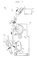
FIG. 8 ,FIG. 9A, and FIG. 9B , a structure and an operation of the drivingsection 23 will be described. InFIG. 8 ,FIG. 9A, and FIG. 9B , black arrows indicate a movement direction of each member of the drivingsection 23. - The driving
section 23 includes anelectric motor 23a, anarm 23b, a sub-arm 23c, apneumatic actuator 23d, and alever 23e. - The
electric motor 23a is mounted to one end of thearm 23b. In the present embodiment, theelectric motor 23a is a servo motor. Theelectric motor 23a may be a stepping motor or the like, and is not limited to any type. - The
arm 23b is mounted in a freely swinging manner with a swing shaft SH1 as a center. A first pulley 23ba and a second pulley 23bb are arranged inside thearm 23b. The first pulley 23ba is rotated by theelectric motor 23a. The second pulley 23bb is rotated by a belt 23bc wound around the second pulley 23bb and the first pulley 23ba. - The sub-arm 23c is mounted in a freely swinging manner with a swing shaft SH2 as a center. A third pulley 23ca and a fourth pulley 23cb are provided inside the sub-arm 23c. The third pulley 23ca is mounted to the second pulley 23bb provided inside the
arm 23b. The fourth pulley 23cb is rotated by a belt 23cc wound around the fourth pulley 23cb and the third pulley 23ca. The reverse-rotation roller 22 is mounted on the rotation shaft of the fourth pulley 23cb. - The
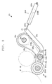
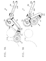
pneumatic actuator 23d includes a cylinder 23da, a piston 23db, and a rod 23dc. When air fed from an air supply source (not illustrated) is supplied to the cylinder 23da, the piston 23db is slidably moved in a direction in which the piston 23db moves closer to the package P (seeFIG. 9B ). The rod 23dc mounted to the piston 23db is thus slidably moved with the piston 23db, and thelever 23e is swung in a direction in which thelever 23e moves away from the package P (seeFIG. 9B ). As a result, the reverse-rotation roller 22 is moved to a receded position, which is a position located away from the package P (seeFIG. 9B ). When the air in the cylinder 23da is sucked by a negative pressure pipe (not illustrated), the piston 23db is slidably moved in a direction in which the piston 23db moves away from the package P (seeFIG. 9A ). The rod 23dc mounted to the piston 23db is thus slidably moved with the piston 23db, and thelever 23e is swung in a direction in which thelever 23e moves closer to the package P (seeFIG. 9A ). As a result, the reverse-rotation roller 22 is moved to a contacting position, which is a position where the reverse-rotation roller 22 makes contact with the package P (seeFIG. 9A ). That is, thepneumatic actuator 23d is a double-acting pneumatic actuator. - The
lever 23e is mounted in a freely swinging manner with a pin P1 of the rod 23dc of thepneumatic actuator 23d as a center. Thelever 23e is mounted in a freely swinging manner with a pin P2 arranged on the sub-arm 23c as a center. One end (a first end) of thelever 23e is mounted to the rod 23dc, and the other end (a second end) of thelever 23e is mounted to the sub-arm 23c. - The operation of the driving
section 23 will be hereinafter described. First, with reference toFIG. 9A , a description will be made on the operation of when making the reverse-rotation roller 22 to contact with the package P. - The
control section 40 transmits a control signal to an electromagnetic valve or the like (not illustrated) and causes the air in the cylinder 23da to be sucked. The piston 23db is thus slidably moved, and the rod 23dc mounted to the piston 23db is moved in a direction in which the piston 23db retreats into the cylinder 23da. Therefore, thepneumatic actuator 23d swings thelever 23e mounted to the rod 23dc. - The
lever 23e swings the sub-arm 23c with the swing shaft SH2 as a center, and swings thearm 23b with the swing shaft SH1 as a center. Specifically, since the sub-arm 23c is mounted in a freely swinging manner with the swing shaft SH2 as a center, the sub-arm 23c is swung accompanying the swinging of thelever 23e. Since thearm 23b and the sub-arm 23b are respectively mounted in a freely swinging manner with the swing shaft SH1 as a center, thearm 23b is swung accompanying the swinging of thelever 23e. The drivingsection 23 thus can move the reverse-rotation roller 22 such that the reverse-rotation roller 22 makes contact with the package P. - Thereafter, the
control section 40 transmits a control signal to a relay or the like (not illustrated) to pass an electric current to theelectric motor 23a. The reverse-rotation roller 22 thus starts to rotate, and the package P making contact with the reverse-rotation roller 22 also starts to rotate. - Next, with reference to
FIG. 9B , a description will be made of the operation of when separating the reverse-rotation roller 22 from the package P. - The
control section 40 transmits a control signal to the relay or the like (not illustrated) to shield the power supply of theelectric motor 23a. The reverse-rotation roller 22 thus stops rotating, and the package P that has been rotating while making contact with the reverse-rotation roller 22 also stops rotating. - Thereafter, the
control section 40 transmits a control signal to the electromagnetic valve or the like (not illustrated) to supply the air to the cylinder 23da. The piston 23db is thus slidably moved, and the rod 23dc mounted to the piston 23db is moved in a direction in which the piston 23db advances from the cylinder 23da. Thepneumatic actuator 23d swings thelever 23e mounted to the rod 23dc. - The
lever 23e swings the sub-arm 23c with the swing shaft SH2 as a center, and swings thearm 23b with the swing shaft SH1 as a center. Specifically, since the sub-arm 23c is mounted in a freely swinging manner with the swing shaft SH2 as a center, the sub-arm 23c is swung accompanying the swinging of thelever 23e. Since thearm 23b and the sub-arm 23c are respectively mounted in a freely swinging manner with the swing shaft SH1 as a center, thearm 23b is swung accompanying the swinging of thelever 23e. The drivingsection 23 thus can move the reverse-rotation roller 22 such that the reverse-rotation roller 22 is separated from the package P. - As described above, the driving
section 23 of the present embodiment uses thepneumatic actuator 23d to move the reverse-rotation roller 22. The spinningmachine 100 thus can control the timing in which the reverse-rotation roller 22 is separated from the package P at high accuracy. Therefore, since the package P can be made into contact with the drivingroller 61 immediately after separating the reverse-rotation roller 22 from the package P, the package P does not reversely rotate unintendedly. The spun yarn Y thus can be prevented from slackening. - Even if the outer diameter of the package P differs, the difference in the contact pressure of the reverse-
rotation roller 22 and the package P can be reduced. The deformation of the package P and the degradation in the quality of the spun yarn Y wound into the package P thus can be prevented. - Next, with reference to
FIG. 10 , a structure of thespinning section 3 will be described. Thespinning section 3 is a so-called pneumatic spinning device adapted to twist the fiber bundle F by the whirling airflow. InFIG. 10 , black arrows indicate the feeding direction of the fiber bundle F and the spun yarn Y, and white arrows indicate a flowing direction of the supplied air. - The
spinning section 3 generates the whirling airflow in a spinning chamber SC by an airflow injected from anozzle block 33, and twists the fiber bundle F with such a whirling airflow. The spinning chamber SC is divided into a space SC1 formed between afiber guide 31 and aspindle 32, and a space SC2 formed between thespindle 32 and thenozzle block 33. - In the space SC1, a trailing end of the fibers constituting the fiber bundle F is reversed by the whirling airflow (see chain double dashed lines in
FIG. 10 ). In the space SC2, the trailing end of the reversed fibers is whirled by the whirling airflow (see chain double dashed lines inFIG. 10 ). The fibers whirled by the whirling airflow are sequentially wound around fibers at a center portion. In this manner, thespinning section 3 can twist the fiber bundle F and spin the fiber bundle F into the spun yarn Y. - In the
spinning section 3, thefiber guide 31 is provided with aneedle 31n. Theneedle 31n guides the fiber bundle F to afiber passage 32h, and prevents the twists of the fiber bundle F from being transmitted upstream. However, theneedle 31n may be omitted. - As described above, since the
spinning section 3 adapted to twist the fiber bundle F with the whirling airflow is arranged in thespinning unit 10, the production efficiency of the spun yarn Y in each spinningunit 10 can be improved, and the production efficiency of the package P in the spinningmachine 100 can be improved. - The spinning
machine 100 according to one embodiment of the present invention has been described above, but the present invention is not limited to the above embodiment, and the structure described above can be changed to the following structure, for example. - In the embodiment described above, the
braking section 21, the reverse-rotation roller 22, the drivingsection 23, the guidingsection 24, and theyarn joining section 25 are arranged in theoperation cart 20, but thebraking section 21, the reverse-rotation roller 22, the drivingsection 23, the guidingsection 24, and theyarn joining section 25 may be arranged in each spinningunit 10. A driving section of thedrafting section 2 and a driving section of the windingsection 6 may be independently arranged in each spinningunit 10, and an independent winding operation may be carried out in each spinningunit 10. - In the embodiment described above, a plurality of spinning
units 10, theoperation cart 20, and the doffingcart 30 are controlled by thecontrol section 40, but a unit control section for individually controlling each spinningunit 10 may be arranged in each spinningunit 10. In this case, thecontrol section 40 collectively controls the plurality of spinningunits 10. - In the embodiment described above, the spun yarn Y is cut by the
cutter 41, but the supply of air to thespinning section 3 may be stopped and the spun yarn Y may be cut by interrupting the production of the spun yarn Y by thespinning section 3. - In the embodiment described above, the reverse-
rotation roller 22 is moved by thepneumatic actuator 23d, but the reverse-rotation roller 22 may be moved by an electric motor or a cam mechanism. - In the embodiment described above, the
pneumatic actuator 23d is a double-acting pneumatic actuator, but the reverse-rotation roller 22 may be moved by a single-acting pneumatic actuator and an urging member such as a spring. For example, the single-acting pneumatic actuator may be used to move the reverse-rotation roller 22 to the contacting position, and the urging member such as the spring may be used to move the reverse-rotation roller 22 to the receded position. Since the urging force of the urging member such as the spring changes by displacement of the urging member, the difference in the contact pressure of the reverse-rotation roller 22 and the package P becomes large depending on the outer diameter of the package P. Therefore, thepneumatic actuator 23d is preferably a double-acting pneumatic actuator. - In
FIG. 1 , the spinningmachine 100 is illustrated to include oneoperation cart 20 and one doffingcart 30. According to the number of the spinningunits 10 arranged in the spinningmachine 100, a plurality ofoperation carts 20 and/or a plurality of doffingcarts 30 may be arranged in the spinningmachine 100. - The term immediately before is intended to mean a time period that is sufficiently short to prevent the yarn from slackening. If the package and the driving roller are made to contact one another while the reverse-rotation roller is still making contact with the package, the reverse-rotation roller becomes an obstacle. If the reverse-rotation roller is separated from the package long before the package is brought into contact with the driving roller, the yarn may slacken. Therefore, the period of time in which the package is free (that is, when the package is not making contact with the reverse-rotation roller and the driving roller) is preferably minimized as much as possible. Specifically, such a period of time is very close to 0 seconds but should be different from 0 seconds. In embodiments of the invention, the reverse-rotation roller and the package are separated less than 1 second, less than 0,5 seconds or less than 0,1 seconds before the package reaches the contacting position.
Claims (5)
- A spinning machine comprising:a plurality of spinning units (10), each spinning unit (10) being adapted to wind a spun yarn (Y) to form a package (P),a driving roller (61) adapted to make contact with the package (P) to rotate the package (P) in a winding direction,a cradle (62) adapted to move the package (P) to a contacting position and a receded position with respect to the driving roller (61),a reverse-rotation roller (22) adapted to make contact with the package (P) to rotate the package (P) in an unwinding direction that is in an opposite direction of the winding direction,a driving section (23) adapted to make the package (P) and the reverse-rotation roller (22) to contact with or separated from one another, anda control section (40) adapted to control the driving section (23) to separate the reverse-rotation roller (22) and the package (P) immediately before the package reaches the contacting position with respect to the driving roller (61) by the package (P) being moved by the cradle (62).
- The spinning machine according to claim 1, wherein the control section (40) is adapted to control the driving section (23) such that a contact pressure of the reverse-rotation roller (22) and the package (P) is substantially constant regardless of an outer diameter of the package (P).
- The spinning machine according to claim 1 or claim 2, wherein the driving section (23) includes a pneumatic actuator (23d).
- The spinning machine according to any one of claim 1 through claim 3, further comprising an operation cart (20) adapted to travel to one of the spinning units (10) when a continuation of the spun yarn (Y) is disconnected in such spinning unit (10) and to perform a yarn joining operation,
wherein the operation cart (20) includes:the reverse-rotation roller (22),the driving section (23),a braking section (21) adapted to brake rotation of the package (P),a guiding section (24) adapted to catch and guide the disconnected spun yarn (Y), and
a yarn joining section (25) adapted to join yarn ends of the disconnected spun yarn (Y). - The spinning machine according to any one of claim 1 through claim 4, wherein each of the spinning units (10) includes a spinning section (3) adapted to twist a fiber bundle (F) by a whirling airflow.
Applications Claiming Priority (1)
| Application Number | Priority Date | Filing Date | Title |
|---|---|---|---|
| JP2011206628A JP2013067484A (en) | 2011-09-21 | 2011-09-21 | Spinning machine |
Publications (3)
| Publication Number | Publication Date |
|---|---|
| EP2573231A2 true EP2573231A2 (en) | 2013-03-27 |
| EP2573231A3 EP2573231A3 (en) | 2017-03-29 |
| EP2573231B1 EP2573231B1 (en) | 2019-06-26 |
Family
ID=46799133
Family Applications (1)
| Application Number | Title | Priority Date | Filing Date |
|---|---|---|---|
| EP12183045.9A Not-in-force EP2573231B1 (en) | 2011-09-21 | 2012-09-05 | Spinning machine |
Country Status (3)
| Country | Link |
|---|---|
| EP (1) | EP2573231B1 (en) |
| JP (1) | JP2013067484A (en) |
| CN (1) | CN103014936B (en) |
Families Citing this family (6)
| Publication number | Priority date | Publication date | Assignee | Title |
|---|---|---|---|---|
| ITPD20130115A1 (en) * | 2013-04-30 | 2014-10-31 | Savio Macchine Tessili Spa | WINDER |
| JP2015067441A (en) | 2013-09-30 | 2015-04-13 | 村田機械株式会社 | Work truck for textile machine |
| JP2015161032A (en) * | 2014-02-25 | 2015-09-07 | 村田機械株式会社 | Yarn storage device, yarn winding unit therewith and yarn winder therewith |
| JP2018052638A (en) * | 2016-09-26 | 2018-04-05 | 村田機械株式会社 | Textile machine |
| CN109335871A (en) * | 2018-11-22 | 2019-02-15 | 卓郎(江苏)纺织机械有限公司 | The textile machine and its Yarn spinning method of driving device are reversed with yarn reel |
| JP2021001038A (en) * | 2019-06-19 | 2021-01-07 | 村田機械株式会社 | Abrasive wear determination system and fiber machine system |
Citations (2)
| Publication number | Priority date | Publication date | Assignee | Title |
|---|---|---|---|---|
| JP2011084854A (en) | 2009-09-18 | 2011-04-28 | Murata Machinery Ltd | Spinning machine |
| JP2011099192A (en) | 2009-10-07 | 2011-05-19 | Murata Machinery Ltd | Spinning unit |
Family Cites Families (9)
| Publication number | Priority date | Publication date | Assignee | Title |
|---|---|---|---|---|
| GB1063778A (en) * | 1963-03-22 | 1967-03-30 | Reiners Walter | Winding machine |
| DE3827345A1 (en) * | 1988-08-12 | 1990-03-01 | Fritz Stahlecker | Servicing appliance movable along a spinning machine and having means for locating a thread of a bobbin |
| JP3951534B2 (en) * | 2000-01-13 | 2007-08-01 | 村田機械株式会社 | Package diameter measuring device |
| DE10102907A1 (en) * | 2001-01-23 | 2002-07-25 | Schlafhorst & Co W | Process for producing a staple fiber yarn |
| JP2002294523A (en) * | 2001-03-29 | 2002-10-09 | Murata Mach Ltd | Method for piecing and piecing device |
| JP3700706B2 (en) * | 2003-03-13 | 2005-09-28 | 村田機械株式会社 | Spinning machine |
| JP4120635B2 (en) * | 2004-11-19 | 2008-07-16 | 村田機械株式会社 | Textile machinery |
| JP2006306586A (en) * | 2005-04-28 | 2006-11-09 | Murata Mach Ltd | Elastic yarn package driving device in core yarn manufacturing apparatus |
| JP2010189083A (en) * | 2009-02-16 | 2010-09-02 | Murata Machinery Ltd | Fiber machine |
-
2011
- 2011-09-21 JP JP2011206628A patent/JP2013067484A/en not_active Withdrawn
-
2012
- 2012-08-20 CN CN201210296070.7A patent/CN103014936B/en active Active
- 2012-09-05 EP EP12183045.9A patent/EP2573231B1/en not_active Not-in-force
Patent Citations (2)
| Publication number | Priority date | Publication date | Assignee | Title |
|---|---|---|---|---|
| JP2011084854A (en) | 2009-09-18 | 2011-04-28 | Murata Machinery Ltd | Spinning machine |
| JP2011099192A (en) | 2009-10-07 | 2011-05-19 | Murata Machinery Ltd | Spinning unit |
Also Published As
| Publication number | Publication date |
|---|---|
| JP2013067484A (en) | 2013-04-18 |
| CN103014936B (en) | 2016-06-29 |
| CN103014936A (en) | 2013-04-03 |
| EP2573231A3 (en) | 2017-03-29 |
| EP2573231B1 (en) | 2019-06-26 |
Similar Documents
| Publication | Publication Date | Title |
|---|---|---|
| EP2573235B1 (en) | Spinning machine | |
| EP2573231B1 (en) | Spinning machine | |
| EP2573232A2 (en) | Apparatus for joining a yarn, and yarn winding machine and unit including same | |
| EP2573023B1 (en) | Yarn winding machine and yarn winding unit | |
| EP2573217B1 (en) | Spinning unit, spinning machine and yarn processing method | |
| CN101994176A (en) | Spinning machine | |
| EP2573030B1 (en) | Yarn winding machine | |
| CN103848287B (en) | Yarn winding machine and the fibre machinery for possessing Yarn winding machine | |
| EP3040458B1 (en) | Core yarn supplying device, spinning machine, and method of supplying core yarn | |
| EP2862826B1 (en) | Yarn winding machine | |
| CN110158207B (en) | Air spinning machine and air spinning method | |
| CN106048797B (en) | Textile machine | |
| EP2749517A1 (en) | Spinning machine | |
| EP2853510B1 (en) | Service vehicle of textile machine | |
| WO2013031606A1 (en) | Spinning machine | |
| CN108286093B (en) | Spinning machine | |
| EP3168340B1 (en) | Air spinning device and spinning machine | |
| EP2862825B1 (en) | Winding device and yarn winding machine including the same | |
| CN211171024U (en) | Spinning mechanism of yarn | |
| JP2013057152A (en) | Yarn winder | |
| EP2848566A1 (en) | Yarn winding machine | |
| JP2022085989A (en) | Spinning machine | |
| CN113774526A (en) | Rotor spinning machine | |
| CN110699796A (en) | Spinning mechanism of yarn | |
| JP2022130239A (en) | spinning machine |
Legal Events
| Date | Code | Title | Description |
|---|---|---|---|
| PUAI | Public reference made under article 153(3) epc to a published international application that has entered the european phase |
Free format text: ORIGINAL CODE: 0009012 |
|
| AK | Designated contracting states |
Kind code of ref document: A2 Designated state(s): AL AT BE BG CH CY CZ DE DK EE ES FI FR GB GR HR HU IE IS IT LI LT LU LV MC MK MT NL NO PL PT RO RS SE SI SK SM TR |
|
| AX | Request for extension of the european patent |
Extension state: BA ME |
|
| PUAL | Search report despatched |
Free format text: ORIGINAL CODE: 0009013 |
|
| AK | Designated contracting states |
Kind code of ref document: A3 Designated state(s): AL AT BE BG CH CY CZ DE DK EE ES FI FR GB GR HR HU IE IS IT LI LT LU LV MC MK MT NL NO PL PT RO RS SE SI SK SM TR |
|
| AX | Request for extension of the european patent |
Extension state: BA ME |
|
| RIC1 | Information provided on ipc code assigned before grant |
Ipc: B65H 67/08 20060101ALI20170218BHEP Ipc: D01H 5/88 20060101AFI20170218BHEP |
|
| STAA | Information on the status of an ep patent application or granted ep patent |
Free format text: STATUS: REQUEST FOR EXAMINATION WAS MADE |
|
| 17P | Request for examination filed |
Effective date: 20170918 |
|
| RBV | Designated contracting states (corrected) |
Designated state(s): AL AT BE BG CH CY CZ DE DK EE ES FI FR GB GR HR HU IE IS IT LI LT LU LV MC MK MT NL NO PL PT RO RS SE SI SK SM TR |
|
| GRAJ | Information related to disapproval of communication of intention to grant by the applicant or resumption of examination proceedings by the epo deleted |
Free format text: ORIGINAL CODE: EPIDOSDIGR1 |
|
| STAA | Information on the status of an ep patent application or granted ep patent |
Free format text: STATUS: GRANT OF PATENT IS INTENDED |
|
| GRAP | Despatch of communication of intention to grant a patent |
Free format text: ORIGINAL CODE: EPIDOSNIGR1 |
|
| INTG | Intention to grant announced |
Effective date: 20190111 |
|
| GRAS | Grant fee paid |
Free format text: ORIGINAL CODE: EPIDOSNIGR3 |
|
| GRAA | (expected) grant |
Free format text: ORIGINAL CODE: 0009210 |
|
| STAA | Information on the status of an ep patent application or granted ep patent |
Free format text: STATUS: THE PATENT HAS BEEN GRANTED |
|
| AK | Designated contracting states |
Kind code of ref document: B1 Designated state(s): AL AT BE BG CH CY CZ DE DK EE ES FI FR GB GR HR HU IE IS IT LI LT LU LV MC MK MT NL NO PL PT RO RS SE SI SK SM TR |
|
| REG | Reference to a national code |
Ref country code: GB Ref legal event code: FG4D |
|
| REG | Reference to a national code |
Ref country code: CH Ref legal event code: EP |
|
| REG | Reference to a national code |
Ref country code: DE Ref legal event code: R096 Ref document number: 602012061357 Country of ref document: DE |
|
| REG | Reference to a national code |
Ref country code: AT Ref legal event code: REF Ref document number: 1148385 Country of ref document: AT Kind code of ref document: T Effective date: 20190715 |
|
| REG | Reference to a national code |
Ref country code: IE Ref legal event code: FG4D |
|
| REG | Reference to a national code |
Ref country code: CH Ref legal event code: NV Representative=s name: BOVARD AG PATENT- UND MARKENANWAELTE, CH |
|
| REG | Reference to a national code |
Ref country code: NL Ref legal event code: MP Effective date: 20190626 |
|
| PG25 | Lapsed in a contracting state [announced via postgrant information from national office to epo] |
Ref country code: NO Free format text: LAPSE BECAUSE OF FAILURE TO SUBMIT A TRANSLATION OF THE DESCRIPTION OR TO PAY THE FEE WITHIN THE PRESCRIBED TIME-LIMIT Effective date: 20190926 Ref country code: FI Free format text: LAPSE BECAUSE OF FAILURE TO SUBMIT A TRANSLATION OF THE DESCRIPTION OR TO PAY THE FEE WITHIN THE PRESCRIBED TIME-LIMIT Effective date: 20190626 Ref country code: LT Free format text: LAPSE BECAUSE OF FAILURE TO SUBMIT A TRANSLATION OF THE DESCRIPTION OR TO PAY THE FEE WITHIN THE PRESCRIBED TIME-LIMIT Effective date: 20190626 Ref country code: HR Free format text: LAPSE BECAUSE OF FAILURE TO SUBMIT A TRANSLATION OF THE DESCRIPTION OR TO PAY THE FEE WITHIN THE PRESCRIBED TIME-LIMIT Effective date: 20190626 Ref country code: SE Free format text: LAPSE BECAUSE OF FAILURE TO SUBMIT A TRANSLATION OF THE DESCRIPTION OR TO PAY THE FEE WITHIN THE PRESCRIBED TIME-LIMIT Effective date: 20190626 Ref country code: AL Free format text: LAPSE BECAUSE OF FAILURE TO SUBMIT A TRANSLATION OF THE DESCRIPTION OR TO PAY THE FEE WITHIN THE PRESCRIBED TIME-LIMIT Effective date: 20190626 |
|
| PGFP | Annual fee paid to national office [announced via postgrant information from national office to epo] |
Ref country code: DE Payment date: 20190918 Year of fee payment: 8 Ref country code: CZ Payment date: 20190827 Year of fee payment: 8 |
|
| REG | Reference to a national code |
Ref country code: LT Ref legal event code: MG4D |
|
| PG25 | Lapsed in a contracting state [announced via postgrant information from national office to epo] |
Ref country code: BG Free format text: LAPSE BECAUSE OF FAILURE TO SUBMIT A TRANSLATION OF THE DESCRIPTION OR TO PAY THE FEE WITHIN THE PRESCRIBED TIME-LIMIT Effective date: 20190926 Ref country code: RS Free format text: LAPSE BECAUSE OF FAILURE TO SUBMIT A TRANSLATION OF THE DESCRIPTION OR TO PAY THE FEE WITHIN THE PRESCRIBED TIME-LIMIT Effective date: 20190626 Ref country code: LV Free format text: LAPSE BECAUSE OF FAILURE TO SUBMIT A TRANSLATION OF THE DESCRIPTION OR TO PAY THE FEE WITHIN THE PRESCRIBED TIME-LIMIT Effective date: 20190626 Ref country code: GR Free format text: LAPSE BECAUSE OF FAILURE TO SUBMIT A TRANSLATION OF THE DESCRIPTION OR TO PAY THE FEE WITHIN THE PRESCRIBED TIME-LIMIT Effective date: 20190927 |
|
| REG | Reference to a national code |
Ref country code: AT Ref legal event code: MK05 Ref document number: 1148385 Country of ref document: AT Kind code of ref document: T Effective date: 20190626 |
|
| PG25 | Lapsed in a contracting state [announced via postgrant information from national office to epo] |
Ref country code: SK Free format text: LAPSE BECAUSE OF FAILURE TO SUBMIT A TRANSLATION OF THE DESCRIPTION OR TO PAY THE FEE WITHIN THE PRESCRIBED TIME-LIMIT Effective date: 20190626 Ref country code: EE Free format text: LAPSE BECAUSE OF FAILURE TO SUBMIT A TRANSLATION OF THE DESCRIPTION OR TO PAY THE FEE WITHIN THE PRESCRIBED TIME-LIMIT Effective date: 20190626 Ref country code: PT Free format text: LAPSE BECAUSE OF FAILURE TO SUBMIT A TRANSLATION OF THE DESCRIPTION OR TO PAY THE FEE WITHIN THE PRESCRIBED TIME-LIMIT Effective date: 20191028 Ref country code: AT Free format text: LAPSE BECAUSE OF FAILURE TO SUBMIT A TRANSLATION OF THE DESCRIPTION OR TO PAY THE FEE WITHIN THE PRESCRIBED TIME-LIMIT Effective date: 20190626 Ref country code: NL Free format text: LAPSE BECAUSE OF FAILURE TO SUBMIT A TRANSLATION OF THE DESCRIPTION OR TO PAY THE FEE WITHIN THE PRESCRIBED TIME-LIMIT Effective date: 20190626 Ref country code: RO Free format text: LAPSE BECAUSE OF FAILURE TO SUBMIT A TRANSLATION OF THE DESCRIPTION OR TO PAY THE FEE WITHIN THE PRESCRIBED TIME-LIMIT Effective date: 20190626 |
|
| PGFP | Annual fee paid to national office [announced via postgrant information from national office to epo] |
Ref country code: CH Payment date: 20190919 Year of fee payment: 8 |
|
| PG25 | Lapsed in a contracting state [announced via postgrant information from national office to epo] |
Ref country code: IT Free format text: LAPSE BECAUSE OF FAILURE TO SUBMIT A TRANSLATION OF THE DESCRIPTION OR TO PAY THE FEE WITHIN THE PRESCRIBED TIME-LIMIT Effective date: 20190626 Ref country code: ES Free format text: LAPSE BECAUSE OF FAILURE TO SUBMIT A TRANSLATION OF THE DESCRIPTION OR TO PAY THE FEE WITHIN THE PRESCRIBED TIME-LIMIT Effective date: 20190626 Ref country code: IS Free format text: LAPSE BECAUSE OF FAILURE TO SUBMIT A TRANSLATION OF THE DESCRIPTION OR TO PAY THE FEE WITHIN THE PRESCRIBED TIME-LIMIT Effective date: 20191026 Ref country code: SM Free format text: LAPSE BECAUSE OF FAILURE TO SUBMIT A TRANSLATION OF THE DESCRIPTION OR TO PAY THE FEE WITHIN THE PRESCRIBED TIME-LIMIT Effective date: 20190626 |
|
| PG25 | Lapsed in a contracting state [announced via postgrant information from national office to epo] |
Ref country code: TR Free format text: LAPSE BECAUSE OF FAILURE TO SUBMIT A TRANSLATION OF THE DESCRIPTION OR TO PAY THE FEE WITHIN THE PRESCRIBED TIME-LIMIT Effective date: 20190626 |
|
| PG25 | Lapsed in a contracting state [announced via postgrant information from national office to epo] |
Ref country code: PL Free format text: LAPSE BECAUSE OF FAILURE TO SUBMIT A TRANSLATION OF THE DESCRIPTION OR TO PAY THE FEE WITHIN THE PRESCRIBED TIME-LIMIT Effective date: 20190626 Ref country code: DK Free format text: LAPSE BECAUSE OF FAILURE TO SUBMIT A TRANSLATION OF THE DESCRIPTION OR TO PAY THE FEE WITHIN THE PRESCRIBED TIME-LIMIT Effective date: 20190626 |
|
| PG25 | Lapsed in a contracting state [announced via postgrant information from national office to epo] |
Ref country code: IS Free format text: LAPSE BECAUSE OF FAILURE TO SUBMIT A TRANSLATION OF THE DESCRIPTION OR TO PAY THE FEE WITHIN THE PRESCRIBED TIME-LIMIT Effective date: 20200224 Ref country code: MC Free format text: LAPSE BECAUSE OF FAILURE TO SUBMIT A TRANSLATION OF THE DESCRIPTION OR TO PAY THE FEE WITHIN THE PRESCRIBED TIME-LIMIT Effective date: 20190626 |
|
| REG | Reference to a national code |
Ref country code: DE Ref legal event code: R097 Ref document number: 602012061357 Country of ref document: DE |
|
| PLBE | No opposition filed within time limit |
Free format text: ORIGINAL CODE: 0009261 |
|
| STAA | Information on the status of an ep patent application or granted ep patent |
Free format text: STATUS: NO OPPOSITION FILED WITHIN TIME LIMIT |
|
| PG2D | Information on lapse in contracting state deleted |
Ref country code: IS |
|
| PG25 | Lapsed in a contracting state [announced via postgrant information from national office to epo] |
Ref country code: LU Free format text: LAPSE BECAUSE OF NON-PAYMENT OF DUE FEES Effective date: 20190905 Ref country code: IE Free format text: LAPSE BECAUSE OF NON-PAYMENT OF DUE FEES Effective date: 20190905 |
|
| REG | Reference to a national code |
Ref country code: BE Ref legal event code: MM Effective date: 20190930 |
|
| 26N | No opposition filed |
Effective date: 20200603 |
|
| PG25 | Lapsed in a contracting state [announced via postgrant information from national office to epo] |
Ref country code: BE Free format text: LAPSE BECAUSE OF NON-PAYMENT OF DUE FEES Effective date: 20190930 Ref country code: SI Free format text: LAPSE BECAUSE OF FAILURE TO SUBMIT A TRANSLATION OF THE DESCRIPTION OR TO PAY THE FEE WITHIN THE PRESCRIBED TIME-LIMIT Effective date: 20190626 |
|
| GBPC | Gb: european patent ceased through non-payment of renewal fee |
Effective date: 20190926 |
|
| PG25 | Lapsed in a contracting state [announced via postgrant information from national office to epo] |
Ref country code: FR Free format text: LAPSE BECAUSE OF NON-PAYMENT OF DUE FEES Effective date: 20190930 Ref country code: GB Free format text: LAPSE BECAUSE OF NON-PAYMENT OF DUE FEES Effective date: 20190926 |
|
| REG | Reference to a national code |
Ref country code: DE Ref legal event code: R119 Ref document number: 602012061357 Country of ref document: DE |
|
| PG25 | Lapsed in a contracting state [announced via postgrant information from national office to epo] |
Ref country code: CZ Free format text: LAPSE BECAUSE OF NON-PAYMENT OF DUE FEES Effective date: 20200905 |
|
| REG | Reference to a national code |
Ref country code: CH Ref legal event code: PL |
|
| PG25 | Lapsed in a contracting state [announced via postgrant information from national office to epo] |
Ref country code: CY Free format text: LAPSE BECAUSE OF FAILURE TO SUBMIT A TRANSLATION OF THE DESCRIPTION OR TO PAY THE FEE WITHIN THE PRESCRIBED TIME-LIMIT Effective date: 20190626 |
|
| PG25 | Lapsed in a contracting state [announced via postgrant information from national office to epo] |
Ref country code: DE Free format text: LAPSE BECAUSE OF NON-PAYMENT OF DUE FEES Effective date: 20210401 Ref country code: MT Free format text: LAPSE BECAUSE OF FAILURE TO SUBMIT A TRANSLATION OF THE DESCRIPTION OR TO PAY THE FEE WITHIN THE PRESCRIBED TIME-LIMIT Effective date: 20190626 Ref country code: HU Free format text: LAPSE BECAUSE OF FAILURE TO SUBMIT A TRANSLATION OF THE DESCRIPTION OR TO PAY THE FEE WITHIN THE PRESCRIBED TIME-LIMIT; INVALID AB INITIO Effective date: 20120905 |
|
| PG25 | Lapsed in a contracting state [announced via postgrant information from national office to epo] |
Ref country code: CH Free format text: LAPSE BECAUSE OF NON-PAYMENT OF DUE FEES Effective date: 20200930 Ref country code: LI Free format text: LAPSE BECAUSE OF NON-PAYMENT OF DUE FEES Effective date: 20200930 |
|
| PG25 | Lapsed in a contracting state [announced via postgrant information from national office to epo] |
Ref country code: MK Free format text: LAPSE BECAUSE OF FAILURE TO SUBMIT A TRANSLATION OF THE DESCRIPTION OR TO PAY THE FEE WITHIN THE PRESCRIBED TIME-LIMIT Effective date: 20190626 |