EP2573022A2 - Yarn winding machine - Google Patents
Yarn winding machine Download PDFInfo
- Publication number
- EP2573022A2 EP2573022A2 EP12180661A EP12180661A EP2573022A2 EP 2573022 A2 EP2573022 A2 EP 2573022A2 EP 12180661 A EP12180661 A EP 12180661A EP 12180661 A EP12180661 A EP 12180661A EP 2573022 A2 EP2573022 A2 EP 2573022A2
- Authority
- EP
- European Patent Office
- Prior art keywords
- yarn
- bobbin
- winding
- cart
- main body
- Prior art date
- Legal status (The legal status is an assumption and is not a legal conclusion. Google has not performed a legal analysis and makes no representation as to the accuracy of the status listed.)
- Granted
Links
- 238000004804 winding Methods 0.000 title claims abstract description 198
- 238000005304 joining Methods 0.000 claims description 61
- 239000002699 waste material Substances 0.000 claims description 54
- 238000009987 spinning Methods 0.000 abstract description 121
- 239000000835 fiber Substances 0.000 description 25
- 238000012423 maintenance Methods 0.000 description 13
- 238000010042 air jet spinning Methods 0.000 description 7
- 238000011144 upstream manufacturing Methods 0.000 description 7
- 230000002093 peripheral effect Effects 0.000 description 5
- 230000007547 defect Effects 0.000 description 4
- 230000007423 decrease Effects 0.000 description 2
- 238000000034 method Methods 0.000 description 2
- 230000005856 abnormality Effects 0.000 description 1
- 238000007796 conventional method Methods 0.000 description 1
- 238000005520 cutting process Methods 0.000 description 1
- 238000001514 detection method Methods 0.000 description 1
- 238000004519 manufacturing process Methods 0.000 description 1
- 239000000463 material Substances 0.000 description 1
- 230000000644 propagated effect Effects 0.000 description 1
- 239000000126 substance Substances 0.000 description 1
Images


Classifications
-
- B—PERFORMING OPERATIONS; TRANSPORTING
- B65—CONVEYING; PACKING; STORING; HANDLING THIN OR FILAMENTARY MATERIAL
- B65H—HANDLING THIN OR FILAMENTARY MATERIAL, e.g. SHEETS, WEBS, CABLES
- B65H67/00—Replacing or removing cores, receptacles, or completed packages at paying-out, winding, or depositing stations
- B65H67/04—Arrangements for removing completed take-up packages and or replacing by cores, formers, or empty receptacles at winding or depositing stations; Transferring material between adjacent full and empty take-up elements
- B65H67/0405—Arrangements for removing completed take-up packages or for loading an empty core
- B65H67/0417—Arrangements for removing completed take-up packages or for loading an empty core for loading an empty core
-
- B—PERFORMING OPERATIONS; TRANSPORTING
- B65—CONVEYING; PACKING; STORING; HANDLING THIN OR FILAMENTARY MATERIAL
- B65H—HANDLING THIN OR FILAMENTARY MATERIAL, e.g. SHEETS, WEBS, CABLES
- B65H54/00—Winding, coiling, or depositing filamentary material
- B65H54/02—Winding and traversing material on to reels, bobbins, tubes, or like package cores or formers
- B65H54/22—Automatic winding machines, i.e. machines with servicing units for automatically performing end-finding, interconnecting of successive lengths of material, controlling and fault-detecting of the running material and replacing or removing of full or empty cores
- B65H54/26—Automatic winding machines, i.e. machines with servicing units for automatically performing end-finding, interconnecting of successive lengths of material, controlling and fault-detecting of the running material and replacing or removing of full or empty cores having one or more servicing units moving along a plurality of fixed winding units
-
- B—PERFORMING OPERATIONS; TRANSPORTING
- B65—CONVEYING; PACKING; STORING; HANDLING THIN OR FILAMENTARY MATERIAL
- B65H—HANDLING THIN OR FILAMENTARY MATERIAL, e.g. SHEETS, WEBS, CABLES
- B65H67/00—Replacing or removing cores, receptacles, or completed packages at paying-out, winding, or depositing stations
- B65H67/06—Supplying cores, receptacles, or packages to, or transporting from, winding or depositing stations
- B65H67/068—Supplying or transporting empty cores
-
- B—PERFORMING OPERATIONS; TRANSPORTING
- B65—CONVEYING; PACKING; STORING; HANDLING THIN OR FILAMENTARY MATERIAL
- B65H—HANDLING THIN OR FILAMENTARY MATERIAL, e.g. SHEETS, WEBS, CABLES
- B65H2701/00—Handled material; Storage means
- B65H2701/30—Handled filamentary material
- B65H2701/31—Textiles threads or artificial strands of filaments
Definitions
- the present invention relates to a layout of a bobbin stocker arranged in a yarn winding machine.
- This type of yarn winding machine includes, for example, a spinning machine described in Japanese Unexamined Patent Publication No. 8-246275 (Patent Document 1) and an automatic winder described in U.S. Patent No. 4865260 (Patent Document 2) .
- this type of yarn winding machine includes a plurality of yarn winding units, each of which is adapted to wind a yarn, arranged in line on a machine main body.
- a yarn winding machine when a package is fully wound (a state in which a defined amount of the yarn is wound into a package) by the yarn winding unit, a doffing operation of collecting the fully-wound package from the yarn winding unit is carried out, and a bobbin setting operation of newly setting an empty winding bobbin is carried out.
- the yarn winding machine described in Patent Document 1 and Patent Document 2 includes a doffing cart (an operation cart) adapted to automatically carry out the doffing operation and the bobbin setting operation. The winding of the yarn by the yarn winding unit can be continued by automatically setting a new empty winding bobbin to the yarn winding unit after a package has been fully wound.
- the yarn winding machine disclosed in Patent Documents 1 and 2 includes a bobbin stocker adapted to stock a large amount of empty winding bobbins.
- the bobbin stocker can supply the stocked empty winding bobbins to the operation cart as needed.
- the bobbin stocker is arranged at a rear side of the machine. Therefore, an operator of the spinning machine described in Patent Document 1 is required to move to the rear side of the machine to check a remaining amount of the winding bobbins in the bobbin stocker. Thus, the operator cannot easily check the remaining amount of the bobbin.
- the operation cart can be taken out from the fine spinning machine in a direction of an extended line of its path.
- the bobbin stocker is required to be arranged to avoid the extended line of the path, and the layout of the bobbin stocker is restricted.
- the bobbin stocker had to be arranged on the rear side of the machine.
- the bobbin stocker (an accumulator 10) is arranged facing a front side of the automatic winder.
- the operator of the automatic winder described in Patent Document 2 can easily check the remaining amount of the bobbin (a tube 14) of the bobbin stocker from the front side of the machine.
- An object of the present invention is to provide a yarn winding machine in which a remaining amount of a bobbin in a bobbin stocker can be easily checked and the bobbin stocked in the bobbin stocker can be supplied to an operation cart with a simple structure.
- a yarn winding machine includes a machine main body, a plurality of yarn winding units, a bobbin stocking device, and an operation cart.
- the yarn winding units are arranged along a longitudinal direction of the machine main body.
- Each yarn winding unit is adapted to form a package by winding a yarn around a winding bobbin.
- the bobbin stocking device is adapted to stock winding bobbins to be used by the yarn winding units.
- the operation cart is provided to travel between the yarn winding units and the bobbin stocking device, and adapted to supply the winding bobbins to the yarn winding units.
- a direction along an arranged direction of the yarn winding units is a left-right direction, a direction perpendicular to the left-right direction and a top-bottom direction is a front-back direction, and when viewed in the front-back direction of the machine main body, a side where yarns respectively wound by the yarn winding units are travelling is a front side and an opposite side is a back side.
- the bobbin stocking device is arranged to be accessible from at least the front side with respect to the winding bobbins stocked in the bobbin stocking device.
- the operation cart is adapted to receive the winding bobbins stocked in the bobbin stocking device at a bobbin supplying position located at the front side of the machine main body.
- the above yarn winding machine further includes a travelling path arranged at the front side of the machine main body and adapted to enable travelling of the operation cart.
- An operation passage for an operator to perform an operation is arranged on an opposite side of the travelling path with respect to the yarn winding units and the bobbin stocking device.
- the bobbin stocking device is arranged facing towards the operation passage. Accordingly, the operator can easily check a bobbin stocking status of the bobbin stocking device from the operation passage.
- the bobbin stocking device is adapted to stock a plurality of the winding bobbins such that an axial end of the winding bobbins faces towards the operation passage. Accordingly, the bobbin stocking device can stock a large number of winding bobbins.
- the above yarn winding machine further includes a yarn waste collecting section and a yarn waste discharge section.
- the yarn waste collecting section is provided in the operation cart and adapted to collect yarn wastes.
- the yarn waste discharge section is arranged near the bobbin stocking device and adapted to receive the yarn wastes discharged from the yarn waste collecting section of the operation cart stopped at the bobbin supplying position.
- the operation cart can simultaneously receive the winding bobbin and discard the yarn wastes at the bobbin supplying position. Accordingly, efficiency of the yarn winding machine is improved.
- the above yarn winding machine further includes a yarn joining cart adapted to perform a yarn joining operation of the yarn at the back side than the yarns being wound by the yarn winding units.
- the machine main body includes an opening that connects the back side of the machine main body and an operation space of the yarn joining cart. Accordingly, maintenance can be carried out on the yarn joining cart from the back side of the machine. Therefore, as in the conventional technique, the yarn joining cart is not required to be taken out from the side of the machine to carry out maintenance on the yarn joining cart, and the bobbin stocking device can be arranged closer to the front side.
- the bobbin stocking device is preferably arranged entirely in a height direction of the machine main body. Since the yarn joining cart is not required to be taken out from the side of the machine, a space for taking out the yarn joining cart is not required to be arranged at the side of the machine. As a result, a degree of freedom in a layout of the bobbin stocking device is improved, and the bobbin stocking device can be arranged entirely in a vertical direction of the machine main body. Accordingly, the number of winding bobbins that can be stocked in the bobbin stocking device can be increased.
- a fine spinning machine 1 as a yarn winding machine according to one embodiment of the present invention will be described with reference to the drawings.
- a fine spinning machine 1 includes a machine main body 2, a drive end box 3, a bobbin stocker (bobbin stocking device) 4, and a blower box 5.
- each spinning unit 6 includes a draft device 10, a spinning section 11, a yarn accumulating device 12, and a winding section 13, arranged in this order from upstream to downstream.
- "Upstream” and “downstream” respectively refer to upstream and downstream in a travelling direction of a fiber bundle 14 and a spun yarn 15 at the time of spinning.
- Each spinning unit 6 is adapted to spin the fiber bundle 14 supplied from the draft device 10 by the spinning section 11 to produce the spun yarn 15, and winds the spun yarn 15 around a winding bobbin 16 with the winding section 13.
- the winding bobbin 16 wound with the spun yarn 15 is referred to as a package 17.
- a direction in which the spinning units 6 are arranged may be simply referred to as a "left-right direction”.
- a direction perpendicular to the left-right direction and a top-bottom direction (vertical direction) (a direction indicated with arrows of "front” and “back” in FIG. 1 and FIG. 3 ) may be simply referred to as a "front-back direction”.
- a spun yarn 15 produced by the spinning unit 6 travels on one side of the front-back direction of the machine main body 2.
- a side on which the spun yarn 15 travels when viewed from the machine main body 2 in the front-back direction (a left side in FIG. 3 ) may be referred to as a front side and an opposite side thereof may be referred to as a back side.
- the drive end box 3 is arranged at one end in the left-right direction of the machine main body 2.
- a driving source or the like adapted to reciprocate a traverse mechanism 60 (described later) is arranged in the drive end box 3.
- Compressed air is supplied to the drive end box 3 from a compressed air source (not illustrated) via a compressed air supplying pipe 33.
- a regulator or the like adapted to appropriately adjust the compressed air and supply the compressed air to each section of the fine spinning machine 1 is arranged in the drive end box 3.
- the compressed air adjusted to an appropriate air pressure by the regulator or the like is supplied to each section of the fine spinning machine 1 via a duct, a tube, or the like (not illustrated).
- an operation section 18 is arranged on a front side of the drive end box 3.
- the operation section 18 includes a display screen capable of displaying information related to each spinning unit 6, a setting operation tool (an operation button and/or an operation dial and the like) for carrying out various types of settings, and the like.
- the operation section 18 can communicate with each spinning unit 6, and collectively manages information related to the plurality of spinning units 6 of the fine spinning machine 1.
- the operation section 18 can transmit a control signal collectively or individually to the plurality of spinning units 6 in the fine spinning machine 1. Therefore, the operator of the fine spinning machine 1 can collectively operate the plurality of spinning units 6 by the operation section 18.
- the bobbin stocker 4 is arranged at an end in the left-right direction of the machine main body 2 which is opposite to the end at which the drive end box 3 is provided.
- the bobbin stocker 4 can stock a plurality of empty winding bobbins 16.
- the blower box 5 is arranged on a back side of the bobbin stocker 4.
- a negative pressure source (not illustrated) is provided in the blower box 5.
- negative pressure ducts 19, 20, and 21 are arranged along the left-right direction in the machine main body 2.
- the negative pressure ducts 19, 20, and 21 are connected to the negative pressure source.
- An interior of the negative pressure ducts 19, 20, and 21 is maintained at a negative pressure by the negative pressure source.
- the negative pressure can be supplied to each section of the fine spinning machine 1 via the negative pressure ducts 19, 20, and 21.
- the draft device 10 is arranged in proximity to an upper end of the machine main body 2.
- the draft device 10 drafts a sliver (a material of the fiber bundle) 22 supplied from a sliver case (not illustrated) via a sliver guide until a predetermined width is obtained.
- the draft device 10 includes a plurality of draft rollers. Two draft rollers as one set form a draft roller pair.
- the draft device 10 is a so-called four line draft device including four draft roller pairs, i.e., a back roller pair 23 and 27, a third roller pair 24 and 28, a middle roller pair 25 and 29, and a front roller pair 26 and 30, arranged in this order from the upstream.
- a draft roller on the front side in the front-back direction is referred to as a top roller
- a draft roller on the back side is referred to as a bottom roller.
- the top rollers are, in the order from the upstream, a back top roller 23, a third top roller 24, a middle top roller 25 provided with a rubber apron belt, and a front top roller 26.
- the bottom rollers are, in the order from the upstream, a back bottom roller 27, a third bottom roller 28, a middle bottom roller 29 provided with a rubber apron belt, and a front bottom roller 30.
- Each of the bottom rollers 27, 28, 29, and 30 is rotatably driven by a driving source (not illustrated).
- Each of the top rollers 23, 24, 25, and 26 is rotatably supported via a bearing (not illustrated) and the like with an axial line thereof as a center.
- Each of the top rollers 23, 24, 25, and 26 is urged towards the respective bottom rollers 27, 28, 29, and 30 by an urging member (not illustrated).
- the draft device 10 can sandwich the sliver 22 between the rotating top rollers 23, 24, 25, and 26 and the bottom rollers 27, 28, 29, and 30, and transport the sliver 22 towards the downstream.
- a rotation speed of the downstream draft roller pair is faster. Therefore, the fiber bundle 14 (or the sliver 22) is drafted while being transported between the draft roller pair and the draft roller pair.
- a degree to which the fiber bundle 14 is drafted can be changed by appropriately setting the rotation speed of each of the bottom rollers 27, 28, 29, and 30.
- the draft device 10 can draft the fiber bundle 14 into a desired fiber width.
- the rotation speed of each roller is appropriately changed according to a type of fibers and a spinning condition (a winding condition) such as a thickness of the spun yarn 15.
- the spinning section 11 is arranged immediately downstream of the front roller pair 26 and 30.
- the fiber bundle 14 drafted by the draft device 10 is supplied to the spinning section 11.
- the spinning section 11 includes an air-jet spinning device 41 adapted to apply twists to the fiber bundle 14 using a whirling airflow.
- the air-jet spinning device 41 twists the fiber bundle 14 supplied from the draft device 10 to produce the spun yarn 15.
- the air-jet spinning device 41 includes a nozzle block 43, a hollow guide shaft body 44, and a fiber guiding section 45.
- a spinning chamber 46 is formed between the nozzle block 43 and the hollow guide shaft body 44.
- the nozzle block 43 is provided with an air ejecting nozzle 47 for ejecting air into the spinning chamber 46.
- An introducing port 48 for introducing the fiber bundle 14 into the spinning chamber 46 is formed in the fiber guiding section 45.
- the air ejecting nozzle 47 is adapted to eject the air into the spinning chamber 46 to generate the whirling airflow.
- the fiber bundle 14 supplied from the draft device 10 is guided into the spinning chamber 46 by the fiber guiding section 45 having the introducing port 48.
- fibers of the fiber bundle 14 are swung around the hollow guide shaft body 44 by the whirling airflow, and the twists are applied to the fiber bundle 14. Accordingly, the spun yarn 15 is produced.
- the twisted spun yarn 15 is passed through a yarn passage 49 formed through an axial center of the hollow guide shaft body 44, and fed to an outside of the air-jet spinning device 41 from a downstream yarn exit (not illustrated).
- a needle-like guide needle 50 is arranged in the introducing port 48.
- a tip of the guide needle 50 is directed towards the spinning chamber 46.
- the fiber bundle 14 introduced from the yarn introducing port 48 is guided into the spinning chamber 46 via the guide needle 50. Accordingly, a state of the fiber bundle 14 introduced into the spinning chamber 46 can be stabilized. Since the fiber bundle 14 is guided so as to be wound around the guide needle 50, even if twists are applied to the fibers in the spinning chamber 46, the twists are prevented from being propagated to the upstream of the fiber guiding section 45. Accordingly, the twists applied by the spinning section 11 are prevented from influencing the draft device 10.
- the guide needle 50 may be omitted, and a downstream end of the fiber guiding section 45 may function as the guide needle 50.
- the winding section 13 is arranged downstream of the spinning section 11 and in a lower range of the machine main body 2.
- the winding section 13 includes a cradle arm 58 and a winding drum 59.
- the cradle arm 58 is supported to be swingable about a supporting shaft 57.
- the cradle arm 58 can rotatably support a winding bobbin 16 for winding the spun yarn 15.
- the winding drum 59 is adapted to be driven while making contact with an outer peripheral surface of the winding bobbin 16 or an outer peripheral surface of the package 17.
- the winding drum 59 is driven by an electric motor (not illustrated) to rotate the winding bobbin 16 (or the package 17) making contact with the winding drum 59, and the spun yarn 15 can be wound around the winding bobbin 16.
- the fine spinning section 1 includes the traverse mechanism 60 adapted to traverse the spun yarn 15 to be wound by the winding section 13 of each spinning unit 6 in the lower range of the machine main body 2.
- the traverse mechanism 60 includes a plurality of traverse guides 61 and a traverse rod 62.
- Each of the traverse guides 61 is arranged in proximity to the winding section 13 of each spinning unit 6, and is adapted to be engaged with the spun yarn 15 wound by the winding section 13.
- the traverse rod 62 is arranged such that a longitudinal direction thereof is in the left-right direction, and is arranged over all the spinning units 6 of the fine spinning machine 1.
- Each traverse guide 61 is fixed to the traverse rod 62.
- the traverse rod 62 is reciprocated left and right by a driving source (not illustrated) in the drive end box 3. Accordingly, the traverse guide 61 can be reciprocated all at once in all the spinning units 6.
- the yarn accumulating device 12 is arranged between the spinning section 11 and the winding section 13. As illustrated in FIG. 3 , the yarn accumulating device 12 includes a yarn accumulating roller 63 and an electric motor 64 for rotatably driving the yarn accumulating roller 63.
- the yarn accumulating roller 63 can have a prescribed amount of the spun yarn 15 wound around an outer peripheral surface thereof to temporarily accumulate the spun yarn 15.
- the spun yarn 15 can be pulled out at a predetermined speed from the air-jet spinning device 41 of the spinning section 11 and transported towards the downstream. Since the spun yarn 15 is temporarily accumulated on the outer peripheral surface of the yarn accumulating roller 63, the yarn accumulating device 12 can function as one type of a buffer. Accordingly, a drawback (e.g., slackening of the spun yarn 15 or the like) when a spinning speed in the spinning section 11 and a winding speed in the winding section 13 do not match for some reason can be resolved.
- a drawback e.g., slackening of the spun yarn 15 or the like
- a yarn quality measuring device 65 is arranged at a position between the spinning section 11 and the yarn accumulating device 12.
- the spun yarn 15 spun by the spinning section 11 is passed through the yarn quality measuring device 65 before being wound by the yarn accumulating device 12.
- the yarn quality measuring device 65 monitors a thickness of the travelling spun yarn 15 with a capacitance sensor (not illustrated).
- a yarn defect an area where an abnormality is found in thickness or the like of the spun yarn 15
- the yarn quality measuring device 65 transmits a yarn defect detection signal to a unit controller (not illustrated).
- the yarn quality measuring device 65 is not limited to the capacitance sensor and may be a light transmissive sensor to monitor a thickness of the spun yarn 15.
- the yarn quality measuring device 65 may detect a foreign substance contained in the spun yarn 15 as a yarn defect.
- a cutter (not illustrated) is arranged in proximity to the yarn quality measuring device 65, and immediately cuts the spun yarn 15 when the yarn defect of the spun yarn 15 is detected. Instead of using the cutter, the spinning unit 6 may stop the supply of the air to the spinning section 11 and cut the spun yarn 15 by interrupting the production of the spun yarn 15.
- the fine spinning machine 1 includes a yarn joining cart 66 and a doffing cart (an operation cart) 67.
- a yarn joining cart travelling rail 68 is laid along the left-right direction in the machine main body 2.
- the yarn joining cart travelling rail 68 is located on the back side of a yarn path of the spun yarn 15.
- the yarn joining cart 66 can travel along the yarn joining cart travelling rail 68.
- the yarn joining cart 66 includes a yarn joining device 69, a suction pipe 70, and a suction mouth 71.
- the yarn joining cart 66 travels on the yarn joining cart travelling rail 68 to the relevant spinning unit 6 and stops.
- the suction pipe 70 sucks and catches the yarn end fed from the spinning section 11 while swinging vertically with a shaft as a center and guides the yarn end to the yarn joining device 69.
- the suction mouth 71 sucks and catches the yarn end from the package 17 supported by the winding section 13 while swinging vertically with a shaft as a center and guides the yarn end to the yarn joining device 69.
- the yarn joining device 69 performs a yarn joining operation by twisting the guided yarn ends by the whirling airflow generated by the compressed air.
- the spun yarn 15 between the spinning section 11 and the winding section 13 is thereby connected, and the winding of the spun yarn 15 into the package 17 can be resumed.
- the yarn joining cart travelling rail 68 is laid on the back side of the yarn path, the yarn joining cart 66 travels on the back side of the yarn path and performs the yarn joining operation from a position on the back side. Since the yarn joining cart 66 is located on the back side of the yarn path (i.e., a receded position in the machine main body 2), maintenance is difficult to be carried out on the yarn joining cart 66. In the fine spinning machine 1 of the present embodiment, the yarn joining cart 66 can be taken out from the back side of the machine main body 2. More specifically, as illustrated in FIG.
- the negative pressure ducts 19, 20, and 21 adapted to supply the negative pressure are arranged at positions higher or lower than the yarn joining cart 66, and are not arranged on the back side of the yarn joining cart 66.
- An opening 110 communicating with a space where the yarn joining cart 66 performs the yarn joining operation is formed at a portion in the back side of the machine main body 2.
- the yarn joining cart 66 thus can be installed to or removed from the machine main body 2 via the opening 110. Therefore, the yarn joining cart 66 can be taken out from the back side of the machine main body 2 to carry out the maintenance.
- an opened area of the opening 110 may not be formed to a size to a degree which enables the yarn joining cart 66 to be taken out, and the opened area is sufficient to be formed to a degree enabling the operator to carry out the maintenance.
- a doffing cart travelling rail (travelling path) 39 is laid along the left-right direction on the front side of the machine main body 2.
- the doffing cart 67 can travel along the doffing cart travelling rail 39.
- the doffing cart 67 performs a doffing operation of the fully-wound package 17, and a bobbin setting operation for supplying an empty winding bobbin 16.
- the doffing cart 67 includes an empty bobbin accommodating section 38, a cradle operating arm 72, a yarn pull-out arm 73, and an empty bobbin supplying arm 74.
- the empty bobbin accommodating section 38 can accommodate a plurality of empty winding bobbins 16.
- the yarn pull-out arm 73 can be extended or contracted by an air cylinder mechanism (not illustrated).
- a catching section configured as an air sucker device is arranged at a distal end of the yarn pull-out arm 73.
- the catching section is adapted to generate a suction airflow to suck and catch the spun yarn 15.
- a cutter (not illustrated) for cutting the spun yarn 15 sucked and caught by the catching section is arranged at the distal end of the yarn pull-out arm 73.
- the doffing cart 67 travels on the doffing cart travelling rail 39 to the relevant spinning unit 6 and stops.
- the cradle operating arm 72 then operates the cradle arm 58 of the spinning unit 6 to remove the fully-wound package 17 from the cradle arm 58.
- the removed fully wound package 17 is dropped onto and received by a package conveyor 75 laid between the spinning unit 6 and the doffing cart travelling rail 39.
- the doffing cart 67 may include a conveying mechanism such that the fully-wound package 17 is conveyed from the winding section 13 to the package conveyor 75 by the conveying mechanism. As illustrated in FIG.
- the package conveyor 75 is arranged along the left-right direction.
- the package conveyor 75 conveys the fully-wound package 17 along the left-right direction.
- a package collecting section (not illustrated) is arranged at an end in the conveying direction of the fully-wound package 17 by the package conveyor 75.
- the doffing cart 67 clamps the empty winding bobbin 16 stocked in the empty bobbin accommodating section 38 with the empty bobbin supplying arm 74, and swings the empty bobbin supplying arm 74 to set the winding bobbin 16 to the cradle arm 58 of the spinning unit 6.
- the yarn pull-out arm 73 of the doffing cart 67 sucks and catches the spun yarn 15 spun by the spinning section 11, and guides the caught spun yarn 15 to proximity of the empty winding bobbin 16 held by the cradle arm 58. Under this state, the spun yarn 15 pulled out from the spinning section 11 is fixed to the winding bobbin 16 by a method such as a known bunch winding.
- the doffing cart 67 operates the cutter to cut the spun yarn 15 sucked and caught by the catching section of the yarn pull-out arm 73.
- the spun yarn 15 remaining from the bunch winding thus can be cut, and sucked and removed by the suction airflow of the catching section.
- the doffing cart 67 includes a yarn waste collecting box (yarn waste collecting section) 78 adapted to collect yarn wastes sucked and removed by the yarn pull-out arm 73.
- the yarn waste collecting box 78 includes an air filter (not illustrated), which can separate the suction airflow generated by the catching section and the yarn waste blown away on the suction airflow such that only the yarn wastes are collected.
- the winding section 13 of the spinning unit 6 starts the rotation of the winding bobbin 16 while the spun yarn 15 pulled out from the spinning section 11 is fixed to the winding bobbin 16.
- the winding of the spun yarn 15 with respect to the new winding bobbin 16 thus can be started.
- the doffing cart 67 receives the supply of the winding bobbin 16 from the bobbin stocker 4 at an appropriate timing.
- the doffing cart travelling rail 39 is laid to a bobbin supplying position 77 (a position illustrated with a chain double-dashed line in FIG. 1 and FIG. 2 ).
- the bobbin supplying position 77 is located on the front side of the machine main body 2, and is arranged adjacent to the bobbin stocker 4.
- the doffing cart 67 travels to the bobbin supplying position 77 and stops, as necessary.
- the winding bobbin 16 is supplied from the bobbin stocker 4 to the doffing cart 67 stopped at the bobbin supplying position 77.
- an operation passage 80 for the operator to pass is provided on the front side of the doffing cart travelling rail 39.
- the operator can check a state of the front side of the fine spinning machine 1. From the operation passage 80, the operator can carry out the maintenance operation and the like of the spinning units 6 arranged on the front side of the fine spinning machine 1.
- the bobbin stocker 4 includes a plurality of pegs 81 for stocking the winding bobbins 16.
- the peg 81 is a rod-shaped member.
- the winding bobbin 16 for winding the spun yarn 15 is a tubular body, and the winding bobbin 16 can be set on the peg 81 such that the peg 81 is located inside the winding bobbin 16.
- the bobbin stocker 4 stocks a plurality of the winding bobbins 16 such than an axial end of the winding bobbins 16 faces towards the operation passage 80.
- a longitudinal direction of each peg 81 is arranged along the substantially front-back direction, and a distal end of each peg 81 is arranged to face the front side. Therefore, by setting the winding bobbin 16 on the peg 81, the winding bobbin 16 can be supported under a state in which an axial line of the winding bobbin 16 is positioned substantially horizontal. Since the bobbin stocker 4 stocks the winding bobbin 16 while maintaining the horizontal posture, the winding bobbins 16 can be accommodated in a space efficient manner.
- the front side of the bobbin stocker 4 is opened.
- the distal end of each peg 81 is exposed to the front side of the bobbin stocker 4.
- the bobbin stocker 4 is arranged facing the front side.
- a state of the winding bobbins 16 stocked in the bobbin stocker 4 can be checked from the operation passage 80.
- the operator can easily check the remaining amount and the like of the winding bobbins 16 in the bobbin stocker 4 from the operation passage 80. Since the peg 81 is facing the front side, the winding bobbins 16 can be set to the pegs 81 from the operation passage 80.
- the winding bobbins 16 stocked in the bobbin stocker 4 can be easily accessed from the front side (from the operation passage 80).
- the bobbin stocker 4 includes an endless chain 82 driven to circulate within a plane substantially orthogonal to the longitudinal direction of the pegs 81 (a perpendicular plane) .
- the plurality of the pegs 81 are fixed to the endless chain 82.
- the endless chain 82 is continuously or intermittently driven to circulate towards one direction, the winding bobbins 16 set on the pegs 81 can be fed along a longitudinal direction of the endless chain 82.
- a bobbin detaching section 83 is arranged in a middle of a feeding path of the winding bobbin 16 in the bobbin stocker 4.
- the bobbin detaching section 83 includes a detachment lever (not illustrated) capable of making contact with the winding bobbin 16 set on the peg 81, and the winding bobbin 16 can be detached from the peg 81 by the detachment lever.
- the winding bobbin 16 detached from the peg 81 by the bobbin detaching section 83 is dropped onto a bobbin guiding passage 84.
- the bobbin guiding passage 84 connects the bobbin detaching section 83 and a bobbin supplying section 85.
- the winding bobbin 16 dropped onto the bobbin guiding passage 84 is guided to the bobbin supplying section 85 through the bobbin guiding passage 84.
- the bobbin guiding passage 84 is curved, and changes a direction of the winding bobbin 16 passing through the bobbin guiding passage 84.
- the axial line of the winding bobbin 16 is facing in the front-back direction, but the direction is changed while passing through the bobbin guiding passage 84.
- the winding bobbin 16 reaches the bobbin supplying section 85, the axial line of the winding bobbin 16 is facing in a substantially left-right direction.
- the bobbin supplying section 85 is formed immediately above the doffing cart 67 stopped at the bobbin supplying position 77.
- the bobbin supplying section 85 includes a bobbin feeding mechanism (not illustrated).
- the bobbin feeding mechanism can stop the winding bobbins 16 guided through the bobbin guiding passage 84, and can feed the stopped winding bobbins 16 one at a time.
- the fed winding bobbin 16 is dropped from the bobbin supplying section 85.
- the winding bobbins 16 can be supplied to the doffing cart 67 stopped at the bobbin supplying position 77.
- the position where the doffing cart 67 receives the supply of the winding bobbins 16 from the bobbin stocker 4 (the bobbin supplying position 77) is set on the front side of the machine main body 2.
- the bobbin stocker 4 is facing the front side, and the winding bobbins 16 stocked in the bobbin stocker 4 can be accessed from the front side.
- a structure for supplying the winding bobbins 16 stocked in the bobbin stocker 4 to the doffing cart 67 (the bobbin guiding passage 84 or the like) can be made short and simple.
- the yarn joining cart in order to carry out maintenance on the yarn joining cart (the operation cart), the yarn joining cart is taken out from the side of the machine main body.
- the bobbin stocker arranged at the side of the machine main body is required to be arranged so as not to interfere with the take-out passage of the yarn joining cart.
- the bobbin stocker is arranged on a front side or a back side of the take-out passage. Since there is no sufficient space for arranging the bobbin stocker on the front side of the take-out passage, the bobbin stocker is inevitably arranged on the back side of the take-out passage.
- the yarn joining cart 66 is taken out from the back side of the machine main body 2 to carry out the maintenance.
- the yarn joining cart 66 is not required to be taken out from the side of the machine main body 2.
- the fine spinning machine 1 of the present embodiment does not have a restriction of arranging the bobbin stocker 4 avoiding the take-out passage of the yarn joining cart 66.
- the bobbin stocker 4 can be arranged facing the front side.
- the bobbin stocker 4 Since there is no restriction on the arrangement of the bobbin stocker 4 in the present embodiment, the bobbin stocker 4 is arranged closer to the front side. The space on the back side of the bobbin stocker 4 thus can be effectively used, and as a result, the blower box 5 can be arranged on the back side and a rational arrangement is enabled.
- the bobbin stocker 4 By arranging the bobbin stocker 4 closer to the front side as described above, the bobbin stocker 4 can be brought closer to the doffing cart travelling rail 39. In other words, the distance between the bobbin stocker 4 and the doffing cart 67 can be reduced. Accordingly, the structure for supplying the winding bobbin 16 from the bobbin stocker 4 to the doffing cart 67 can be made short and simple.
- the application of the present embodiment is not limited to the fine spinning machine 1 having the structure of taking out the yarn joining cart 66 from the back side of the machine main body 2 (the structure of the embodiment described above). Even for the structure (the structure of Patent Document 1) of taking out the yarn joining cart 66 from the side of the machine main body 2, the structure of the present embodiment can be applied by arranging the bobbin stocker 4 above the take-out passage of the yarn joining cart 66, for example. By arranging the bobbin stocker 4 in the above manner, the yarn joining cart 66 can be taken out from below the bobbin stocker 4, and the arrangement of the bobbin stocker 4 in the front-back direction is not restricted.
- the bobbin stocker 4 can be arranged closer to the front side, and the bobbin stocker 4 can be directed towards the front side.
- the structure for supplying the winding bobbin 16 from the bobbin stocker 4 to the doffing cart 67 can be made short and simple.
- the take-out passage of the yarn joining cart 66 is formed below the bobbin stocker 4. Accordingly, the space in which the bobbin stocker 4 can accommodate the winding bobbins 16 becomes narrow in the vertical direction, and the number of winding bobbins 16 that can be accommodated in the bobbin stocker 4 decreases.
- the fine spinning machine 1 of the present embodiment has the structure of taking out the yarn joining cart 66 from the back side of the machine main body 2, the passage of the yarn joining cart 66 is not restricted to be formed below the bobbin stocker 4.
- the bobbin stocker 4 is arranged entirely in the vertical direction of the machine main body 2 (i.e., the bobbin stocker 4 can accommodate the winding bobbin 16 entirely in the vertical direction of the machine main body 2).
- the bobbin stocker 4 can accommodate the winding bobbin 16 entirely in the vertical direction of the machine main body 2.
- a yarn waste discharge section 79 is formed on the front side of the bobbin stocker 4.
- the yarn waste discharge section 79 sucks and removes yarn wastes accumulated in the yarn waste collecting box 78 of the doffing cart 67 by a suction flow. By periodically sucking and removing the yarn wastes by the yarn waste discharge section 79, the yarn waste collecting box 78 of the doffing cart 67 can be prevented from getting clogged.
- the yarn waste discharge section 79 is arranged at a position facing the yarn waste collecting box 78 of the doffing cart 67 stopped at the bobbin supplying position 77.
- the yarn waste discharge section 79 can generate a suction airflow.
- a portion facing the yarn waste discharge section 79 is openable.
- the yarn waste discharge section 79 can suck and remove the yarn wastes from the yarn waste collecting box 78 of the doffing cart 67 stopped at the bobbin supplying position 77.
- the yarn waste discharge section 79 sucks and removes the yarn wastes.
- the supply of the winding bobbins 16 to the doffing cart 67 and the discharge of the yarn wastes from the yarn waste collecting box 78 of the doffing cart 67 can be simultaneously carried out. Therefore, operation efficiency of the doffing cart 67 can be improved.
- the discharge of the yarn wastes from the yarn waste collecting box 78 can also be carried out each time the winding bobbins 16 are supplied. Accordingly, the yarn waste collecting box 78 can be reliably prevented from getting clogged by the yarn wastes.
- the yarn waste discharge section 79 may be arranged in another area to discharge the yarn wastes from the yarn waste collecting box 78.
- the fine spinning machine 1 of the present embodiment includes the machine main body 2, the plurality of the spinning units 6, the bobbin stocker 4, and the doffing cart 67.
- the spinning units 6 are arranged along the longitudinal direction of the machine main body 2.
- Each spinning unit 6 is adapted to form the package 17 by winding the spun yarn 15 around the winding bobbin 16.
- the bobbin stocker 4 is adapted to stock the winding bobbins 16 to be used by the spinning unit 6.
- the doffing cart 67 is provided to travel between the spinning units 6 and the bobbin stocker 4, and adapted to supply the winding bobbins 16 to the spinning unit 6.
- the bobbin stocker 4 is arranged to be accessible from at least the front side with respect to the winding bobbins 16 stocked in the bobbin stocker 4.
- the doffing cart 67 is adapted to receive the winding bobbins 16 stocked in the bobbin stocker 4 at the bobbin supplying position 77 located at the front side of the machine main body 2.
- the accessible side of the bobbin stocker 4 and the position where the doffing cart 67 receives the winding bobbins 16 are arranged on the same side.
- the length of the path of the winding bobbin 16 supplied from the bobbin stocker 4 to the doffing cart 67 thus can be shortened.
- the winding bobbin 16 can be efficiently supplied to the doffing cart 67 with a simple structure.
- the fine spinning machine 1 of the present embodiment further includes the doffing cart travelling rail 39 arranged at the front side of the machine main body 2 and adapted to enable travelling of the doffing cart 67.
- the operation passage 80 for an operator to perform an operation is arranged on an opposite side of the doffing cart travelling rail 39 with respect to the spinning units 6 and the bobbin stocker 4.
- the bobbin stocker 4 is arranged facing towards the operation passage 80. The operator thus can easily check the stocking status of the bobbin stocker 4 from the operation passage 80.
- the bobbin stocker 4 is adapted to stock a plurality of the winding bobbins 16 such that an axial end of the winding bobbins 16 faces towards the operation passage 80.
- the bobbin stocker 4 thus can stock a large number of winding bobbins 16.
- the fine spinning machine 1 of the present embodiment further includes the yarn waste collecting box 78 and the yarn waste discharge section 79.
- the yarn waste collecting box 78 is provided in the doffing cart 67 and adapted to collect the yarn wastes.
- the yarn waste discharge section 79 is arranged near the bobbin stocker 4 and adapted to cause the yarn wastes accumulated in the yarn waste collecting box 78 of the doffing cart 67 stopped at the bobbin supplying position 77 to be discharged from the yarn waste collecting box 78.
- the doffing cart 67 can simultaneously carry out the reception of the winding bobbins 16 and the discarding of the yarn wastes at the bobbin supplying position 77. The efficiency of the entire fine spinning machine 1 thus can be improved.
- the fine spinning machine 1 of the present embodiment includes the yarn joining cart 66 adapted to perform a yarn joining operation of the spun yarn 15 at the back side than the spun yarn 15 being wound by the spinning unit 6.
- the machine main body 2 includes the opening 110 adapted to connect the back side of the machine main body 2 and the operation space of the yarn joining cart 66.
- the bobbin stocker 4 can be arranged closer to the front side.
- the bobbin stocker 4 is arranged entirely in the height direction of the machine main body 2. Since the yarn joining cart 66 is not required to be taken out from the side of the machine main body 2, the space for taking out the yarn joining cart 66 is not required to be provided on the side of the machine. As a result, a degree of freedom in the layout of the bobbin stocker 4 can be improved, and the bobbin stocker 4 can be arranged entirely in the vertical direction of the machine main body 2. The number of the winding bobbins 16 which can be stocked in the bobbin stocker 4 thus can be increased.
- the yarn accumulating roller 63 of the yarn accumulating device 12 is rotated to pull out the spun yarn 15 from the spinning section 11.
- a yarn feeding device which sandwiches the spun yarn with a delivery roller and a nip roller and rotates to pull out the spun yarn from the spinning device may be arranged.
- the package conveyor 75 is arranged between the spinning unit 6 and the travelling path of the doffing cart 67.
- the spinning unit 6, the travelling path of the doffing cart 67, and the package conveyor 75 may be arranged in this order.
- the structure of automatically collecting the fully-wound package 17 by the package conveyor 75 may be omitted.
- a package receiving section adapted to temporarily stock the fully-wound package 17 is formed at a position where the package conveyor 75 is arranged in the embodiment described above. In this case, the operator manually collects the fully-wound package placed on the package receiving section.
- the doffing cart (the operation cart) 67 carries out both the doffing operation and the bobbin setting operation, but the operation cart according to the present invention is not always required to carry out the doffing operation.
- the operation cart may carry out only the bobbin setting operation. In this case, the fully-wound package 17 in each winding section 13 is collected by appropriate means different from the operation cart.
- the structure of the present embodiment is not limited to the air-jet spinning device 41, and can also be applied to a spinning machine provided with other types of spinning devices.
- the structure of the present embodiment is not limited to the spinning machine, and may be widely applied to other types of yarn winding machines such as an automatic winder.
Landscapes
- Spinning Or Twisting Of Yarns (AREA)
- Replacing, Conveying, And Pick-Finding For Filamentary Materials (AREA)
Abstract
Description
- The present invention relates to a layout of a bobbin stocker arranged in a yarn winding machine.
- There is known a yarn winding machine adapted to wind a yarn around a winding bobbin to form a package. This type of yarn winding machine includes, for example, a spinning machine described in Japanese Unexamined Patent Publication No.
8-246275 U.S. Patent No. 4865260 (Patent Document 2) . As disclosed in Patent Document 1 andPatent Document 2, this type of yarn winding machine includes a plurality of yarn winding units, each of which is adapted to wind a yarn, arranged in line on a machine main body. - In such a yarn winding machine, when a package is fully wound (a state in which a defined amount of the yarn is wound into a package) by the yarn winding unit, a doffing operation of collecting the fully-wound package from the yarn winding unit is carried out, and a bobbin setting operation of newly setting an empty winding bobbin is carried out. The yarn winding machine described in Patent Document 1 and
Patent Document 2 includes a doffing cart (an operation cart) adapted to automatically carry out the doffing operation and the bobbin setting operation. The winding of the yarn by the yarn winding unit can be continued by automatically setting a new empty winding bobbin to the yarn winding unit after a package has been fully wound. - In order for the operation cart to carry out the bobbin setting operation, an empty winding bobbin to be supplied by the operation cart to the yarn winding unit is required. The yarn winding machine disclosed in
Patent Documents 1 and 2 includes a bobbin stocker adapted to stock a large amount of empty winding bobbins. The bobbin stocker can supply the stocked empty winding bobbins to the operation cart as needed. - As illustrated in
FIG. 2 of Patent Document 1, the bobbin stocker is arranged at a rear side of the machine. Therefore, an operator of the spinning machine described in Patent Document 1 is required to move to the rear side of the machine to check a remaining amount of the winding bobbins in the bobbin stocker. Thus, the operator cannot easily check the remaining amount of the bobbin. In the fine spinning machine of Patent Document 1, the operation cart can be taken out from the fine spinning machine in a direction of an extended line of its path. In the spinning machine of Patent Document 1, the bobbin stocker is required to be arranged to avoid the extended line of the path, and the layout of the bobbin stocker is restricted. In the spinning machine of Patent Document 1, the bobbin stocker had to be arranged on the rear side of the machine. - As illustrated in
FIG. 1 ofPatent Document 2, the bobbin stocker (an accumulator 10) is arranged facing a front side of the automatic winder. The operator of the automatic winder described inPatent Document 2 can easily check the remaining amount of the bobbin (a tube 14) of the bobbin stocker from the front side of the machine. - However, in the automatic winder of
Patent Document 2, although the bobbin stocker is arranged facing the front side of the machine, the operation cart (a doffing device 20) adapted to receive the bobbin from the bobbin stocker travels on a rear side of the yarn winding units (winding stations 8) . In the conventional yarn winding machine, arrangements of the bobbin stocker and the operation cart that receives the bobbin from the bobbin stocker are not organized. Thus, a method of supplying the bobbin from the bobbin stocker to the operation cart tends to be complicated. For example, inPatent Document 2, the empty bobbin stocked in the bobbin stocker is supplied to the operation cart by a feed mechanism including an endless belt. When feeding and supplying the empty bobbin with the endless belt, time is required until the operation cart receives the empty bobbin, and efficiency is low. Since the feed mechanism of the empty bobbin is required to be arranged, a structure of the entire yarn winding machine becomes complicated. - An object of the present invention is to provide a yarn winding machine in which a remaining amount of a bobbin in a bobbin stocker can be easily checked and the bobbin stocked in the bobbin stocker can be supplied to an operation cart with a simple structure.
- According to an aspect of the present invention, a yarn winding machine includes a machine main body, a plurality of yarn winding units, a bobbin stocking device, and an operation cart. The yarn winding units are arranged along a longitudinal direction of the machine main body. Each yarn winding unit is adapted to form a package by winding a yarn around a winding bobbin. The bobbin stocking device is adapted to stock winding bobbins to be used by the yarn winding units. The operation cart is provided to travel between the yarn winding units and the bobbin stocking device, and adapted to supply the winding bobbins to the yarn winding units. Provided that a direction along an arranged direction of the yarn winding units is a left-right direction, a direction perpendicular to the left-right direction and a top-bottom direction is a front-back direction, and when viewed in the front-back direction of the machine main body, a side where yarns respectively wound by the yarn winding units are travelling is a front side and an opposite side is a back side. The bobbin stocking device is arranged to be accessible from at least the front side with respect to the winding bobbins stocked in the bobbin stocking device. The operation cart is adapted to receive the winding bobbins stocked in the bobbin stocking device at a bobbin supplying position located at the front side of the machine main body.
- Thus, by arranging an accessible side of the bobbin stocking device and a position where the operation cart receives the winding bobbins (the bobbin supplying position) on the same side, a length of a path of the winding bobbin supplied from the bobbin stocking device to the operation cart can be shortened. As a result, the winding bobbin can be efficiently supplied to the operation cart with a simple structure.
- The above yarn winding machine further includes a travelling path arranged at the front side of the machine main body and adapted to enable travelling of the operation cart. An operation passage for an operator to perform an operation is arranged on an opposite side of the travelling path with respect to the yarn winding units and the bobbin stocking device.
- The bobbin stocking device is arranged facing towards the operation passage. Accordingly, the operator can easily check a bobbin stocking status of the bobbin stocking device from the operation passage.
- In the above yarn winding machine, the bobbin stocking device is adapted to stock a plurality of the winding bobbins such that an axial end of the winding bobbins faces towards the operation passage. Accordingly, the bobbin stocking device can stock a large number of winding bobbins.
- The above yarn winding machine further includes a yarn waste collecting section and a yarn waste discharge section. The yarn waste collecting section is provided in the operation cart and adapted to collect yarn wastes. The yarn waste discharge section is arranged near the bobbin stocking device and adapted to receive the yarn wastes discharged from the yarn waste collecting section of the operation cart stopped at the bobbin supplying position. The operation cart can simultaneously receive the winding bobbin and discard the yarn wastes at the bobbin supplying position. Accordingly, efficiency of the yarn winding machine is improved.
- The above yarn winding machine further includes a yarn joining cart adapted to perform a yarn joining operation of the yarn at the back side than the yarns being wound by the yarn winding units. The machine main body includes an opening that connects the back side of the machine main body and an operation space of the yarn joining cart. Accordingly, maintenance can be carried out on the yarn joining cart from the back side of the machine. Therefore, as in the conventional technique, the yarn joining cart is not required to be taken out from the side of the machine to carry out maintenance on the yarn joining cart, and the bobbin stocking device can be arranged closer to the front side.
- In the above yarn winding machine, the bobbin stocking device is preferably arranged entirely in a height direction of the machine main body. Since the yarn joining cart is not required to be taken out from the side of the machine, a space for taking out the yarn joining cart is not required to be arranged at the side of the machine. As a result, a degree of freedom in a layout of the bobbin stocking device is improved, and the bobbin stocking device can be arranged entirely in a vertical direction of the machine main body. Accordingly, the number of winding bobbins that can be stocked in the bobbin stocking device can be increased.
-
-
FIG. 1 is a front view illustrating an overall structure of a fine spinning machine according to one embodiment of the present invention; -
FIG. 2 is a plan view of the fine spinning machine; -
FIG. 3 is a cross-sectional side view of the fine spinning machine; and -
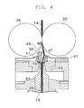
FIG. 4 is a cross-sectional view of an air-jet spinning device. - A fine spinning machine (spinning machine) as a yarn winding machine according to one embodiment of the present invention will be described with reference to the drawings. As illustrated in
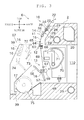
FIG. 1 , a fine spinning machine 1 includes a machinemain body 2, adrive end box 3, a bobbin stocker (bobbin stocking device) 4, and ablower box 5. - In the machine
main body 2, a plurality of spinning units (yarn winding units) 6 are arranged in line along a longitudinal direction thereof. As illustrated inFIG. 3 , each spinningunit 6 includes adraft device 10, aspinning section 11, ayarn accumulating device 12, and a windingsection 13, arranged in this order from upstream to downstream. "Upstream" and "downstream" respectively refer to upstream and downstream in a travelling direction of afiber bundle 14 and a spunyarn 15 at the time of spinning. Eachspinning unit 6 is adapted to spin thefiber bundle 14 supplied from thedraft device 10 by thespinning section 11 to produce the spunyarn 15, and winds the spunyarn 15 around a windingbobbin 16 with the windingsection 13. The windingbobbin 16 wound with the spunyarn 15 is referred to as apackage 17. - In the following description, a direction in which the
spinning units 6 are arranged (a direction indicated with arrows of "right" and "left" inFIG. 1 andFIG. 2 ) may be simply referred to as a "left-right direction". A direction perpendicular to the left-right direction and a top-bottom direction (vertical direction) (a direction indicated with arrows of "front" and "back" inFIG. 1 andFIG. 3 ) may be simply referred to as a "front-back direction". As illustrated inFIG. 3 , when viewed in the left-right direction, a spunyarn 15 produced by thespinning unit 6 travels on one side of the front-back direction of the machinemain body 2. A side on which the spunyarn 15 travels when viewed from the machinemain body 2 in the front-back direction (a left side inFIG. 3 ) may be referred to as a front side and an opposite side thereof may be referred to as a back side. - The
drive end box 3 is arranged at one end in the left-right direction of the machinemain body 2. A driving source or the like adapted to reciprocate a traverse mechanism 60 (described later) is arranged in thedrive end box 3. Compressed air is supplied to thedrive end box 3 from a compressed air source (not illustrated) via a compressedair supplying pipe 33. A regulator or the like adapted to appropriately adjust the compressed air and supply the compressed air to each section of the fine spinning machine 1 is arranged in thedrive end box 3. The compressed air adjusted to an appropriate air pressure by the regulator or the like is supplied to each section of the fine spinning machine 1 via a duct, a tube, or the like (not illustrated). - As illustrated in
FIG. 1 , anoperation section 18 is arranged on a front side of thedrive end box 3. Theoperation section 18 includes a display screen capable of displaying information related to eachspinning unit 6, a setting operation tool (an operation button and/or an operation dial and the like) for carrying out various types of settings, and the like. Theoperation section 18 can communicate with each spinningunit 6, and collectively manages information related to the plurality of spinningunits 6 of the fine spinning machine 1. Theoperation section 18 can transmit a control signal collectively or individually to the plurality of spinningunits 6 in the fine spinning machine 1. Therefore, the operator of the fine spinning machine 1 can collectively operate the plurality of spinningunits 6 by theoperation section 18. - The
bobbin stocker 4 is arranged at an end in the left-right direction of the machinemain body 2 which is opposite to the end at which thedrive end box 3 is provided. Thebobbin stocker 4 can stock a plurality of empty windingbobbins 16. - As illustrated in
FIG. 2 , theblower box 5 is arranged on a back side of thebobbin stocker 4. A negative pressure source (not illustrated) is provided in theblower box 5. As illustrated inFIG. 3 ,negative pressure ducts main body 2. Thenegative pressure ducts negative pressure ducts negative pressure ducts - The
draft device 10 is arranged in proximity to an upper end of the machinemain body 2. Thedraft device 10 drafts a sliver (a material of the fiber bundle) 22 supplied from a sliver case (not illustrated) via a sliver guide until a predetermined width is obtained. - The
draft device 10 includes a plurality of draft rollers. Two draft rollers as one set form a draft roller pair. Thedraft device 10 is a so-called four line draft device including four draft roller pairs, i.e., aback roller pair 23 and 27, athird roller pair 24 and 28, amiddle roller pair front roller pair FIG. 3 , the top rollers are, in the order from the upstream, a back top roller 23, a third top roller 24, a middletop roller 25 provided with a rubber apron belt, and a fronttop roller 26. The bottom rollers are, in the order from the upstream, aback bottom roller 27, a thirdbottom roller 28, amiddle bottom roller 29 provided with a rubber apron belt, and afront bottom roller 30. - Each of the
bottom rollers top rollers top rollers respective bottom rollers - The
draft device 10 can sandwich thesliver 22 between the rotatingtop rollers bottom rollers sliver 22 towards the downstream. In thedraft device 10, a rotation speed of the downstream draft roller pair is faster. Therefore, the fiber bundle 14 (or the sliver 22) is drafted while being transported between the draft roller pair and the draft roller pair. A degree to which thefiber bundle 14 is drafted can be changed by appropriately setting the rotation speed of each of thebottom rollers draft device 10 can draft thefiber bundle 14 into a desired fiber width. The rotation speed of each roller is appropriately changed according to a type of fibers and a spinning condition (a winding condition) such as a thickness of the spunyarn 15. - The
spinning section 11 is arranged immediately downstream of thefront roller pair fiber bundle 14 drafted by thedraft device 10 is supplied to thespinning section 11. Thespinning section 11 includes an air-jet spinning device 41 adapted to apply twists to thefiber bundle 14 using a whirling airflow. The air-jet spinning device 41 twists thefiber bundle 14 supplied from thedraft device 10 to produce the spunyarn 15. - As illustrated in
FIG. 4 , the air-jet spinning device 41 includes anozzle block 43, a hollowguide shaft body 44, and afiber guiding section 45. - A spinning
chamber 46 is formed between thenozzle block 43 and the hollowguide shaft body 44. Thenozzle block 43 is provided with anair ejecting nozzle 47 for ejecting air into the spinningchamber 46. An introducingport 48 for introducing thefiber bundle 14 into the spinningchamber 46 is formed in thefiber guiding section 45. Theair ejecting nozzle 47 is adapted to eject the air into the spinningchamber 46 to generate the whirling airflow. Thefiber bundle 14 supplied from thedraft device 10 is guided into the spinningchamber 46 by thefiber guiding section 45 having the introducingport 48. In the spinningchamber 46, fibers of thefiber bundle 14 are swung around the hollowguide shaft body 44 by the whirling airflow, and the twists are applied to thefiber bundle 14. Accordingly, the spunyarn 15 is produced. The twisted spunyarn 15 is passed through ayarn passage 49 formed through an axial center of the hollowguide shaft body 44, and fed to an outside of the air-jet spinning device 41 from a downstream yarn exit (not illustrated). - A needle-
like guide needle 50 is arranged in the introducingport 48. A tip of theguide needle 50 is directed towards the spinningchamber 46. Thefiber bundle 14 introduced from theyarn introducing port 48 is guided into the spinningchamber 46 via theguide needle 50. Accordingly, a state of thefiber bundle 14 introduced into the spinningchamber 46 can be stabilized. Since thefiber bundle 14 is guided so as to be wound around theguide needle 50, even if twists are applied to the fibers in the spinningchamber 46, the twists are prevented from being propagated to the upstream of thefiber guiding section 45. Accordingly, the twists applied by thespinning section 11 are prevented from influencing thedraft device 10. Theguide needle 50 may be omitted, and a downstream end of thefiber guiding section 45 may function as theguide needle 50. - The winding
section 13 is arranged downstream of thespinning section 11 and in a lower range of the machinemain body 2. The windingsection 13 includes acradle arm 58 and a windingdrum 59. Thecradle arm 58 is supported to be swingable about a supportingshaft 57. Thecradle arm 58 can rotatably support a windingbobbin 16 for winding the spunyarn 15. The windingdrum 59 is adapted to be driven while making contact with an outer peripheral surface of the windingbobbin 16 or an outer peripheral surface of thepackage 17. The windingdrum 59 is driven by an electric motor (not illustrated) to rotate the winding bobbin 16 (or the package 17) making contact with the windingdrum 59, and the spunyarn 15 can be wound around the windingbobbin 16. - As illustrated in
FIG. 1 , the fine spinning section 1 includes thetraverse mechanism 60 adapted to traverse the spunyarn 15 to be wound by the windingsection 13 of eachspinning unit 6 in the lower range of the machinemain body 2. Thetraverse mechanism 60 includes a plurality of traverse guides 61 and atraverse rod 62. - Each of the traverse guides 61 is arranged in proximity to the winding
section 13 of eachspinning unit 6, and is adapted to be engaged with the spunyarn 15 wound by the windingsection 13. Thetraverse rod 62 is arranged such that a longitudinal direction thereof is in the left-right direction, and is arranged over all thespinning units 6 of the fine spinning machine 1. Eachtraverse guide 61 is fixed to thetraverse rod 62. Thetraverse rod 62 is reciprocated left and right by a driving source (not illustrated) in thedrive end box 3. Accordingly, thetraverse guide 61 can be reciprocated all at once in all thespinning units 6. By rotating the windingbobbin 16 by the windingsection 13 while reciprocating thetraverse guide 61 engaged with the spunyarn 15, the spunyarn 15 can be wound while being traversed to form thepackage 17 of an appropriate shape. - The
yarn accumulating device 12 is arranged between the spinningsection 11 and the windingsection 13. As illustrated inFIG. 3 , theyarn accumulating device 12 includes ayarn accumulating roller 63 and anelectric motor 64 for rotatably driving theyarn accumulating roller 63. - The
yarn accumulating roller 63 can have a prescribed amount of the spunyarn 15 wound around an outer peripheral surface thereof to temporarily accumulate the spunyarn 15. When theyarn accumulating roller 63 is rotated at a predetermined rotation speed with the spunyarn 15 wound around the outer peripheral surface of theyarn accumulating roller 63, the spunyarn 15 can be pulled out at a predetermined speed from the air-jet spinning device 41 of thespinning section 11 and transported towards the downstream. Since the spunyarn 15 is temporarily accumulated on the outer peripheral surface of theyarn accumulating roller 63, theyarn accumulating device 12 can function as one type of a buffer. Accordingly, a drawback (e.g., slackening of the spunyarn 15 or the like) when a spinning speed in thespinning section 11 and a winding speed in the windingsection 13 do not match for some reason can be resolved. - A yarn
quality measuring device 65 is arranged at a position between the spinningsection 11 and theyarn accumulating device 12. The spunyarn 15 spun by thespinning section 11 is passed through the yarnquality measuring device 65 before being wound by theyarn accumulating device 12. The yarnquality measuring device 65 monitors a thickness of the travelling spunyarn 15 with a capacitance sensor (not illustrated). When a yarn defect (an area where an abnormality is found in thickness or the like of the spun yarn 15) of the spunyarn 15 is detected, the yarnquality measuring device 65 transmits a yarn defect detection signal to a unit controller (not illustrated). The yarnquality measuring device 65 is not limited to the capacitance sensor and may be a light transmissive sensor to monitor a thickness of the spunyarn 15. The yarnquality measuring device 65 may detect a foreign substance contained in the spunyarn 15 as a yarn defect. - A cutter (not illustrated) is arranged in proximity to the yarn
quality measuring device 65, and immediately cuts the spunyarn 15 when the yarn defect of the spunyarn 15 is detected. Instead of using the cutter, thespinning unit 6 may stop the supply of the air to thespinning section 11 and cut the spunyarn 15 by interrupting the production of the spunyarn 15. - As illustrated in
FIG. 1 and the like, the fine spinning machine 1 includes ayarn joining cart 66 and a doffing cart (an operation cart) 67. - A yarn joining
cart travelling rail 68 is laid along the left-right direction in the machinemain body 2. The yarn joiningcart travelling rail 68 is located on the back side of a yarn path of the spunyarn 15. Theyarn joining cart 66 can travel along the yarn joiningcart travelling rail 68. - As illustrated in
FIG. 1 andFIG. 3 , theyarn joining cart 66 includes ayarn joining device 69, asuction pipe 70, and asuction mouth 71. When the spunyarn 15 between the spinningsection 11 and the windingsection 13 is disconnected due to a yarn breakage or a yarn cut in acertain spinning unit 6, theyarn joining cart 66 travels on the yarn joiningcart travelling rail 68 to therelevant spinning unit 6 and stops. Thesuction pipe 70 sucks and catches the yarn end fed from thespinning section 11 while swinging vertically with a shaft as a center and guides the yarn end to theyarn joining device 69. Thesuction mouth 71 sucks and catches the yarn end from thepackage 17 supported by the windingsection 13 while swinging vertically with a shaft as a center and guides the yarn end to theyarn joining device 69. Theyarn joining device 69 performs a yarn joining operation by twisting the guided yarn ends by the whirling airflow generated by the compressed air. The spunyarn 15 between the spinningsection 11 and the windingsection 13 is thereby connected, and the winding of the spunyarn 15 into thepackage 17 can be resumed. - As described above, since the yarn joining
cart travelling rail 68 is laid on the back side of the yarn path, theyarn joining cart 66 travels on the back side of the yarn path and performs the yarn joining operation from a position on the back side. Since theyarn joining cart 66 is located on the back side of the yarn path (i.e., a receded position in the machine main body 2), maintenance is difficult to be carried out on theyarn joining cart 66. In the fine spinning machine 1 of the present embodiment, theyarn joining cart 66 can be taken out from the back side of the machinemain body 2. More specifically, as illustrated inFIG. 3 , thenegative pressure ducts yarn joining cart 66, and are not arranged on the back side of theyarn joining cart 66. Anopening 110 communicating with a space where theyarn joining cart 66 performs the yarn joining operation is formed at a portion in the back side of the machinemain body 2. Theyarn joining cart 66 thus can be installed to or removed from the machinemain body 2 via theopening 110. Therefore, theyarn joining cart 66 can be taken out from the back side of the machinemain body 2 to carry out the maintenance. - When carrying out maintenance on the
yarn joining cart 66, if access can be made to the back side of theyarn joining cart 66, sufficient maintenance may be carried out. In such a case, the maintenance operation can be carried out via theopening 110 with theyarn joining cart 66 installed in the machinemain body 2. Therefore, an opened area of theopening 110 may not be formed to a size to a degree which enables theyarn joining cart 66 to be taken out, and the opened area is sufficient to be formed to a degree enabling the operator to carry out the maintenance. - A doffing cart travelling rail (travelling path) 39 is laid along the left-right direction on the front side of the machine
main body 2. The doffingcart 67 can travel along the doffingcart travelling rail 39. - The doffing
cart 67 performs a doffing operation of the fully-wound package 17, and a bobbin setting operation for supplying an empty windingbobbin 16. As illustrated inFIG. 1 andFIG. 3 , the doffingcart 67 includes an empty bobbinaccommodating section 38, acradle operating arm 72, a yarn pull-outarm 73, and an emptybobbin supplying arm 74. The empty bobbinaccommodating section 38 can accommodate a plurality of empty windingbobbins 16. The yarn pull-outarm 73 can be extended or contracted by an air cylinder mechanism (not illustrated). A catching section configured as an air sucker device is arranged at a distal end of the yarn pull-outarm 73. The catching section is adapted to generate a suction airflow to suck and catch the spunyarn 15. A cutter (not illustrated) for cutting the spunyarn 15 sucked and caught by the catching section is arranged at the distal end of the yarn pull-outarm 73. - First, the doffing operation will be described. When the
package 17 being wound in aspinning unit 6 becomes fully wound, the doffingcart 67 travels on the doffingcart travelling rail 39 to therelevant spinning unit 6 and stops. Thecradle operating arm 72 then operates thecradle arm 58 of thespinning unit 6 to remove the fully-wound package 17 from thecradle arm 58. The removed fully woundpackage 17 is dropped onto and received by apackage conveyor 75 laid between the spinningunit 6 and the doffingcart travelling rail 39. The doffingcart 67 may include a conveying mechanism such that the fully-wound package 17 is conveyed from the windingsection 13 to thepackage conveyor 75 by the conveying mechanism. As illustrated inFIG. 2 , thepackage conveyor 75 is arranged along the left-right direction. Thepackage conveyor 75 conveys the fully-wound package 17 along the left-right direction. A package collecting section (not illustrated) is arranged at an end in the conveying direction of the fully-wound package 17 by thepackage conveyor 75. By the doffing operation described above, the fully-wound package 17 can be automatically collected. - Next, the bobbin setting operation will be described. The doffing
cart 67 clamps the empty windingbobbin 16 stocked in the empty bobbinaccommodating section 38 with the emptybobbin supplying arm 74, and swings the emptybobbin supplying arm 74 to set the windingbobbin 16 to thecradle arm 58 of thespinning unit 6. Before or after this operation, the yarn pull-outarm 73 of the doffingcart 67 sucks and catches the spunyarn 15 spun by thespinning section 11, and guides the caught spunyarn 15 to proximity of the empty windingbobbin 16 held by thecradle arm 58. Under this state, the spunyarn 15 pulled out from thespinning section 11 is fixed to the windingbobbin 16 by a method such as a known bunch winding. - After the bunch winding is completed, the doffing
cart 67 operates the cutter to cut the spunyarn 15 sucked and caught by the catching section of the yarn pull-outarm 73. The spunyarn 15 remaining from the bunch winding thus can be cut, and sucked and removed by the suction airflow of the catching section. The doffingcart 67 includes a yarn waste collecting box (yarn waste collecting section) 78 adapted to collect yarn wastes sucked and removed by the yarn pull-outarm 73. The yarnwaste collecting box 78 includes an air filter (not illustrated), which can separate the suction airflow generated by the catching section and the yarn waste blown away on the suction airflow such that only the yarn wastes are collected. - After the bobbin setting operation of the doffing
cart 67 described above is finished, the windingsection 13 of thespinning unit 6 starts the rotation of the windingbobbin 16 while the spunyarn 15 pulled out from thespinning section 11 is fixed to the windingbobbin 16. The winding of the spunyarn 15 with respect to the new windingbobbin 16 thus can be started. - Since the number of empty winding
bobbins 16 that can be stocked in the empty bobbinaccommodating section 38 of the doffingcart 67 is limited, the windingbobbin 16 is required to be restocked at an appropriate timing. The doffingcart 67 receives the supply of the windingbobbin 16 from thebobbin stocker 4 at an appropriate timing. As illustrated inFIG. 2 , the doffingcart travelling rail 39 is laid to a bobbin supplying position 77 (a position illustrated with a chain double-dashed line inFIG. 1 andFIG. 2 ). As illustrated inFIG. 1 andFIG. 2 , thebobbin supplying position 77 is located on the front side of the machinemain body 2, and is arranged adjacent to thebobbin stocker 4. The doffingcart 67 travels to thebobbin supplying position 77 and stops, as necessary. The windingbobbin 16 is supplied from thebobbin stocker 4 to the doffingcart 67 stopped at thebobbin supplying position 77. - As illustrated in
FIG. 2 , anoperation passage 80 for the operator to pass is provided on the front side of the doffingcart travelling rail 39. In theoperation passage 80, the operator can check a state of the front side of the fine spinning machine 1. From theoperation passage 80, the operator can carry out the maintenance operation and the like of thespinning units 6 arranged on the front side of the fine spinning machine 1. - Next, a structure of the
bobbin stocker 4 will be described. - The
bobbin stocker 4 includes a plurality ofpegs 81 for stocking the windingbobbins 16. Thepeg 81 is a rod-shaped member. As is well known, the windingbobbin 16 for winding the spunyarn 15 is a tubular body, and the windingbobbin 16 can be set on thepeg 81 such that thepeg 81 is located inside the windingbobbin 16. - The
bobbin stocker 4 stocks a plurality of the windingbobbins 16 such than an axial end of the windingbobbins 16 faces towards theoperation passage 80. A longitudinal direction of each peg 81 is arranged along the substantially front-back direction, and a distal end of each peg 81 is arranged to face the front side. Therefore, by setting the windingbobbin 16 on thepeg 81, the windingbobbin 16 can be supported under a state in which an axial line of the windingbobbin 16 is positioned substantially horizontal. Since thebobbin stocker 4 stocks the windingbobbin 16 while maintaining the horizontal posture, the windingbobbins 16 can be accommodated in a space efficient manner. - The front side of the
bobbin stocker 4 is opened. The distal end of each peg 81 is exposed to the front side of thebobbin stocker 4. In the fine spinning machine 1 of the present embodiment, thebobbin stocker 4 is arranged facing the front side. A state of the windingbobbins 16 stocked in thebobbin stocker 4 can be checked from theoperation passage 80. The operator can easily check the remaining amount and the like of the windingbobbins 16 in thebobbin stocker 4 from theoperation passage 80. Since thepeg 81 is facing the front side, the windingbobbins 16 can be set to thepegs 81 from theoperation passage 80. Accordingly, a restocking operation of the windingbobbins 16 with respect to thebobbin stocker 4 can be easily carried out. In the fine spinning machine 1 of the present embodiment, the windingbobbins 16 stocked in thebobbin stocker 4 can be easily accessed from the front side (from the operation passage 80). - The
bobbin stocker 4 includes anendless chain 82 driven to circulate within a plane substantially orthogonal to the longitudinal direction of the pegs 81 (a perpendicular plane) . The plurality of thepegs 81 are fixed to theendless chain 82. When theendless chain 82 is continuously or intermittently driven to circulate towards one direction, the windingbobbins 16 set on thepegs 81 can be fed along a longitudinal direction of theendless chain 82. - A
bobbin detaching section 83 is arranged in a middle of a feeding path of the windingbobbin 16 in thebobbin stocker 4. Thebobbin detaching section 83 includes a detachment lever (not illustrated) capable of making contact with the windingbobbin 16 set on thepeg 81, and the windingbobbin 16 can be detached from thepeg 81 by the detachment lever. - The winding
bobbin 16 detached from thepeg 81 by thebobbin detaching section 83 is dropped onto abobbin guiding passage 84. Thebobbin guiding passage 84 connects thebobbin detaching section 83 and abobbin supplying section 85. The windingbobbin 16 dropped onto thebobbin guiding passage 84 is guided to thebobbin supplying section 85 through thebobbin guiding passage 84. Thebobbin guiding passage 84 is curved, and changes a direction of the windingbobbin 16 passing through thebobbin guiding passage 84. When the windingbobbin 16 is detached from thepeg 81, the axial line of the windingbobbin 16 is facing in the front-back direction, but the direction is changed while passing through thebobbin guiding passage 84. When the windingbobbin 16 reaches thebobbin supplying section 85, the axial line of the windingbobbin 16 is facing in a substantially left-right direction. - The
bobbin supplying section 85 is formed immediately above the doffingcart 67 stopped at thebobbin supplying position 77. Thebobbin supplying section 85 includes a bobbin feeding mechanism (not illustrated). The bobbin feeding mechanism can stop the windingbobbins 16 guided through thebobbin guiding passage 84, and can feed the stopped windingbobbins 16 one at a time. The fed windingbobbin 16 is dropped from thebobbin supplying section 85. - With the above structure, the winding
bobbins 16 can be supplied to the doffingcart 67 stopped at thebobbin supplying position 77. - As described above, in the fine spinning machine 1 of the present embodiment, the position where the doffing
cart 67 receives the supply of the windingbobbins 16 from the bobbin stocker 4 (the bobbin supplying position 77) is set on the front side of the machinemain body 2. Thebobbin stocker 4 is facing the front side, and the windingbobbins 16 stocked in thebobbin stocker 4 can be accessed from the front side. By arranging the front side of thebobbin stocker 4 and thebobbin supplying position 77 on the same side, a structure for supplying the windingbobbins 16 stocked in thebobbin stocker 4 to the doffing cart 67 (thebobbin guiding passage 84 or the like) can be made short and simple. - For example, as described in Patent Document 1, in the conventional fine spinning machine, in order to carry out maintenance on the yarn joining cart (the operation cart), the yarn joining cart is taken out from the side of the machine main body. In the conventional spinning machine, the bobbin stocker arranged at the side of the machine main body is required to be arranged so as not to interfere with the take-out passage of the yarn joining cart. In the conventional fine spinning machine, the bobbin stocker is arranged on a front side or a back side of the take-out passage. Since there is no sufficient space for arranging the bobbin stocker on the front side of the take-out passage, the bobbin stocker is inevitably arranged on the back side of the take-out passage.
- In the fine spinning machine 1 of the present embodiment, as described above, the
yarn joining cart 66 is taken out from the back side of the machinemain body 2 to carry out the maintenance. According to the structure of the present embodiment, theyarn joining cart 66 is not required to be taken out from the side of the machinemain body 2. The fine spinning machine 1 of the present embodiment does not have a restriction of arranging thebobbin stocker 4 avoiding the take-out passage of theyarn joining cart 66. Thus, in the fine spinning machine 1 of the present embodiment, thebobbin stocker 4 can be arranged facing the front side. - Since there is no restriction on the arrangement of the
bobbin stocker 4 in the present embodiment, thebobbin stocker 4 is arranged closer to the front side. The space on the back side of thebobbin stocker 4 thus can be effectively used, and as a result, theblower box 5 can be arranged on the back side and a rational arrangement is enabled. By arranging thebobbin stocker 4 closer to the front side as described above, thebobbin stocker 4 can be brought closer to the doffingcart travelling rail 39. In other words, the distance between thebobbin stocker 4 and the doffingcart 67 can be reduced. Accordingly, the structure for supplying the windingbobbin 16 from thebobbin stocker 4 to the doffingcart 67 can be made short and simple. - The application of the present embodiment is not limited to the fine spinning machine 1 having the structure of taking out the
yarn joining cart 66 from the back side of the machine main body 2 (the structure of the embodiment described above). Even for the structure (the structure of Patent Document 1) of taking out theyarn joining cart 66 from the side of the machinemain body 2, the structure of the present embodiment can be applied by arranging thebobbin stocker 4 above the take-out passage of theyarn joining cart 66, for example. By arranging thebobbin stocker 4 in the above manner, theyarn joining cart 66 can be taken out from below thebobbin stocker 4, and the arrangement of thebobbin stocker 4 in the front-back direction is not restricted. Therefore, thebobbin stocker 4 can be arranged closer to the front side, and thebobbin stocker 4 can be directed towards the front side. Thus, the structure for supplying the windingbobbin 16 from thebobbin stocker 4 to the doffingcart 67 can be made short and simple. In this case, the take-out passage of theyarn joining cart 66 is formed below thebobbin stocker 4. Accordingly, the space in which thebobbin stocker 4 can accommodate the windingbobbins 16 becomes narrow in the vertical direction, and the number of windingbobbins 16 that can be accommodated in thebobbin stocker 4 decreases. - Since the fine spinning machine 1 of the present embodiment has the structure of taking out the
yarn joining cart 66 from the back side of the machinemain body 2, the passage of theyarn joining cart 66 is not restricted to be formed below thebobbin stocker 4. In the fine spinning machine 1 of the present embodiment, thebobbin stocker 4 is arranged entirely in the vertical direction of the machine main body 2 (i.e., thebobbin stocker 4 can accommodate the windingbobbin 16 entirely in the vertical direction of the machine main body 2). Thus, a large number of windingbobbins 16 can be stocked in thebobbin stocker 4. - A yarn
waste discharge section 79 is formed on the front side of thebobbin stocker 4. The yarnwaste discharge section 79 sucks and removes yarn wastes accumulated in the yarnwaste collecting box 78 of the doffingcart 67 by a suction flow. By periodically sucking and removing the yarn wastes by the yarnwaste discharge section 79, the yarnwaste collecting box 78 of the doffingcart 67 can be prevented from getting clogged. - As illustrated in
FIG. 1 , in the front-back direction, the yarnwaste discharge section 79 is arranged at a position facing the yarnwaste collecting box 78 of the doffingcart 67 stopped at thebobbin supplying position 77. The yarnwaste discharge section 79 can generate a suction airflow. In the yarnwaste collecting box 78 of the doffingcart 67, a portion facing the yarnwaste discharge section 79 is openable. The yarnwaste discharge section 79 can suck and remove the yarn wastes from the yarnwaste collecting box 78 of the doffingcart 67 stopped at thebobbin supplying position 77. - While the doffing
cart 67 is stopped at thebobbin supplying position 77 and receiving the windingbobbins 16 from thebobbin stocker 4, the yarnwaste discharge section 79 sucks and removes the yarn wastes. In the fine spinning machine 1 of the present embodiment, the supply of the windingbobbins 16 to the doffingcart 67 and the discharge of the yarn wastes from the yarnwaste collecting box 78 of the doffingcart 67 can be simultaneously carried out. Therefore, operation efficiency of the doffingcart 67 can be improved. Since the supply of the windingbobbins 16 to the doffingcart 67 is carried out as needed, the discharge of the yarn wastes from the yarnwaste collecting box 78 can also be carried out each time the windingbobbins 16 are supplied. Accordingly, the yarnwaste collecting box 78 can be reliably prevented from getting clogged by the yarn wastes. Although machine efficiency of the fine spinning machine 1 decreases, the yarnwaste discharge section 79 may be arranged in another area to discharge the yarn wastes from the yarnwaste collecting box 78. - As described above, the fine spinning machine 1 of the present embodiment includes the machine
main body 2, the plurality of thespinning units 6, thebobbin stocker 4, and the doffingcart 67. The spinningunits 6 are arranged along the longitudinal direction of the machinemain body 2. Eachspinning unit 6 is adapted to form thepackage 17 by winding the spunyarn 15 around the windingbobbin 16. Thebobbin stocker 4 is adapted to stock the windingbobbins 16 to be used by thespinning unit 6. The doffingcart 67 is provided to travel between the spinningunits 6 and thebobbin stocker 4, and adapted to supply the windingbobbins 16 to thespinning unit 6. Thebobbin stocker 4 is arranged to be accessible from at least the front side with respect to the windingbobbins 16 stocked in thebobbin stocker 4. The doffingcart 67 is adapted to receive the windingbobbins 16 stocked in thebobbin stocker 4 at thebobbin supplying position 77 located at the front side of the machinemain body 2. - The accessible side of the
bobbin stocker 4 and the position where the doffingcart 67 receives the winding bobbins 16 (the bobbin supplying position 77) are arranged on the same side. The length of the path of the windingbobbin 16 supplied from thebobbin stocker 4 to the doffingcart 67 thus can be shortened. As a result, the windingbobbin 16 can be efficiently supplied to the doffingcart 67 with a simple structure. - The fine spinning machine 1 of the present embodiment further includes the doffing
cart travelling rail 39 arranged at the front side of the machinemain body 2 and adapted to enable travelling of the doffingcart 67. Theoperation passage 80 for an operator to perform an operation is arranged on an opposite side of the doffingcart travelling rail 39 with respect to thespinning units 6 and thebobbin stocker 4. Thebobbin stocker 4 is arranged facing towards theoperation passage 80. The operator thus can easily check the stocking status of thebobbin stocker 4 from theoperation passage 80. - In the fine spinning machine 1 of the present embodiment, the
bobbin stocker 4 is adapted to stock a plurality of the windingbobbins 16 such that an axial end of the windingbobbins 16 faces towards theoperation passage 80. Thebobbin stocker 4 thus can stock a large number of windingbobbins 16. - The fine spinning machine 1 of the present embodiment further includes the yarn
waste collecting box 78 and the yarnwaste discharge section 79. The yarnwaste collecting box 78 is provided in the doffingcart 67 and adapted to collect the yarn wastes. The yarnwaste discharge section 79 is arranged near thebobbin stocker 4 and adapted to cause the yarn wastes accumulated in the yarnwaste collecting box 78 of the doffingcart 67 stopped at thebobbin supplying position 77 to be discharged from the yarnwaste collecting box 78. The doffingcart 67 can simultaneously carry out the reception of the windingbobbins 16 and the discarding of the yarn wastes at thebobbin supplying position 77. The efficiency of the entire fine spinning machine 1 thus can be improved. - The fine spinning machine 1 of the present embodiment includes the
yarn joining cart 66 adapted to perform a yarn joining operation of the spunyarn 15 at the back side than the spunyarn 15 being wound by thespinning unit 6. The machinemain body 2 includes theopening 110 adapted to connect the back side of the machinemain body 2 and the operation space of theyarn joining cart 66. Thus, maintenance can be performed on theyarn joining cart 66 from the back side of the machinemain body 2. Accordingly, since the yarn joining cart is not required to be taken out from the side of the machine for the maintenance of the yarn joining cart as in the conventional fine spinning machine, thebobbin stocker 4 can be arranged closer to the front side. - In the fine spinning machine 1 of the present embodiment, the
bobbin stocker 4 is arranged entirely in the height direction of the machinemain body 2. Since theyarn joining cart 66 is not required to be taken out from the side of the machinemain body 2, the space for taking out theyarn joining cart 66 is not required to be provided on the side of the machine. As a result, a degree of freedom in the layout of thebobbin stocker 4 can be improved, and thebobbin stocker 4 can be arranged entirely in the vertical direction of the machinemain body 2. The number of the windingbobbins 16 which can be stocked in thebobbin stocker 4 thus can be increased. - Preferred embodiments and alternative embodiments of the present invention have been described above, but the above-described structure may be modified as below.
- In the embodiments described above, the
yarn accumulating roller 63 of theyarn accumulating device 12 is rotated to pull out the spunyarn 15 from thespinning section 11. For example, as described in Japanese Unexamined Patent Publication No.2005-220484 - In the embodiments described above, the
package conveyor 75 is arranged between the spinningunit 6 and the travelling path of the doffingcart 67. Thespinning unit 6, the travelling path of the doffingcart 67, and thepackage conveyor 75 may be arranged in this order. The structure of automatically collecting the fully-wound package 17 by thepackage conveyor 75 may be omitted. In this case, a package receiving section adapted to temporarily stock the fully-wound package 17 is formed at a position where thepackage conveyor 75 is arranged in the embodiment described above. In this case, the operator manually collects the fully-wound package placed on the package receiving section. - In the embodiments described above, the doffing cart (the operation cart) 67 carries out both the doffing operation and the bobbin setting operation, but the operation cart according to the present invention is not always required to carry out the doffing operation. The operation cart may carry out only the bobbin setting operation. In this case, the fully-
wound package 17 in each windingsection 13 is collected by appropriate means different from the operation cart. - The structure of the present embodiment is not limited to the air-
jet spinning device 41, and can also be applied to a spinning machine provided with other types of spinning devices. The structure of the present embodiment is not limited to the spinning machine, and may be widely applied to other types of yarn winding machines such as an automatic winder.
Claims (6)
- A yarn winding machine comprising:a machine main body (2),a plurality of yarn winding units (6) arranged along a longitudinal direction of the machine main body (2), each yarn winding unit (6) being adapted to form a package (17) by winding a yarn (15) around a winding bobbin (16),a bobbin stocking device (4) adapted to stock winding bobbins (16) to be used by the yarn winding units (6), andan operation cart (67) provided to travel between the yarn winding units (6) and the bobbin stocking device (4), and adapted to supply the winding bobbins (16) to the yarn winding units (6),wherein provided that a direction along an arranged direction of the yarn winding units (6) is a left-right direction, a direction perpendicular to the left-right direction and a top-bottom direction is a front-back direction, and when viewed in the front-back direction of the machine main body (2), a side where yarns (15) respectively wound by the yarn winding units (6) are travelling is a front side and an opposite side is a back side,the bobbin stocking device (4) is arranged to be accessible from at least the front side with respect to the winding bobbins (16) stocked in the bobbin stocking device (4), andthe operation cart (67) is adapted to receive the winding bobbins (16) stocked in the bobbin stocking device (4) at a bobbin supplying position (77) located at the front side of the machine main body (2).
- The yarn winding machine according to claim 1, further comprising a travelling path arranged at the front side of the machine main body (2) and adapted to enable travelling of the operation cart (67),
wherein an operation passage for an operator to perform an operation is arranged on an opposite side of the travelling path with respect to the yarn winding units (6) and the bobbin stocking device (4). - The yarn winding machine according to claim 2, wherein the bobbin stocking device (4) is adapted to stock a plurality of the winding bobbins (16) such that an axial end of the winding bobbins (16) faces towards the operation passage.
- The yarn winding machine according to any one of claim 1 through claim 3, further comprising:a yarn waste collecting section (78) provided in the operation cart (67) and adapted to collect yarn wastes, anda yarn waste discharge section (79) arranged near the bobbin stocking device (4) and adapted to receive the yarn wastes discharged from the yarn waste collecting section (78) of the operation cart (67) stopped at the bobbin supplying position (77).
- The yarn winding machine according to any one of claim 1 through claim 4, further comprising a yarn joining cart (66) adapted to perform a yarn joining operation of the yarn (15) at the back side than the yarns (15) being wound by the yarn winding units (6),
wherein the machine main body (2) includes an opening (110) that connects the back side of the machine main body (2) and an operation space of the yarn joining cart (66). - The yarn winding machine according to claim 5, wherein the bobbin stocking device (4) is arranged entirely in a height direction of the machine main body (2).
Applications Claiming Priority (1)
| Application Number | Priority Date | Filing Date | Title |
|---|---|---|---|
| JP2011206231A JP2013067883A (en) | 2011-09-21 | 2011-09-21 | Yarn winder |
Publications (3)
| Publication Number | Publication Date |
|---|---|
| EP2573022A2 true EP2573022A2 (en) | 2013-03-27 |
| EP2573022A3 EP2573022A3 (en) | 2016-02-17 |
| EP2573022B1 EP2573022B1 (en) | 2017-10-11 |
Family
ID=46704480
Family Applications (1)
| Application Number | Title | Priority Date | Filing Date |
|---|---|---|---|
| EP12180661.6A Not-in-force EP2573022B1 (en) | 2011-09-21 | 2012-08-16 | Yarn winding machine |
Country Status (3)
| Country | Link |
|---|---|
| EP (1) | EP2573022B1 (en) |
| JP (1) | JP2013067883A (en) |
| CN (1) | CN103010816B (en) |
Cited By (2)
| Publication number | Priority date | Publication date | Assignee | Title |
|---|---|---|---|---|
| CN107938048A (en) * | 2017-12-20 | 2018-04-20 | 苏州鸿展工艺织造有限公司 | One kind is doffed tube ejector |
| EP3569539A1 (en) * | 2018-05-14 | 2019-11-20 | Maschinenfabrik Rieter AG | Method for storing and transporting cores on a textile machine and textile machine |
Families Citing this family (8)
| Publication number | Priority date | Publication date | Assignee | Title |
|---|---|---|---|---|
| JP2015067441A (en) * | 2013-09-30 | 2015-04-13 | 村田機械株式会社 | Work truck for textile machine |
| JP2015161032A (en) * | 2014-02-25 | 2015-09-07 | 村田機械株式会社 | Yarn storage device, yarn winding unit therewith and yarn winder therewith |
| JP2016117584A (en) * | 2014-12-24 | 2016-06-30 | 村田機械株式会社 | Textile machine |
| JP2017082370A (en) * | 2015-10-30 | 2017-05-18 | 村田機械株式会社 | Bobbin turnaround mechanism, bobbin storage device and spinning machine |
| CN105297203B (en) * | 2015-11-28 | 2017-12-05 | 江阴市华方新技术科研有限公司 | A kind of doffing dolly and the spinning machine for possessing the doffing dolly |
| JP2019119539A (en) * | 2017-12-28 | 2019-07-22 | 村田機械株式会社 | Spool machine and bobbin supply method |
| DE102019111775A1 (en) | 2019-05-07 | 2020-11-12 | Saurer Spinning Solutions Gmbh & Co. Kg | Method for controlling a service unit |
| JP2022026121A (en) * | 2020-07-30 | 2022-02-10 | 村田機械株式会社 | Yarn winder |
Citations (3)
| Publication number | Priority date | Publication date | Assignee | Title |
|---|---|---|---|---|
| US4865260A (en) | 1986-09-29 | 1989-09-12 | Savio S.P.A. | Equipment and process to supply winding tubes to the individual winding stations of a textile machine |
| JPH08246275A (en) | 1995-03-01 | 1996-09-24 | Murata Mach Ltd | Spinning machine and its maintenance flatcar |
| JP2005220484A (en) | 2004-02-06 | 2005-08-18 | Murata Mach Ltd | Textile machine |
Family Cites Families (5)
| Publication number | Priority date | Publication date | Assignee | Title |
|---|---|---|---|---|
| GB8500120D0 (en) * | 1985-01-03 | 1985-02-13 | Rieter Ag Maschf | Bobbin loading apparatus |
| JPH093736A (en) * | 1995-06-15 | 1997-01-07 | Kanebo Ltd | Stock yarn-supplying apparatus in winder |
| CZ300483B6 (en) * | 2003-09-04 | 2009-05-27 | Rieter Cz A.S. | Device for unwinding linear textile material when producing component yarn |
| JP3952025B2 (en) * | 2004-02-19 | 2007-08-01 | 村田機械株式会社 | Textile machinery |
| JP2007112533A (en) * | 2005-10-18 | 2007-05-10 | Bridgestone Corp | Bobbin fixing device |
-
2011
- 2011-09-21 JP JP2011206231A patent/JP2013067883A/en not_active Withdrawn
-
2012
- 2012-08-08 CN CN201210280860.6A patent/CN103010816B/en active Active
- 2012-08-16 EP EP12180661.6A patent/EP2573022B1/en not_active Not-in-force
Patent Citations (3)
| Publication number | Priority date | Publication date | Assignee | Title |
|---|---|---|---|---|
| US4865260A (en) | 1986-09-29 | 1989-09-12 | Savio S.P.A. | Equipment and process to supply winding tubes to the individual winding stations of a textile machine |
| JPH08246275A (en) | 1995-03-01 | 1996-09-24 | Murata Mach Ltd | Spinning machine and its maintenance flatcar |
| JP2005220484A (en) | 2004-02-06 | 2005-08-18 | Murata Mach Ltd | Textile machine |
Cited By (4)
| Publication number | Priority date | Publication date | Assignee | Title |
|---|---|---|---|---|
| CN107938048A (en) * | 2017-12-20 | 2018-04-20 | 苏州鸿展工艺织造有限公司 | One kind is doffed tube ejector |
| CN107938048B (en) * | 2017-12-20 | 2024-05-14 | 江苏鸿展新材料科技有限公司 | Doffing tube changing device |
| EP3569539A1 (en) * | 2018-05-14 | 2019-11-20 | Maschinenfabrik Rieter AG | Method for storing and transporting cores on a textile machine and textile machine |
| CN110482314A (en) * | 2018-05-14 | 2019-11-22 | 里特机械公司 | For storing and transporting the method and weaving loom of sleeve on the textile machine |
Also Published As
| Publication number | Publication date |
|---|---|
| CN103010816A (en) | 2013-04-03 |
| CN103010816B (en) | 2018-02-06 |
| EP2573022B1 (en) | 2017-10-11 |
| EP2573022A3 (en) | 2016-02-17 |
| JP2013067883A (en) | 2013-04-18 |
Similar Documents
| Publication | Publication Date | Title |
|---|---|---|
| EP2573022B1 (en) | Yarn winding machine | |
| EP2573017B1 (en) | Yarn winding unit, yarn winding apparatus and spinning machine | |
| EP2573216B1 (en) | Air-jet spinning machine and manufacturing method of spun yarn | |
| JP3952023B2 (en) | Textile machinery | |
| JP2015513009A (en) | Roving machine equipped with yarn defect detection and removal device | |
| CN109969861B (en) | Yarn winding machine and bobbin supplying method | |
| CN109385703B (en) | Rotor spinning machine | |
| JP2014125714A (en) | Spinning machine | |
| US4169350A (en) | Pneumatic spinning apparatus | |
| CN102465364A (en) | Draft roller, draft device, and spinning machine | |
| JP2017082370A (en) | Bobbin turnaround mechanism, bobbin storage device and spinning machine | |
| CN109385702B (en) | Rotor spinning machine and display control method | |
| CN109969862B (en) | Yarn winding machine | |
| JP2014009052A (en) | Textile machine | |
| CN103261497A (en) | Textile machine | |
| JP3952025B2 (en) | Textile machinery | |
| CN112442768A (en) | Management device for spinning machine and spinning machine with management device | |
| CN119082956A (en) | Sliver feeders and methods | |
| JP2017053052A (en) | Yarn winding machine | |
| CN113957574B (en) | Air spinning device, air spinning machine and spinning method | |
| CN105734741B (en) | Fiber is mechanical | |
| JP2015178688A (en) | Fiber control member, draft apparatus and spinner | |
| CN105274677B (en) | Heart yarn feedway and spinning machine | |
| EP1726695B1 (en) | Core yarn production method and apparatus | |
| CN111847101B (en) | Yarn winding machine and yarn hanging method |
Legal Events
| Date | Code | Title | Description |
|---|---|---|---|
| PUAI | Public reference made under article 153(3) epc to a published international application that has entered the european phase |
Free format text: ORIGINAL CODE: 0009012 |
|
| AK | Designated contracting states |
Kind code of ref document: A2 Designated state(s): AL AT BE BG CH CY CZ DE DK EE ES FI FR GB GR HR HU IE IS IT LI LT LU LV MC MK MT NL NO PL PT RO RS SE SI SK SM TR |
|
| AX | Request for extension of the european patent |
Extension state: BA ME |
|
| PUAL | Search report despatched |
Free format text: ORIGINAL CODE: 0009013 |
|
| AK | Designated contracting states |
Kind code of ref document: A3 Designated state(s): AL AT BE BG CH CY CZ DE DK EE ES FI FR GB GR HR HU IE IS IT LI LT LU LV MC MK MT NL NO PL PT RO RS SE SI SK SM TR |
|
| AX | Request for extension of the european patent |
Extension state: BA ME |
|
| RIC1 | Information provided on ipc code assigned before grant |
Ipc: B65H 54/26 20060101AFI20160108BHEP Ipc: B65H 67/06 20060101ALI20160108BHEP Ipc: B65H 67/04 20060101ALI20160108BHEP |
|
| 17P | Request for examination filed |
Effective date: 20160727 |
|
| RBV | Designated contracting states (corrected) |
Designated state(s): AL AT BE BG CH CY CZ DE DK EE ES FI FR GB GR HR HU IE IS IT LI LT LU LV MC MK MT NL NO PL PT RO RS SE SI SK SM TR |
|
| GRAP | Despatch of communication of intention to grant a patent |
Free format text: ORIGINAL CODE: EPIDOSNIGR1 |
|
| INTG | Intention to grant announced |
Effective date: 20170704 |
|
| GRAS | Grant fee paid |
Free format text: ORIGINAL CODE: EPIDOSNIGR3 |
|
| GRAA | (expected) grant |
Free format text: ORIGINAL CODE: 0009210 |
|
| AK | Designated contracting states |
Kind code of ref document: B1 Designated state(s): AL AT BE BG CH CY CZ DE DK EE ES FI FR GB GR HR HU IE IS IT LI LT LU LV MC MK MT NL NO PL PT RO RS SE SI SK SM TR |
|
| REG | Reference to a national code |
Ref country code: GB Ref legal event code: FG4D |
|
| REG | Reference to a national code |
Ref country code: CH Ref legal event code: EP |
|
| REG | Reference to a national code |
Ref country code: IE Ref legal event code: FG4D |
|
| REG | Reference to a national code |
Ref country code: AT Ref legal event code: REF Ref document number: 935818 Country of ref document: AT Kind code of ref document: T Effective date: 20171115 |
|
| REG | Reference to a national code |
Ref country code: DE Ref legal event code: R096 Ref document number: 602012038329 Country of ref document: DE |
|
| REG | Reference to a national code |
Ref country code: NL Ref legal event code: MP Effective date: 20171011 |
|
| REG | Reference to a national code |
Ref country code: LT Ref legal event code: MG4D |
|
| REG | Reference to a national code |
Ref country code: AT Ref legal event code: MK05 Ref document number: 935818 Country of ref document: AT Kind code of ref document: T Effective date: 20171011 |
|
| PG25 | Lapsed in a contracting state [announced via postgrant information from national office to epo] |
Ref country code: NL Free format text: LAPSE BECAUSE OF FAILURE TO SUBMIT A TRANSLATION OF THE DESCRIPTION OR TO PAY THE FEE WITHIN THE PRESCRIBED TIME-LIMIT Effective date: 20171011 |
|
| PG25 | Lapsed in a contracting state [announced via postgrant information from national office to epo] |
Ref country code: FI Free format text: LAPSE BECAUSE OF FAILURE TO SUBMIT A TRANSLATION OF THE DESCRIPTION OR TO PAY THE FEE WITHIN THE PRESCRIBED TIME-LIMIT Effective date: 20171011 Ref country code: LT Free format text: LAPSE BECAUSE OF FAILURE TO SUBMIT A TRANSLATION OF THE DESCRIPTION OR TO PAY THE FEE WITHIN THE PRESCRIBED TIME-LIMIT Effective date: 20171011 Ref country code: NO Free format text: LAPSE BECAUSE OF FAILURE TO SUBMIT A TRANSLATION OF THE DESCRIPTION OR TO PAY THE FEE WITHIN THE PRESCRIBED TIME-LIMIT Effective date: 20180111 Ref country code: ES Free format text: LAPSE BECAUSE OF FAILURE TO SUBMIT A TRANSLATION OF THE DESCRIPTION OR TO PAY THE FEE WITHIN THE PRESCRIBED TIME-LIMIT Effective date: 20171011 Ref country code: SE Free format text: LAPSE BECAUSE OF FAILURE TO SUBMIT A TRANSLATION OF THE DESCRIPTION OR TO PAY THE FEE WITHIN THE PRESCRIBED TIME-LIMIT Effective date: 20171011 |
|
| PG25 | Lapsed in a contracting state [announced via postgrant information from national office to epo] |
Ref country code: GR Free format text: LAPSE BECAUSE OF FAILURE TO SUBMIT A TRANSLATION OF THE DESCRIPTION OR TO PAY THE FEE WITHIN THE PRESCRIBED TIME-LIMIT Effective date: 20180112 Ref country code: RS Free format text: LAPSE BECAUSE OF FAILURE TO SUBMIT A TRANSLATION OF THE DESCRIPTION OR TO PAY THE FEE WITHIN THE PRESCRIBED TIME-LIMIT Effective date: 20171011 Ref country code: IS Free format text: LAPSE BECAUSE OF FAILURE TO SUBMIT A TRANSLATION OF THE DESCRIPTION OR TO PAY THE FEE WITHIN THE PRESCRIBED TIME-LIMIT Effective date: 20180211 Ref country code: AT Free format text: LAPSE BECAUSE OF FAILURE TO SUBMIT A TRANSLATION OF THE DESCRIPTION OR TO PAY THE FEE WITHIN THE PRESCRIBED TIME-LIMIT Effective date: 20171011 Ref country code: HR Free format text: LAPSE BECAUSE OF FAILURE TO SUBMIT A TRANSLATION OF THE DESCRIPTION OR TO PAY THE FEE WITHIN THE PRESCRIBED TIME-LIMIT Effective date: 20171011 Ref country code: BG Free format text: LAPSE BECAUSE OF FAILURE TO SUBMIT A TRANSLATION OF THE DESCRIPTION OR TO PAY THE FEE WITHIN THE PRESCRIBED TIME-LIMIT Effective date: 20180111 Ref country code: LV Free format text: LAPSE BECAUSE OF FAILURE TO SUBMIT A TRANSLATION OF THE DESCRIPTION OR TO PAY THE FEE WITHIN THE PRESCRIBED TIME-LIMIT Effective date: 20171011 |
|
| REG | Reference to a national code |
Ref country code: DE Ref legal event code: R097 Ref document number: 602012038329 Country of ref document: DE |
|
| PG25 | Lapsed in a contracting state [announced via postgrant information from national office to epo] |
Ref country code: DK Free format text: LAPSE BECAUSE OF FAILURE TO SUBMIT A TRANSLATION OF THE DESCRIPTION OR TO PAY THE FEE WITHIN THE PRESCRIBED TIME-LIMIT Effective date: 20171011 Ref country code: EE Free format text: LAPSE BECAUSE OF FAILURE TO SUBMIT A TRANSLATION OF THE DESCRIPTION OR TO PAY THE FEE WITHIN THE PRESCRIBED TIME-LIMIT Effective date: 20171011 Ref country code: SK Free format text: LAPSE BECAUSE OF FAILURE TO SUBMIT A TRANSLATION OF THE DESCRIPTION OR TO PAY THE FEE WITHIN THE PRESCRIBED TIME-LIMIT Effective date: 20171011 |
|
| PLBE | No opposition filed within time limit |
Free format text: ORIGINAL CODE: 0009261 |
|
| STAA | Information on the status of an ep patent application or granted ep patent |
Free format text: STATUS: NO OPPOSITION FILED WITHIN TIME LIMIT |
|
| PG25 | Lapsed in a contracting state [announced via postgrant information from national office to epo] |
Ref country code: RO Free format text: LAPSE BECAUSE OF FAILURE TO SUBMIT A TRANSLATION OF THE DESCRIPTION OR TO PAY THE FEE WITHIN THE PRESCRIBED TIME-LIMIT Effective date: 20171011 Ref country code: IT Free format text: LAPSE BECAUSE OF FAILURE TO SUBMIT A TRANSLATION OF THE DESCRIPTION OR TO PAY THE FEE WITHIN THE PRESCRIBED TIME-LIMIT Effective date: 20171011 Ref country code: SM Free format text: LAPSE BECAUSE OF FAILURE TO SUBMIT A TRANSLATION OF THE DESCRIPTION OR TO PAY THE FEE WITHIN THE PRESCRIBED TIME-LIMIT Effective date: 20171011 Ref country code: PL Free format text: LAPSE BECAUSE OF FAILURE TO SUBMIT A TRANSLATION OF THE DESCRIPTION OR TO PAY THE FEE WITHIN THE PRESCRIBED TIME-LIMIT Effective date: 20171011 |
|
| 26N | No opposition filed |
Effective date: 20180712 |
|
| PG25 | Lapsed in a contracting state [announced via postgrant information from national office to epo] |
Ref country code: SI Free format text: LAPSE BECAUSE OF FAILURE TO SUBMIT A TRANSLATION OF THE DESCRIPTION OR TO PAY THE FEE WITHIN THE PRESCRIBED TIME-LIMIT Effective date: 20171011 |
|
| PG25 | Lapsed in a contracting state [announced via postgrant information from national office to epo] |
Ref country code: MC Free format text: LAPSE BECAUSE OF FAILURE TO SUBMIT A TRANSLATION OF THE DESCRIPTION OR TO PAY THE FEE WITHIN THE PRESCRIBED TIME-LIMIT Effective date: 20171011 |
|
| GBPC | Gb: european patent ceased through non-payment of renewal fee |
Effective date: 20180816 |
|
| PG25 | Lapsed in a contracting state [announced via postgrant information from national office to epo] |
Ref country code: LU Free format text: LAPSE BECAUSE OF NON-PAYMENT OF DUE FEES Effective date: 20180816 |
|
| REG | Reference to a national code |
Ref country code: BE Ref legal event code: MM Effective date: 20180831 |
|
| REG | Reference to a national code |
Ref country code: IE Ref legal event code: MM4A |
|
| PG25 | Lapsed in a contracting state [announced via postgrant information from national office to epo] |
Ref country code: IE Free format text: LAPSE BECAUSE OF NON-PAYMENT OF DUE FEES Effective date: 20180816 |
|
| PG25 | Lapsed in a contracting state [announced via postgrant information from national office to epo] |
Ref country code: FR Free format text: LAPSE BECAUSE OF NON-PAYMENT OF DUE FEES Effective date: 20180831 Ref country code: BE Free format text: LAPSE BECAUSE OF NON-PAYMENT OF DUE FEES Effective date: 20180831 |
|
| PG25 | Lapsed in a contracting state [announced via postgrant information from national office to epo] |
Ref country code: GB Free format text: LAPSE BECAUSE OF NON-PAYMENT OF DUE FEES Effective date: 20180816 |
|
| PGFP | Annual fee paid to national office [announced via postgrant information from national office to epo] |
Ref country code: DE Payment date: 20190822 Year of fee payment: 8 Ref country code: CZ Payment date: 20190724 Year of fee payment: 8 |
|
| PG25 | Lapsed in a contracting state [announced via postgrant information from national office to epo] |
Ref country code: MT Free format text: LAPSE BECAUSE OF NON-PAYMENT OF DUE FEES Effective date: 20180816 |
|
| PGFP | Annual fee paid to national office [announced via postgrant information from national office to epo] |
Ref country code: CH Payment date: 20190821 Year of fee payment: 8 |
|
| PG25 | Lapsed in a contracting state [announced via postgrant information from national office to epo] |
Ref country code: TR Free format text: LAPSE BECAUSE OF FAILURE TO SUBMIT A TRANSLATION OF THE DESCRIPTION OR TO PAY THE FEE WITHIN THE PRESCRIBED TIME-LIMIT Effective date: 20171011 |
|
| PG25 | Lapsed in a contracting state [announced via postgrant information from national office to epo] |
Ref country code: HU Free format text: LAPSE BECAUSE OF FAILURE TO SUBMIT A TRANSLATION OF THE DESCRIPTION OR TO PAY THE FEE WITHIN THE PRESCRIBED TIME-LIMIT; INVALID AB INITIO Effective date: 20120816 Ref country code: PT Free format text: LAPSE BECAUSE OF FAILURE TO SUBMIT A TRANSLATION OF THE DESCRIPTION OR TO PAY THE FEE WITHIN THE PRESCRIBED TIME-LIMIT Effective date: 20171011 |
|
| PG25 | Lapsed in a contracting state [announced via postgrant information from national office to epo] |
Ref country code: MK Free format text: LAPSE BECAUSE OF NON-PAYMENT OF DUE FEES Effective date: 20171011 Ref country code: CY Free format text: LAPSE BECAUSE OF FAILURE TO SUBMIT A TRANSLATION OF THE DESCRIPTION OR TO PAY THE FEE WITHIN THE PRESCRIBED TIME-LIMIT Effective date: 20171011 |
|
| PG25 | Lapsed in a contracting state [announced via postgrant information from national office to epo] |
Ref country code: AL Free format text: LAPSE BECAUSE OF FAILURE TO SUBMIT A TRANSLATION OF THE DESCRIPTION OR TO PAY THE FEE WITHIN THE PRESCRIBED TIME-LIMIT Effective date: 20171011 |
|
| REG | Reference to a national code |
Ref country code: DE Ref legal event code: R119 Ref document number: 602012038329 Country of ref document: DE |
|
| REG | Reference to a national code |
Ref country code: CH Ref legal event code: PL |
|
| PG25 | Lapsed in a contracting state [announced via postgrant information from national office to epo] |
Ref country code: LI Free format text: LAPSE BECAUSE OF NON-PAYMENT OF DUE FEES Effective date: 20200831 Ref country code: CZ Free format text: LAPSE BECAUSE OF NON-PAYMENT OF DUE FEES Effective date: 20200816 Ref country code: CH Free format text: LAPSE BECAUSE OF NON-PAYMENT OF DUE FEES Effective date: 20200831 |
|
| PG25 | Lapsed in a contracting state [announced via postgrant information from national office to epo] |
Ref country code: DE Free format text: LAPSE BECAUSE OF NON-PAYMENT OF DUE FEES Effective date: 20210302 |