JP2015178688A - Fiber control member, draft apparatus and spinner - Google Patents
Fiber control member, draft apparatus and spinner Download PDFInfo
- Publication number
- JP2015178688A JP2015178688A JP2014056396A JP2014056396A JP2015178688A JP 2015178688 A JP2015178688 A JP 2015178688A JP 2014056396 A JP2014056396 A JP 2014056396A JP 2014056396 A JP2014056396 A JP 2014056396A JP 2015178688 A JP2015178688 A JP 2015178688A
- Authority
- JP
- Japan
- Prior art keywords
- draft
- control member
- fiber
- roller
- fiber control
- Prior art date
- Legal status (The legal status is an assumption and is not a legal conclusion. Google has not performed a legal analysis and makes no representation as to the accuracy of the status listed.)
- Pending
Links
Images


Classifications
-
- D—TEXTILES; PAPER
- D01—NATURAL OR MAN-MADE THREADS OR FIBRES; SPINNING
- D01H—SPINNING OR TWISTING
- D01H5/00—Drafting machines or arrangements ; Threading of roving into drafting machine
- D01H5/18—Drafting machines or arrangements without fallers or like pinned bars
- D01H5/20—Drafting machines or arrangements without fallers or like pinned bars in which fibres are controlled by contact with stationary or reciprocating surfaces
-
- D—TEXTILES; PAPER
- D01—NATURAL OR MAN-MADE THREADS OR FIBRES; SPINNING
- D01H—SPINNING OR TWISTING
- D01H13/00—Other common constructional features, details or accessories
- D01H13/04—Guides for slivers, rovings, or yarns; Smoothing dies
-
- D—TEXTILES; PAPER
- D01—NATURAL OR MAN-MADE THREADS OR FIBRES; SPINNING
- D01H—SPINNING OR TWISTING
- D01H5/00—Drafting machines or arrangements ; Threading of roving into drafting machine
- D01H5/18—Drafting machines or arrangements without fallers or like pinned bars
- D01H5/60—Arrangements maintaining drafting elements free of fibre accumulations
Abstract
Description
本発明は、主要には、ドラフト装置に設けられ、ドラフトローラ対がドラフトする繊維束を湾曲させる繊維制御部材に関する。 The present invention mainly relates to a fiber control member that is provided in a draft device and curves a fiber bundle drafted by a draft roller pair.
短繊維の含有率が高い原料をドラフトする場合、隣り合うドラフトローラ対の間に、スライバの搬送経路を湾曲させる繊維制御部材を配置することがある。繊維制御部材を配置することで、ドラフトされる繊維(スライバ)がドラフトローラ対から脱落することを防止できる。また、繊維制御部材を配置することで、ドラフト比(繊維が引き伸ばされる比率)を大きくすることができるので、太いスライバを用いてドラフトを行うことができる。太いスライバを用いる場合、原料の調達が容易になるとともに、生産効率を向上させることができる。 When drafting a raw material having a high content of short fibers, a fiber control member that curves the sliver conveyance path may be disposed between adjacent pairs of draft rollers. By arranging the fiber control member, it is possible to prevent the drafted fiber (sliver) from falling off the draft roller pair. Further, by arranging the fiber control member, it is possible to increase the draft ratio (ratio at which the fiber is stretched), and therefore it is possible to perform the draft using a thick sliver. When a thick sliver is used, it is possible to easily procure raw materials and improve production efficiency.
特許文献1は、この種の繊維制御部材を備えたドラフト装置を開示する。特許文献1では、バックローラ対とサードローラ対との間、又は、バックローラ対とセカンドローラ対との間に、繊維制御部材(繊維走行制御部材)を備える技術が開示されている。また、特許文献1では、繊維制御部材の形状を棒状の円柱とし、本体フレームに取り付ける旨が記載されている。
しかし、スライバが走行する際にスライバが繊維制御部材に擦られることで、綿カスや短繊維が若干は脱落するため、繊維制御部材の近傍に風綿が堆積することがある。特許文献1では、繊維制御部材の機能及び位置について開示するにとどまり、堆積した風綿をどのように除去するかについては記載されていない。
However, when the sliver travels, the sliver rubs against the fiber control member, so that some cotton dust and short fibers fall off, so that fluff may accumulate near the fiber control member. In
本発明の主要な目的は、堆積した風綿を効果的に除去する機能を有する繊維制御部材を提供することにある。 A main object of the present invention is to provide a fiber control member having a function of effectively removing accumulated fluff.
本発明の第1の観点によれば、以下の構成の繊維制御部材が提供される。即ち、この繊維制御部材の端部には、ドラフトローラ対がドラフトする繊維束の搬送経路を曲げる繊維束湾曲部が形成されている。前記繊維束湾曲部が形成されている部分を第1端部と称し、当該繊維束湾曲部の反対に位置する部分を第2端部と称したときに、前記第2端部には、前記第1端部に向かって切り欠かれた切欠きが形成されている。 According to the 1st viewpoint of this invention, the fiber control member of the following structures is provided. That is, a fiber bundle bending portion that bends the conveyance path of the fiber bundle that is drafted by the draft roller pair is formed at the end of the fiber control member. When the portion where the fiber bundle bending portion is formed is referred to as a first end portion, and when the portion located opposite to the fiber bundle bending portion is referred to as a second end portion, the second end portion includes the A notch cut out toward the first end is formed.
これにより、ドラフト時に発生した風綿が切欠きから落下するため、繊維制御部材及びドラフトローラの周囲に風綿が堆積することを防止できる。 Thereby, since the fluff generated at the time of the draft falls from the notch, it is possible to prevent the fluff from being deposited around the fiber control member and the draft roller.
前記の繊維制御部材においては、前記切欠きは、前記第1端部に近づくに従って、当該切欠きの幅が小さくなることが好ましい。 In the fiber control member, it is preferable that the width of the notch becomes smaller as the notch approaches the first end portion.
これにより、風綿が切欠きに引っ掛かりにくいので、風綿の堆積をより確実に防止することができる。 Thereby, since fluff is hard to be caught in a notch, accumulation of fluff can be prevented more certainly.
前記の繊維制御部材においては、長手方向の端部における前記第1端部の位置は、前記繊維束湾曲部における前記第1端部の位置よりも、前記第2端部に近いことが好ましい。 In the said fiber control member, it is preferable that the position of the said 1st edge part in the edge part of a longitudinal direction is near the said 2nd edge part rather than the position of the said 1st edge part in the said fiber bundle curved part.
これにより、繊維制御部材の両端部が繊維束から遠い側に位置しているので、繊維制御部材及びドラフトローラそれぞれの長手方向の端部近傍における風綿の堆積を抑えることができる。 Thereby, since the both ends of the fiber control member are located on the side far from the fiber bundle, accumulation of fluff in the vicinity of the longitudinal ends of the fiber control member and the draft roller can be suppressed.
前記の繊維制御部材においては、板状部材で構成されており、板厚が1.6mm以上2.0mm以下であることが好ましい。 In the said fiber control member, it is comprised with the plate-shaped member and it is preferable that plate | board thickness is 1.6 mm or more and 2.0 mm or less.
この範囲の板厚にすることで、繊維制御部材とドラフトローラの隙間を大きくすることができる。従って、当該隙間から風綿を落下させることができるので、風綿の堆積を防止できる。 By setting the plate thickness within this range, the gap between the fiber control member and the draft roller can be increased. Therefore, since the fluff can be dropped from the gap, the accumulation of the fluff can be prevented.
本発明の第2の観点によれば、ドラフト装置は、繊維制御部材と、ドラフトローラと、を備えることが好ましい。前記ドラフトローラは、繊維束をドラフトする。前記繊維制御部材を挟み込むことで当該繊維制御部材を保持する取付溝が形成されている。 According to the second aspect of the present invention, the draft device preferably includes a fiber control member and a draft roller. The draft roller drafts a fiber bundle. An attachment groove for holding the fiber control member is formed by sandwiching the fiber control member.
これにより、繊維制御部材を取付溝に挿入するだけで繊維制御部材が保持されるので、繊維制御部材を容易に着脱することができる。従って、仮に風綿が堆積した場合であっても、風綿の除去を素早く行うことができる。 Thereby, since a fiber control member is hold | maintained only by inserting a fiber control member in an attachment groove | channel, a fiber control member can be attached or detached easily. Therefore, even if the fluff is accumulated, the fluff can be quickly removed.
前記ドラフト装置は、前記ドラフトローラを支持するドラフトローラ支持部を備えることが好ましい。前記取付溝が前記ドラフトローラ支持部に形成されている。 It is preferable that the draft device includes a draft roller support portion that supports the draft roller. The mounting groove is formed in the draft roller support portion.
これにより、繊維制御部材を取付溝に取り付けるだけで、繊維制御部材とドラフトローラの位置関係を適切にすることができる。また、支持部がドラフトローラを支持する機能と、繊維制御部材を保持する機能と、を有するため、部品点数を低減できる。 Thereby, the positional relationship between the fiber control member and the draft roller can be made appropriate only by attaching the fiber control member to the attachment groove. Moreover, since the support portion has a function of supporting the draft roller and a function of holding the fiber control member, the number of parts can be reduced.
前記のドラフト装置においては、以下の構成とすることが好ましい。即ち、前記ドラフトローラは、軸方向の中央部のドラフト部と、前記ドラフト部の前記軸方向において前記ドラフト部の両側に位置する小径部と、を有する。前記繊維束湾曲部の幅は、前記ドラフトローラのドラフト部の幅と略同一であり、前記繊維制御部材の長手方向の端部は、前記小径部に対向するように配置されており、前記繊維束湾曲部よりも、前記第2端部に近い。 The draft device preferably has the following configuration. That is, the draft roller has a draft portion at a central portion in the axial direction and small diameter portions located on both sides of the draft portion in the axial direction of the draft portion. The width of the fiber bundle bending portion is substantially the same as the width of the draft portion of the draft roller, and the end portion in the longitudinal direction of the fiber control member is disposed to face the small diameter portion, and the fiber It is closer to the second end than the bundle bending portion.
ドラフトローラは、中央部のドラフト部のみで繊維束をドラフトするため、繊維制御部材のうち小径部に対応する位置を繊維束から離すことができ、ドラフトローラの長手方向の端部近傍における風綿の堆積を抑えることができる。 Since the draft roller drafts the fiber bundle only with the draft part at the center, the position corresponding to the small diameter part of the fiber control member can be separated from the fiber bundle, and the fluff near the end part in the longitudinal direction of the draft roller. Accumulation of can be suppressed.
前記のドラフト装置においては、以下の構成とすることが好ましい。即ち、このドラフト装置は、複数のドラフトローラ対を備える。前記複数のドラフトローラ対のそれぞれは、トップローラ及びボトムローラから構成される。前記繊維制御部材は、ドラフト方向の上流側から1番目に配置される前記ボトムローラと、上流側から2番目に配置される前記ボトムローラと、の間に配置されている。 The draft device preferably has the following configuration. That is, the draft device includes a plurality of draft roller pairs. Each of the plurality of draft roller pairs includes a top roller and a bottom roller. The fiber control member is disposed between the bottom roller disposed first from the upstream side in the draft direction and the bottom roller disposed second from the upstream side.
これにより、繊維制御部材の機能を効果的に発揮させることができる。 Thereby, the function of a fiber control member can be exhibited effectively.
本発明の第3の観点によれば、紡績機は、ドラフト装置と、空気紡績装置と、巻取装置と、を備える。前記空気紡績装置は、前記ドラフト装置でドラフトされた繊維束を空気流で撚って紡績糸を生成する。前記巻取装置は、前記空気紡績装置から供給される紡績糸をパッケージに巻き取る。 According to a third aspect of the present invention, the spinning machine includes a draft device, an air spinning device, and a winding device. The pneumatic spinning device twists the fiber bundle drafted by the draft device with an air flow to generate a spun yarn. The winding device winds the spun yarn supplied from the pneumatic spinning device into a package.
これにより、風綿が堆積しにくく、糸切れが発生しにくい紡績機が実現できる。 Thereby, it is possible to realize a spinning machine in which fluff is less likely to accumulate and yarn breakage is less likely to occur.
前記の紡績機においては、設置面と、前記ドラフト装置の繊維束搬送方向と、がなす角が45°以上90°以下であることが好ましい。 In the spinning machine, it is preferable that an angle formed by the installation surface and the fiber bundle conveyance direction of the draft device is 45 ° or more and 90 ° or less.
上記の場合、風綿が重力で落下しにくいので、繊維制御部材に風綿が堆積し易くなる。そのため、上記のような構成の紡績機では、切欠きから風綿を落下させるという本願の効果をより有効に発揮させることができる。 In the above case, since the fluff is less likely to drop due to gravity, the fluff is easily deposited on the fiber control member. Therefore, in the spinning machine configured as described above, the effect of the present application of dropping the fluff from the notch can be more effectively exhibited.
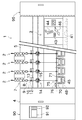
次に、本発明の一実施形態に係る精紡機(紡績機)について、図面を参照して説明する。図1に示す精紡機1は、並設された多数の紡績ユニット2と、糸継台車3と、原動機ボックス4と、ブロアボックス95と、機台制御装置90と、を備えている。
Next, a spinning machine (spinning machine) according to an embodiment of the present invention will be described with reference to the drawings. A
機台制御装置90は、精紡機1が備える各構成を集中的に管理するためのものであって、モニタ91と入力キー92とを備える。オペレータが入力キー92を用いて適宜の操作を行うことにより、特定の紡績ユニット2又は全ての紡績ユニット2の設定及び/又は状態等をモニタ91に表示することができる。
The
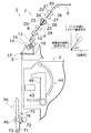
図2に示すように、各紡績ユニット2は、上流から下流へ向かって順に配置された、ドラフト装置7と、空気紡績装置9と、糸貯留装置14と、巻取装置70と、を備えている。なお、本明細書において「上流」及び「下流」とは、紡績時でのスライバ6、繊維束8及び紡績糸10の走行(搬送)方向における上流及び下流を意味する。各紡績ユニット2は、ドラフト装置7から送られてくる繊維束8を空気紡績装置9で紡績して紡績糸10を生成し、この紡績糸10を巻取装置70で巻き取ってパッケージ45を形成する。
As shown in FIG. 2, each
ドラフト装置7は精紡機1の筐体5の上端近傍に設けられている。ドラフト装置7は、図略のスライバケースからスライバガイド20を介して供給されるスライバ(繊維束)6を、所定の太さになるまでドラフト(繊維束を引き伸ばすこと)するものである。ドラフト装置7でドラフトされた繊維束8は、空気紡績装置9に供給される。なお、ドラフト装置7の詳細については後述する。
The
空気紡績装置9は、ドラフト装置7から供給された繊維束8に撚りを加えて、紡績糸10を生成する。本実施形態では、旋回気流を利用して繊維束8に撚りを与える空気式の紡績装置を採用している。具体的には、空気紡績装置9は、詳細な説明や図示は省略するが、繊維案内部と、旋回流発生ノズルと、中空ガイド軸体と、を備えている。繊維案内部は、ドラフト装置7から送られた繊維束8を、空気紡績装置9の内部に形成される紡績室に案内する。旋回流発生ノズルは、繊維束8の経路の周囲に配置され、紡績室内に旋回流を発生させる。この旋回流によって、紡績室内の繊維束8の繊維端が反転され旋回する。中空ガイド軸体は、紡績された紡績糸10を紡績室から空気紡績装置9の外部へと案内する。
The
空気紡績装置9の下流には、糸品質測定器12と、スピニングセンサ13と、が設けられている。空気紡績装置9で紡出された紡績糸10は、糸品質測定器12及びスピニングセンサ13を通過する。
A yarn
糸品質測定器12は、走行する紡績糸10の太さを、図略の光学式センサによって監視する。糸品質測定器12は、紡績糸10の糸欠陥(紡績糸10の太さなどに異常がある箇所)を検出した場合に、糸欠陥検出信号を図略のユニットコントローラへ送信する。糸品質測定器12は光学式のセンサに限らず、例えば静電容量式のセンサで紡績糸10の太さを監視する構成であっても良い。また、糸品質測定器12は、紡績糸10に含まれる異物を糸欠陥として検出しても良い。
The yarn
スピニングセンサ13は、糸品質測定器12のすぐ下流側に配置されている。スピニングセンサ13は、空気紡績装置9と糸貯留装置14との間における紡績糸10のテンションを検出することができる。スピニングセンサ13は、この検出したテンションを前記ユニットコントローラへと送信する。ユニットコントローラは、スピニングセンサ13が検出したテンションを監視することにより、弱糸などの異常箇所を検出する。
The spinning
糸品質測定器12及びスピニングセンサ13の下流には、糸貯留装置14が設けられている。糸貯留装置14は、図2に示すように、糸貯留ローラ15と、当該糸貯留ローラ15を回転駆動するモータ16と、を備えている。
A
糸貯留ローラ15は、その外周面に一定量の紡績糸10を巻き付けて一時的に貯留することができる。糸貯留ローラ15の外周面に紡績糸10を巻き付けた状態で当該糸貯留ローラ15を所定の回転速度で回転させることにより、空気紡績装置9から紡績糸10を所定の速度で引き出して下流側に搬送することができる。また、糸貯留ローラ15の外周面に紡績糸10を一時的に貯留することができるので、糸貯留装置14を一種のバッファとして機能させることができる。これにより、空気紡績装置9における紡績速度と、巻取速度(パッケージ45へ巻き取られる紡績糸10の速度)と、が何らかの理由により一致しない不具合(例えば紡績糸10の弛みなど)を解消することができる。
The
糸貯留装置14の下流には、糸ガイド17及び巻取装置70が配置されている。巻取装置70は、支軸73まわりに揺動可能に支持されたクレードルアーム71を備える。このクレードルアーム71は、紡績糸10を巻回するためのボビン48を回転可能に支持することができる。
A
巻取装置70は、巻取ドラム(接触ローラ)72と、トラバース装置75と、を備えている。また、巻取装置70は、図略の巻取ドラム駆動モータを備えている。巻取ドラム72は、巻取ドラム駆動モータの駆動力が伝達されることにより、前記ボビン48又はパッケージ45の外周面に接触した状態で回転する。トラバース装置75は、紡績糸10に係合可能なトラバースガイド76を備えている。巻取装置70は、トラバースガイド76を図略の駆動手段によって往復動させながら巻取ドラム72を巻取ドラム駆動モータによって駆動する。これにより、巻取装置70は、巻取ドラム72に接触するパッケージ45を回転させ、紡績糸10を綾振りしつつ、紡績糸10をパッケージ45に巻き取る。
The winding
糸継台車3は、図1及び図2に示すように、糸継装置43と、サクションパイプ44及びサクションマウス46を備えている。糸継台車3は、ある紡績ユニット2で糸切れ又は糸切断が発生すると、レール41上を当該紡績ユニット2まで走行し、停止する。前記サクションパイプ44は、軸を中心に上下方向に回動しながら、空気紡績装置9から送出される紡績糸10を吸い込みつつ捕捉して糸継装置43へ案内する。サクションマウス46は、軸を中心に上下方向に回動しながら、パッケージ45から紡績糸10を吸引しつつ捕捉して糸継装置43へ案内する。糸継装置43は、案内された紡績糸10同士の糸継ぎを行う。
As illustrated in FIGS. 1 and 2, the
次に、図2を参照して、ドラフト装置7について詳細に説明する。初めにドラフト装置7が備えるドラフトローラについて説明する。
Next, the
図2に示すように、ドラフト装置7は、繊維束8を導入するための筒状のスライバガイド20を備えるとともに、互いに対向するボトムローラとトップローラから構成されるドラフトローラ対を複数備える。ボトムローラは、精紡機1の背面側(下側)に位置しており、トップローラは、精紡機1の正面側(上側)に位置している。本実施形態のドラフト装置7は、上流側から順に、バックローラ対、サードローラ対、ミドルローラ対、フロントローラ対を備えた、いわゆる4線式のドラフト装置として構成されている。また、本実施形態では、精紡機1の設置面(水平面)と、ドラフト装置7のスライバ搬送方向(糸道)と、がなす角が45°以上90°以下である。
As shown in FIG. 2, the
複数のトップローラは、上流側から順に、バックトップローラ21、サードトップローラ22、エプロンベルト23が設けられたミドルトップローラ24、及びフロントトップローラ25である。複数のボトムローラは、上流側から順に、バックボトムローラ26、サードボトムローラ27、エプロンベルト23が設けられたミドルボトムローラ28、及びフロントボトムローラ29である。
The plurality of top rollers are a back
各トップローラ21,22,25は、その外周面がゴム等の弾性部材から構成されているローラである。各トップローラ21,22,24,25は、図略の軸受等を介して、その軸線を中心に回転可能に支持されている。各ボトムローラ26,27,28,29は金属製のローラであり、その軸線を中心に回転駆動されるように構成されている。
Each of the
ドラフト装置7は、各トップローラ21,22,24,25を、それに対向するボトムローラ26,27,28,29に向かって付勢する付勢手段(図示略)を有している。これにより、トップローラ21,22,24,25の外周面が,ボトムローラ26,27,28,29の外周面にそれぞれ弾性的に接触する。この構成で、ボトムローラ26,27,28,29を回転駆動することにより、これに対向して接触するトップローラ21,22,24,25も従動回転する。
The
ドラフト装置7は、回転するトップローラ21,22,24,25とボトムローラ26,27,28,29の間で繊維束8をニップする(挟み込む)ことにより、当該繊維束8を下流側に向けて搬送する。ドラフト装置7においては、下流側のドラフトローラ対ほど回転速度が速くなるように構成されている。従って、繊維束8は、ドラフトローラ対とドラフトローラ対との間で搬送される間に引き伸ばされ(ドラフトされ)、これに伴い、下流側ほど繊維束8の太さが細くなっていく。
The
各ボトムローラ26,27,28,29の回転速度を適宜設定することにより、繊維束8がドラフトされる程度を変更できる。したがって、所望の太さになるようにドラフトした繊維束8を空気紡績装置9に対して供給することができる。これにより、空気紡績装置9において、所望の番手(太さ)の紡績糸10を紡績することができる。
By appropriately setting the rotation speeds of the
次に、図3から図6までを参照して、ドラフト装置7が備える繊維制御部材50について説明する。なお、図3から図5は、ドラフトローラのうちバックボトムローラ26とサードボトムローラ27の近傍のみを示す図である。
Next, the
図3等に示すように、バックボトムローラ26は、ドラフト部26aと、小径部(縮径部)26bと、から構成されている。ドラフト部26aは、バックボトムローラ26の軸方向の中央部分に位置している。ドラフト部26aの外径は、全体として一定である。バックボトムローラ26のドラフト部26aとバックトップローラ21のドラフト部とでスライバ6を挟み込んで、スライバ6をドラフトする。
As shown in FIG. 3 and the like, the
小径部26bは、ドラフト部26aの両端に接続された部分である。小径部26bは、ドラフト部26aから離れるに従って径が小さくなった後に再び大きくなる部分である。サードボトムローラ27も同様に、ドラフト部27a及び小径部27bから構成されている。図には示していないが、他のボトムローラも同様である。
The
また、図3等に示すように、ドラフト装置7は、ドラフトローラ支持部60を備える。ドラフトローラ支持部60は、所定の間隔を開けて対向するように配置された2つの壁状部材60a及び60bから構成される。壁状部材60a及び60bは、それぞれボトムローラ(詳細には小径部26b,27b)の各端部を保持する。本実施形態ではバックボトムローラ26を保持する壁状部材60aと、サードボトムローラ27を保持する壁状部材60aと、は別体である。同様に、バックボトムローラ26を保持する60bと、サードボトムローラ27を保持する壁状部材60bと、も別体である。なお、2つの壁状部材60aは一体であっても良いし、2つの壁状部材60bは、一体であっても良い。
As shown in FIG. 3 and the like, the
また、壁状部材60a及び60bのうち、バックボトムローラ26を保持する部分の近傍の領域には、それぞれ取付溝61が形成されている。取付溝61は、ボトムローラの配列方向を垂直に横切るように形成されている。なお、取付溝61は、壁状部材60a及び60bとは別に設けられた部材に形成されていても良い。
Further, in the wall-shaped
取付溝61には、繊維制御部材50が取り付けられる。繊維制御部材50は、厚さが例えば1.6mmから2.0mmの板状部材から形成されている。繊維制御部材50は、耐摩耗性を発揮させるために硬質クロム等でメッキされている。
The
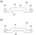
繊維制御部材50には、スライバ湾曲部(繊維束湾曲部)51と、切欠き52と、取付部53と、が形成されている。以下の説明では、図6(a)に示すように、繊維制御部材50がスライバと接触する側(スライバ湾曲部51が形成される側)をスライバ側と称し、その反対側を反スライバ側と称することがある。また、繊維制御部材50のスライバ側の端部を第1端部と称し、繊維制御部材50の反スライバ側の端部を第2端部と称する。
The
スライバ湾曲部51は、繊維制御部材50のスライバ側の端部に形成されている。スライバ湾曲部51は、繊維制御部材50の長手方向(ボトムローラの軸方向)の中央部(端部を避けた位置)に形成されている。スライバ湾曲部51の長手方向の長さは、ドラフト部26a及び27aの長さと略同じである。
The
スライバ湾曲部51は、板状部材をバックボトムローラ26に向けて(スライバ6の搬送方向の上流側)に湾曲させるように複数回折り曲げて形成された部分である。当該折り曲げられた部分の外側表面がスライバ6と接触することにより、スライバ湾曲部51はスライバ6の搬送経路を湾曲させる(図5)。繊維制御部材50を設けることにより、スライバ6の脱落を防止することができる。また、ドラフト比を大きくしても、ドラフト装置7によりスライバ6をドラフトすることができる。なお、スライバ湾曲部51とバックボトムローラ26との隙間L(図5)は、1.2mm以上2.0mm以下であることが好ましい。
The
切欠き52は、図6(a)に示すように、反スライバ側の端部である第2端部に形成され、反スライバ側の端部からスライバ側に向けて(換言すれば第1端部に近づくように)板状部材を切り欠いて形成された部分である。切欠き52は、繊維制御部材50の長手方向の中央部(端部を避けた位置)に形成されている。切欠き52の長手方向の大きさ(幅、長さ)は、スライバ湾曲部51の長手方向の大きさよりも小さい。また、切欠き52における反スライバ側の幅をL1とし、スライバ側の幅をL2としたときに、L1の方がL2よりも大きい。換言すると、第2端部から第1端部へ向かうに従って(反スライバ側からスライバ側に向かうに従って)、切欠き52の幅が小さくなる。なお、本実施形態では、切欠き52の幅の変化率は略一定である。
As shown in FIG. 6A, the
本実施形態のようにスライバ搬送方向が45°以上90°以下である場合、図5に示すように、ドラフト時において発生した風綿は、重力の影響で落下しにくく繊維制御部材50(特に、スライバ湾曲部51の湾曲部分の内側近傍)に堆積し易い。本実施形態の繊維制御部材50には、切欠き52が形成されているので、風綿を落下させることができ、風綿が堆積しにくい。従って、スライバ搬送方向を大きくしたメリット(ドラフト速度の向上)を享受しつつ、デメリット(風綿の堆積し易さ)を解消できる。
When the sliver conveyance direction is 45 ° or more and 90 ° or less as in the present embodiment, as shown in FIG. 5, the fluff generated at the time of drafting is difficult to fall under the influence of gravity, and the fiber control member 50 (particularly, It is easy to deposit in the vicinity of the curved portion of the sliver curved
取付部53は、繊維制御部材50の長手方向の両端部に形成されている。取付部53の第1端部(スライバ側の端部)は、スライバ湾曲部51の第1端部より第2端部に近い側(反スライバ側)に位置している。これにより、取付部53の周囲(特に繊維制御部材50と取付部53の間の凹部)から、堆積した風綿を落下させることができる。
The
取付部53の第1端部は、スライバ湾曲部51と取付部53の間の第1端部より、スライバ側に位置している。取付部53には、厚さ方向に僅かに突出する半球状の突起が形成されている。
The first end portion of the
図3に示すように、取付部53が取付溝61に挿入されることで、繊維制御部材50がドラフト装置7に取り付けられる。取付溝61の幅は、取付部53の厚みと同程度である、取付部53を取付溝61に挿入するだけで、ドラフトローラ支持部60は取付部53を保持することができる。上記の半球状の突起は、取付溝61の幅と取付部53の厚みとを調整するために形成されたものであり、形成されていなくても良い。また、半球状の突起は、図示されている方向とは反体方向に形成されていても良い。
As shown in FIG. 3, the
取付部53を取り外す場合も、オペレータが取付部53を把持して上側に引き上げるだけで良い。このようにワンタッチで繊維制御部材50を着脱可能とすることで、仮に繊維制御部材50に風綿が堆積した場合であっても、風綿を簡単に除去することができる。
Even when the
次に、図7を参照して、上記実施形態の変形例を説明する。なお、本変形例の説明においては、前述の実施形態と同一又は類似の部材には図面に同一の符号を付し、説明を省略する場合がある。 Next, a modification of the above embodiment will be described with reference to FIG. In the description of this modification, the same or similar members as those in the above-described embodiment may be denoted by the same reference numerals in the drawings, and description thereof may be omitted.
上述した切欠き52の形状は一例であり、適宜変更することができる。例えば図7(a)に示すように、切欠き52の幅が一定であっても良い。この場合、切欠き52を容易に形成することができる。
The shape of the
また、図7(b)に示すように、切欠き52の一部が弧状に形成されていても良い。この場合、切欠き52での風綿の引っ掛かりを防止して、風綿の堆積をより確実に防止することができる。
Moreover, as shown in FIG.7 (b), a part of
以上に説明したように、本実施形態の繊維制御部材50の端部には、ドラフトローラ対がドラフトするスライバ6の搬送経路を曲げるスライバ湾曲部51が形成されている。スライバ湾曲部51が形成されている部分(スライバ湾曲部51が形成されている側の端部)を第1端部と称し、当該スライバ湾曲部51の反対に位置する部分(端部)を第2端部と称する。繊維制御部材50の第2端部には、第1端部に向かって切り欠かれた切欠き52が形成されている。
As described above, the
これにより、ドラフト時に発生した風綿が切欠き52から落下するため、繊維制御部材50及びドラフトローラの周囲に風綿が堆積することを防止できる。従って、風綿の堆積に伴い発生し得る糸切れの発生を抑えることができる。
Thereby, since the fluff generated at the time of the draft falls from the
本実施形態の繊維制御部材50の切欠き52は、第1端部に近づくに従って幅が小さくなる。
The width of the
これにより、風綿が切欠き52に引っ掛かりにくいので、風綿の堆積をより確実に防止することができる。
Thereby, since fluff is hard to be caught in the
本実施形態のドラフト装置7には、繊維制御部材50を挟み込むことで当該繊維制御部材50を保持する取付溝61が形成されている。
In the
これにより、繊維制御部材50を取付溝61に挿入するだけで繊維制御部材50が保持されるので、繊維制御部材50を容易に着脱することができる。従って、仮に風綿が堆積した場合であっても、風綿の除去を素早く行うことができる。
Thereby, since the
本実施形態の繊維制御部材50の幅は、ドラフトローラ(具体的にはバックボトムローラ26とサードボトムローラ27)のドラフト部26aと27aの幅と略同一である。繊維制御部材50の端部のうち、ドラフトローラの小径部26bと27bにそれぞれ対向する部分は、ドラフト部26aと27aにそれぞれ対応する部分よりも、スライバ6から離れる側に形成されている。
The width of the
ドラフト装置7は、ボトムローラ26,27の中央部のドラフト部26a,27aでスライバ6をドラフトする。したがって、繊維制御部材50の端部のうち、ボトムローラ26、27の小径部26b,27bに対向する端部の位置をスライバ6から離すことで、ボトムローラ26,27の長手方向の端部近傍における風綿の堆積を抑えることができる。
The
以上に本発明の好適な実施の形態を説明したが、上記の構成は例えば以下のように変更することができる。 The preferred embodiment of the present invention has been described above, but the above configuration can be modified as follows, for example.
上記実施形態では、バックボトムローラ26とサードボトムローラ27の間に繊維制御部材50を配置した。しかし、サードボトムローラ27とミドルボトムローラ28の間に配置されていても良い。
In the above embodiment, the
上記で示したドラフト装置7のトップローラ及びボトムローラの配置は一例である。トップローラとボトムローラの位置関係、又は、ドラフトローラ対の数等を適宜変更しても良い。
The arrangement of the top roller and the bottom roller of the
繊維制御部材50の形状は任意であり、適宜変更することができる。例えば、スライバ湾曲部51は板状部材を湾曲させて形成された形状に限られない。また、切欠き52の形状及び切欠き52を形成する範囲は任意であり、上記実施形態及び変形例で示した形状以外であっても良い。
The shape of the
繊維制御部材50の取付方法は、挿入するだけのワンタッチ方式に限られず、ボルト等で固定する構成であっても良い。
The attachment method of the
1 精紡機(紡績機)
6 スライバ(繊維束)
7 ドラフト装置
26 バックボトムローラ(ドラフトローラ)
27 サードボトムローラ(ドラフトローラ)
50 繊維制御部材
51 スライバ湾曲部(繊維束湾曲部)
52 切欠き
53 取付部
60 ドラフトローラ支持部
61 取付溝
70 巻取装置
1 Spinning machine (spinning machine)
6 Sliver (fiber bundle)
7
27 Third bottom roller (draft roller)
50
52
Claims (10)
前記繊維束湾曲部が形成されている部分を第1端部と称し、当該繊維束湾曲部の反対に位置する部分を第2端部と称したときに、前記第2端部には、前記第1端部に向かって切り欠かれた切欠きが形成されていることを特徴とする繊維制御部材。 In the fiber control member in which the fiber bundle bending portion that bends the conveyance path of the fiber bundle that the draft roller pair drafts is formed at the end,
When the portion where the fiber bundle bending portion is formed is referred to as a first end portion, and when the portion located opposite to the fiber bundle bending portion is referred to as a second end portion, the second end portion includes the A fiber control member, wherein a notch cut out toward the first end is formed.
前記切欠きは、前記第1端部に近づくに従って、当該切欠きの幅が小さくなることを特徴とする繊維制御部材。 The fiber control member according to claim 1,
The fiber control member according to claim 1, wherein the width of the notch is reduced as the notch approaches the first end.
長手方向の端部における前記第1端部の位置は、前記繊維束湾曲部における前記第1端部の位置よりも、前記第2端部に近いことを特徴とする繊維制御部材。 The fiber control member according to claim 1 or 2,
The fiber control member characterized in that the position of the first end portion at the end portion in the longitudinal direction is closer to the second end portion than the position of the first end portion in the fiber bundle bending portion.
板状部材で構成されており、板厚が1.6mm以上2.0mm以下であることを特徴とする繊維制御部材。 The fiber control member according to any one of claims 1 to 3,
A fiber control member comprising a plate-like member and having a plate thickness of 1.6 mm or more and 2.0 mm or less.
繊維束をドラフトするドラフトローラと、
を備え、
前記繊維制御部材を挟み込むことで当該繊維制御部材を保持する取付溝が形成されていることを特徴とするドラフト装置。 The fiber control member according to any one of claims 1 to 4,
A draft roller for drafting fiber bundles;
With
A draft device characterized in that an attachment groove for holding the fiber control member is formed by sandwiching the fiber control member.
前記ドラフトローラを支持するドラフトローラ支持部を備え、
前記取付溝が前記ドラフトローラ支持部に形成されていることを特徴とするドラフト装置。 The draft device according to claim 5, wherein
A draft roller support portion for supporting the draft roller;
The draft device, wherein the mounting groove is formed in the draft roller support portion.
前記ドラフトローラは、軸方向の中央部のドラフト部と、前記軸方向において前記ドラフト部の両側に位置する小径部と、を有し、
前記繊維束湾曲部の幅は、前記ドラフト部の幅と略同一であり、
前記繊維制御部材の長手方向の端部は、前記小径部に対向するように配置されており、前記繊維束湾曲部よりも、前記第2端部に近いことを特徴とするドラフト装置。 The draft device according to claim 5 or 6,
The draft roller has a draft portion at a central portion in the axial direction, and small diameter portions located on both sides of the draft portion in the axial direction,
The width of the fiber bundle bending portion is substantially the same as the width of the draft portion,
The draft device characterized in that an end portion in the longitudinal direction of the fiber control member is disposed so as to face the small diameter portion, and is closer to the second end portion than the fiber bundle bending portion.
複数のドラフトローラ対を備え、
前記複数のドラフトローラ対のそれぞれは、トップローラ及びボトムローラから構成され、
前記繊維制御部材は、ドラフト方向の上流側から1番目に配置される前記ボトムローラと、上流側から2番目に配置される前記ボトムローラと、の間に配置されていることを特徴とするドラフト装置。 A draft device according to any one of claims 5 to 7,
With multiple draft roller pairs,
Each of the plurality of draft roller pairs is composed of a top roller and a bottom roller,
The fiber control member is disposed between the bottom roller disposed first from the upstream side in the draft direction and the bottom roller disposed second from the upstream side. apparatus.
前記ドラフト装置でドラフトされた繊維束を空気流で撚って紡績糸を生成する空気紡績装置と、
前記空気紡績装置から供給される紡績糸をパッケージに巻き取る巻取装置と、
を備えることを特徴とする紡績機。 A draft device according to any one of claims 5 to 8;
An air spinning device for producing a spun yarn by twisting a fiber bundle drafted by the draft device with an air flow;
A winding device for winding the spun yarn supplied from the pneumatic spinning device into a package;
A spinning machine characterized by comprising:
設置面と、前記ドラフト装置の繊維束搬送方向と、がなす角が45°以上90°以下であることを特徴とする紡績機。 The spinning machine according to claim 9, wherein
The spinning machine is characterized in that an angle formed by the installation surface and the fiber bundle conveying direction of the draft device is 45 ° or more and 90 ° or less.
Priority Applications (3)
| Application Number | Priority Date | Filing Date | Title |
|---|---|---|---|
| JP2014056396A JP2015178688A (en) | 2014-03-19 | 2014-03-19 | Fiber control member, draft apparatus and spinner |
| CN201510113951.4A CN104928814B (en) | 2014-03-19 | 2015-03-16 | Fibre controlling part part, drafting system and spinning machinery |
| EP15159590.7A EP2921577B1 (en) | 2014-03-19 | 2015-03-18 | Draft device and spinning machine |
Applications Claiming Priority (1)
| Application Number | Priority Date | Filing Date | Title |
|---|---|---|---|
| JP2014056396A JP2015178688A (en) | 2014-03-19 | 2014-03-19 | Fiber control member, draft apparatus and spinner |
Publications (1)
| Publication Number | Publication Date |
|---|---|
| JP2015178688A true JP2015178688A (en) | 2015-10-08 |
Family
ID=52784918
Family Applications (1)
| Application Number | Title | Priority Date | Filing Date |
|---|---|---|---|
| JP2014056396A Pending JP2015178688A (en) | 2014-03-19 | 2014-03-19 | Fiber control member, draft apparatus and spinner |
Country Status (3)
| Country | Link |
|---|---|
| EP (1) | EP2921577B1 (en) |
| JP (1) | JP2015178688A (en) |
| CN (1) | CN104928814B (en) |
Families Citing this family (3)
| Publication number | Priority date | Publication date | Assignee | Title |
|---|---|---|---|---|
| JP2018204121A (en) * | 2017-05-30 | 2018-12-27 | 村田機械株式会社 | Roller unit, draft machine and spinning machine |
| IT201800010209A1 (en) * | 2018-11-09 | 2020-05-09 | Savio Macch Tessili Spa | IRONING APPARATUS AND METHOD FOR AIR SPINNING MACHINES WITH MULTIPLE POWER SUPPLIES |
| DE102019115905A1 (en) * | 2019-06-12 | 2020-12-17 | Saurer Intelligent Technology AG | Drafting unit with a load carrier and load carrier for a drafting unit |
Family Cites Families (10)
| Publication number | Priority date | Publication date | Assignee | Title |
|---|---|---|---|---|
| GB182507A (en) * | 1921-02-05 | 1922-07-05 | Arthur Cecil Butler | Improvements in mechanism for drawing or drafting cotton, cotton waste wool and other fibrous materials |
| US1990613A (en) * | 1934-06-11 | 1935-02-12 | Piron Fernand | Spinning machine |
| US2450251A (en) * | 1945-04-13 | 1948-09-28 | Casablancas High Draft Co Ltd | Collector for textile drafting mechanisms |
| JPS4420501Y1 (en) * | 1967-04-12 | 1969-09-02 | ||
| JPH1025628A (en) * | 1996-07-09 | 1998-01-27 | Howa Mach Ltd | Pressure bar for spinning machinery |
| EP1526194A3 (en) * | 2003-10-21 | 2006-06-21 | Maschinenfabrik Rieter Ag | Spinning machine comprising a condensing device |
| JP2006200069A (en) | 2005-01-20 | 2006-08-03 | Murata Mach Ltd | Draft mechanism in air-jet fine spinning frame |
| DE102006041770A1 (en) * | 2006-09-04 | 2008-03-06 | Maschinenfabrik Rieter Ag | Fiber compression device for drawing system of spinning machine equipped with roller pairs, comprises a holding device having guiding arms, a compressor element, compressor body, holding arms with mounting units, and further mounting units |
| CN201010722Y (en) * | 2006-12-18 | 2008-01-23 | 上海二纺机股份有限公司 | Compact spinning apparatus of ring spinning frame |
| CN101550620B (en) * | 2009-05-14 | 2011-03-30 | 童云章 | Special-purpose collecting component for cotton type siro spinning |
-
2014
- 2014-03-19 JP JP2014056396A patent/JP2015178688A/en active Pending
-
2015
- 2015-03-16 CN CN201510113951.4A patent/CN104928814B/en active Active
- 2015-03-18 EP EP15159590.7A patent/EP2921577B1/en active Active
Also Published As
| Publication number | Publication date |
|---|---|
| CN104928814A (en) | 2015-09-23 |
| EP2921577A2 (en) | 2015-09-23 |
| EP2921577A3 (en) | 2016-05-04 |
| EP2921577B1 (en) | 2019-08-28 |
| CN104928814B (en) | 2019-10-18 |
Similar Documents
| Publication | Publication Date | Title |
|---|---|---|
| EP2565307A2 (en) | Spinning machine | |
| EP2876193B1 (en) | Cleaning device, drafting device, and spinning unit | |
| JP2015178688A (en) | Fiber control member, draft apparatus and spinner | |
| JP2012107363A (en) | Draft roller, draft machine and spinning machine | |
| JP2016194173A (en) | Draft device and spinning machine | |
| EP2366817B1 (en) | Spinning machine | |
| JP2015178687A (en) | Belt guide roller, cleaning device, draft machine and spinning machine | |
| JP2014125714A (en) | Spinning machine | |
| EP3026152B1 (en) | Fiber collecting device, drafting device, and spinning machine | |
| CN214458527U (en) | Drafting device, spinning machine and drafting roller | |
| JP2012057273A (en) | Spinning machine | |
| CN104562318B (en) | Drafting system and weaving loom | |
| EP2573230B1 (en) | Draft device and spinning machine | |
| CN108977945B (en) | Roller unit, draft device, and spinning machine | |
| EP3153613A1 (en) | Drafting device, spinning machine, and method of spinning technical field | |
| EP2573221B1 (en) | Spinning machine | |
| CN206396379U (en) | Drawing rollers supporting mass, drawing rollers, drafting system and spinning machinery | |
| JP2022027203A (en) | Draft machine and spinning unit | |
| EP2752512A1 (en) | Spinning machine | |
| JP2022020895A (en) | Air spinning device, air spinning machine and spinning method | |
| EP2573229B1 (en) | Draft device and spinning machine | |
| JP2013253359A (en) | Spinning machine | |
| JP2024036746A (en) | Fiber guide, air spinning device, and air spinning machine | |
| JP2015067440A (en) | Textile machine | |
| JP2019052387A (en) | Spinning machine |