EP2572946B1 - Locking safety for an electric steering lock - Google Patents
Locking safety for an electric steering lock Download PDFInfo
- Publication number
- EP2572946B1 EP2572946B1 EP12006624.6A EP12006624A EP2572946B1 EP 2572946 B1 EP2572946 B1 EP 2572946B1 EP 12006624 A EP12006624 A EP 12006624A EP 2572946 B1 EP2572946 B1 EP 2572946B1
- Authority
- EP
- European Patent Office
- Prior art keywords
- steering lock
- electric steering
- locking
- lock according
- driving wheel
- Prior art date
- Legal status (The legal status is an assumption and is not a legal conclusion. Google has not performed a legal analysis and makes no representation as to the accuracy of the status listed.)
- Not-in-force
Links
Images

Classifications
-
- B—PERFORMING OPERATIONS; TRANSPORTING
- B60—VEHICLES IN GENERAL
- B60R—VEHICLES, VEHICLE FITTINGS, OR VEHICLE PARTS, NOT OTHERWISE PROVIDED FOR
- B60R16/00—Electric or fluid circuits specially adapted for vehicles and not otherwise provided for; Arrangement of elements of electric or fluid circuits specially adapted for vehicles and not otherwise provided for
-
- B—PERFORMING OPERATIONS; TRANSPORTING
- B60—VEHICLES IN GENERAL
- B60R—VEHICLES, VEHICLE FITTINGS, OR VEHICLE PARTS, NOT OTHERWISE PROVIDED FOR
- B60R25/00—Fittings or systems for preventing or indicating unauthorised use or theft of vehicles
- B60R25/01—Fittings or systems for preventing or indicating unauthorised use or theft of vehicles operating on vehicle systems or fittings, e.g. on doors, seats or windscreens
- B60R25/02—Fittings or systems for preventing or indicating unauthorised use or theft of vehicles operating on vehicle systems or fittings, e.g. on doors, seats or windscreens operating on the steering mechanism
- B60R25/021—Fittings or systems for preventing or indicating unauthorised use or theft of vehicles operating on vehicle systems or fittings, e.g. on doors, seats or windscreens operating on the steering mechanism restraining movement of the steering column or steering wheel hub, e.g. restraining means controlled by ignition switch
- B60R25/0215—Fittings or systems for preventing or indicating unauthorised use or theft of vehicles operating on vehicle systems or fittings, e.g. on doors, seats or windscreens operating on the steering mechanism restraining movement of the steering column or steering wheel hub, e.g. restraining means controlled by ignition switch using electric means, e.g. electric motors or solenoids
- B60R25/02153—Fittings or systems for preventing or indicating unauthorised use or theft of vehicles operating on vehicle systems or fittings, e.g. on doors, seats or windscreens operating on the steering mechanism restraining movement of the steering column or steering wheel hub, e.g. restraining means controlled by ignition switch using electric means, e.g. electric motors or solenoids comprising a locking member radially and linearly moved towards the steering column
Definitions
- the invention relates to a locking protection for an electric steering lock for a vehicle with an electrically driven drive wheel and a locking pin.
- the locking pin is secured by a locking surface of the drive wheel in an unlocked state of the steering lock.
- the DE 103 56 660 discloses a cam which positively forcibly controls a locking member both during locking and unlocking.
- the locking member has the cam towards an open corresponding mating contour.
- grooves are formed with respect to the cross-sectional area congruent to the Sperranthesis.
- the cam disk is formed as a bead cam disk (outer lifting cam) in which an axially projecting bead positively engages between two projections formed on the locking member and in turn positively positively controls both locking and unlocking.
- a blocking element is axially formed by the drive wheel.
- the invention is therefore based on the object to provide a locking protection for an electric steering lock for a vehicle, which avoids the disadvantages of the prior art, which is inexpensive to manufacture, has a compact design, cost, fast and reliable error prevention mount and can be used for a wide variety of vehicle types due to a different kinematics.
- FIGS. 1 and 2 schematically show an electric steering lock 1 for a vehicle with an electrically driven drive wheel 2 and a locking pin.
- the rotation axis R of the drive wheel 2 is oriented perpendicular to an extension direction of the lock pin 3.
- a lifting movement H of the locking pin 3 is thus perpendicular to the axis of rotation R of the drive wheel 2.
- a first portion of the drive wheel 2 is a substantially axially extending locking surface 2c, as a ring segment-shaped projecting portion formed.
- This blocking surface 2c is preferably integrally formed on the drive wheel 2 in this embodiment and extends over an arc angle of 60 °.
- the wall thickness in this case essentially corresponds to an interference counterpart to be secured.
- a cam 2a for driving a control pin 4 is integrally formed on an outer surface of the drive wheel 2.
- the control pin 4 is non-positively connected to the locking pin 3 and transmits the lifting movement of the cam 2a to the locking pin 3.
- a toothing 2b is formed radially.
- This toothing 2 b is also formed integrally with the drive wheel 2.
- Adjacent to the central portion 2 pulse generators are arranged in an upper portion of the drive wheel and designed to detect the rotation angle or the current position of the drive wheel 2 and thus also the current position of the lift curve. As a result, a statement about the locking or unlocking state can be clearly made.
- the locking pin 3 is guided in a locking pin bearing, not shown here, substantially free of play and translationally along its vertical axis.
- the locking pin 3 is substantially an elongated, rectangular cross-section with corresponding longitudinal and transverse axis.
- the faces are essentially curved slightly outward, ie convex.
- the two side surfaces are flat.
- a freewheel groove 3a is formed in an upper portion, on one of the curved surfaces.
- the length or height of the freewheel groove 3a corresponds to the stroke of the cam 2a of the drive wheel 2 and allows a translational movement of the locking pin 3, when the locking surface 2c of the drive wheel 2 is pivoted in the direction of the locking pin 3 during a locking or unlocking and the Freewheel groove 3a passes through.
- the locking pin 3 has a securing groove 3b.
- the locking pin 3 In an unlocked position of the steering lock 3 is the locking pin 3 via the locking groove 3b in engagement with the locking surface 2c of the drive wheel 2. Due to the rotational movement of the drive wheel 2, the locking protection 2c is brought by pivoting the locking surface 2c into engagement with the securing groove 3b.
- the length or height of the securing groove 3b corresponds to the wall thickness of the securing surface 2c plus a game.
- a substantially wedge or runner-shaped portion At a lower portion of the locking pin 3 there is a substantially wedge or runner-shaped portion. This section is for locking in engagement with a steering column. This wedge-shaped portion is aligned to a (not shown) steering column axis in order to effect an optimal locking engagement in a mounted on the steering column Nutenkranz.
- a sintered steel such as D32.
- control pin 4 In the assembled state, the control pin 4 is in engagement with the drive wheel 2 through the cam 2a.
- the control pin 4 is frictionally connected to the locking pin 3 in a central portion and converts the Rotary movement of the drive wheel 2 by means of the cam 2a and the control pin in a translational movement of the locking pin 3 to.
- a toothing 2b' is formed radially. As a result, a toothed engagement with a helical gear is possible.
- This toothing 2b ' is also formed integrally with the drive wheel 2'.
- the diameter of the toothing 2b ' is less than the diameter of the blocking surface 2c', so that the blocking surface 2c 'is radially projecting relative to the toothing 2b' is executed.
- This lift curve 2a ' in turn extends to the outer surface of the drive wheel 2' and is thus integrally formed. Furthermore, in this upper section, pulse generators are arranged and designed to detect the angle of rotation or the current position of the drive wheel 2 'and thus also the current position of the lift curve 2a'. As a result, a statement about the locking or unlocking status can be clearly made.
- the locking pin 3 ' in the upper portion of two non-illustrated non-uniform grooves on two opposite, planar side surfaces. On one of the two curved to the drive wheel 2 'facing surfaces a groove connecting the two grooves is still formed. These three grooves allow a fail-safe assembly of an actuator 4 ', since all three grooves differ. About this actuator 4 ', the locking pin 3' by the lifting cam 2a 'of the drive wheel 2' translationally moved. Due to the rotational movement of the drive wheel 2 ', the locking guard 2c' is also brought into engagement with the securing groove 3b 'by swinging in the locking surface 2c'.
- a locking pin 3, 3 ' is formed as a rotating part of C45.
- a locking pin 3 for a locking pin 3, 3 'both other geometric shapes such as, cubes, cylinders, etc., as well as other materials such as aluminum, fiber reinforced plastics, etc., conceivable. Also, an integral design of a control pin or actuator 4, 4 'with the locking pin 3; 3 'is conceivable.
- a drive wheel 2, 2 'made of a fiber-reinforced plastic by injection molding but other materials such as aluminum, steel grades, C45, etc., are conceivable.
Landscapes
- Engineering & Computer Science (AREA)
- Mechanical Engineering (AREA)
- Lock And Its Accessories (AREA)
Description
Die Erfindung betrifft einen Verriegelungsschutz für eine elektrische Lenkverriegelung für ein Fahrzeug mit einem elektrisch angetriebenen Antriebsrad und einem Sperrbolzen. Dabei wird der Sperrbolzen durch eine Sperrfläche des Antriebsrads in einem unverriegelten Zustand der Lenkverriegelung gesichert.The invention relates to a locking protection for an electric steering lock for a vehicle with an electrically driven drive wheel and a locking pin. In this case, the locking pin is secured by a locking surface of the drive wheel in an unlocked state of the steering lock.
Aus dem bekannten Stand der Technik sind eine Vielzahl von Lenkverriegelungen bekannt, die jedoch in der Regel keinen Verriegelungsschutz zur Vermeidung einer unfreiwilligen Sperrung einer Lenkspindel, z.B. während der Fahrt, aufweisen.From the known prior art, a plurality of steering locks are known which, however, usually do not provide locking protection to prevent involuntary locking of a steering shaft, e.g. while driving, exhibit.
Die
- ein Sperrelement, eine spiralförmig ausgebildete Hubkurve zum Entriegeln des Sperrbolzens und ein Sicherungselement, das an dem Sperrbolzen angeordnet ist, wobei der Sperrbolzen zwischen einer Sperrstellung und einer Freigabestellung bewegbar ist und wobei das Sperrelement an dem Antriebsrad als radial vom Antriebsrad hervorstehende Sperrfläche ausgebildet ist und in der Freigabestellung mit dem an dem Sperrbolzen angeordneten Sicherungselement in Eingriff steht, um ein unbeabsichtigtes Verriegeln der Lenkverriegelung zu verhindern, wobei das Sperrelement zwischen einer Sperrstellung und einer Freigabestellung beweglich ist und die Hubkurve an dem Antriebsrad angeordnet ist.
- a locking element, a helically shaped lifting cam for unlocking the locking pin and a securing element which is arranged on the locking pin, wherein the locking pin between a locking position and a release position is movable and wherein the blocking element is formed on the drive wheel as radially protruding from the drive locking surface and in the release position is engaged with the locking element disposed on the locking pin to prevent inadvertent locking of the steering lock, wherein the locking element between a locking position and a release position is movable and the lifting cam is arranged on the drive wheel.
Der Erfindung liegt daher die Aufgabe zugrunde, einen Verriegelungsschutz für eine elektrische Lenkverriegelung für ein Fahrzeug zur Verfügung zu stellen, welche die Nachteile des Standes der Technik vermeidet, die kostengünstig zu fertigen ist, eine kompakte Bauform aufweist, kostengünstig, schnell und bei sicherer Fehlervermeidung zu montieren und für unterschiedlichste Fahrzeugtypen aufgrund einer unterschiedlichen Kinematik verwendbar ist.The invention is therefore based on the object to provide a locking protection for an electric steering lock for a vehicle, which avoids the disadvantages of the prior art, which is inexpensive to manufacture, has a compact design, cost, fast and reliable error prevention mount and can be used for a wide variety of vehicle types due to a different kinematics.
Diese Aufgabe wird durch eine elektrische Lenkverriegelung für ein Fahrzeug mit den Merkmalen des Anspruchs 1 gelöst. Vorteilhafte Ausführungsformen und Weiterbildungen der Erfindung werden in den Unteransprüchen beschrieben.This object is achieved by an electric steering lock for a vehicle having the features of
Nachfolgend wird die Erfindung anhand eines Ausführungsbeispiels zusammen mit den beigefügten Zeichnungen erläutert. Dazu zeigt:
-
Figur 1 -
Figur 2Figur 1 -
Figur 3 -
Figur 4Figur 3 -
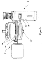
Figur 5 eine räumliche Darstellung des Verriegelungsschutzes einer elektrischen Lenkverriegelung gemäß der zweiten Ausführungsform.
-
FIG. 1 a schematic representation of a locking protection of an unclaimed electric steering lock, wherein the locking surface is not engaged with the locking groove; -
FIG. 2 a schematic representation of the locking protection afterFIG. 1 wherein the blocking surface is engaged with the locking groove; -
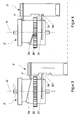
FIG. 3 1 is a schematic representation of a locking protection of an electric steering lock according to an embodiment of the present invention, wherein the locking surface is not engaged with the locking groove, -
FIG. 4 a schematic representation of a locking protection afterFIG. 3 wherein the blocking surface is engaged with the locking groove; and -
FIG. 5 a spatial representation of the locking protection of an electric steering lock according to the second embodiment.
Nachfolgend beziehen sich Richtungsangaben auf die Zeichnungsebene sofern sich aus dem Text nichts anderes ergibt.In the following, directional data refer to the drawing plane unless otherwise stated in the text.
Die
In der nicht beansprüchten Verriegelung ist die Drehachse R des Antriebsrads 2 senkrecht zu einer Erstreckungsrichtung des Sperrbolzens 3 ausgerichtet. Eine Hubbewegung H des Sperrbolzens 3 erfolgt somit senkrecht zur Drehachse R des Antriebsrads 2. In einem ersten Abschnitt des Antriebsrads 2 ist eine sich im Wesentlichen axial erstreckende Sperrfläche 2c, als ringsegmentförmiger, hervorstehender Abschnitt, ausgebildet. Diese Sperrfläche 2c ist in dieser Ausführungsform vorzugsweise integral am Antriebsrad 2 ausgebildet und erstreckt sich über einen Bogenwinkel von 60°. Die Wandstärke entspricht hierbei im Wesentlichen einem zu sichernden Eingriffsgegenstück. Des Weiteren ist in diesem ersten Abschnitt auf einer Außenfläche des Antriebsrads 2 eine Nocke 2a zur Ansteuerung eines Steuerbolzens 4 integral ausgebildet. Der Steuerbolzen 4 ist mit dem Sperrbolzen 3 kraftschlüssig verbunden und überträgt die Hubbewegung der Nocke 2a an den Sperrbolzen 3. In einem mittleren Abschnitt auf der Außenfläche des Antriebsrads 2 ist eine Verzahnung 2b radial ausgebildet. Dadurch ist ein verzahnender Eingriff mit einem schraubenförmig ausgebildeten Getrieberad möglich. Diese Verzahnung 2b ist ebenfalls integral mit dem Antriebsrad 2 ausgebildet. Angrenzend an den mittleren Abschnitt sind in einem oberen Abschnitt des Antriebsrads 2 Impulsgeber angeordnet und ausgebildet, um den Drehwinkel bzw. die aktuelle Stellung des Antriebsrads 2 und somit auch die aktuelle Stellung der Hubkurve zu erfassen. Dadurch kann eindeutig eine Aussage über den Ver- bzw. Entriegelungszustand getroffen werden.In the unclaimed lock, the rotation axis R of the
Der Sperrbolzen 3 wird in einer hier nicht dargestellten Sperrbolzenlagerung im Wesentlichen spielfrei und translatorisch entlang seiner Hochachse geführt. Dabei weist der Sperrbolzen 3 im Wesentlichen einen länglichen, rechteckförmigen Querschnitt mit entsprechender Längs- und Querachse auf. Die Stirnseiten sind dabei im Wesentlichen leicht nach außen gewölbt, d.h. konvex ausgebildet. Die beiden Seitenflächen sind plan ausgebildet. In einem oberen Abschnitt, auf einer der gewölbten Flächen, ist eine Freilaufnut 3a ausgebildet. Dabei entspricht die Länge bzw. Höhe der Freilaufnut 3a dem Hub der Nocke 2a des Antriebsrads 2 und ermöglicht eine translatorische Bewegung des Sperrbolzens 3, wenn die Sperrfläche 2c des Antriebsrads 2 in Richtung des Sperrbolzens 3 während eines Ver- bzw. Entriegelungsvorgangs geschwenkt wird und die Freilaufnut 3a durchquert. Unterhalb dieser Freilaufnut 3a weist der Sperrbolzen 3 eine Sicherungsnut 3b auf. In einer entriegelten Position der Lenkverriegelung 3 befindet sich der Sperrbolzen 3 über die Sicherungsnut 3b in Eingriff mit der Sperrfläche 2c des Antriebsrads 2. Aufgrund der Drehbewegung des Antriebsrads 2 wird der Verriegelungsschutz 2c durch ein Einschwenken der Sperrfläche 2c in Eingriff mit der Sicherungsnut 3b gebracht. Im Wesentlichen entspricht die Länge bzw. Höhe der Sicherungsnut 3b der Wandstärke der Sicherungsfläche 2c zuzüglich eines Spiels. Durch den Eingriff der Sperrfläche 2c in die Sicherungsnut 3b wird eine mechanische Verriegelung zwischen dem Sperrbolzen 3 und dem Antriebsrad 2 bewirkt und somit eine Fehlfunktion der elektrischen Lenkverriegelung, beispielsweise ein plötzliches Verriegeln während der Fahrt, verhindert. An einem unteren Abschnitt des Sperrbolzens 3 befindet sich ein im Wesentlichen keil- bzw. kufenförmiger Abschnitt. Dieser Abschnitt befindet sich zur Verriegelung im Eingriff mit einer Lenksäule. Dieser keilförmige Abschnitt ist dabei zu einer (nicht gezeigten) Lenksäulenachse ausgerichtet, um einen optimalen verriegelnden Eingriff in einen an der Lenksäule angebrachten Nutenkranz bewirken zu können. Zur Verbesserung der Maßhaltigkeit der angewandten Geometrien bei gleichzeitiger Massenproduktion wird der Sperrbolzen 3 im vorliegenden Ausführungsbeispiel im Sinterverfahren aus einem Sinterstahl wie D32 gefertigt.The
In montiertem Zustand befindet sich der Steuerbolzen 4 im Eingriff mit dem Antriebsrad 2 durch die Nocke 2a. Der Steuerbolzen 4 ist mit dem Sperrbolzen 3 in einem mittleren Abschnitt kraftschlüssig verbunden und wandelt die Drehbewegung des Antriebsrads 2 mittels der Nocke 2a und dem Steuerbolzen in eine translatorische Bewegung des Sperrbolzens 3 um.In the assembled state, the
In der Ausführungsform der
Im Gegensatz zur ersten Figur weist der Sperrbolzen 3' in dem oberen Abschnitt zwei nicht dargestellte uneinheitliche Nuten auf zwei gegenüberliegenden, planen Seitenflächen auf. Auf einer der beiden gewölbten zum Antriebsrad 2' weisenden Flächen ist noch eine die beiden Nuten verbindende Quernut ausgebildet. Diese drei Nuten ermöglichen eine verwechslungssichere bzw. fail safe Montage eines Betätigers 4', da sich alle drei Nuten unterscheiden. Über diesen Betätiger 4' wird der Sperrbolzen 3' durch die Hubkurve 2a' des Antriebsrads 2' translatorisch bewegt. Aufgrund der Drehbewegung des Antriebsrads 2' wird der Verriegelungsschutz 2c' ebenfalls durch ein Einschwenken der Sperrfläche 2c' in Eingriff mit der Sicherungsnut 3b' gebracht.In contrast to the first figure, the locking pin 3 'in the upper portion of two non-illustrated non-uniform grooves on two opposite, planar side surfaces. On one of the two curved to the drive wheel 2 'facing surfaces a groove connecting the two grooves is still formed. These three grooves allow a fail-safe assembly of an actuator 4 ', since all three grooves differ. About this actuator 4 ', the locking pin 3' by the lifting
In einer nicht gezeigten abgewandelten Ausführungsform ist ein Sperrbolzen 3, 3' als Drehteil aus C45 ausgebildet.In a modified embodiment, not shown, a
In weiteren Ausführungsformen sind für einen Sperrbolzen 3, 3' sowohl weitere geometrische Formen wie, Würfel, Zylinder, etc., als auch andere Materialien wie Aluminium, faserverstärkter Kunststoffe etc., denkbar. Auch eine integrale Ausführung eines Steuerbolzens bzw. Betätigers 4, 4' mit dem Sperrbolzen 3; 3' ist denkbar.In further embodiments, for a
In einer nicht gezeigten abgewandelten Ausführungsform ist ein Antriebsrad 2, 2' aus einem faserverstärkten Kunststoff im Spritzgussverfahren hergestellt. Aber auch andere Materialien wie Aluminium, Stahlsorten, C45 etc., sind denkbar.In a modified embodiment, not shown, a
- 11
- Elektrische LenkverriegelungElectric steering lock
- 2; 2'2; 2 '
- Antriebsraddrive wheel
- 2a; 2a'2a; 2a '
- Nocke; Hubkurvecam; stroke curve
- 2b; 2b'2 B; 2 B'
- Verzahnunggearing
- 2c; 2c'2c; 2c '
- Sperrflächeblocking surface
- 3; 3'3; 3 '
- Sperrbolzenlocking pin
- 3a; 3a'3a; 3a '
- Freilaufnutfree-running
- 3b; 3b'3b; 3b '
- Sicherungsnutsecuring groove
- 4; 4'4; 4 '
- Steuerbolzen; BetätigerControl pin; actuator
- RR
- Drehachseaxis of rotation
- HH
- HubbewegungsrichtungHubbewegungsrichtung
Claims (15)
- Electric steering lock with a locking safety, wherein the steering lock comprises
an electrically driven driving wheel (2') for actuating a translationally movable locking bolt (3'), wherein the locking safety comprises:a blocking member,a helical shaped lifting cam (2a') for unlocking the locking bolt (3') anda securing member, which is formed on the locking bolt (3') as a securing groove (3b'), wherein the locking bolt (3') is moveable between a locking position and a release position, whereinthe blocking member on the driving wheel (2') is radially formed on the driving wheel (2') as a projecting blocking surface (2c') and is engaged with the securing member arranged on the locking bolt (3') in the release position, against unintentional locking of the steering lock, wherein the blocking member is moveable between a locking position and a release position, andthe lifting cam (2a') is arranged on the driving wheel (2'), wherein the blocking surface (2c') is provided in a lower portion, and the lifting cam (2a'), adjacent to a central portion, is provided in an upper portion of the driving wheel (2'). - Electric steering lock according to claim 1, wherein the blocking surface (2c') is rigidly and / or integrally formed with the driving wheel (2').
- Electric steering lock according to any one of the preceding claims,
wherein the blocking surface (2c') extend over an arc angle of 30 ° to 90 °, preferably 60 °. - Electric steering lock according to any one of the preceding claims, wherein the lifting cam (2') is integrally formed on the outer surface of the driving wheel (2') to control an actuator (4') of the locking bolt (3').
- Electric steering lock according to any one of the preceding claims,
wherein a gearing (2b') is integrally formed on an outer surface of the driving wheel (2 ') for an interlocking engagement with a helically shaped gear. - Electric steering lock according to any one of the preceding claims,
wherein the gearing (2b') is formed between the blocking surface (2c') and the lifting cam (2a'). - Electric steering lock according to any one of the preceding claims,
wherein a helical compression spring, which exerts a spring force acting in direction to the longitudinal axis of the locking bolt (3') thereto, is arranged extending in the longitudinal axis. - Electric steering lock according to any one of the preceding claims, wherein the diameter of the gearing (2b') is less than the diameter of the blocking surface (2c'), so that the blocking surface (2c') is formed radially protruding with respect to the gearing (2b').
- Electric steering lock according to any one of the preceding claims, wherein the height of the securing groove (3b') essentially corresponds to the thickness of the wall, preferably has an overmeasure.
- Electric steering lock according to any one of the preceding claims, wherein the extension of the blocking surface (2c') is substantially perpendicular oriented to the translational movement direction of the locking bolt (3').
- Electric steering lock according to any one of the preceding claims, wherein the blocking surface (2c') is essentially protruding as a fan-shaped portion radially from the driving wheel (2').
- Electric steering lock according to any one of the preceding claims, wherein the locking bolt (3') is movable parallel to an axis (R') of the driving wheel (2 ')
- Electric steering lock according to any one of the preceding claims, wherein the locking bolt (3') has a freewheel (3a') which passes through the blocking member between a locking position and a release position.
- Electric steering lock according to any one of the preceding claims, wherein the freewheel (3a') and the securing groove (3b') are formed on the same side of the locking bolt (3').
- Electric steering lock according to any one of the preceding claims, wherein the freewheel (3a') has a larger length than the securing groove (3b').
Applications Claiming Priority (2)
| Application Number | Priority Date | Filing Date | Title |
|---|---|---|---|
| DE201110113669 DE102011113669A1 (en) | 2011-09-20 | 2011-09-20 | Electric steering lock |
| DE201110121428 DE102011121428A1 (en) | 2011-12-16 | 2011-12-16 | Locking guard for electrical steering lock of vehicle, has locking element arranged on driving wheel and in engagement with securing element in releasing position to prevent unintended latching of electrical steering lock |
Publications (2)
| Publication Number | Publication Date |
|---|---|
| EP2572946A1 EP2572946A1 (en) | 2013-03-27 |
| EP2572946B1 true EP2572946B1 (en) | 2014-06-18 |
Family
ID=46963374
Family Applications (1)
| Application Number | Title | Priority Date | Filing Date |
|---|---|---|---|
| EP12006624.6A Not-in-force EP2572946B1 (en) | 2011-09-20 | 2012-09-20 | Locking safety for an electric steering lock |
Country Status (1)
| Country | Link |
|---|---|
| EP (1) | EP2572946B1 (en) |
Cited By (1)
| Publication number | Priority date | Publication date | Assignee | Title |
|---|---|---|---|---|
| CN108602489A (en) * | 2016-02-25 | 2018-09-28 | 有信德国接入系统有限责任公司 | Steering column locking device for motor vehicles |
Families Citing this family (4)
| Publication number | Priority date | Publication date | Assignee | Title |
|---|---|---|---|---|
| DE102014017828A1 (en) * | 2014-12-03 | 2015-06-18 | Daimler Ag | Steering lock device for a vehicle |
| CN104554140B (en) * | 2014-12-24 | 2016-12-07 | 天合汽车零部件(苏州)有限公司 | Electronic steering column lock |
| DE102016115643A1 (en) * | 2016-08-23 | 2018-03-01 | Huf Hülsbeck & Fürst Gmbh & Co. Kg | Locking device for a steering column of a motor vehicle and steering column with the locking device |
| CN109941225B (en) * | 2018-04-17 | 2020-07-03 | 中山市澳多电子科技有限公司 | Electronic lock mechanism of automobile steering column |
Family Cites Families (3)
| Publication number | Priority date | Publication date | Assignee | Title |
|---|---|---|---|---|
| DE10133408A1 (en) * | 2000-07-19 | 2002-05-02 | Marquardt Gmbh | Vehicle steering lock includes safety device engaging bolt in locked state and releasing it when in the unlocked state |
| DE10103182B4 (en) * | 2001-01-24 | 2012-09-27 | Valeo Sicherheitssysteme Gmbh | locking device |
| DE10356660B4 (en) * | 2003-12-04 | 2005-12-08 | Siemens Ag | Electric steering lock with a cam mechanism |
-
2012
- 2012-09-20 EP EP12006624.6A patent/EP2572946B1/en not_active Not-in-force
Cited By (2)
| Publication number | Priority date | Publication date | Assignee | Title |
|---|---|---|---|---|
| CN108602489A (en) * | 2016-02-25 | 2018-09-28 | 有信德国接入系统有限责任公司 | Steering column locking device for motor vehicles |
| CN108602489B (en) * | 2016-02-25 | 2021-04-13 | 有信德国接入系统有限责任公司 | Steering column locking device for motor vehicle |
Also Published As
| Publication number | Publication date |
|---|---|
| EP2572946A1 (en) | 2013-03-27 |
Similar Documents
| Publication | Publication Date | Title |
|---|---|---|
| EP2920020B1 (en) | Locking device for locking electrical plugs | |
| EP0722029B1 (en) | Motor vehicle door lock with rotational centrally controlled locking system | |
| EP2572946B1 (en) | Locking safety for an electric steering lock | |
| EP2572945B1 (en) | Electric steering lock | |
| WO2011003524A1 (en) | Fitting for a vehicle seat | |
| EP2018531B1 (en) | Apparatus for determining a torque exerted on a shaft | |
| DE10356660B4 (en) | Electric steering lock with a cam mechanism | |
| EP2363317A2 (en) | Clamp roller free wheel for an adjustment device in a motor vehicle | |
| DE3827418A1 (en) | LOCKING CYLINDER | |
| EP2261445A2 (en) | Lock in particular door lock with improved locking mechanism | |
| DE102008023997B4 (en) | Locking device with a locking member for blocking a functionally essential component | |
| DE102012012929A1 (en) | Mechanical steering lock | |
| WO2002088492A2 (en) | Locking cylinder | |
| DE102006057356B4 (en) | Device for controlling a locking member | |
| DE102008018623A1 (en) | Single-piece drive element for actuating safety catch in fitting for vehicle seat, has disk-shaped base body connectable with drive shaft, and engagement unit axially spaced from actuating cam for retrieving safety catch | |
| DE102017212073A1 (en) | Rack and pinion for a motor vehicle | |
| EP1249375B1 (en) | Locking device for a vehicle steering column | |
| DE102012021702A1 (en) | Locking device for a vehicle component and vehicle seat | |
| EP3474305B1 (en) | Safety switch | |
| DE102013004056B4 (en) | Limiting device for a steering angle input | |
| WO2012136341A2 (en) | Fitting for a vehicle seat | |
| DE102011121428A1 (en) | Locking guard for electrical steering lock of vehicle, has locking element arranged on driving wheel and in engagement with securing element in releasing position to prevent unintended latching of electrical steering lock | |
| DE10136221C2 (en) | locking device | |
| EP2858860B1 (en) | Starter antirepeat device | |
| DE102019133406A1 (en) | Push rod guide assembly, steering actuator and method for manufacturing a push rod guide assembly |
Legal Events
| Date | Code | Title | Description |
|---|---|---|---|
| PUAI | Public reference made under article 153(3) epc to a published international application that has entered the european phase |
Free format text: ORIGINAL CODE: 0009012 |
|
| AK | Designated contracting states |
Kind code of ref document: A1 Designated state(s): AL AT BE BG CH CY CZ DE DK EE ES FI FR GB GR HR HU IE IS IT LI LT LU LV MC MK MT NL NO PL PT RO RS SE SI SK SM TR |
|
| AX | Request for extension of the european patent |
Extension state: BA ME |
|
| 17P | Request for examination filed |
Effective date: 20130418 |
|
| 17Q | First examination report despatched |
Effective date: 20130717 |
|
| GRAP | Despatch of communication of intention to grant a patent |
Free format text: ORIGINAL CODE: EPIDOSNIGR1 |
|
| INTG | Intention to grant announced |
Effective date: 20140103 |
|
| GRAS | Grant fee paid |
Free format text: ORIGINAL CODE: EPIDOSNIGR3 |
|
| GRAA | (expected) grant |
Free format text: ORIGINAL CODE: 0009210 |
|
| AK | Designated contracting states |
Kind code of ref document: B1 Designated state(s): AL AT BE BG CH CY CZ DE DK EE ES FI FR GB GR HR HU IE IS IT LI LT LU LV MC MK MT NL NO PL PT RO RS SE SI SK SM TR |
|
| REG | Reference to a national code |
Ref country code: GB Ref legal event code: FG4D Free format text: NOT ENGLISH |
|
| REG | Reference to a national code |
Ref country code: CH Ref legal event code: EP |
|
| REG | Reference to a national code |
Ref country code: AT Ref legal event code: REF Ref document number: 673145 Country of ref document: AT Kind code of ref document: T Effective date: 20140715 |
|
| REG | Reference to a national code |
Ref country code: IE Ref legal event code: FG4D Free format text: LANGUAGE OF EP DOCUMENT: GERMAN |
|
| REG | Reference to a national code |
Ref country code: DE Ref legal event code: R096 Ref document number: 502012000870 Country of ref document: DE Effective date: 20140807 |
|
| PG25 | Lapsed in a contracting state [announced via postgrant information from national office to epo] |
Ref country code: LT Free format text: LAPSE BECAUSE OF FAILURE TO SUBMIT A TRANSLATION OF THE DESCRIPTION OR TO PAY THE FEE WITHIN THE PRESCRIBED TIME-LIMIT Effective date: 20140618 Ref country code: NO Free format text: LAPSE BECAUSE OF FAILURE TO SUBMIT A TRANSLATION OF THE DESCRIPTION OR TO PAY THE FEE WITHIN THE PRESCRIBED TIME-LIMIT Effective date: 20140918 Ref country code: CY Free format text: LAPSE BECAUSE OF FAILURE TO SUBMIT A TRANSLATION OF THE DESCRIPTION OR TO PAY THE FEE WITHIN THE PRESCRIBED TIME-LIMIT Effective date: 20140618 Ref country code: FI Free format text: LAPSE BECAUSE OF FAILURE TO SUBMIT A TRANSLATION OF THE DESCRIPTION OR TO PAY THE FEE WITHIN THE PRESCRIBED TIME-LIMIT Effective date: 20140618 Ref country code: GR Free format text: LAPSE BECAUSE OF FAILURE TO SUBMIT A TRANSLATION OF THE DESCRIPTION OR TO PAY THE FEE WITHIN THE PRESCRIBED TIME-LIMIT Effective date: 20140919 |
|
| REG | Reference to a national code |
Ref country code: NL Ref legal event code: VDEP Effective date: 20140618 |
|
| REG | Reference to a national code |
Ref country code: LT Ref legal event code: MG4D |
|
| PG25 | Lapsed in a contracting state [announced via postgrant information from national office to epo] |
Ref country code: LV Free format text: LAPSE BECAUSE OF FAILURE TO SUBMIT A TRANSLATION OF THE DESCRIPTION OR TO PAY THE FEE WITHIN THE PRESCRIBED TIME-LIMIT Effective date: 20140618 Ref country code: SE Free format text: LAPSE BECAUSE OF FAILURE TO SUBMIT A TRANSLATION OF THE DESCRIPTION OR TO PAY THE FEE WITHIN THE PRESCRIBED TIME-LIMIT Effective date: 20140618 Ref country code: HR Free format text: LAPSE BECAUSE OF FAILURE TO SUBMIT A TRANSLATION OF THE DESCRIPTION OR TO PAY THE FEE WITHIN THE PRESCRIBED TIME-LIMIT Effective date: 20140618 Ref country code: RS Free format text: LAPSE BECAUSE OF FAILURE TO SUBMIT A TRANSLATION OF THE DESCRIPTION OR TO PAY THE FEE WITHIN THE PRESCRIBED TIME-LIMIT Effective date: 20140618 |
|
| PG25 | Lapsed in a contracting state [announced via postgrant information from national office to epo] |
Ref country code: EE Free format text: LAPSE BECAUSE OF FAILURE TO SUBMIT A TRANSLATION OF THE DESCRIPTION OR TO PAY THE FEE WITHIN THE PRESCRIBED TIME-LIMIT Effective date: 20140618 Ref country code: PT Free format text: LAPSE BECAUSE OF FAILURE TO SUBMIT A TRANSLATION OF THE DESCRIPTION OR TO PAY THE FEE WITHIN THE PRESCRIBED TIME-LIMIT Effective date: 20141020 Ref country code: ES Free format text: LAPSE BECAUSE OF FAILURE TO SUBMIT A TRANSLATION OF THE DESCRIPTION OR TO PAY THE FEE WITHIN THE PRESCRIBED TIME-LIMIT Effective date: 20140618 Ref country code: RO Free format text: LAPSE BECAUSE OF FAILURE TO SUBMIT A TRANSLATION OF THE DESCRIPTION OR TO PAY THE FEE WITHIN THE PRESCRIBED TIME-LIMIT Effective date: 20140618 Ref country code: SK Free format text: LAPSE BECAUSE OF FAILURE TO SUBMIT A TRANSLATION OF THE DESCRIPTION OR TO PAY THE FEE WITHIN THE PRESCRIBED TIME-LIMIT Effective date: 20140618 Ref country code: CZ Free format text: LAPSE BECAUSE OF FAILURE TO SUBMIT A TRANSLATION OF THE DESCRIPTION OR TO PAY THE FEE WITHIN THE PRESCRIBED TIME-LIMIT Effective date: 20140618 |
|
| PG25 | Lapsed in a contracting state [announced via postgrant information from national office to epo] |
Ref country code: NL Free format text: LAPSE BECAUSE OF FAILURE TO SUBMIT A TRANSLATION OF THE DESCRIPTION OR TO PAY THE FEE WITHIN THE PRESCRIBED TIME-LIMIT Effective date: 20140618 Ref country code: PL Free format text: LAPSE BECAUSE OF FAILURE TO SUBMIT A TRANSLATION OF THE DESCRIPTION OR TO PAY THE FEE WITHIN THE PRESCRIBED TIME-LIMIT Effective date: 20140618 Ref country code: IS Free format text: LAPSE BECAUSE OF FAILURE TO SUBMIT A TRANSLATION OF THE DESCRIPTION OR TO PAY THE FEE WITHIN THE PRESCRIBED TIME-LIMIT Effective date: 20141018 |
|
| REG | Reference to a national code |
Ref country code: DE Ref legal event code: R097 Ref document number: 502012000870 Country of ref document: DE |
|
| PLBE | No opposition filed within time limit |
Free format text: ORIGINAL CODE: 0009261 |
|
| STAA | Information on the status of an ep patent application or granted ep patent |
Free format text: STATUS: NO OPPOSITION FILED WITHIN TIME LIMIT |
|
| PG25 | Lapsed in a contracting state [announced via postgrant information from national office to epo] |
Ref country code: MC Free format text: LAPSE BECAUSE OF FAILURE TO SUBMIT A TRANSLATION OF THE DESCRIPTION OR TO PAY THE FEE WITHIN THE PRESCRIBED TIME-LIMIT Effective date: 20140618 Ref country code: IT Free format text: LAPSE BECAUSE OF FAILURE TO SUBMIT A TRANSLATION OF THE DESCRIPTION OR TO PAY THE FEE WITHIN THE PRESCRIBED TIME-LIMIT Effective date: 20140618 Ref country code: LU Free format text: LAPSE BECAUSE OF FAILURE TO SUBMIT A TRANSLATION OF THE DESCRIPTION OR TO PAY THE FEE WITHIN THE PRESCRIBED TIME-LIMIT Effective date: 20140920 Ref country code: DK Free format text: LAPSE BECAUSE OF FAILURE TO SUBMIT A TRANSLATION OF THE DESCRIPTION OR TO PAY THE FEE WITHIN THE PRESCRIBED TIME-LIMIT Effective date: 20140618 |
|
| 26N | No opposition filed |
Effective date: 20150319 |
|
| REG | Reference to a national code |
Ref country code: IE Ref legal event code: MM4A |
|
| PG25 | Lapsed in a contracting state [announced via postgrant information from national office to epo] |
Ref country code: BE Free format text: LAPSE BECAUSE OF NON-PAYMENT OF DUE FEES Effective date: 20140930 |
|
| PG25 | Lapsed in a contracting state [announced via postgrant information from national office to epo] |
Ref country code: SI Free format text: LAPSE BECAUSE OF FAILURE TO SUBMIT A TRANSLATION OF THE DESCRIPTION OR TO PAY THE FEE WITHIN THE PRESCRIBED TIME-LIMIT Effective date: 20140618 |
|
| PG25 | Lapsed in a contracting state [announced via postgrant information from national office to epo] |
Ref country code: IE Free format text: LAPSE BECAUSE OF NON-PAYMENT OF DUE FEES Effective date: 20140920 |
|
| REG | Reference to a national code |
Ref country code: FR Ref legal event code: PLFP Year of fee payment: 4 |
|
| REG | Reference to a national code |
Ref country code: CH Ref legal event code: PL |
|
| PG25 | Lapsed in a contracting state [announced via postgrant information from national office to epo] |
Ref country code: SM Free format text: LAPSE BECAUSE OF FAILURE TO SUBMIT A TRANSLATION OF THE DESCRIPTION OR TO PAY THE FEE WITHIN THE PRESCRIBED TIME-LIMIT Effective date: 20140618 |
|
| PG25 | Lapsed in a contracting state [announced via postgrant information from national office to epo] |
Ref country code: BG Free format text: LAPSE BECAUSE OF FAILURE TO SUBMIT A TRANSLATION OF THE DESCRIPTION OR TO PAY THE FEE WITHIN THE PRESCRIBED TIME-LIMIT Effective date: 20140618 Ref country code: MT Free format text: LAPSE BECAUSE OF FAILURE TO SUBMIT A TRANSLATION OF THE DESCRIPTION OR TO PAY THE FEE WITHIN THE PRESCRIBED TIME-LIMIT Effective date: 20140618 |
|
| PG25 | Lapsed in a contracting state [announced via postgrant information from national office to epo] |
Ref country code: TR Free format text: LAPSE BECAUSE OF FAILURE TO SUBMIT A TRANSLATION OF THE DESCRIPTION OR TO PAY THE FEE WITHIN THE PRESCRIBED TIME-LIMIT Effective date: 20140618 Ref country code: HU Free format text: LAPSE BECAUSE OF FAILURE TO SUBMIT A TRANSLATION OF THE DESCRIPTION OR TO PAY THE FEE WITHIN THE PRESCRIBED TIME-LIMIT; INVALID AB INITIO Effective date: 20120920 Ref country code: LI Free format text: LAPSE BECAUSE OF NON-PAYMENT OF DUE FEES Effective date: 20150930 Ref country code: CH Free format text: LAPSE BECAUSE OF NON-PAYMENT OF DUE FEES Effective date: 20150930 |
|
| REG | Reference to a national code |
Ref country code: FR Ref legal event code: PLFP Year of fee payment: 5 |
|
| GBPC | Gb: european patent ceased through non-payment of renewal fee |
Effective date: 20160920 |
|
| PG25 | Lapsed in a contracting state [announced via postgrant information from national office to epo] |
Ref country code: GB Free format text: LAPSE BECAUSE OF NON-PAYMENT OF DUE FEES Effective date: 20160920 |
|
| REG | Reference to a national code |
Ref country code: FR Ref legal event code: PLFP Year of fee payment: 6 |
|
| PG25 | Lapsed in a contracting state [announced via postgrant information from national office to epo] |
Ref country code: MK Free format text: LAPSE BECAUSE OF FAILURE TO SUBMIT A TRANSLATION OF THE DESCRIPTION OR TO PAY THE FEE WITHIN THE PRESCRIBED TIME-LIMIT Effective date: 20140618 |
|
| REG | Reference to a national code |
Ref country code: FR Ref legal event code: PLFP Year of fee payment: 7 |
|
| PG25 | Lapsed in a contracting state [announced via postgrant information from national office to epo] |
Ref country code: AL Free format text: LAPSE BECAUSE OF FAILURE TO SUBMIT A TRANSLATION OF THE DESCRIPTION OR TO PAY THE FEE WITHIN THE PRESCRIBED TIME-LIMIT Effective date: 20140618 |
|
| REG | Reference to a national code |
Ref country code: AT Ref legal event code: MM01 Ref document number: 673145 Country of ref document: AT Kind code of ref document: T Effective date: 20170920 |
|
| PG25 | Lapsed in a contracting state [announced via postgrant information from national office to epo] |
Ref country code: AT Free format text: LAPSE BECAUSE OF NON-PAYMENT OF DUE FEES Effective date: 20170920 |
|
| PGFP | Annual fee paid to national office [announced via postgrant information from national office to epo] |
Ref country code: FR Payment date: 20210927 Year of fee payment: 10 |
|
| PGFP | Annual fee paid to national office [announced via postgrant information from national office to epo] |
Ref country code: DE Payment date: 20210921 Year of fee payment: 10 |
|
| REG | Reference to a national code |
Ref country code: DE Ref legal event code: R119 Ref document number: 502012000870 Country of ref document: DE |
|
| PG25 | Lapsed in a contracting state [announced via postgrant information from national office to epo] |
Ref country code: FR Free format text: LAPSE BECAUSE OF NON-PAYMENT OF DUE FEES Effective date: 20220930 Ref country code: DE Free format text: LAPSE BECAUSE OF NON-PAYMENT OF DUE FEES Effective date: 20230401 |