EP2572747B1 - Appareil de ventilateur - Google Patents
Appareil de ventilateur Download PDFInfo
- Publication number
- EP2572747B1 EP2572747B1 EP12186101.7A EP12186101A EP2572747B1 EP 2572747 B1 EP2572747 B1 EP 2572747B1 EP 12186101 A EP12186101 A EP 12186101A EP 2572747 B1 EP2572747 B1 EP 2572747B1
- Authority
- EP
- European Patent Office
- Prior art keywords
- expiratory
- inlet
- air
- treatment apparatus
- volute
- Prior art date
- Legal status (The legal status is an assumption and is not a legal conclusion. Google has not performed a legal analysis and makes no representation as to the accuracy of the status listed.)
- Active
Links
- 230000000241 respiratory effect Effects 0.000 claims description 57
- 238000004891 communication Methods 0.000 claims description 10
- 238000007789 sealing Methods 0.000 claims description 10
- 239000000725 suspension Substances 0.000 claims description 8
- 239000012530 fluid Substances 0.000 claims description 6
- 239000004033 plastic Substances 0.000 claims description 5
- 229920003023 plastic Polymers 0.000 claims description 5
- 238000002955 isolation Methods 0.000 claims description 4
- 238000005266 casting Methods 0.000 claims 1
- 239000007789 gas Substances 0.000 description 118
- QVGXLLKOCUKJST-UHFFFAOYSA-N atomic oxygen Chemical compound [O] QVGXLLKOCUKJST-UHFFFAOYSA-N 0.000 description 57
- 239000001301 oxygen Substances 0.000 description 57
- 229910052760 oxygen Inorganic materials 0.000 description 57
- 238000005516 engineering process Methods 0.000 description 36
- 238000000034 method Methods 0.000 description 24
- 238000003780 insertion Methods 0.000 description 23
- 230000037431 insertion Effects 0.000 description 23
- 239000000463 material Substances 0.000 description 17
- 230000003434 inspiratory effect Effects 0.000 description 12
- 238000009423 ventilation Methods 0.000 description 11
- BTOCFTAWZMMTNB-UHFFFAOYSA-N 1,2,3,4,5-pentachloro-6-(4-chlorophenyl)benzene Chemical compound C1=CC(Cl)=CC=C1C1=C(Cl)C(Cl)=C(Cl)C(Cl)=C1Cl BTOCFTAWZMMTNB-UHFFFAOYSA-N 0.000 description 10
- 230000008878 coupling Effects 0.000 description 8
- 238000010168 coupling process Methods 0.000 description 8
- 238000005859 coupling reaction Methods 0.000 description 8
- 239000012528 membrane Substances 0.000 description 8
- 230000029058 respiratory gaseous exchange Effects 0.000 description 7
- 238000012360 testing method Methods 0.000 description 6
- 230000000295 complement effect Effects 0.000 description 5
- 238000001816 cooling Methods 0.000 description 5
- 210000004072 lung Anatomy 0.000 description 5
- 229920001296 polysiloxane Polymers 0.000 description 5
- 238000004140 cleaning Methods 0.000 description 3
- 230000007246 mechanism Effects 0.000 description 3
- 230000035939 shock Effects 0.000 description 3
- 230000000153 supplemental effect Effects 0.000 description 3
- XLYOFNOQVPJJNP-UHFFFAOYSA-N water Substances O XLYOFNOQVPJJNP-UHFFFAOYSA-N 0.000 description 3
- AIURIRUDHVDRFQ-UHFFFAOYSA-N 1,2,3,4-tetrachloro-5-(2-chlorophenyl)benzene Chemical compound ClC1=CC=CC=C1C1=CC(Cl)=C(Cl)C(Cl)=C1Cl AIURIRUDHVDRFQ-UHFFFAOYSA-N 0.000 description 2
- 208000004756 Respiratory Insufficiency Diseases 0.000 description 2
- 239000004433 Thermoplastic polyurethane Substances 0.000 description 2
- 206010002026 amyotrophic lateral sclerosis Diseases 0.000 description 2
- 230000008901 benefit Effects 0.000 description 2
- 238000009530 blood pressure measurement Methods 0.000 description 2
- 239000004020 conductor Substances 0.000 description 2
- 238000011109 contamination Methods 0.000 description 2
- 201000010099 disease Diseases 0.000 description 2
- 208000037265 diseases, disorders, signs and symptoms Diseases 0.000 description 2
- 239000013536 elastomeric material Substances 0.000 description 2
- 238000001914 filtration Methods 0.000 description 2
- 229910052751 metal Inorganic materials 0.000 description 2
- 239000002184 metal Substances 0.000 description 2
- 238000000465 moulding Methods 0.000 description 2
- 208000001797 obstructive sleep apnea Diseases 0.000 description 2
- 239000002245 particle Substances 0.000 description 2
- 230000037361 pathway Effects 0.000 description 2
- 229920000728 polyester Polymers 0.000 description 2
- 201000004193 respiratory failure Diseases 0.000 description 2
- 230000000717 retained effect Effects 0.000 description 2
- 230000001360 synchronised effect Effects 0.000 description 2
- 230000001225 therapeutic effect Effects 0.000 description 2
- 229920002803 thermoplastic polyurethane Polymers 0.000 description 2
- 229910000838 Al alloy Inorganic materials 0.000 description 1
- 206010007559 Cardiac failure congestive Diseases 0.000 description 1
- 208000035895 Guillain-Barré syndrome Diseases 0.000 description 1
- 206010019196 Head injury Diseases 0.000 description 1
- 206010019280 Heart failures Diseases 0.000 description 1
- 206010020751 Hypersensitivity Diseases 0.000 description 1
- 208000019693 Lung disease Diseases 0.000 description 1
- FYYHWMGAXLPEAU-UHFFFAOYSA-N Magnesium Chemical compound [Mg] FYYHWMGAXLPEAU-UHFFFAOYSA-N 0.000 description 1
- 206010049567 Miller Fisher syndrome Diseases 0.000 description 1
- 208000023178 Musculoskeletal disease Diseases 0.000 description 1
- 208000008589 Obesity Diseases 0.000 description 1
- 208000000474 Poliomyelitis Diseases 0.000 description 1
- 239000004743 Polypropylene Substances 0.000 description 1
- 208000006011 Stroke Diseases 0.000 description 1
- 206010067775 Upper airway obstruction Diseases 0.000 description 1
- 208000036142 Viral infection Diseases 0.000 description 1
- 239000006096 absorbing agent Substances 0.000 description 1
- 208000026935 allergic disease Diseases 0.000 description 1
- 230000007815 allergy Effects 0.000 description 1
- 229910052782 aluminium Inorganic materials 0.000 description 1
- XAGFODPZIPBFFR-UHFFFAOYSA-N aluminium Chemical compound [Al] XAGFODPZIPBFFR-UHFFFAOYSA-N 0.000 description 1
- 238000007681 bariatric surgery Methods 0.000 description 1
- 230000000903 blocking effect Effects 0.000 description 1
- 208000012696 congenital leptin deficiency Diseases 0.000 description 1
- 238000010276 construction Methods 0.000 description 1
- 238000013500 data storage Methods 0.000 description 1
- 230000001419 dependent effect Effects 0.000 description 1
- 230000000994 depressogenic effect Effects 0.000 description 1
- 238000013461 design Methods 0.000 description 1
- 206010012601 diabetes mellitus Diseases 0.000 description 1
- 238000010586 diagram Methods 0.000 description 1
- 238000007599 discharging Methods 0.000 description 1
- 230000009977 dual effect Effects 0.000 description 1
- 239000000428 dust Substances 0.000 description 1
- 229920001971 elastomer Polymers 0.000 description 1
- 239000000806 elastomer Substances 0.000 description 1
- 239000000835 fiber Substances 0.000 description 1
- 239000006260 foam Substances 0.000 description 1
- 238000010438 heat treatment Methods 0.000 description 1
- 230000000774 hypoallergenic effect Effects 0.000 description 1
- 238000002347 injection Methods 0.000 description 1
- 239000007924 injection Substances 0.000 description 1
- 238000007689 inspection Methods 0.000 description 1
- 230000001788 irregular Effects 0.000 description 1
- 239000004973 liquid crystal related substance Substances 0.000 description 1
- 229910052749 magnesium Inorganic materials 0.000 description 1
- 239000011777 magnesium Substances 0.000 description 1
- 238000012423 maintenance Methods 0.000 description 1
- 230000013011 mating Effects 0.000 description 1
- 238000005259 measurement Methods 0.000 description 1
- 238000005399 mechanical ventilation Methods 0.000 description 1
- 238000012986 modification Methods 0.000 description 1
- 230000004048 modification Effects 0.000 description 1
- 238000012544 monitoring process Methods 0.000 description 1
- 208000001022 morbid obesity Diseases 0.000 description 1
- 230000003387 muscular Effects 0.000 description 1
- 201000006938 muscular dystrophy Diseases 0.000 description 1
- 208000017445 musculoskeletal system disease Diseases 0.000 description 1
- 230000002232 neuromuscular Effects 0.000 description 1
- 208000018360 neuromuscular disease Diseases 0.000 description 1
- 238000010606 normalization Methods 0.000 description 1
- 239000004417 polycarbonate Substances 0.000 description 1
- 229920000515 polycarbonate Polymers 0.000 description 1
- -1 polypropylene Polymers 0.000 description 1
- 229920001155 polypropylene Polymers 0.000 description 1
- 238000011176 pooling Methods 0.000 description 1
- 238000005086 pumping Methods 0.000 description 1
- 230000008439 repair process Effects 0.000 description 1
- 208000037974 severe injury Diseases 0.000 description 1
- 230000009528 severe injury Effects 0.000 description 1
- 230000005236 sound signal Effects 0.000 description 1
- 208000020431 spinal cord injury Diseases 0.000 description 1
- 239000013589 supplement Substances 0.000 description 1
- 238000001356 surgical procedure Methods 0.000 description 1
- 210000003437 trachea Anatomy 0.000 description 1
- 238000013022 venting Methods 0.000 description 1
- 230000009385 viral infection Effects 0.000 description 1
- 230000000007 visual effect Effects 0.000 description 1
Images


Classifications
-
- A—HUMAN NECESSITIES
- A61—MEDICAL OR VETERINARY SCIENCE; HYGIENE
- A61M—DEVICES FOR INTRODUCING MEDIA INTO, OR ONTO, THE BODY; DEVICES FOR TRANSDUCING BODY MEDIA OR FOR TAKING MEDIA FROM THE BODY; DEVICES FOR PRODUCING OR ENDING SLEEP OR STUPOR
- A61M16/00—Devices for influencing the respiratory system of patients by gas treatment, e.g. mouth-to-mouth respiration; Tracheal tubes
- A61M16/0057—Pumps therefor
- A61M16/0066—Blowers or centrifugal pumps
-
- A—HUMAN NECESSITIES
- A61—MEDICAL OR VETERINARY SCIENCE; HYGIENE
- A61M—DEVICES FOR INTRODUCING MEDIA INTO, OR ONTO, THE BODY; DEVICES FOR TRANSDUCING BODY MEDIA OR FOR TAKING MEDIA FROM THE BODY; DEVICES FOR PRODUCING OR ENDING SLEEP OR STUPOR
- A61M16/00—Devices for influencing the respiratory system of patients by gas treatment, e.g. mouth-to-mouth respiration; Tracheal tubes
- A61M16/08—Bellows; Connecting tubes ; Water traps; Patient circuits
- A61M16/0816—Joints or connectors
-
- A—HUMAN NECESSITIES
- A61—MEDICAL OR VETERINARY SCIENCE; HYGIENE
- A61M—DEVICES FOR INTRODUCING MEDIA INTO, OR ONTO, THE BODY; DEVICES FOR TRANSDUCING BODY MEDIA OR FOR TAKING MEDIA FROM THE BODY; DEVICES FOR PRODUCING OR ENDING SLEEP OR STUPOR
- A61M16/00—Devices for influencing the respiratory system of patients by gas treatment, e.g. mouth-to-mouth respiration; Tracheal tubes
- A61M16/0057—Pumps therefor
- A61M16/0066—Blowers or centrifugal pumps
- A61M16/0069—Blowers or centrifugal pumps the speed thereof being controlled by respiratory parameters, e.g. by inhalation
-
- A—HUMAN NECESSITIES
- A61—MEDICAL OR VETERINARY SCIENCE; HYGIENE
- A61M—DEVICES FOR INTRODUCING MEDIA INTO, OR ONTO, THE BODY; DEVICES FOR TRANSDUCING BODY MEDIA OR FOR TAKING MEDIA FROM THE BODY; DEVICES FOR PRODUCING OR ENDING SLEEP OR STUPOR
- A61M16/00—Devices for influencing the respiratory system of patients by gas treatment, e.g. mouth-to-mouth respiration; Tracheal tubes
- A61M16/08—Bellows; Connecting tubes ; Water traps; Patient circuits
- A61M16/0875—Connecting tubes
-
- A—HUMAN NECESSITIES
- A61—MEDICAL OR VETERINARY SCIENCE; HYGIENE
- A61M—DEVICES FOR INTRODUCING MEDIA INTO, OR ONTO, THE BODY; DEVICES FOR TRANSDUCING BODY MEDIA OR FOR TAKING MEDIA FROM THE BODY; DEVICES FOR PRODUCING OR ENDING SLEEP OR STUPOR
- A61M16/00—Devices for influencing the respiratory system of patients by gas treatment, e.g. mouth-to-mouth respiration; Tracheal tubes
- A61M16/10—Preparation of respiratory gases or vapours
- A61M16/105—Filters
- A61M16/106—Filters in a path
- A61M16/107—Filters in a path in the inspiratory path
-
- A—HUMAN NECESSITIES
- A61—MEDICAL OR VETERINARY SCIENCE; HYGIENE
- A61M—DEVICES FOR INTRODUCING MEDIA INTO, OR ONTO, THE BODY; DEVICES FOR TRANSDUCING BODY MEDIA OR FOR TAKING MEDIA FROM THE BODY; DEVICES FOR PRODUCING OR ENDING SLEEP OR STUPOR
- A61M16/00—Devices for influencing the respiratory system of patients by gas treatment, e.g. mouth-to-mouth respiration; Tracheal tubes
- A61M16/10—Preparation of respiratory gases or vapours
- A61M16/12—Preparation of respiratory gases or vapours by mixing different gases
- A61M16/122—Preparation of respiratory gases or vapours by mixing different gases with dilution
- A61M16/125—Diluting primary gas with ambient air
-
- A—HUMAN NECESSITIES
- A61—MEDICAL OR VETERINARY SCIENCE; HYGIENE
- A61M—DEVICES FOR INTRODUCING MEDIA INTO, OR ONTO, THE BODY; DEVICES FOR TRANSDUCING BODY MEDIA OR FOR TAKING MEDIA FROM THE BODY; DEVICES FOR PRODUCING OR ENDING SLEEP OR STUPOR
- A61M16/00—Devices for influencing the respiratory system of patients by gas treatment, e.g. mouth-to-mouth respiration; Tracheal tubes
- A61M16/20—Valves specially adapted to medical respiratory devices
- A61M16/201—Controlled valves
- A61M16/202—Controlled valves electrically actuated
- A61M16/203—Proportional
- A61M16/205—Proportional used for exhalation control
-
- A—HUMAN NECESSITIES
- A61—MEDICAL OR VETERINARY SCIENCE; HYGIENE
- A61M—DEVICES FOR INTRODUCING MEDIA INTO, OR ONTO, THE BODY; DEVICES FOR TRANSDUCING BODY MEDIA OR FOR TAKING MEDIA FROM THE BODY; DEVICES FOR PRODUCING OR ENDING SLEEP OR STUPOR
- A61M16/00—Devices for influencing the respiratory system of patients by gas treatment, e.g. mouth-to-mouth respiration; Tracheal tubes
- A61M16/08—Bellows; Connecting tubes ; Water traps; Patient circuits
- A61M16/0816—Joints or connectors
- A61M16/0841—Joints or connectors for sampling
- A61M16/0858—Pressure sampling ports
-
- A—HUMAN NECESSITIES
- A61—MEDICAL OR VETERINARY SCIENCE; HYGIENE
- A61M—DEVICES FOR INTRODUCING MEDIA INTO, OR ONTO, THE BODY; DEVICES FOR TRANSDUCING BODY MEDIA OR FOR TAKING MEDIA FROM THE BODY; DEVICES FOR PRODUCING OR ENDING SLEEP OR STUPOR
- A61M16/00—Devices for influencing the respiratory system of patients by gas treatment, e.g. mouth-to-mouth respiration; Tracheal tubes
- A61M16/0003—Accessories therefor, e.g. sensors, vibrators, negative pressure
- A61M2016/0027—Accessories therefor, e.g. sensors, vibrators, negative pressure pressure meter
-
- A—HUMAN NECESSITIES
- A61—MEDICAL OR VETERINARY SCIENCE; HYGIENE
- A61M—DEVICES FOR INTRODUCING MEDIA INTO, OR ONTO, THE BODY; DEVICES FOR TRANSDUCING BODY MEDIA OR FOR TAKING MEDIA FROM THE BODY; DEVICES FOR PRODUCING OR ENDING SLEEP OR STUPOR
- A61M16/00—Devices for influencing the respiratory system of patients by gas treatment, e.g. mouth-to-mouth respiration; Tracheal tubes
- A61M16/0003—Accessories therefor, e.g. sensors, vibrators, negative pressure
- A61M2016/003—Accessories therefor, e.g. sensors, vibrators, negative pressure with a flowmeter
- A61M2016/0033—Accessories therefor, e.g. sensors, vibrators, negative pressure with a flowmeter electrical
- A61M2016/0042—Accessories therefor, e.g. sensors, vibrators, negative pressure with a flowmeter electrical in the expiratory circuit
-
- A—HUMAN NECESSITIES
- A61—MEDICAL OR VETERINARY SCIENCE; HYGIENE
- A61M—DEVICES FOR INTRODUCING MEDIA INTO, OR ONTO, THE BODY; DEVICES FOR TRANSDUCING BODY MEDIA OR FOR TAKING MEDIA FROM THE BODY; DEVICES FOR PRODUCING OR ENDING SLEEP OR STUPOR
- A61M16/00—Devices for influencing the respiratory system of patients by gas treatment, e.g. mouth-to-mouth respiration; Tracheal tubes
- A61M16/10—Preparation of respiratory gases or vapours
- A61M16/1005—Preparation of respiratory gases or vapours with O2 features or with parameter measurement
- A61M2016/102—Measuring a parameter of the content of the delivered gas
- A61M2016/1025—Measuring a parameter of the content of the delivered gas the O2 concentration
-
- A—HUMAN NECESSITIES
- A61—MEDICAL OR VETERINARY SCIENCE; HYGIENE
- A61M—DEVICES FOR INTRODUCING MEDIA INTO, OR ONTO, THE BODY; DEVICES FOR TRANSDUCING BODY MEDIA OR FOR TAKING MEDIA FROM THE BODY; DEVICES FOR PRODUCING OR ENDING SLEEP OR STUPOR
- A61M39/00—Tubes, tube connectors, tube couplings, valves, access sites or the like, specially adapted for medical use
- A61M39/10—Tube connectors; Tube couplings
- A61M2039/1027—Quick-acting type connectors
-
- A—HUMAN NECESSITIES
- A61—MEDICAL OR VETERINARY SCIENCE; HYGIENE
- A61M—DEVICES FOR INTRODUCING MEDIA INTO, OR ONTO, THE BODY; DEVICES FOR TRANSDUCING BODY MEDIA OR FOR TAKING MEDIA FROM THE BODY; DEVICES FOR PRODUCING OR ENDING SLEEP OR STUPOR
- A61M39/00—Tubes, tube connectors, tube couplings, valves, access sites or the like, specially adapted for medical use
- A61M39/10—Tube connectors; Tube couplings
- A61M2039/1044—Verifying the connection, e.g. audible feedback, tactile feedback, visual feedback, using external light sources
-
- A—HUMAN NECESSITIES
- A61—MEDICAL OR VETERINARY SCIENCE; HYGIENE
- A61M—DEVICES FOR INTRODUCING MEDIA INTO, OR ONTO, THE BODY; DEVICES FOR TRANSDUCING BODY MEDIA OR FOR TAKING MEDIA FROM THE BODY; DEVICES FOR PRODUCING OR ENDING SLEEP OR STUPOR
- A61M2205/00—General characteristics of the apparatus
- A61M2205/12—General characteristics of the apparatus with interchangeable cassettes forming partially or totally the fluid circuit
- A61M2205/128—General characteristics of the apparatus with interchangeable cassettes forming partially or totally the fluid circuit with incorporated valves
-
- A—HUMAN NECESSITIES
- A61—MEDICAL OR VETERINARY SCIENCE; HYGIENE
- A61M—DEVICES FOR INTRODUCING MEDIA INTO, OR ONTO, THE BODY; DEVICES FOR TRANSDUCING BODY MEDIA OR FOR TAKING MEDIA FROM THE BODY; DEVICES FOR PRODUCING OR ENDING SLEEP OR STUPOR
- A61M2205/00—General characteristics of the apparatus
- A61M2205/18—General characteristics of the apparatus with alarm
-
- A—HUMAN NECESSITIES
- A61—MEDICAL OR VETERINARY SCIENCE; HYGIENE
- A61M—DEVICES FOR INTRODUCING MEDIA INTO, OR ONTO, THE BODY; DEVICES FOR TRANSDUCING BODY MEDIA OR FOR TAKING MEDIA FROM THE BODY; DEVICES FOR PRODUCING OR ENDING SLEEP OR STUPOR
- A61M2205/00—General characteristics of the apparatus
- A61M2205/42—Reducing noise
-
- A—HUMAN NECESSITIES
- A61—MEDICAL OR VETERINARY SCIENCE; HYGIENE
- A61M—DEVICES FOR INTRODUCING MEDIA INTO, OR ONTO, THE BODY; DEVICES FOR TRANSDUCING BODY MEDIA OR FOR TAKING MEDIA FROM THE BODY; DEVICES FOR PRODUCING OR ENDING SLEEP OR STUPOR
- A61M2205/00—General characteristics of the apparatus
- A61M2205/50—General characteristics of the apparatus with microprocessors or computers
- A61M2205/502—User interfaces, e.g. screens or keyboards
-
- A—HUMAN NECESSITIES
- A61—MEDICAL OR VETERINARY SCIENCE; HYGIENE
- A61M—DEVICES FOR INTRODUCING MEDIA INTO, OR ONTO, THE BODY; DEVICES FOR TRANSDUCING BODY MEDIA OR FOR TAKING MEDIA FROM THE BODY; DEVICES FOR PRODUCING OR ENDING SLEEP OR STUPOR
- A61M2205/00—General characteristics of the apparatus
- A61M2205/82—Internal energy supply devices
- A61M2205/8206—Internal energy supply devices battery-operated
-
- Y—GENERAL TAGGING OF NEW TECHNOLOGICAL DEVELOPMENTS; GENERAL TAGGING OF CROSS-SECTIONAL TECHNOLOGIES SPANNING OVER SEVERAL SECTIONS OF THE IPC; TECHNICAL SUBJECTS COVERED BY FORMER USPC CROSS-REFERENCE ART COLLECTIONS [XRACs] AND DIGESTS
- Y02—TECHNOLOGIES OR APPLICATIONS FOR MITIGATION OR ADAPTATION AGAINST CLIMATE CHANGE
- Y02A—TECHNOLOGIES FOR ADAPTATION TO CLIMATE CHANGE
- Y02A90/00—Technologies having an indirect contribution to adaptation to climate change
- Y02A90/10—Information and communication technologies [ICT] supporting adaptation to climate change, e.g. for weather forecasting or climate simulation
Definitions
- the present technology relates to ventilators and other respiratory treatment devices that provide breathing assistance to patients.
- Ventilators help patients to breath by mechanically pumping and exhausting air from the lungs. Ventilators may be used to replace or supplement the patient's muscular effort normally used to inflate and deflate the lungs.
- Ventilators may function to supply a patient with a supply of clean breathable gas (usually air, with or without supplemental oxygen) at a therapeutic pressure or pressures, at appropriate times during the subject's breathing cycle. Pressure changes may be implemented in a synchronized fashion so as to permit greater pressures during inspiration and lower pressures during expiration. Therapeutic pressure is also known as the ventilation pressure.
- Ventilators typically include a flow generator, an inlet filter, a mask, an air delivery conduit connecting the flow generator to the mask, various sensors and a microprocessor-based controller.
- a tracheotomy tube may also serve as a patient interface.
- the flow generator may include a servo-controlled motor, volute and an impeller that forms a blower.
- a brake for the motor may be implemented to more rapidly reduce the speed of the blower so as to overcome the inertia of the motor and impeller. The braking can permit the blower to more rapidly achieve a lower pressure condition in time for synchronization with expiration despite the inertia.
- the flow generator may also include a valve capable of discharging generated air to atmosphere as a means for altering the pressure delivered to the patient as an alternative to motor speed control.
- the sensors measure, amongst other things, motor speed, mass flow rate and outlet pressure, such as with a pressure transducer or the like.
- the apparatus may optionally include a humidifier and/or heater elements in the path of the air delivery circuit.
- the controller may include data storage capacity with or without integrated data retrieval and display functions.
- Ventilators also control the timing and pressure of breaths pumped into the patient and monitor the breaths taken by the patient.
- the methods of control and monitoring patients typically include volume-cycled and pressure-cycled methods.
- the volume-cycled methods may include among others, Pressure-Regulated Volume Control (PRVC), Volume Ventilation (VV), and Volume Controlled Continuous Mandatory Ventilation (VC-CMV) techniques.
- the pressure-cycled methods may involve, among others, Assist Control (AC), Synchronized Intermittent Mandatory Ventilation (SIMV), Controlled Mechanical Ventilation (CMV), Pressure Support Ventilation (PSV), Continuous Positive Airway Pressure (CPAP), or Positive End Expiratory Pressure (PEEP) techniques.
- Assist Control AC
- SIMV Synchronized Intermittent Mandatory Ventilation
- CMV Controlled Mechanical Ventilation
- PSV Pressure Support Ventilation
- CPAP Continuous Positive Airway Pressure
- PEEP Positive End Expiratory Pressure
- Ventilators provide breathing assistance to patient suffering from diseases affecting the musculature required for breathing, such as muscular dystrophies, polio, amyotrophic lateral sclerosis (ALS), and Guillain-Barre syndrome. Ventilators may be used to treat conditions such as respiratory insufficiency or failure due to lung, neuromuscular or musculoskeletal disease and diseases of respiratory control. They may also be used for conditions related to sleep disordered breathing (SDB) (including mild obstructive sleep apnea (OSA)), allergy induced upper airway obstruction or early viral infection of the upper airway. Ventilators are also used to provide breathing assistance to sedated patients undergoing surgery or for patients suffering severe injuries, such as high spinal cord injuries and head traumas. In addition, a ventilator may also be configured to expand non-functioning regions of a patient's lung(s), such as collapsed alveoli.
- SDB sleep disordered breathing
- OSA mild obstructive sleep apnea
- Ventilators are
- Ventilators conventionally are mechanically complex devices which require highly trained persons to service and repair.
- Within the housing of a ventilator are a number of various tubes to connect mechanical and electrical valves and sensors used to control and measure the characteristics of ventilation.
- the tubes are typically individually connected to various ports and devices in the housing of the ventilator.
- US 2007 131228 describes a portable cooling or respiratory blower system of the type carried by a user's body which includes a housing having two air flow chambers.
- An impeller is rotatably disposed between the two air flow chambers and includes a base wall that places the two air flow chambers in non-fluidic communication when the impeller is rotated.
- a separate plurality of blades is provided on each side of the base wall.
- US2005/0103339 describes an enclosure for a blower, the enclosure comprising a main seal providing multiple seals and helping in reducing noise.
- WO2011/051462 discloses a ventilation device comprising a gasket provided with additional structural elements for allowing proper positioning, sealing connection, dampening and/or supporting of parts attached to the gasket or between the gasket and parts attached thereto.
- the present invention concerns a respiratory treatment apparatus as defined in the appended claim 1. Further aspects of the invention are defined in the dependent claims.
- An aspect of some embodiments of the current technology is to provide an apparatus for a ventilator or other respiratory treatment apparatus, collectively referred to herein as ventilators. Another aspect of some embodiments of the technology is to provide less mechanically complex ventilator.
- a further aspect of certain embodiments of the technology is a pneumatic block module which consolidates air passages within a ventilator.
- the pneumatic block module may include a volute assembly including a blower and air passages for the ventilator.
- the current technology may be embodied as a respiratory treatment apparatus configured to provide a flow of breathable gas to a patient, including a breathable air outlet, an outside air inlet, and a pneumatic block module, wherein the pneumatic block module comprises: a volute assembly including an inlet air passage, a mount for a blower and an outlet air passage; the blower being mounted in the mount such that an impeller of the blower is in a flow passage connecting the inlet air passage and the outlet air passage; a casing enclosing the volute assembly, wherein air passages within the casing connect air ports on the volute assembly, wherein the inlet air passage of the volute assembly is in fluid communication with the outside air inlet and the outlet air passage of the volute assembly is in fluid communication with the air outlet.
- the respiratory treatment apparatus may be a ventilator.
- the volute assembly may be a molded rigid plastic device and the casing may be metallic having a lower portion and top cover.
- the casing may have an air passage between the outside air inlet and the inlet air passage of the volute.
- the air passage in the casing may be formed between a bottom plate of the casing and a cover for the bottom plate.
- a removable inlet filter assembly may be aligned with the outside air inlet, wherein the removable inlet filter assembly is held in a casing including the air inlet, and the casing and inlet filter assembly are removable from the housing.
- a deformable connector may be sandwiched between the volute assembly and a printed circuit board, wherein pressure sensors on the printed circuit board align with ports through the connector when the printed circuit board seats on the volute assembly and the ports on the connector are open to air passages in the volute assembly.
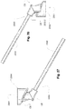
- the coupler may include a coupler body with a plurality of pneumatic channels.
- the coupler may also include first and second port connectors.
- the first and second port connectors may be configured on the coupler body for connection to a respiratory treatment apparatus at a ventilator connection end of the coupler body.
- the coupler may also include first and second conduits.
- the first and second conduits may be integrated with the coupler body and may be configured as pneumatic channels linked to the first and second port connectors respectively.
- the coupler may further include an alignment protuberant of the coupler body. The alignment protuberant may be configured to limit orientation of the first and second port connectors to only one connection configuration with the respiratory treatment apparatus.
- the alignment protuberant may include a connection ring for insertion within a housing channel of the respiratory treatment apparatus.
- the alignment protuberant may include a cylindrical chamber.
- the first port connector may be formed in an offset position within an interior portion of the cylindrical chamber.
- the second port connector may be formed in an exterior portion of the cylindrical chamber.
- the first port connector may include a gas channel for an expiratory pressure from a respiratory mask.
- the second port connector may include a PEEP control gas channel for a proximal valve.
- the connection ring of the alignment protuberant may include a chamfered cylinder. A surface of the chamfered cylinder may be configured for alignment with an exterior housing surface of the respiratory treatment apparatus.
- the coupler body may include a bend to angle a direction of the pneumatic channels of the coupler.
- Some examples of the technology may involve a method for maintaining operation of a ventilator.
- the method may include removing a pneumatic block from a compartment of a ventilator housing.
- the ventilator may be located in a patient environment.
- the pneumatic block may include any one or more of a casing, a volute assembly, a blower and air passages, sensors and/or an integrated calibration record.
- the method may further include inserting a pneumatic block into the compartment of the ventilator housing, and testing operation of the ventilator in the patient environment.
- the inserting may include returning the removed pneumatic block to the ventilator housing for operation of the ventilator after servicing.
- the testing operation of the ventilator may be with the returned pneumatic block.
- the method may include substituting a second pneumatic block in the ventilator housing for the removed pneumatic block. The testing operation of the ventilator may be with the second pneumatic block.
- the method may include servicing the removed pneumatic block for reuse.
- the servicing the removed pneumatic block may include cleaning the pneumatic block.
- the servicing the removed pneumatic block may include calibrating operation of one or more components of the pneumatic block, such as storing calibration data in calibration record of the block.
- the servicing may be performed in the patient environment.
- the servicing may be performed away from the patient environment contemporaneously with the ventilator being operable in the patient environment.
- the method may include pre-calibrating the inserted pneumatic block prior to the inserting.
- the technology may include a pneumatic block apparatus for removable insertion within a ventilator housing.
- the pneumatic block apparatus may include a casing including air passages; a volute assembly; and a blower coupled with the volute assembly.
- the casing may enclose the volute assembly.
- the air passages of the casing may connect air ports on the volute assembly.
- the pneumatic block apparatus may also include an integrated calibration record.
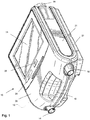
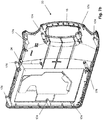
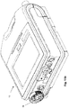
- FIGURES 1 to 4 show a ventilator 10 including a housing 12, an expiration air inlet port 14 and an inspiration outlet port 16.
- the ports 14 and 16 are connectable to tubes (not shown) which may be inserted into the trachea of a patient, to a face or nasal mask that fits over the nose or mouth or both of a patient, or otherwise attaches to the patient to assist with breathing.
- the housing for the ventilator may be portable and include a handle 18 for carrying the ventilator.
- the housing may have an upper housing case 20, a chassis 21 and a lower housing case 22 that are coupled together to form the external faces of the ventilator.
- the housing may have other configurations such as only comprising two component parts with an upper and lower casing or may have more than three component parts.
- the chassis 21 as seen in Figs. 5a and 5b may provide the structural skeleton for the ventilator assembly.
- the chassis 21 may include an inlet filter support 176 and inlet seal support 178 which are adapted to receive an inlet filter assembly 36 and inlet seal 38 respectively described in more detail below.
- the inlet seal 38 is also configured to couple to an inlet to a pneumatic block module 56.
- the inlet seal 38 is formed of a compliant material such as silicone, the inlet seal may be over moulded onto the inlet of the pneumatic block module 56.
- the chassis 21 may also comprise a pneumatic block seat into which the pneumatic block module 56 is located for ease of alignment and assembly of the pneumatic block module 56 within the housing.
- the chassis 21 also may include a portion of the handle 18.
- the rear of the chassis 21 may include a range of interfaces for a variety of connections and switches on the rear panel. For example, interfaces for electrical connectors, switches, data connections and oxygen connections.
- the chassis 21 also provides a number of interfaces to locate and retain components of the ventilator 10 such as a cooling fan 68, PCB 86, and components of an expiratory portion 31.
- the expiratory portion 31 of the chassis 21 comprises a positive end expiratory pressure (PEEP) supply port 172, a sensor filter interface 168 and an expiratory flow sensor interface 170 as seen in Figure 5a .
- the PEEP supply port 172 may be connected via a tube to a port of a PEEP electrovalve 140 to provide a pneumatic connection from a PEEP blower 124 to an expiratory interface module 200 as required to control the PEEP during expiration.
- a replaceable sensor filter may be inserted into the sensor filter interface 168 to protect sensors located on the main PCB from contamination from the expired gas.
- An expiratory flow sensor may be located within the expiratory flow sensor interface 170 (shown in Fig. 5a ) to measure the flow rate of the expired gas.
- the expiratory portion 31 is configured to receive an expiratory seal 70 that is adapted to retain and seal the expiratory sensor filter, expiratory flow sensor and provide a connection to the PEEP supply port 172 as described in more detail below.
- the expiratory portion 31 of the ventilator 10 is configured to allow the insertion of an expiratory interface module to receive the expired gas from the patient, such as the expiration air inlet port 14.
- the different expiratory interface modules include an expiratory valve 200 and an expiratory adaptor 202 (see Figs. 19a-19d and 21a-21d respectively).
- the lower housing case 22 includes a battery compartment 60 to locate and interface with a removable battery (not shown) and to provide the battery connector interface 62.
- a removable battery cover 52 is provided on the outer bottom surface to allow access to insert or remove the battery.
- a removable expiratory cover 48, an oxygen sensor cover seat 54S to receive an oxygen sensor cover 54 (shown in Fig. 5a ) and grills 44 to allow component heat venting are also provided on the outer bottom surface as described in relation to Fig. 4 below.
- the lower housing may also include an anti-slip foot or grip surface or one or more anti-slip or grip feet 53, such as a thermoplastic polyurethane (TPU) foot, on the outer bottom surface to prevent the ventilator 10 from slipping off a smooth surface.
- the anti-slip or grip feet 53 may also raise the ventilator 10 to prevent spilt water from pooling under the bottom of the ventilator.
- a portion of the handle 18 is also located within the lower housing case 22.
- the upper housing case 20 provides the top face of the ventilator 10 and an interface to receive a user interface display device 24.
- the housing may include a computer or processor driven user interface display device 24, such as a liquid crystal display (LCD) adapted to receive touch inputs for the computer.
- the display device may be flush with a top surface of the housing to be easily visible while the ventilator is in use.
- An alarm indicator light bar 26, such as a light emitting diode (LED) light bar, and a button 28 for disabling an audio or visual alarm may be adjacent the display.
- LED light emitting diode
- other known user interface systems may be used such as screens, buttons, dial, keys or combinations thereof.
- the chassis 21, lower housing case 22 and upper housing case 20 may comprise a plurality of screw bosses 174 that may be coupled together for assembly of the complete ventilator housing 12.
- the chassis 21 is assembled between the upper housing case 20 and the lower housing case 22.
- the screw bosses 174 may be configured to facilitate ease of assembly by having screw bosses 174 of differing lengths that are configured to couple to specific complementary screw bosses 174 on one of the other housing components.
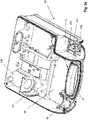
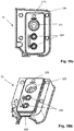
- Fig. 2 illustrates a ventilator 10 including an expiratory gas routing module adapted for removable insertion within the expiratory portion of the apparatus.
- the expiratory portion may be a compartment of the apparatus as will be explained in more detail herein with reference to the figures.
- the compartment includes a plurality of gas port connections in a particular fixed interface configuration (e.g., a molded structure) to permit insertion of different gas routing modules within the compartment using mating gas ports interfaces.
- each expiratory gas routing module may be configured with several distinct internal structural flow channels or gas pathways that may serve different functions, and may do so without tubes, depending on the purpose of the module.
- the pathways of the module lead to a fixed gas ports interface of the module for coupling with the structure of the gas ports interface of the expiratory portion compartment such as with a seal.
- the module may be easily inserted into the expiratory portion to couple with the expiratory portion's gas ports interface so that the respiratory pressure apparatus can deliver different treatment protocols in conjunction with the inserted module.
- the gas ports interface of the module has a standardized configuration (size and positional location) to permit a simple insertion of each different module into the complementary gas ports interface of the expiratory portion compartment depending on the desired functionality of the respiratory treatment apparatus.
- the module structure and the compartment structure with their fixed complementary gas ports interfaces permit the module to be plugged or installed into the compartment such that multiple gas connections may be fitted together substantially simultaneously rather than separately plugging in tubes for each gas port.
- Such complementary fixed structural interfaces for multiple gas ports helps to simplify assembly. Assembly may also be accomplished more rapidly since the structure of the module will only fit in one aligned position within the structure of the compartment. Inaccurate gas couplings, such as when tubes may be connected to the wrong ports, may thus be avoided.
- the expiratory gas routing module is an expiratory valve 200 connectable within the expiratory portion 31.
- the expiratory valve which is described in more detail herein in reference to FIGs. 19 and 20 , includes an expired gas output port 240.
- the expiratory gas routing module may be an expiratory adapter 202 (not shown in Fig. 2 but which is described in more detail herein with reference to FIGS. 21 and 22 ), which also fits within the expiratory portion 31.
- the expiratory adapter 202 includes a Positive End Expiratory Pressure (PEEP) control port 246 that may be located on the front of the housing 12 and proximate to the adapter pressure inlet port 244.
- the PEEP control port may be used in conjunction with the adapter pressure inlet port 244 when the ventilator is used in a PEEP operating mode.
- PEEP Positive End Expiratory Pressure
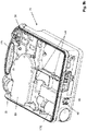
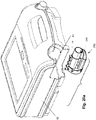
- the rear of the housing 12 may include an a filter assembly 36 (described in more detail herein in reference to Figs. 9 , 10 and 11 ).
- Air to be pumped into the lungs of the patient is drawn into the air inlet associated with the filter assembly.
- the air passes through a permeable filter membrane in the filter and enters an air passage for air flowing to the patient.
- the rear of the housing may include data connections 47 for communications with digital devices such as computer networks, alarm systems, a pulse oximeter (e.g., spO 2 ) and digital recording media.
- An electrical power connection 49 and an on-off switch 51 may also be positioned at the rear of the housing.
- a input grill 44-I provides an inlet for air to cool components and permit dissipation of the heat generated by operation of the internal components (e.g., blower motors and CPU). Movement of the heated air across internal components may be driven by a cooling fan 68 in the housing, which may be near a heated air output grill 44-0 (shown on bottom of housing in Fig. 4 ).
- an oxygen (O 2 ) inlet port 46 may be at the rear of the housing, which permits coupling with an oxygen source.
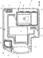
- FIGURE 4 shows a bottom of the ventilator housing.
- the removable expiratory cover 48 which serves as an external access hatch, provides access to and protection for the compartment of the expiratory portion or section of the housing. Removing the expiratory cover 48 provides access to any inserted expiratory gas routing module as well as the expiration air inlet port 14. It also allows for easy removal and replacement of the expiratory gas routing module such as the expiratory valve or expiratory adapter.
- the expiratory cover 48 may be tightened to the housing to reduce excess play by a latch dial 50L that may be turned with the fingers.
- the latch dial might serve to lock the latch from releasing.
- An optional latch release button 50R may be operated to disengage the expiratory cover.
- the release button 50R may be depressed to unlatch the expiratory cover 48.
- a skilled addressee would understand that alternative ways of removably securing and coupling the expiratory cover 48 to the housing may also be utilized.
- the bottom of the ventilator housing may also have removable battery cover 52 for a replaceable battery and an oxygen sensor cover 54 which may be removed to access an oxygen sensor 64.
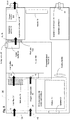
- FIGURE 5a shows a construction of the chassis 21 which may be organized according to the schematic diagram of the interior of the housing 12 shown in FIGURE 8 , which indicate the location of many of the components of the ventilator when installed in the casing.
- the interior of the housing is arranged with one or more dividers or walls to create various compartments that provide discrete sections for components that may serve as functionally compartmentalized areas, such as the inspiratory portion or the expiratory portion, the oxygen sensor compartment etc.
- Such a specialization of components into discrete areas can serve to simplify assembly and servicing of the apparatus as well as provide a way to segregate components to impede access to some components when access is only necessary for other components.
- a pneumatic block module 56 (not shown in Fig. 5a ) that includes one or more blowers for generating treatment pressure may be easily removed and replaced from the pneumatic block mounting seat 58 (shown in Fig. 5a ) in the housing.
- the pneumatic block module 56 may be inserted into such a molded seat in the chassis 21 assembly and may rest on shock absorbers or elastomeric supports to protect the module and/or reduce sound vibration.
- the walls of the seat which conform to the shape of the perimeter of the pneumatic block, may serve to align and support the block in its particular assembled position. As shown in FIG.
- the pneumatic block module is seated such that its air passages are aligned with the filter assembly 36 at the air inlet 34, the inspiration outlet port 16 and the oxygen supply path 43.
- Arrows indicate the air flow 35 path and arrows indicate the oxygen flow 45 path through the ventilator 10.
- the air flow 35 enters via the air inlet 34 and travels through the filter assembly 36 and inlet seal 38 into an inlet muffler 39 of the pneumatic block module 56.
- an oxygen source may be attached at the oxygen inlet port 46 and the oxygen flow 45 is directed through the oxygen supply path 43 and an oxygen seal into the pneumatic block module 56 where it is combined with the inlet air flow 35 within the inlet muffler 39.
- the air flow 35 is pressurized by a main blower 104 as described in more detail below.
- the pressurized air/oxygen flow 35, 45 are directed out of the pneumatic block module 56 via outlet muffler 84 and through the main seal 122 into the inspiratory portion 33 and then out the inspiration outlet port 16 to be delivered to the patient interface (not shown) via an air delivery conduit (not shown).
- An oxygen sensor 64 which may be located in an oxygen sensor compartment of the inspiratory portion 33, measures the amount of oxygen being delivered to patient.
- the oxygen sensor 64 may be mounted in the housing 12 such that it is easily replaced and adjacent the inspiration outlet port 16.
- the oxygen sensor detects the oxygen level of the air being pumped to the patient.
- Data from the oxygen sensor may be used to trigger alarms related to oxygen concentration and to provide data to the microprocessor to display the oxygen concentration on the user interface.
- the amount of oxygen supplied may be controlled by adjusting the known volumes of air and oxygen supplied to the patient. However, the oxygen sensor may also optionally be used to regulate the amount of supplemental oxygen to be supplied through the oxygen inlet port 46.
- An oxygen sensor cover 54 (shown in Fig. 4 ) on the bottom of the housing is removable to provide access to the oxygen sensor contained within an oxygen sensor compartment of the housing.
- the oxygen sensor fits in a mount within the housing and adjacent to the inspiration outlet port 16. A portion of the air flowing through the inspiration outlet port 16 is sensed by the oxygen sensor.
- the sensor generates data signals indicating the oxygen level of the gas.
- the data is conveyed by wire to a data connection which conveys the data to a processor.
- the processor analyzes the data to determine the amount of supplemental oxygen to be added to the air being pumped to the patient.
- the oxygen source may be a low pressure oxygen supply or a high pressure oxygen supply.
- an oxygen regulator (not shown) may be located within the oxygen supply path 43 to reduce the pressure from the high pressure oxygen source before the oxygen enters the inlet muffler 39.
- the oxygen inlet port 46 may be adapted to couple to a range of different oxygen connection adaptors to allow the connection of different types of oxygen connectors used in different jurisdictions including but not limited to male or female diameter index safety system (DISS), sleeve indexing system (SIS), National Institute of Standards Technology (NIST) and Association Francaise De Normalisation (AFNOR).
- DISS male or female diameter index safety system
- SIS sleeve indexing system
- NIST National Institute of Standards Technology
- AFNOR Association Francaise De Normalisation
- a high pressure oxygen source may be provided after the main blower 104 such as within the outlet muffler 84 where it is mixed with the pressurized air source.
- the high pressure oxygen may be used to provide the pressure source for the gas flow to the patient.
- pneumatic block module 56 is schematically shown as a rectangular shape it is to be understood that the pneumatic block module 56 may have any shape including a non-symmetrical shape that conforms to a seat in the housing and would minimize the possibility that the pneumatic block module 56 is improperly inserted into the housing.
- the main printed circuit board (PCB) or PCB 86 may be assembled and mounted to the chassis 21 and located between the chassis 21 and the lower housing case 22.
- the electronic components of the main board may include a processor, electrical connectors to convey data signals from the pneumatic block module 56 such as an electrical power and data connector for the blower which provides pressurized air to the inspiration outlet port 16.
- the electrical connectors provide power and signal paths between the electronic components on a PCB in the pneumatic block module 56 and the electronic components on the main PCB in the housing.
- the electronic components of the main board may also include a data and power connector for any sensors, such as the oxygen sensor.
- the electronic components in the housing may control a generation of images for the display device, sound signals for a speaker 61, such as for producing audible alarms, detect signals from pressure and oxygen sensors, and control the rotational speed of the blower.
- the chassis 21 may include a pneumatic block mounting seat 58 that may conform to the perimeter of the pneumatic block module 56.
- the chassis 21 may also provide a filter seat and/or a compartment (shown as inlet filter support 176) for the inlet filter assembly 36, and other mounting seats for the low pressure oxygen connection assembly, a cooling fan 68, and a deformable expiratory seal 70, which is described in more detail herein with reference to Fig. 18 .
- the chassis 21 may also include embedded or integrated air passages and ports that may be molded within the chassis structure such as for conveying air between sections or compartments of the chassis. For example, air at a known pressure may be channeled through passages of the chassis from the pneumatic block module to the PEEP air supply.
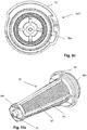
- FIG. 9a shows a perspective view of a filter assembly 36 and Figs. 9b and 9c show front and rear views of the filter assembly 36 respectively.
- the filter assembly 36 includes an inlet filter housing 32 adapted to receive an inlet filter 37 (see Fig. 10a ) therein.
- the air inlet 34 for the ventilator 10 is formed in the front outer surface of the inlet filter housing 32.
- the air inlet 34 comprises a grill or grate 74 configured to prevent large particles from entering the filter assembly 36.
- the grate 74 is angled downwards to substantially prevent or reduce water ingress into the ventilator.
- the downwardly angled grate is structured to direct any water to run off and not enter the inlet filter assembly 36.
- the grate 74 also prevents objects or fingers from being inserted into the filter assembly 36.
- a housing protrusion 76 extends from the outer surface of the air inlet 34 and is structured to prevent objects from completely blocking the air inlet 34.
- the opposing surface of the housing protrusion 76 forms a cone 76a (shown in Fig. 9c ) within the filter housing cover 32C that is adapted to receive a corresponding filter protrusion 92.
- a collar 72 surrounds the air inlet 34 and provides a locking mechanism such as a bayonet, threaded or screw locking mechanism to secure the filter assembly 36 to the ventilator housing 12 as described in more detail below.
- the inlet filter housing 32 may be formed as a cylinder portion 82 that is configured to receive the inlet filter 37.
- the cylinder portion 82 preferably has a substantially constant diameter of about 20-60 mm, more preferably about 30-40 mm, such as about 34 mm, 35 mm or 36 mm along the length of the cylinder portion 82.
- the length of the cylinder portion may provide a muffling function to reduce noise being transmitted back through the inlet.
- the length of the cylinder portion is preferably about 30-100 mm, more preferably 50-80 mm, or 60-70 mm, such as 60mm, 61mm, 62mm or 64 mm.
- a cylinder portion 82 may be formed with other dimensions.
- Figs 10a to 10d illustrate the inlet filter 37 according to an example embodiment.
- the inlet filter 37 comprises a filter cage 88 having a porous filter material 90 coupled thereto.
- the filter cage 88 provides a structural support for the filter material 90 and includes a tip end 88t and a base end 88b.
- the inlet filter 37 may have a frustoconical shape to maximize the filtering area while providing a relatively small opening on the exterior of the ventilator housing for the incoming air.
- the filter material 90 may be fixed to the filter cage 88 by injection over moulding the cage onto the filter material. However, other methods of coupling or fixing the filter material 90 to the filter cage 88 may be implemented.
- the porous filter material 90 may be arranged in pleats or be unpleated and it may form the sidewalls of the frustoconical shaped inlet filter 37.
- the filter material 90 filters atmospheric air flowing in through the air inlet 34 to remove dust and other particles from the air before the air is pumped through the ventilator 10 and subsequently to a patient.
- the filter material may optionally have a filtration cutoff level of at least 10 micrometer ( ⁇ m) filters, such as 8 ⁇ m, 7 ⁇ m or 6 ⁇ m.
- the portion of the inlet filter 37 including the filter material 90 preferably has an diameter of about 10-30 millimeters (mm), more preferably 15-20 mm, such as 17-19 mm or 18 mm at the tip end 88t of inlet filter and a diameter of about 20-55 mm, more preferably about 25-35 mm, such as about 30 mm, 31 mm or 32 mm at the wider base end 88b of the inlet filter.
- the inlet filter 37 is inserted into the open or inner end of the cylinder portion 82 of the inlet filter housing 32 and may have an interference fit.
- a filter flange 94 at the base end 88b of the inlet filter 37 forms a stop against the outer rim of the open or inner end of cylinder portion 82 to provide for the correct level of insertion.
- a filter protrusion 92 at the tip end 88t of the inlet filter 37 is received within the cone 76a within the filter housing cover 32C.
- the filter cage 88 and the inlet filter housing 32 may be formed of a plastic material such as polycarbonate or polypropylene, and may be formed by moulding.
- the filter material 90 may be a hypo-allergenic air filter material, such as a polyester fibre that has been needled and thermally bonded.
- the filter material may be, for example, a foam, paper, polyester, woven, unwoven, pleated, unpleated etc.
- the filter assembly 36 is structured to be removably inserted into an inspiratory portion compartment of the chassis 21 of the housing 12 of the ventilator 10 to allow easy replacement and inspection of the inlet filter 37. Thus, it may be inserted and removed from a filter compartment FC of the chassis.
- the collar 72 of the inlet filter housing 32 may include one or more lug or pin 78 to engage an inlet opening 80 in the rear of the housing 12.
- the inlet opening 80 on the rear of the ventilator comprises one or more corresponding divot or slot 80a into which one or more pins or lugs of the cover may engage.
- Other removable fastening mechanisms such as a threaded fastener, screw, snap locks etc, may be used to removably couple the filter assembly 36 to the ventilator housing 12.
- the filter assembly 36 is inserted into the inlet opening 80 in the ventilator housing 12 and the collar 72 is turned, preferably by hand, to engage the lug/pin 78 of the filter assembly 36 to the divot or slot 80a of the ventilator housing 12 to securely lock the filter assembly 36 to the ventilator housing 12 as shown in Figs. 11a and 11b .
- the filter assembly 36 sealingly engages with the inlet seal 38 within the ventilator 10 to form an airtight radial seal.
- the inlet filter 37 includes a lead-in taper on the base end 88b that facilitates the engagement with the inlet seal 38.
- the inlet seal 38 ensures that the incoming air flow 35 is limited to the air path within the ventilator and cannot contaminate the remainder of the chassis.
- the collar 72 is turned in the opposite direction to disengage the lugs or pins 78 from the slot 80a to allow the filter assembly 36 to be pulled out of the filter compartment of the ventilator housing 12.
- the complete filter assembly 36 may be completely replaced to replace the inlet air path, for example for multiple patient use.
- the inlet filter 37 may be replaced as required for cleaning or maintenance of the ventilator.
- the pneumatic block module 56 may include a substantially rigid outer casing and may be formed of heat conducting material for good thermal conductivity.
- it may be formed of aluminum alloy, magnesium, or other material suitable for providing a structural support housing for the module as well as heat conductivity.
- the outer casing may be formed of metal such as die cast aluminum.
- the housing may be formed in multiple parts, for example three parts: a main chassis 184, a bottom lid 186 and a top lid 182.
- the rigid outer casing provides a structural housing for the air path or passages, blower, electronics and other components of the pneumatic block module 56.
- a seal may be coupled to one or more of the casing parts to form a pneumatic seal around the outer perimeter of the pneumatic block module 56.
- the bottom lid 186 may include an overmoulded silicone seal around its perimeter.
- the pneumatic block module contains a substantial portion of the air passages within the ventilator 10 and may be replaced for ease of servicing.
- Fig. 12 is a schematic of the internal components of the pneumatic block module 56.
- the pneumatic block module 56 includes the main blower 104 with volute assembly 108, an inlet non-return valve assembly 114, an optional oxygen inlet port 144, a positive end expiratory pressure (PEEP) blower or PEEP blower 124, outlet muffler 84, safety valve 85, pressure sensor 128, flow sensor 130 and flow element 132 and a PEEP pressure sensor 142.
- the volute assembly 108 forms the majority of the airpath and performs some of the critical functions of the pneumatic block module 56.
- the sidewalls of the main chassis 184 include openings for the wires of the electrical connections, the expiratory pressure or PEEP pressure tube 188, and for air passages associated with the oxygen supply.
- a deformable plastic grommet may be configured to fit in the openings of the casing sidewalls to shield the connection wires from potentially sharp edges on the metal openings and provide a seal between the inside and outside of the main chassis 184.
- Fig. 13 shows an exploded view of the pneumatic block module 56 and the components therein.
- the bottom lid 186 is sealingly coupled to the main chassis 184 to form the lower outer surface of the pneumatic block module 56.
- the main chassis 184 may include electrovalve interfaces 118 to support the pressure release electrovalve 116 and the flow control electrovalve 120 that are configure to communicate with and control the non-return valve assembly 114.
- a main seal 122 (which is also shown in Fig. 16 ) is coupled to the main chassis 184, the main seal 122 provides a surface 190 to join multiple seals between the main chassis 184 and the volute assembly 108 (upper volute 110 and lower volute 112) whilst also providing suspension and/or vibration isolation for the main blower 104.
- a seal slit 195 may be present within surface 190 to accommodate tolerance variations between the volute assembly 108, pneumatic block main chassis 184 and main seal 122 and to ensure that the sealing areas are not deformed.
- the seals 198 and 194 together provide the seal between the low pressure inlet side of the main blower and high pressure outlet side of the main blower.
- the air flow 35 and oxygen flow 45, if present, are mixed within the low pressure inlet side.
- a sealed inlet chamber is formed between main seal and a seal on the bottom lid 186.
- the main seal 122 may also provide one or more of the following sealing features: to provide the safety valve sealing interface using seal 192 between the safety valve 85 and the aperture in the lower or bottom lid 186 to atmosphere for the safety valve; and to provide the volute outlet sealing interface 194 for the volute outlet 134.
- the main seal 122 may also provide a volute grommet 196 that is configured to couple to the rear volute support 152 on the volute assembly 108 to help support the volute within the pneumatic block module 56.
- the non-return valve assembly 114 comprises a membrane NRVM that is retained to the NRV chamber using a clamping ring.
- the non-return valve assembly 114 is assembled in the lower volute 112 and is located adjacent the inlet to the main blower 104 to control the level of flow at the blower inlet.
- the non-return valve may include the non-return valve system as described in the co-owned pending PCT application PCT/AU2011/000341 filed 25 March 2011.
- the main blower 104 is retained and sealed by the volute assembly. Any form of blower that may provide the required pressures and flow required for ventilation may be utilized, for example a single stage blower or a multistage blower. A blower as described in PCT application PCT/EP2010/066498 filed 29 October 2010 and published as WO 2011/051462 may be used.
- a blower suspension 106 is provided above the main blower to provide vibration isolation and/or support to the main blower 104.
- the blower suspension 106 may also act as a heat sink to facilitate the conduction of heat away from the main blower and to the top lid 182.
- the blower suspension may be formed of a conductive elastomer.
- the top lid 182 may be formed of a heating conducting material to facilitate the release of the heat away from the main blower 104.
- a PEEP blower 124 includes a PEEP impeller 127 and PEEP volute 125 and is configured to provide a pressure source during expiration as required to an expiratory valve 200 (described in more detail below with reference to Figs. 21 and 22 ) when located within the compartment of the expiratory portion 31.
- the PEEP blower 124 is supported by a PEEP suspension 126.
- the PEEP suspension may be formed of a compliant material to provide vibration isolation and to allow cooling around the PEEP blower 124, for example the PEEP suspension 126 may be formed of silicone, preferably moulded silicone.
- a PEEP electrovalve 140 controls the supply of the pressure from the PEEP blower 124 to the expiratory portion 31.
- a PEEP pressure tube 188 is coupled between the PEEP electrovalve 140 and the PEEP supply port 172 (shown in Fig. 5a ) in the expiratory portion 31 to provide the PEEP pressure source.
- a sensor PCB 166 comprising sensors, such as pressure and/or flow sensors, is coupled via a sensor seal 136 to the upper volute 110 to provide the sensor signals, such as pressure and/or flow signals, for the gas flow as it exits the volute outlet 134.
- the volute assembly 108 may be assembled from one or more moulded components, such as an a upper volute 110 portion and a lower volute 112 portion that are coupled together.
- the volute assembly 108 may include a plurality of interfaces to provide ease of assembly of the different pneumatic connections required within the pneumatic block module 56.
- the volute includes the main blower volute 158 that is adapted to receive the main blower 104 and provides the volute area around the main blower 104 (not shown) and the main airpath between the main blower 104 and the volute outlet 134.
- the volute may also include a PEEP blower support 162, PEEP electrovalve support 160, pressure sensor ports 154, flow sensor ports 156 and the volute outlet 134.
- the volute outlet 134 may comprise a flow element 132 (not shown in Fig. 14 ) to facilitate measuring the flow exiting the volute assembly 108. Expired gas flow is routed through the flow element 132 for measuring a differential pressure across the flow element 132.
- the volute may include a non-return valve (NRV) chamber 146 that is adapted to receive a non-return valve assembly 114 (not shown in Figure 15 ).
- a NRV pressure connector tube 148 is configured to conduct pressure to the NRV chamber 146.
- the outlet muffler 84 and a safety valve support 150 may also be formed in the volute.
- the volute assembly 108 is assembled to the chassis of the pneumatic block module 56 using supports such as the rear volute support 152.
- a sensor PCB 166 may be coupled to the volute assembly 108 via one or more PCB screw bosses 164.
- the safety valve 85 is located at the safety valve support 150 within the outlet muffler 84. The air then passes through the flow element 132 and out of the volute outlet 134.
- Figs. 17a to 17c show an embodiment of the sensor seal 136.
- the sensor seal 136 is configured to be coupled between components on the volute assembly 108, such as the sensor ports and electro valve port, and to integrated sensors of the sensor PCB 166.
- the sensor seal 136 is formed of a compliant material such as silicone and provides sealing connections between sensors on the PCB and the components on the volute assembly 108 and from the PEEP blower 124 to the PEEP electrovalve 140.
- the sensor seal 136 may also serve to mount the sensor PCB 166 to the volute assembly 108.
- the sensor seal 136 may also protect the sensor PCB 166 against shocks and vibration.
- the connections between the pressure sensors and the air passages in the volute assembly are quickly and reliably formed. Furthermore, the sensor PCB 166 and the arrangement of pressure sensors thereon may allow for a unique mounting orientation onto the sensor seal 136 which may minimize the risk of pressure sensors not being properly connected to the air passages in the volute assembly 108.
- the sensor seal 136 includes a first side 136a as shown in Fig. 17a that is configured to engage with the pressure sensor ports 154, flow sensor ports 156 and the PEEP electrovalve 140 within the PEEP electrovalve support 160 on the volute.
- a second side 136b as shown in fig, 17c , is configured to engage with sensors located on the sensor PCB 166.
- the first side 136a includes two flow element bypass ports 214, an entry port and an exit port that are connected to the flow sensor ports 156 on the volute.
- the two flow element bypass ports 214 are coupled to the flow element on the sensor PCB 166 to allow a bypass flow of the outlet gas flow to be measured to provide a flow signal for the outlet gas flow.
- the first side 136a also includes an outlet pressure port 210 and an inspiratory/expiratory pressure port 204 that are engaged with the pressure sensor ports 154 in the volute.
- the second side 136b provides an outlet pressure sensor seal 206 and an inspiratory/expiratory pressure sensor seal 212 that are configured to pneumatically engage with the outlet pressure sensor and the inspiratory/expiratory pressure sensor located on the sensor PCB 166 to allow pressure measurements of the outlet gas flow and the expired gas flow respectively.
- the sensor PCB may also be secured to the volute assembly 108 by fasteners, e.g., screws.
- a PEEP electrovalve port 216 is also located on the first side 136a of the sensor seal 136 and is configured to engage with the PEEP electrovalve 140 that is located within the PEEP electrovalve support 160 on the volute.
- the second side 136b of the sensor seal includes a PEEP pressure port 208 configured to connect to an outlet of the PEEP blower 124, thus in use the PEEP pressure port 208 is configured to provide a PEEP pressure supply to the PEEP electrovalve 140 for controlling the expiratory valve 200.
- housing the majority of the air passages and pneumatic connections within the outer casing of the pneumatic block module 56 By housing the majority of the air passages and pneumatic connections within the outer casing of the pneumatic block module 56, the number of air tubes exposed outside of the casing is minimized. Housing the pneumatic connections within the casing reduces any risk that tubes become disconnected, leak or are incorrectly connected to air passages. Further, housing the pneumatic connections in the casing of the pneumatic block reduces the complexity of the components within the housing, in that some of the complexity from the pneumatic connections may be confined to the pneumatic block module 56.
- the filter assembly 36, inlet seal 38, pneumatic block module 56, inspiration outlet port 16 and the components of the expiratory portion 31 are disconnected and/or unplugged from the housing and replaced.
- the expiratory portion 31 one or more of the following components may be replaced: expiratory valve 200, expiratory adaptor 202, expiratory seal 70, sensor filter, and flow element.
- expiratory valve 200 expiratory valve 200
- expiratory adaptor 202 expiratory seal 70
- sensor filter sensor filter
- flow element There is no requirement to disconnect and then reconnect a plurality of tubes to make the pneumatic connections within the ventilator as the majority of such pneumatic connections are formed within the replaceable pneumatic block module 56.
- a new filter assembly 36 is inserted into the inlet filter support 176 and a new inlet seal 38 is coupled to the inlet seal support 178.
- a new pneumatic block module 56 is attached to the housing 12, and coupled to the inlet seal 38 at the pneumatic block module inlet and to a new inspiration outlet port 16 at the pneumatic block module outlet.
- a new expiratory seal 70 (discussed with reference to Fig. 18 ), sensor filter, flow element and expiratory valve 200 or expiratory adaptor 202 may be inserted into the expiratory portion 31.
- Several air passage connections are formed by inserting the pneumatic block module into the housing. The additional air passage connections needed to be made after the module is in place in the housing may be relatively few.
- the PEEP pressure tube 188 is attached to expiratory portion 31. Consolidating the air passages in the pneumatic block module avoids the complicated nest of tubes and other air passages found in conventional ventilators.
- the expiratory portion 31 is adapted to receive the expired gas 55 from the patient.
- the expiratory portion may be configured as a compartment to receive a removable expiratory interface module, such as an expiratory valve 200 or expiratory adaptor 202 that may serve to route expiratory gas for various purposes.
- a removable expiratory interface module such as an expiratory valve 200 or expiratory adaptor 202 that may serve to route expiratory gas for various purposes.
- the chassis 21 includes some interfaces to receive a sensor filter and expiratory flow sensor.
- An expiratory cover 48 for the compartment of the expiratory interface module is a separable part of the housing 12.
- the expiratory cover 48 may include a release button 50R and latch dial 50L (see Fig. 4 ) which may be operated by hand to allow the cover to slide off from the housing. After the expiratory cover 48 is removed, the expiratory interface module may be lifted out of the housing.
- the compartment of the expiratory portion 31 may also be configured to receive an expiratory seal 70 that conforms to an internal surface shape of the compartment.
- the seal may be adapted to retain and seal an expiratory sensor filter, an expiratory flow sensor and provide air ports to connect to the expiratory gas routing modules (e.g., expiratory adapter and expiratory valve), to the air passages in the housing 12
- the expiratory seal 70 is deformable and provides a structural support for the expiratory interface module and may shield the module from shocks and vibrations and also assist in minimizing the entry of dirt and contamination to the sensors and ports within the expiratory portion 31.
- FIGURES 18a to 18d show an example expiratory seal 70.
- the expiratory seal 70 is adapted to be inserted into the compartment of the expiratory portion 31 and forms a sealing interface between the gas ports interface of the chassis of the housing 12 and the expiratory gas routing module.
- the gas routing module may be inserted into the expiratory portion 31 and form a sealed interference fit with the seal and the gas ports interface of the compartment.
- An optional tab 218 may be provided on the expiratory seal 70 to facilitate ease of removal of the expiratory seal 70 by pulling the tab 218 to pull out the expiratory seal 70.
- the expiratory seal 70 has an irregular or unique outer shape to facilitate proper alignment for insertion into the expiratory portion 31.
- an aperture 226 may be formed between the expiratory seal 70 and the chassis 21 within the expiratory portion 31 to form an alignment feature for insertion of the expiratory interface module (e.g., expiratory valve 200 or expiratory adapter 202).
- the expiratory seal 70 may provide a plurality of sealed pneumatic channels, such as a PEEP supply channel 220, an expiratory pressure sensor channel 222 and a pair of expiratory flow sensor channels 224.
- the PEEP supply channel 220 is configured to connect between the PEEP supply port 172 formed in the expiratory portion 31 of the chassis 21 and the PEEP supply port on the expiratory interface module (e.g., expiratory valve 200 or expiratory adapter 202).
- the PEEP supply channel provides a route for the PEEP gas flow.
- An expiratory flow sensor and a sensor filter for a pressure sensor sit within an expiratory portion compartment of the chassis.
- the expiratory flow sensor interface 170 and sensor filter interface 168 in the chassis 21 are shown in Fig. 5a .
- the expiratory seal 70 is seated over the flow sensor and sensor filter.
- the expiratory pressure sensor channel 222 forms a channel between the sensor filter and a pressure port on the expiratory interface module.
- the pair of expiratory flow sensor channels 224 provides a bypass flow between a flow element that is located within the expiratory interface module for measuring the expiratory flow rate.
- the pair of expiratory flow sensor channels 224 are connected between a flow sensor and flow ports on an expiratory interface module.
- the channels 222, 224 provide conduits connecting the air passages in the expiratory interface module (e.g., expiratory valve 200) with sensors in the housing 12.
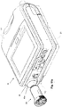
- FIGURES 19a to 19d and Figures 20a to 20c show an example expiratory valve 200 that is adapted as an expiratory interface module to be seated on the expiratory seal within the expiratory compartment.
- FIGURES 21a to 21d and Figures 22a to 22c show an example expiratory adaptor 202 that is alternatively adapted to be seated on the expiratory seal within the expiratory compartment.
- the expiratory valve 200 may include an expired gas inlet 238 adapted to be connected to an air delivery conduit (not shown) to receive gas expired by the patient.
- the expired gas passes through the expiratory valve 200 and exits to atmosphere through an expired gas outlet port 240.
- the expiratory valve 200 may comprise at least one alignment tab 228 to assist with correctly aligning and retaining the expiratory valve to the expiratory seal 70.
- the alignment tab 228 may be received within the aperture 226 created between the chassis 21 and the expiratory seal 70 when the expiratory seal is inserted into the chassis 21.
- the expiratory valve 200 comprises a PEEP pressure port 232, pressure sensor port 234 and a pair of flow sensor ports 230 that are aligned with the PEEP supply channel 220, expiratory pressure sensor channel, and expiratory flow sensor channels in the expiratory seal 70 when the expiratory valve 200 is seated on the expiratory seal 70.
- An expiratory flow element 236 may be located within the expired gas inlet 238 in an expiratory airflow path or channel between the pair of flow senhsor ports 230 and within the expiratory valve.
- the flow sensor ports 230 allow a flow sensor to detect the flow rate of the expired gas from the patient.
- the pressure sensor port 234 that connects with an internal channel of the expiratory valve allows the pressure of the expired gas to be sensed by a pressure sensor.
- the PEEP pressure port 232 is configured to receive a supply of pressurized gas from the PEEP blower 124 and channel the gas within the expiratory valve, the flow of which is used to control the operation of a PEEP membrane located within a removable valve cap 242 of the expiratory valve 200.
- the expiratory valve 200 may be inserted into the expiratory compartment so that the ventilator may serve as a dual limb ventilation system, i.e. separate inspiratory and expiratory gas delivery conduits are used.
- an inspiratory gas supply generated by the ventilator 10 is delivered to a patient interface device via an inspiratory gas conduit that is coupled to the inspiration outlet port 16.
- the patient expired gas is delivered back to the expiratory portion 31 of the ventilator 10 via an expiratory gas conduit.
- the expiratory valve 200 together with the PEEP blower 124 are adapted to regulate a positive end expiratory pressure during expiration.
- Figures 20a to 20c illustrate insertion of the expiratory valve 200 into the expiratory portion 31 of the ventilator 10 and the insertion of the expiratory cover 48 to retain the expiratory valve 200 within the compartment of the expiratory portion 31 of the ventilator 10.
- Figures 21a to 21d show an example of an expiratory adaptor 202 that is configured to be seated on the expiratory seal 70 within the compartment of the expiratory portion 31 of the ventilator 10.
- the expiratory adaptor has a complementary interface configuration to that of the expiratory valve 200 to facilitate insertion within the same compartment and same seal despite serving, in part, a different gas routing purpose.
- the expiratory adaptor may also comprise at least one alignment tab 228 to assist with correctly aligning and retaining the expiratory adaptor 202 to the expiratory seal 70.
- the alignment tab 228 may be received within the aperture 226 created between the chassis 21 and the expiratory seal 70 when the expiratory seal is inserted into the chassis 21.
- the expiratory adaptor 202 comprises a PEEP pressure port 232 and a pressure sensor port 234 in a similar manner to the expiratory valve 200.
- the expiratory adaptor does not comprise a PEEP membrane for controlling the PEEP pressure as this is provided in a proximal expiratory valve (not shown).
- the PEEP pressure port 232 routes the PEEP pressure from the PEEP blower 124 to the proximal expiratory valve via a tube that is coupled to an adaptor PEEP control port 246.
- a pressure measurement of the expired gas is made via delivery of a supply of the expired gas via another small tube connection to an adaptor pressure inlet port 244 that is connected within the expiratory adaptor 202 and routes expired gas to the pressure sensor port 234 for measuring of the pressure at the pressure sensor.
- ports 248 may be blank ports (e.g., no connecting channel) that can be used to assist in aligning and retaining the expiratory adaptor 202 in its sealed position with the expiratory seal 70.
- Insertion of the expiratory adaptor in the expiratory compartment permits the ventilator to serve as a single limb ventilation system with a proximal expiratory valve.
- an inspiratory gas conduit is connected to the inspiration outlet port 16 in a similar manner to that described above for the expiratory valve.
- there is no expiratory gas conduit as a proximal expiratory valve is connected proximal to the patient.
- the proximal expiratory valve releases the majority of the expired gas 55 at a location proximal to the patient.
- a pneumatic coupler 2300 may be adapted to serve as a removable connection for the ports of the ventilator's expiratory adapter 202 and conduits for the patient circuit or patient interface.
- Such a coupler may be adapted with a configuration to ensure this coupling with the multiple ports of the adapter 202 in only one manner so as to avoid an incorrect connection between the ports and the conduits of the patient circuit.
- the coupler 2300 may have a ventilator connection end 2301 and a patient circuit end 2303.
- the ventilator connection end 2301 of the coupler 2300 may include first and second port connectors 2302-1, 2302-2 and as such, serves as an pneumatic interface to the ventilator from, for example, a single patient circuit with a proximal valve.
- These ports will include first and second gas channels 2302-1-GC, 2302-2-GC.
- the first port connector 2302-1 of the coupler 2300 may be configured for coupling only with the adapter pressure inlet port 244 of the expiratory adapter 202, the port that senses patient pressure.
- the second port connector 2302-2 of the coupler 2300 may be configured for coupling only with the PEEP control port 246 of the expiratory adapter, the port for controlling PEEP pressure.
- Such a connection between the ventilator connection end 2301 of the coupler 2300 and the expiratory adapter 202 of the ventilator 10 may be, for example, by an interference fit at the ports.
- the coupler may also include an alignment protuberant, such as connection ring 2304, to enforce proper alignment of the ports and port connectors.
- the alignment protuberant may be configured for insertion, such as by interference fit, with a structure of the ventilator, such as a receiving channel RC of the housing of the ventilator.
- the collective structures may be configured to permit the insertion in only one orientation.
- the connection ring 2304 may be sized and configured for insertion within a receiving channel RC of the expiratory portion 31 (best seen in Figure 22C ).
- the first port connector may itself be cylindrical and may be located within a portion of the greater circumference of an inner cylindrical chamber 2344 (best seen in FIG.
- connection ring may be offset from a center of the connection ring (or offset from a central axis of the cylindrical chamber) as illustrated.
- the inner cylindrical chamber 2344 itself does not serve as a passage of gas channel for pressure or gas of the respiratory treatment system.
- the second port connector may also be cylindrical and may be located outside the circumference of the connection ring or otherwise outside the cylindrical chamber. In this way, a single coupler for multiple conduits may be configured for connection in only one alignment orientation so as to only permit a proper connection of multiple ports (e.g., two or more).
- the patient circuit end 2303 of the coupler may then have integrated conduits, in proper orientation, such as flexible tubes of the patient circuit that may include the patient interface (not shown).
- the conduits may be bonded to the coupler or may otherwise be formed therewith.
- One or more of these tubes may lead to or connect to a proximal valve (not shown).
- Such tubes may provide a pneumatic conduit for patient pressure signals (e.g., from a patient mask (not shown)) and pneumatic control pressure to the proximal valve from the ventilator.
- the expiratory conduit 2306 leads to the adapter pressure inlet port 244 via the first port gas channel 2302-1-GC of the coupler and the PEEP control conduit 2308 leads to the PEEP control port 246 via the second port gas channel 2302-2-GC of the coupler.
- the coupler may serve as a twin connection where each port connection is the same size and shape.
- the diameter and shape of the two points of contact of the first port connector 2302-1 and the second port connector 2302-1 can be the same.
- the may both have the same cylindrical connector and gas channel size. Nevertheless, the structural configuration of the coupler, as a whole, including the alignment feature will prevent any confusion concerning which port connector connects to which port of the expiratory adapter.
- conduits 2308, 2306 are not integrated or bonded with the conduits 2308, 2306, though they may be, a multiport coupler design may also be implemented at the opposing end to ensure that the conduits couple to ports of the patient interface and proximal valve properly, (e.g., in only one alignment orientation).
- the coupler 2300 may be formed of an elastomeric material.
- the elastomeric material may help to provide a sealed connection with the ventilator and the expiratory adaptor).
- the connector may also be designed to blend with the shape and form of the ventilator housing so as to make the coupled assembly as unobtrusive as possible.
- the connection ring 2304 may be a cylindrical structure that is chamfered on one curved end CE so when it is properly inserted it has a surface that conforms (e.g., the surfaces may be approximately flush) to an exterior surface of the ventilator housing profile.
- a coupler bend CB may be implemented to maintain the conduits in a close proximity to the housing. In this regard, the bend may serve to direct the gas channels of the coupler at an angle (e.g., a 45 degree bend, 90 degree bend, etc.).
Claims (16)
- Appareil de traitement respiratoire conçu pour fournir un flux de gaz respirable à un patient, comprenant une sortie d'air (16), une entrée d'air (14) et un module de bloc pneumatique (56), dans lequel le module de bloc pneumatique comprend :un châssis (184) ;un ensemble volute (108) comprenant un passage d'air d'entrée, une fixation (106) pour une souffleuse (104) et un passage d'air de sortie ;la souffleuse étant fixée dans la fixation de telle sorte qu'une turbine de la souffleuse est dans un passage de flux reliant le passage d'air d'entrée et le passage d'air de sortie ; etune gaine entourant l'ensemble volute, la gaine comprenant le châssis, dans lequel des passages d'air à l'intérieur de la gaine relient des ports d'air sur l'ensemble volute,dans lequel le passage d'air d'entrée de l'ensemble volute (108) est en communication fluidique avec l'entrée d'air et le passage d'air de sortie de l'ensemble volute est en communication fluidique avec la sortie d'air, et dans lequel l'appareil comprend en outre un joint principal (122) couplé au châssis (184) et fournissant plusieurs joints (198, 194, 192) entre le châssis (184) et l'ensemble volute,caractérisé en ce que le joint principal (122) a une surface (190) pour joindre les multiples joints, et les multiples joints (192, 194, 198) comprennent des joints (198, 194) fournissant un joint entre un côté entrée basse pression de la souffleuse et un côté sortie haute pression de la souffleuse, et un joint (192) fournissant une interface d'étanchéité de soupape de sécurité.
- Appareil de traitement respiratoire selon la revendication 1, dans lequel l'appareil est un ventilateur.
- Appareil de traitement respiratoire selon la revendication 1 ou 2 dans lequel l'ensemble volute (108) est un dispositif en plastique rigide moulé.
- Appareil de traitement respiratoire selon l'une quelconque des revendications 1 à 3, dans lequel la gaine est métallique et possède une partie inférieure et un couvercle supérieur.
- Appareil de traitement respiratoire selon l'une quelconque des revendications 1 à 4, dans lequel la gaine comprend un passage d'air entre l'entrée d'air et le passage d'air d'entrée de la volute.
- Appareil de traitement respiratoire selon la revendication 5, dans lequel le passage d'air dans la gaine est formé entre une plaque inférieure de la gaine et un couvercle pour la plaque inférieure.
- Appareil de traitement respiratoire selon l'une quelconque des revendications 1 à 6, comprenant en outre un ensemble filtre d'entrée amovible aligné avec l'entrée d'air, dans lequel l'ensemble filtre d'entrée amovible est maintenu dans une gaine comprenant l'entrée d'air, et la gaine et l'ensemble filtre d'entrée peuvent être retirés d'un boîtier de l'appareil de traitement respiratoire.
- Appareil de traitement respiratoire selon l'une quelconque des revendications 1 à 7 comprenant en outre un connecteur déformable intercalé entre l'ensemble volute et une carte de circuit imprimé, dans lequel des capteurs de pression sur la carte de circuit imprimé sont alignés avec des ports à travers le connecteur lorsque la carte de circuit imprimé repose sur l'ensemble volume et les ports sur le connecteur sont ouverts aux passages d'air dans l'ensemble volute.
- Appareil de traitement respiratoire selon l'une quelconque des revendications 1 à 8, dans lequel le joint principal (122) est adapté pour fournir également une suspension et/ou une isolation vibratoire à l'ensemble volute (108).
- Appareil de traitement respiratoire selon l'une quelconque des revendications 1 à 9, dans lequel le joint principal (122) comprend une fente de joint (195) à l'intérieur de la surface (190).
- Appareil de traitement respiratoire selon l'une quelconque des revendications 1 à 10, dans lequel une chambre d'entrée scellée est formée entre le joint principal (122) et un couvercle inférieur (186) de la gaine.
- Appareil de traitement respiratoire selon l'une quelconque des revendications 1 à 11, dans lequel le module de bloc pneumatique comprend une soupape de sécurité (85).
- Appareil de traitement respiratoire selon l'une quelconque des revendications 1 à 12, dans lequel le joint principal est adapté pour fournir une interface d'étanchéité (194) pour une sortie de volute (134) dans le passage d'air de volute de l'ensemble volute.
- Appareil de traitement respiratoire selon l'une quelconque des revendications précédentes, dans lequel le joint principal comprend un oeillet (186) conçu pour être couplé à un support arrière sur l'ensemble volute.
- Appareil de traitement respiratoire selon l'une quelconque des revendications 1 à 14, dans lequel le joint (194) pour la sortie haute pression est au niveau d'une ouverture d'une surface latérale du châssis (184).
- Appareil de traitement respiratoire selon la revendication 15, dans lequel le joint (198) pour le côté entrée de pression de la souffleuse est au niveau d'une ouverture d'une surface inférieure du châssis (184).
Priority Applications (2)
| Application Number | Priority Date | Filing Date | Title |
|---|---|---|---|
| EP17198437.0A EP3311869B1 (fr) | 2011-09-26 | 2012-09-26 | Appareil de ventilateur |
| EP20160198.6A EP3738637B1 (fr) | 2011-09-26 | 2012-09-26 | Coupleur pour un appareil de traitement respiratoire |
Applications Claiming Priority (3)
| Application Number | Priority Date | Filing Date | Title |
|---|---|---|---|
| US201161539258P | 2011-09-26 | 2011-09-26 | |
| US201213613958A | 2012-09-13 | 2012-09-13 | |
| US13/624,167 US9649459B2 (en) | 2011-09-26 | 2012-09-21 | Ventilator apparatus and method |
Related Child Applications (2)
| Application Number | Title | Priority Date | Filing Date |
|---|---|---|---|
| EP17198437.0A Division EP3311869B1 (fr) | 2011-09-26 | 2012-09-26 | Appareil de ventilateur |
| EP20160198.6A Division EP3738637B1 (fr) | 2011-09-26 | 2012-09-26 | Coupleur pour un appareil de traitement respiratoire |
Publications (2)
| Publication Number | Publication Date |
|---|---|
| EP2572747A1 EP2572747A1 (fr) | 2013-03-27 |
| EP2572747B1 true EP2572747B1 (fr) | 2017-11-01 |
Family
ID=74187403
Family Applications (3)
| Application Number | Title | Priority Date | Filing Date |
|---|---|---|---|
| EP20160198.6A Active EP3738637B1 (fr) | 2011-09-26 | 2012-09-26 | Coupleur pour un appareil de traitement respiratoire |
| EP17198437.0A Active EP3311869B1 (fr) | 2011-09-26 | 2012-09-26 | Appareil de ventilateur |
| EP12186101.7A Active EP2572747B1 (fr) | 2011-09-26 | 2012-09-26 | Appareil de ventilateur |
Family Applications Before (2)
| Application Number | Title | Priority Date | Filing Date |
|---|---|---|---|
| EP20160198.6A Active EP3738637B1 (fr) | 2011-09-26 | 2012-09-26 | Coupleur pour un appareil de traitement respiratoire |
| EP17198437.0A Active EP3311869B1 (fr) | 2011-09-26 | 2012-09-26 | Appareil de ventilateur |
Country Status (4)
| Country | Link |
|---|---|
| US (5) | US9649459B2 (fr) |
| EP (3) | EP3738637B1 (fr) |
| JP (3) | JP6130117B2 (fr) |
| CN (3) | CN108465145B (fr) |
Cited By (1)
| Publication number | Priority date | Publication date | Assignee | Title |
|---|---|---|---|---|
| WO2021127727A1 (fr) * | 2019-12-24 | 2021-07-01 | ResMed Pty Ltd | Appareil de thérapie respiratoire avec module de connectivité amovible et ses composants |
Families Citing this family (67)
| Publication number | Priority date | Publication date | Assignee | Title |
|---|---|---|---|---|
| EP3470104B1 (fr) | 2011-07-13 | 2023-01-25 | Fisher & Paykel Healthcare Limited | Ensemble rotor et moteur |
| US9649459B2 (en) | 2011-09-26 | 2017-05-16 | Resmed Paris Sas | Ventilator apparatus and method |
| EP3998097A1 (fr) | 2012-04-05 | 2022-05-18 | Fisher & Paykel Healthcare Limited | Appareil d'assistance respiratoire |
| ES2773718T3 (es) | 2012-12-04 | 2020-07-14 | Mallinckrodt Hospital Products Ip Ltd | Cánula para minimizar la disolución de la dosificación durante la administración del óxido nítrico |
| US9795756B2 (en) | 2012-12-04 | 2017-10-24 | Mallinckrodt Hospital Products IP Limited | Cannula for minimizing dilution of dosing during nitric oxide delivery |
| US10471225B2 (en) | 2012-12-18 | 2019-11-12 | Fisher & Paykel Healthcare Limited | Impeller and motor assembly |
| MX2015014846A (es) * | 2013-04-24 | 2016-06-21 | Science Medical Llc | Dispositivos de respiracion y sistemas y metodos relacionados. |
| US10286175B2 (en) | 2013-05-17 | 2019-05-14 | Resmed Paris Sas | Flow diffuser and sound cone |
| USD738489S1 (en) * | 2013-05-31 | 2015-09-08 | Resmed Limited | Positive airway pressure delivery console |
| USD738488S1 (en) * | 2013-05-31 | 2015-09-08 | Resmed Limited | Positive airway pressure delivery console |
| FR3006593B1 (fr) * | 2013-06-06 | 2015-05-29 | Air Liquide Medical Systems | Systeme de mesure de pression de gaz pour appareil de ventilation de patient |
| US10549004B2 (en) * | 2013-06-28 | 2020-02-04 | Wems, Inc. | Recirculating inert gas purification apparatus used with gloveboxes, gloveboxes incorporating the same and methods of using the same |
| EP3544146B1 (fr) | 2013-10-31 | 2023-11-29 | ResMed Paris SAS | Appareil pour traiter un trouble respiratoire comportant une connexion de source de puissance |
| US20160120441A1 (en) * | 2013-11-01 | 2016-05-05 | Xiaoran Zhu | Portable Device for Direct Nasal Respiration Measurement |
| TWI663995B (zh) * | 2013-12-17 | 2019-07-01 | 澳大利亞商瑞思邁私人股份有限公司 | 呼吸壓治療系統 |
| JP6455653B2 (ja) | 2013-12-26 | 2019-01-23 | 株式会社メトラン | フィルター構造 |
| USD743556S1 (en) | 2014-02-19 | 2015-11-17 | Resmed Limited | Positive airway pressure delivery console |
| JP1525591S (fr) | 2014-02-19 | 2018-05-21 | ||
| USD762843S1 (en) | 2014-03-18 | 2016-08-02 | Resmed Limited | Air delivery tube |
| DE102014207295A1 (de) * | 2014-04-16 | 2015-10-22 | Siemens Aktiengesellschaft | Magnetresonanzeinrichtung mit einer Anzeigevorrichtung |
| FR3019991A1 (fr) * | 2014-04-16 | 2015-10-23 | Air Liquide Medical Systems | Module autonome de filtration et de melange de gaz pour appareil de ventilation assistee |
| CN106535972B (zh) | 2014-05-27 | 2019-09-03 | 费雪派克医疗保健有限公司 | 用于医疗装置的气体混合和测量 |
| USD760258S1 (en) | 2014-05-30 | 2016-06-28 | Resmed Limited | Display screen with graphical user interface |
| USD809124S1 (en) | 2014-09-12 | 2018-01-30 | Resmed Limited | Pressurized air delivery console |
| US9944064B2 (en) * | 2014-10-13 | 2018-04-17 | Haier Us Appliance Solutions, Inc. | Method for forming an impeller housing for an appliance |
| DE102015002052A1 (de) * | 2015-02-16 | 2016-08-18 | Weinmann Emergency Medical Technology Gmbh + Co. Kg | Filter sowie Vorrichtung zur Beatmung mit Filter |
| US10905836B2 (en) | 2015-04-02 | 2021-02-02 | Hill-Rom Services Pte. Ltd. | Manifold for respiratory device |
| EP3302267A4 (fr) * | 2015-06-03 | 2019-01-16 | The Regents of the University of California | Moniteur de réanimation et de ventilation |
| CA3216977A1 (fr) * | 2015-06-24 | 2016-12-29 | Fisher & Paykel Healthcare Limited | Appareil d'assistance respiratoire |
| NZ773765A (en) * | 2015-07-07 | 2023-11-24 | ResMed Pty Ltd | Respiratory pressure therapy device |
| JP7237584B2 (ja) | 2015-08-14 | 2023-03-13 | レスメド・プロプライエタリー・リミテッド | 呼吸装置の回路断線イベントの発生を検出する方法、そのシステム、及び呼吸装置 |
| USD798428S1 (en) | 2015-10-07 | 2017-09-26 | Resmed Limited | Positive airway pressure delivery console |
| US11247007B2 (en) * | 2015-10-16 | 2022-02-15 | Metran Co., Ltd. | Silencer and artificial ventilator |
| WO2017095241A2 (fr) * | 2015-12-02 | 2017-06-08 | Fisher & Paykel Healthcare Limited | Détection de trajet d'écoulement pour appareil de traitement de débit |
| US10525222B2 (en) * | 2016-01-28 | 2020-01-07 | Invent Medical Corporation | System and method for preventing cross-contamination in flow generation systems |
| USD805630S1 (en) | 2016-02-02 | 2017-12-19 | Resmed Limited | Air delivery tube |
| CN106362319A (zh) * | 2016-09-28 | 2017-02-01 | 武汉大学 | 一种智能风扇口罩 |
| US11400247B2 (en) | 2016-12-22 | 2022-08-02 | Fisher & Paykel Healthcare Limited | Breathing assistance apparatus |
| CN114288513A (zh) | 2017-04-23 | 2022-04-08 | 费雪派克医疗保健有限公司 | 呼吸辅助设备 |
| DE102017010485A1 (de) * | 2017-04-27 | 2018-10-31 | Weinmann Emergency Medical Technology Gmbh + Co. Kg | Vorrichtung zur Beatmung mit Patientenventil |
| DE102017009605A1 (de) * | 2017-10-13 | 2019-04-18 | Drägerwerk AG & Co. KGaA | System zum Beatmen eines Patienten |
| EP3727547A1 (fr) | 2017-12-19 | 2020-10-28 | Koninklijke Philips N.V. | Système de ventilation avec commande d'humidification de passage à froid |
| CN111712184B (zh) * | 2018-01-31 | 2024-04-09 | 深圳迈瑞生物医疗电子股份有限公司 | 医疗设备及医用物件收纳箱 |
| CN108543180B (zh) * | 2018-02-09 | 2020-11-24 | 苏州鱼跃医疗科技有限公司 | 一种无创静音呼吸机 |
| EP3824933B1 (fr) * | 2018-10-26 | 2022-04-13 | BMC Medical Co., Ltd. | Appareil de ventilation respiratoire et son procédé de fonctionnement |
| DE102018008493A1 (de) * | 2018-10-30 | 2020-04-30 | Drägerwerk AG & Co. KGaA | Transfereinheit, Beatmungsvorrichtung, Beatmungssystem sowie Verfahren zum Wechsel einer für einen Beatmungsvorgang eines Patienten verwendeten Beatmungsvorrichtung |
| JP7293358B2 (ja) | 2018-12-13 | 2023-06-19 | レスメド・プロプライエタリー・リミテッド | 呼吸圧力治療デバイス用の空気圧ブロック |
| USD921900S1 (en) | 2018-12-19 | 2021-06-08 | ResMed Pty Ltd | Humidification tub |
| FR3091822A1 (fr) * | 2019-01-17 | 2020-07-24 | Air Liquide Medical Systems | Ensemble de ventilation contrôlée à valve de patient |
| JP7260307B2 (ja) * | 2019-01-21 | 2023-04-18 | 日本無機株式会社 | 人工呼吸器、及び人工呼吸システム |
| EP4108281A1 (fr) | 2019-02-20 | 2022-12-28 | Löwenstein Medical Technology S.A. | Dispositif de respiration pourvu de conduite pneumatique |
| US11571537B2 (en) * | 2019-03-28 | 2023-02-07 | Koninklijke Philips N.V. | Adhesive alignment system for patient interfaces |
| WO2020243958A1 (fr) * | 2019-06-06 | 2020-12-10 | Vincent Medical (Dong Guan) Manufacturing Co., Ltd. | Appareil respiratoire avec élément d'amortissement du bruit |
| CN110384850B (zh) * | 2019-07-18 | 2021-06-29 | 南华大学 | 便携式辅助呼吸装置 |
| AU2020369153A1 (en) * | 2019-10-25 | 2022-05-12 | ResMed Pty Ltd | Sensor assembly for respiratory apparatus |
| CN110801563B (zh) * | 2019-11-05 | 2023-05-23 | 塔城市人民医院 | 一种呼吸机及呼吸机的氧传感器自动校准方法 |
| AU2020412719A1 (en) * | 2019-12-24 | 2022-08-18 | Koninklijke Philips N.V. | Filter with combined wear indication and pull tab |
| CN111558117A (zh) * | 2020-05-15 | 2020-08-21 | 四川省第四人民医院 | 一种呼吸机及其控制方法 |
| CN111481794A (zh) * | 2020-05-15 | 2020-08-04 | 深圳市安保科技有限公司 | 线路管路连接结构及呼吸机 |
| DE102020118466A1 (de) * | 2020-07-13 | 2022-01-13 | Hamilton Medical Ag | Notfall-Beatmungsgerät mit konduktiv und konvektiv gekühltem Gebläse |
| WO2022109424A1 (fr) * | 2020-11-23 | 2022-05-27 | 8B Medical Llc | Système et procédé de collecte de données, de recherche et de traitement médical proactif |
| CN112773409B (zh) * | 2020-12-30 | 2023-06-16 | 深圳市步锐生物科技有限公司 | 一种手持式呼出气采样器自充电维护装置 |
| WO2022173392A1 (fr) * | 2021-02-12 | 2022-08-18 | Biosys Biyomedikal Muhendislik Sanayi Ve Ticaret Anonim Sirketi | Valve expiratoire utilisée dans un appareil respiratoire |
| CN113342080B (zh) * | 2021-06-20 | 2022-06-28 | 三河科达实业有限公司 | 便携式通用生命支持系统的呼吸模块涡轮变速控制方法 |
| CN113350652A (zh) * | 2021-07-05 | 2021-09-07 | 湖南比扬医疗科技有限公司 | 一种高压氧气降噪装置和高流量湿化系统 |
| CN114392439B (zh) * | 2022-01-18 | 2023-08-29 | 河北金康安医疗器械科技有限公司 | 咳痰机的气路切换装置及咳痰系统 |
| ES2959052A1 (es) * | 2022-07-21 | 2024-02-19 | Iconic Solutions By Murcia Sl | Respirador modular |
Citations (1)
| Publication number | Priority date | Publication date | Assignee | Title |
|---|---|---|---|---|
| WO2011051462A2 (fr) * | 2009-10-29 | 2011-05-05 | Resmed Ltd. | Dispositif de ventilation pour patient et composants de celui-ci |
Family Cites Families (63)
| Publication number | Priority date | Publication date | Assignee | Title |
|---|---|---|---|---|
| US5007420A (en) * | 1981-08-10 | 1991-04-16 | Bird F M | Ventilator having an oscillatory inspiratory phase and method |
| US4794922A (en) * | 1986-11-04 | 1989-01-03 | Bird Products Corporation | Ventilator manifold |
| US5255672A (en) * | 1991-08-07 | 1993-10-26 | Jinotti Walter J | Dual-purpose catheter assembly |
| FR2709669B1 (fr) * | 1993-09-09 | 1995-10-06 | Taema | Sous-ensemble de réseau de conduits de gaz et appareil d'anesthésie comportant un tel sous-ensemble. |
| US5676133A (en) * | 1995-06-14 | 1997-10-14 | Apotheus Laboratories, Inc. | Expiratory scavenging method and apparatus and oxygen control system for post anesthesia care patients |
| US5617847A (en) * | 1995-10-12 | 1997-04-08 | Howe; Stephen L. | Assisted breathing apparatus and tubing therefore |
| US5755224A (en) * | 1996-05-23 | 1998-05-26 | Sunrise Medical Hhg Inc. | Cylinder-mounted oxygen management device |
| CA2201698C (fr) * | 1997-04-03 | 2006-01-24 | Douglas F. Devries | Respirateur mecanique portable alimente par compresseur a trainee |
| US6126610A (en) * | 1997-11-03 | 2000-10-03 | Novametrix Medical Systems, Inc. | Pneumatic connector with encoding |
| AUPP015097A0 (en) | 1997-11-03 | 1997-11-27 | Resmed Limited | A mounting body |
| AUPP240198A0 (en) | 1998-03-17 | 1998-04-09 | Resmed Limited | An apparatus for supplying breathable gas |
| FR2782012B1 (fr) * | 1998-08-05 | 2000-12-08 | Georges Boussignac | Dispositif pour assistance respiratoire |
| US20030062045A1 (en) * | 1998-09-18 | 2003-04-03 | Respironics, Inc. | Medical ventilator |
| SE9902180D0 (sv) * | 1999-06-10 | 1999-06-10 | Siemens Elema Ab | Apparatus for the supply of a breathing gas |
| JP4695318B2 (ja) * | 1999-08-05 | 2011-06-08 | エムアーペー メディツィンテクノロジー ゲゼルシャフト・ミット・ベシュレンクテル・ハフツング | 呼気ガスを供給する装置、加湿装置、呼吸用チューブ接続デバイス、呼吸用チューブ及び接続構造 |
| US7059324B2 (en) * | 1999-11-24 | 2006-06-13 | Smiths Medical Asd, Inc. | Positive expiratory pressure device with bypass |
| US6516800B1 (en) * | 2000-08-25 | 2003-02-11 | O-Two Systems International Inc. | Neonatal patient ventilator circuit |
| SE0100757D0 (sv) * | 2001-03-07 | 2001-03-07 | Siemens Elema Ab | Exspirationskassett |
| DE10158702A1 (de) * | 2001-11-29 | 2003-06-12 | Muefa Ag | Anschlusskassette |
| US8517012B2 (en) | 2001-12-10 | 2013-08-27 | Resmed Limited | Multiple stage blowers and volutes therefor |
| JP4473580B2 (ja) | 2002-01-31 | 2010-06-02 | エアーセップ・コーポレーション | 可搬式酸素濃縮器 |
| SE0201541D0 (sv) * | 2002-05-23 | 2002-05-23 | Siemens Elema Ab | Method of and apparatus for monitoring the composition of a binary component breathing gas mixture |
| EP1542756B1 (fr) * | 2002-08-30 | 2016-10-19 | Fisher & Paykel Healthcare Limited | Systeme d'humidification |
| US7097632B2 (en) * | 2002-10-28 | 2006-08-29 | Sherwood Services Ag | Automatic valve |
| US7975688B1 (en) | 2003-03-14 | 2011-07-12 | Ric Investments, Llc | Vibration reducing blower assembly mounting |
| NZ573198A (en) * | 2003-06-10 | 2010-06-25 | Resmed Ltd | Multiple stage blower and enclosure therefor |
| NZ585683A (en) | 2003-06-20 | 2011-12-22 | Resmed Ltd | Breathable gas apparatus with humidifier |
| AU2003903139A0 (en) * | 2003-06-20 | 2003-07-03 | Resmed Limited | Breathable gas apparatus with humidifier |
| FR2858236B1 (fr) | 2003-07-29 | 2006-04-28 | Airox | Dispositif et procede de fourniture de gaz respiratoire en pression ou en volume |
| ES2592262T3 (es) | 2003-08-04 | 2016-11-29 | Carefusion 203, Inc. | Sistema de respirador portátil |
| US8118024B2 (en) * | 2003-08-04 | 2012-02-21 | Carefusion 203, Inc. | Mechanical ventilation system utilizing bias valve |
| CA2540599C (fr) * | 2003-10-07 | 2013-09-03 | Inogen, Inc. | Systeme de fractionnement de gaz portatif |
| US7178521B2 (en) * | 2004-01-09 | 2007-02-20 | King Systems Corporation | Adjustable length breathing circuit |
| US7490620B2 (en) * | 2004-02-23 | 2009-02-17 | Tyco Healthcare Group Lp | Fluid conduit connector apparatus |
| WO2006125252A1 (fr) * | 2005-05-23 | 2006-11-30 | Resmed Limited | Systeme de connecteur pour un dispositif qui delivre un gaz respirable a un patient |
| JP4990891B2 (ja) * | 2005-07-01 | 2012-08-01 | フィッシャー アンド ペイケル ヘルスケア リミテッド | 補助ガスを周囲ガスに加えるためのマニホルドを備えた呼吸支援装置 |
| US7748381B2 (en) | 2005-12-09 | 2010-07-06 | 3M Innovative Properties Company | Portable blower system |
| EP1960025B1 (fr) | 2005-12-16 | 2018-12-19 | Hamilton Medical AG | Systeme de conduits flexibles pour appareils respiratoires |
| US9056179B2 (en) * | 2006-05-31 | 2015-06-16 | Acoba, L.L.C. | Hose connection system for narially sensitive diagnostic devices |
| US20080078382A1 (en) * | 2006-09-20 | 2008-04-03 | Lemahieu Edward | Methods and Systems of Delivering Medication Via Inhalation |
| DE102007005819B3 (de) * | 2007-02-06 | 2007-12-20 | Dräger Medical AG & Co. KG | Vorrichtung zur Versorgung eines Patienten mit Atemgas |
| US8915247B2 (en) * | 2007-02-20 | 2014-12-23 | Resmed Paris | Gas supply unit for a respiratory system |
| EP2134256B1 (fr) * | 2007-03-08 | 2011-09-14 | Aerocrine Ab | Pneumotachographe transportable pour mesurer des composants du volume d'expiration, et procede correspondant |
| US7789194B2 (en) | 2007-04-20 | 2010-09-07 | Cardinal Health 212, Inc. | Acoustic attenuation chamber |
| US8708674B2 (en) * | 2007-06-14 | 2014-04-29 | Carefusion 212, Llc | Modular CPAP compressor |
| DE102007033404B3 (de) | 2007-07-18 | 2008-06-12 | Dräger Medical AG & Co. KG | Atemgasfördervorrichtung |
| US20090071478A1 (en) * | 2007-09-17 | 2009-03-19 | General Electric Company | Ventilator |
| CN101896216B (zh) * | 2007-11-14 | 2013-07-31 | 马奎特紧急护理公司 | 带有可变患者回路容量的患者盒 |
| GB0806648D0 (en) * | 2008-04-11 | 2008-05-14 | Univ Manchester | Breathing system |
| US20100059055A1 (en) | 2008-09-05 | 2010-03-11 | Brungart Timothy A | Gas delivery system including a flow generator having an isolated blower assembly for noise reduction |
| US8302602B2 (en) * | 2008-09-30 | 2012-11-06 | Nellcor Puritan Bennett Llc | Breathing assistance system with multiple pressure sensors |
| US20110197882A1 (en) * | 2008-10-17 | 2011-08-18 | Koninklijke Philips Electronics N.V. | Power control in a medical ventilator |
| US8517017B2 (en) | 2009-01-08 | 2013-08-27 | Hancock Medical, Inc. | Self-contained, intermittent positive airway pressure systems and methods for treating sleep apnea, snoring, and other respiratory disorders |
| CN102361661B (zh) * | 2009-03-23 | 2015-09-02 | 皇家飞利浦电子股份有限公司 | 气体混合控制装置和方法 |
| WO2010141983A1 (fr) * | 2009-06-09 | 2010-12-16 | Resmed Paris Sas | Dispositif d'assistance respiratoire à vanne de régulation de gaz à actionnement linéaire |
| JP2011030990A (ja) * | 2009-07-29 | 2011-02-17 | Meditech International Inc | 携帯用人工呼吸器の人命救助ナビゲーション装置 |
| US9151425B2 (en) * | 2009-11-02 | 2015-10-06 | Comedica Incorporated | Multiple conduit connector apparatus and method |
| US20110126832A1 (en) * | 2009-12-01 | 2011-06-02 | Nellcor Puritan Bennett Llc | Exhalation Valve Assembly |
| FR2953142B1 (fr) | 2009-12-02 | 2013-04-12 | Airfan | Appareil de delivrance regulee d'un gaz,notamment appareil d'assistance respiratoire |
| CN106955401B (zh) | 2010-03-25 | 2020-11-06 | 瑞思迈巴黎股份有限公司 | 用于呼吸治疗装置的可呼吸气体进气口控制设备 |
| US8616207B2 (en) * | 2010-09-07 | 2013-12-31 | Inova Labs, Inc. | Oxygen concentrator heat management system and method |
| GB2488836C (en) | 2011-03-11 | 2019-01-30 | Intersurgical Ag | Respiratory system and connector |
| US9649459B2 (en) | 2011-09-26 | 2017-05-16 | Resmed Paris Sas | Ventilator apparatus and method |
-
2012
- 2012-09-21 US US13/624,167 patent/US9649459B2/en active Active
- 2012-09-26 EP EP20160198.6A patent/EP3738637B1/fr active Active
- 2012-09-26 EP EP17198437.0A patent/EP3311869B1/fr active Active
- 2012-09-26 EP EP12186101.7A patent/EP2572747B1/fr active Active
- 2012-09-26 CN CN201810180615.5A patent/CN108465145B/zh active Active
- 2012-09-26 JP JP2012212683A patent/JP6130117B2/ja active Active
- 2012-09-26 CN CN202110744460.5A patent/CN113476703A/zh active Pending
- 2012-09-26 CN CN2012103632502A patent/CN103143092A/zh active Pending
-
2017
- 2017-04-06 JP JP2017075817A patent/JP6974023B2/ja active Active
- 2017-04-12 US US15/485,497 patent/US10898664B2/en active Active
-
2020
- 2020-12-16 US US17/124,339 patent/US20210100966A1/en active Pending
-
2021
- 2021-03-19 US US17/207,576 patent/US11724049B2/en active Active
- 2021-10-20 JP JP2021171553A patent/JP2022020679A/ja active Pending
-
2023
- 2023-07-11 US US18/350,409 patent/US20230355902A1/en active Pending
Patent Citations (1)
| Publication number | Priority date | Publication date | Assignee | Title |
|---|---|---|---|---|
| WO2011051462A2 (fr) * | 2009-10-29 | 2011-05-05 | Resmed Ltd. | Dispositif de ventilation pour patient et composants de celui-ci |
Cited By (1)
| Publication number | Priority date | Publication date | Assignee | Title |
|---|---|---|---|---|
| WO2021127727A1 (fr) * | 2019-12-24 | 2021-07-01 | ResMed Pty Ltd | Appareil de thérapie respiratoire avec module de connectivité amovible et ses composants |
Also Published As
| Publication number | Publication date |
|---|---|
| JP2022020679A (ja) | 2022-02-01 |
| CN108465145A (zh) | 2018-08-31 |
| US20130263854A1 (en) | 2013-10-10 |
| US20210205554A1 (en) | 2021-07-08 |
| CN108465145B (zh) | 2021-07-27 |
| CN113476703A (zh) | 2021-10-08 |
| EP2572747A1 (fr) | 2013-03-27 |
| EP3738637B1 (fr) | 2023-09-13 |
| EP3311869A1 (fr) | 2018-04-25 |
| CN103143092A (zh) | 2013-06-12 |
| US20230355902A1 (en) | 2023-11-09 |
| US11724049B2 (en) | 2023-08-15 |
| JP6974023B2 (ja) | 2021-12-01 |
| US20210100966A1 (en) | 2021-04-08 |
| JP2013071004A (ja) | 2013-04-22 |
| JP6130117B2 (ja) | 2017-05-17 |
| US20170340847A1 (en) | 2017-11-30 |
| JP2017148536A (ja) | 2017-08-31 |
| US9649459B2 (en) | 2017-05-16 |
| EP3311869B1 (fr) | 2020-03-04 |
| EP3738637A1 (fr) | 2020-11-18 |
| US10898664B2 (en) | 2021-01-26 |
Similar Documents
| Publication | Publication Date | Title |
|---|---|---|
| US11724049B2 (en) | Ventilator apparatus and method | |
| US11135389B2 (en) | Flow diffuser and sound cone | |
| EP2334359B1 (fr) | Commande de volume dans un ventilateur médical | |
| US7677246B2 (en) | Modular pressure support system | |
| EP2340073B1 (fr) | Bloc de lumières pour un ventilateur médical | |
| EP2334360B1 (fr) | Ensemble d'admission d'air équipant un ventilateur médical | |
| JP2010518911A (ja) | 人工呼吸器用気体供給ユニット | |
| US20150335838A1 (en) | Power control in a medical ventilator | |
| JP6967038B2 (ja) | 人工呼吸器装置および方法 | |
| TW202027812A (zh) | 呼吸輔助設備和/或其部件 |
Legal Events
| Date | Code | Title | Description |
|---|---|---|---|
| PUAI | Public reference made under article 153(3) epc to a published international application that has entered the european phase |
Free format text: ORIGINAL CODE: 0009012 |
|
| 17P | Request for examination filed |
Effective date: 20121024 |
|
| AK | Designated contracting states |
Kind code of ref document: A1 Designated state(s): AL AT BE BG CH CY CZ DE DK EE ES FI FR GB GR HR HU IE IS IT LI LT LU LV MC MK MT NL NO PL PT RO RS SE SI SK SM TR |
|
| AX | Request for extension of the european patent |
Extension state: BA ME |
|
| 17Q | First examination report despatched |
Effective date: 20160307 |
|
| GRAP | Despatch of communication of intention to grant a patent |
Free format text: ORIGINAL CODE: EPIDOSNIGR1 |
|
| STAA | Information on the status of an ep patent application or granted ep patent |
Free format text: STATUS: GRANT OF PATENT IS INTENDED |
|
| INTG | Intention to grant announced |
Effective date: 20170509 |
|
| GRAS | Grant fee paid |
Free format text: ORIGINAL CODE: EPIDOSNIGR3 |
|
| GRAA | (expected) grant |
Free format text: ORIGINAL CODE: 0009210 |
|
| STAA | Information on the status of an ep patent application or granted ep patent |
Free format text: STATUS: THE PATENT HAS BEEN GRANTED |
|
| AK | Designated contracting states |
Kind code of ref document: B1 Designated state(s): AL AT BE BG CH CY CZ DE DK EE ES FI FR GB GR HR HU IE IS IT LI LT LU LV MC MK MT NL NO PL PT RO RS SE SI SK SM TR |
|
| REG | Reference to a national code |
Ref country code: GB Ref legal event code: FG4D |
|
| REG | Reference to a national code |
Ref country code: CH Ref legal event code: EP Ref country code: AT Ref legal event code: REF Ref document number: 941434 Country of ref document: AT Kind code of ref document: T Effective date: 20171115 |
|
| REG | Reference to a national code |
Ref country code: IE Ref legal event code: FG4D |
|
| REG | Reference to a national code |
Ref country code: DE Ref legal event code: R096 Ref document number: 602012039145 Country of ref document: DE |
|
| REG | Reference to a national code |
Ref country code: NL Ref legal event code: MP Effective date: 20171101 |
|
| REG | Reference to a national code |
Ref country code: LT Ref legal event code: MG4D |
|
| REG | Reference to a national code |
Ref country code: AT Ref legal event code: MK05 Ref document number: 941434 Country of ref document: AT Kind code of ref document: T Effective date: 20171101 |
|
| PG25 | Lapsed in a contracting state [announced via postgrant information from national office to epo] |
Ref country code: LT Free format text: LAPSE BECAUSE OF FAILURE TO SUBMIT A TRANSLATION OF THE DESCRIPTION OR TO PAY THE FEE WITHIN THE PRESCRIBED TIME-LIMIT Effective date: 20171101 Ref country code: ES Free format text: LAPSE BECAUSE OF FAILURE TO SUBMIT A TRANSLATION OF THE DESCRIPTION OR TO PAY THE FEE WITHIN THE PRESCRIBED TIME-LIMIT Effective date: 20171101 Ref country code: SE Free format text: LAPSE BECAUSE OF FAILURE TO SUBMIT A TRANSLATION OF THE DESCRIPTION OR TO PAY THE FEE WITHIN THE PRESCRIBED TIME-LIMIT Effective date: 20171101 Ref country code: FI Free format text: LAPSE BECAUSE OF FAILURE TO SUBMIT A TRANSLATION OF THE DESCRIPTION OR TO PAY THE FEE WITHIN THE PRESCRIBED TIME-LIMIT Effective date: 20171101 Ref country code: NL Free format text: LAPSE BECAUSE OF FAILURE TO SUBMIT A TRANSLATION OF THE DESCRIPTION OR TO PAY THE FEE WITHIN THE PRESCRIBED TIME-LIMIT Effective date: 20171101 Ref country code: NO Free format text: LAPSE BECAUSE OF FAILURE TO SUBMIT A TRANSLATION OF THE DESCRIPTION OR TO PAY THE FEE WITHIN THE PRESCRIBED TIME-LIMIT Effective date: 20180201 |
|
| PG25 | Lapsed in a contracting state [announced via postgrant information from national office to epo] |
Ref country code: HR Free format text: LAPSE BECAUSE OF FAILURE TO SUBMIT A TRANSLATION OF THE DESCRIPTION OR TO PAY THE FEE WITHIN THE PRESCRIBED TIME-LIMIT Effective date: 20171101 Ref country code: IS Free format text: LAPSE BECAUSE OF FAILURE TO SUBMIT A TRANSLATION OF THE DESCRIPTION OR TO PAY THE FEE WITHIN THE PRESCRIBED TIME-LIMIT Effective date: 20180301 Ref country code: RS Free format text: LAPSE BECAUSE OF FAILURE TO SUBMIT A TRANSLATION OF THE DESCRIPTION OR TO PAY THE FEE WITHIN THE PRESCRIBED TIME-LIMIT Effective date: 20171101 Ref country code: AT Free format text: LAPSE BECAUSE OF FAILURE TO SUBMIT A TRANSLATION OF THE DESCRIPTION OR TO PAY THE FEE WITHIN THE PRESCRIBED TIME-LIMIT Effective date: 20171101 Ref country code: LV Free format text: LAPSE BECAUSE OF FAILURE TO SUBMIT A TRANSLATION OF THE DESCRIPTION OR TO PAY THE FEE WITHIN THE PRESCRIBED TIME-LIMIT Effective date: 20171101 Ref country code: GR Free format text: LAPSE BECAUSE OF FAILURE TO SUBMIT A TRANSLATION OF THE DESCRIPTION OR TO PAY THE FEE WITHIN THE PRESCRIBED TIME-LIMIT Effective date: 20180202 Ref country code: BG Free format text: LAPSE BECAUSE OF FAILURE TO SUBMIT A TRANSLATION OF THE DESCRIPTION OR TO PAY THE FEE WITHIN THE PRESCRIBED TIME-LIMIT Effective date: 20180201 |
|
| REG | Reference to a national code |
Ref country code: CH Ref legal event code: NV Representative=s name: VOSSIUS AND PARTNER PATENTANWAELTE RECHTSANWAE, CH |
|
| PG25 | Lapsed in a contracting state [announced via postgrant information from national office to epo] |
Ref country code: CY Free format text: LAPSE BECAUSE OF FAILURE TO SUBMIT A TRANSLATION OF THE DESCRIPTION OR TO PAY THE FEE WITHIN THE PRESCRIBED TIME-LIMIT Effective date: 20171101 Ref country code: DK Free format text: LAPSE BECAUSE OF FAILURE TO SUBMIT A TRANSLATION OF THE DESCRIPTION OR TO PAY THE FEE WITHIN THE PRESCRIBED TIME-LIMIT Effective date: 20171101 Ref country code: EE Free format text: LAPSE BECAUSE OF FAILURE TO SUBMIT A TRANSLATION OF THE DESCRIPTION OR TO PAY THE FEE WITHIN THE PRESCRIBED TIME-LIMIT Effective date: 20171101 Ref country code: SK Free format text: LAPSE BECAUSE OF FAILURE TO SUBMIT A TRANSLATION OF THE DESCRIPTION OR TO PAY THE FEE WITHIN THE PRESCRIBED TIME-LIMIT Effective date: 20171101 Ref country code: CZ Free format text: LAPSE BECAUSE OF FAILURE TO SUBMIT A TRANSLATION OF THE DESCRIPTION OR TO PAY THE FEE WITHIN THE PRESCRIBED TIME-LIMIT Effective date: 20171101 |
|
| REG | Reference to a national code |
Ref country code: DE Ref legal event code: R097 Ref document number: 602012039145 Country of ref document: DE |
|
| REG | Reference to a national code |
Ref country code: FR Ref legal event code: PLFP Year of fee payment: 7 |
|
| PG25 | Lapsed in a contracting state [announced via postgrant information from national office to epo] |
Ref country code: PL Free format text: LAPSE BECAUSE OF FAILURE TO SUBMIT A TRANSLATION OF THE DESCRIPTION OR TO PAY THE FEE WITHIN THE PRESCRIBED TIME-LIMIT Effective date: 20171101 Ref country code: SM Free format text: LAPSE BECAUSE OF FAILURE TO SUBMIT A TRANSLATION OF THE DESCRIPTION OR TO PAY THE FEE WITHIN THE PRESCRIBED TIME-LIMIT Effective date: 20171101 Ref country code: RO Free format text: LAPSE BECAUSE OF FAILURE TO SUBMIT A TRANSLATION OF THE DESCRIPTION OR TO PAY THE FEE WITHIN THE PRESCRIBED TIME-LIMIT Effective date: 20171101 |
|
| PLBE | No opposition filed within time limit |
Free format text: ORIGINAL CODE: 0009261 |
|
| STAA | Information on the status of an ep patent application or granted ep patent |
Free format text: STATUS: NO OPPOSITION FILED WITHIN TIME LIMIT |
|
| 26N | No opposition filed |
Effective date: 20180802 |
|
| PG25 | Lapsed in a contracting state [announced via postgrant information from national office to epo] |
Ref country code: SI Free format text: LAPSE BECAUSE OF FAILURE TO SUBMIT A TRANSLATION OF THE DESCRIPTION OR TO PAY THE FEE WITHIN THE PRESCRIBED TIME-LIMIT Effective date: 20171101 |
|
| PG25 | Lapsed in a contracting state [announced via postgrant information from national office to epo] |
Ref country code: MC Free format text: LAPSE BECAUSE OF FAILURE TO SUBMIT A TRANSLATION OF THE DESCRIPTION OR TO PAY THE FEE WITHIN THE PRESCRIBED TIME-LIMIT Effective date: 20171101 |
|
| REG | Reference to a national code |
Ref country code: BE Ref legal event code: MM Effective date: 20180930 |
|
| REG | Reference to a national code |
Ref country code: IE Ref legal event code: MM4A |
|
| PG25 | Lapsed in a contracting state [announced via postgrant information from national office to epo] |
Ref country code: LU Free format text: LAPSE BECAUSE OF NON-PAYMENT OF DUE FEES Effective date: 20180926 |
|
| PG25 | Lapsed in a contracting state [announced via postgrant information from national office to epo] |
Ref country code: IE Free format text: LAPSE BECAUSE OF NON-PAYMENT OF DUE FEES Effective date: 20180926 |
|
| PG25 | Lapsed in a contracting state [announced via postgrant information from national office to epo] |
Ref country code: BE Free format text: LAPSE BECAUSE OF NON-PAYMENT OF DUE FEES Effective date: 20180930 |
|
| PG25 | Lapsed in a contracting state [announced via postgrant information from national office to epo] |
Ref country code: MT Free format text: LAPSE BECAUSE OF NON-PAYMENT OF DUE FEES Effective date: 20180926 |
|
| PG25 | Lapsed in a contracting state [announced via postgrant information from national office to epo] |
Ref country code: TR Free format text: LAPSE BECAUSE OF FAILURE TO SUBMIT A TRANSLATION OF THE DESCRIPTION OR TO PAY THE FEE WITHIN THE PRESCRIBED TIME-LIMIT Effective date: 20171101 |
|
| PG25 | Lapsed in a contracting state [announced via postgrant information from national office to epo] |
Ref country code: HU Free format text: LAPSE BECAUSE OF FAILURE TO SUBMIT A TRANSLATION OF THE DESCRIPTION OR TO PAY THE FEE WITHIN THE PRESCRIBED TIME-LIMIT; INVALID AB INITIO Effective date: 20120926 Ref country code: PT Free format text: LAPSE BECAUSE OF FAILURE TO SUBMIT A TRANSLATION OF THE DESCRIPTION OR TO PAY THE FEE WITHIN THE PRESCRIBED TIME-LIMIT Effective date: 20171101 |
|
| PG25 | Lapsed in a contracting state [announced via postgrant information from national office to epo] |
Ref country code: MK Free format text: LAPSE BECAUSE OF NON-PAYMENT OF DUE FEES Effective date: 20171101 |
|
| PG25 | Lapsed in a contracting state [announced via postgrant information from national office to epo] |
Ref country code: AL Free format text: LAPSE BECAUSE OF FAILURE TO SUBMIT A TRANSLATION OF THE DESCRIPTION OR TO PAY THE FEE WITHIN THE PRESCRIBED TIME-LIMIT Effective date: 20171101 |
|
| PGFP | Annual fee paid to national office [announced via postgrant information from national office to epo] |
Ref country code: IT Payment date: 20230822 Year of fee payment: 12 Ref country code: GB Payment date: 20230822 Year of fee payment: 12 |
|
| PGFP | Annual fee paid to national office [announced via postgrant information from national office to epo] |
Ref country code: FR Payment date: 20230822 Year of fee payment: 12 Ref country code: DE Payment date: 20230822 Year of fee payment: 12 |
|
| PGFP | Annual fee paid to national office [announced via postgrant information from national office to epo] |
Ref country code: CH Payment date: 20231001 Year of fee payment: 12 |