EP2570708A2 - Manchette pare-feu, utilisation de cette manchette, procédé d'installation d'une manchette pare-feu et traversée de plafond - Google Patents
Manchette pare-feu, utilisation de cette manchette, procédé d'installation d'une manchette pare-feu et traversée de plafond Download PDFInfo
- Publication number
- EP2570708A2 EP2570708A2 EP12181471A EP12181471A EP2570708A2 EP 2570708 A2 EP2570708 A2 EP 2570708A2 EP 12181471 A EP12181471 A EP 12181471A EP 12181471 A EP12181471 A EP 12181471A EP 2570708 A2 EP2570708 A2 EP 2570708A2
- Authority
- EP
- European Patent Office
- Prior art keywords
- fire protection
- fire
- sleeve
- ceiling
- opening
- Prior art date
- Legal status (The legal status is an assumption and is not a legal conclusion. Google has not performed a legal analysis and makes no representation as to the accuracy of the status listed.)
- Withdrawn
Links
Images


Classifications
-
- E—FIXED CONSTRUCTIONS
- E04—BUILDING
- E04B—GENERAL BUILDING CONSTRUCTIONS; WALLS, e.g. PARTITIONS; ROOFS; FLOORS; CEILINGS; INSULATION OR OTHER PROTECTION OF BUILDINGS
- E04B1/00—Constructions in general; Structures which are not restricted either to walls, e.g. partitions, or floors or ceilings or roofs
- E04B1/62—Insulation or other protection; Elements or use of specified material therefor
- E04B1/92—Protection against other undesired influences or dangers
- E04B1/94—Protection against other undesired influences or dangers against fire
- E04B1/941—Building elements specially adapted therefor
- E04B1/943—Building elements specially adapted therefor elongated
- E04B1/944—Building elements specially adapted therefor elongated covered with fire-proofing material
-
- F—MECHANICAL ENGINEERING; LIGHTING; HEATING; WEAPONS; BLASTING
- F16—ENGINEERING ELEMENTS AND UNITS; GENERAL MEASURES FOR PRODUCING AND MAINTAINING EFFECTIVE FUNCTIONING OF MACHINES OR INSTALLATIONS; THERMAL INSULATION IN GENERAL
- F16L—PIPES; JOINTS OR FITTINGS FOR PIPES; SUPPORTS FOR PIPES, CABLES OR PROTECTIVE TUBING; MEANS FOR THERMAL INSULATION IN GENERAL
- F16L5/00—Devices for use where pipes, cables or protective tubing pass through walls or partitions
- F16L5/02—Sealing
- F16L5/04—Sealing to form a firebreak device
-
- A—HUMAN NECESSITIES
- A62—LIFE-SAVING; FIRE-FIGHTING
- A62C—FIRE-FIGHTING
- A62C2/00—Fire prevention or containment
- A62C2/06—Physical fire-barriers
- A62C2/065—Physical fire-barriers having as the main closure device materials, whose characteristics undergo an irreversible change under high temperatures, e.g. intumescent
-
- E—FIXED CONSTRUCTIONS
- E04—BUILDING
- E04B—GENERAL BUILDING CONSTRUCTIONS; WALLS, e.g. PARTITIONS; ROOFS; FLOORS; CEILINGS; INSULATION OR OTHER PROTECTION OF BUILDINGS
- E04B1/00—Constructions in general; Structures which are not restricted either to walls, e.g. partitions, or floors or ceilings or roofs
- E04B1/62—Insulation or other protection; Elements or use of specified material therefor
- E04B1/92—Protection against other undesired influences or dangers
- E04B1/94—Protection against other undesired influences or dangers against fire
- E04B1/947—Protection against other undesired influences or dangers against fire by closing openings in walls or the like in the case of fire
-
- E—FIXED CONSTRUCTIONS
- E04—BUILDING
- E04B—GENERAL BUILDING CONSTRUCTIONS; WALLS, e.g. PARTITIONS; ROOFS; FLOORS; CEILINGS; INSULATION OR OTHER PROTECTION OF BUILDINGS
- E04B9/00—Ceilings; Construction of ceilings, e.g. false ceilings; Ceiling construction with regard to insulation
-
- H—ELECTRICITY
- H02—GENERATION; CONVERSION OR DISTRIBUTION OF ELECTRIC POWER
- H02G—INSTALLATION OF ELECTRIC CABLES OR LINES, OR OF COMBINED OPTICAL AND ELECTRIC CABLES OR LINES
- H02G3/00—Installations of electric cables or lines or protective tubing therefor in or on buildings, equivalent structures or vehicles
- H02G3/02—Details
- H02G3/04—Protective tubing or conduits, e.g. cable ladders or cable troughs
- H02G3/0406—Details thereof
- H02G3/0412—Heat or fire protective means
-
- H—ELECTRICITY
- H02—GENERATION; CONVERSION OR DISTRIBUTION OF ELECTRIC POWER
- H02G—INSTALLATION OF ELECTRIC CABLES OR LINES, OR OF COMBINED OPTICAL AND ELECTRIC CABLES OR LINES
- H02G3/00—Installations of electric cables or lines or protective tubing therefor in or on buildings, equivalent structures or vehicles
- H02G3/22—Installations of cables or lines through walls, floors or ceilings, e.g. into buildings
-
- Y—GENERAL TAGGING OF NEW TECHNOLOGICAL DEVELOPMENTS; GENERAL TAGGING OF CROSS-SECTIONAL TECHNOLOGIES SPANNING OVER SEVERAL SECTIONS OF THE IPC; TECHNICAL SUBJECTS COVERED BY FORMER USPC CROSS-REFERENCE ART COLLECTIONS [XRACs] AND DIGESTS
- Y10—TECHNICAL SUBJECTS COVERED BY FORMER USPC
- Y10T—TECHNICAL SUBJECTS COVERED BY FORMER US CLASSIFICATION
- Y10T428/00—Stock material or miscellaneous articles
- Y10T428/13—Hollow or container type article [e.g., tube, vase, etc.]
Definitions
- the invention relates to a fire protection sleeve and the use of such a fire protection sleeve. Moreover, the invention relates to a method for attaching a fire protection sleeve and a ceiling duct.
- Fire-resistant foreclosures of ceiling breakthroughs are preferably installed from above because of the lower workload and better accessibility.
- formworks are used for this purpose, which, if possible, are also installed from above. If this possibility is not given, e.g. classic wood formwork used, which must be mounted from the bottom of the ceiling breach ago.
- lost formwork which remain after closure of the breakthrough in this.
- mineral wool or construction foam can be used.
- the object of the present invention is to specify an improved fire protection collar and ceiling penetration as well as an improved method for attaching a fire protection collar, wherein the disadvantages known in the prior art should be overcome.
- a fire protection collar which includes fire protection additives and is designed as a rectangular strip.
- This rectangular strip may be provided along only one of its longitudinal sides with a plurality of cuts, so that adjacent tabs are formed.
- the cuts can be made transversely to a longitudinal direction of the rectangular strip. Thus arise transverse to the longitudinal direction oriented and adjacent in this direction tabs.
- Such a fire protection collar can advantageously be laid around an installation guided by a ceiling opening, for example around a plastic pipe or around a cable duct.
- the lugs present on one of their longitudinal sides can be bent transversely to the extension direction of the installation. If such a prepared fire protection collar is now inserted into the annular gap between the installation and the ceiling opening, the tabs are bent back onto the fire protection sleeve, and there is a pocket, which seals the annular gap on its underside.
- this bag can serve as a lost formwork for a scholar graduatesdes in the annular gap sealing material.
- Self-leveling sealants are preferably used as sealants for Deckenabschottung.
- the installation of the fire sleeve can be done only from above.
- the intumescent material of the fire sleeve is placed in the area of the pocket formed on the underside of the ceiling breach through the flaps of the fire sleeve, and thus near the entrance of the ceiling breakthrough so that it can react quickly.
- the fire protection sleeve according to The mentioned features is also very flexible. It can be adapted to different ceiling thicknesses, opening or breakthrough sizes, pipe sizes, etc.
- the fire protection collar is expediently at least partially made of a base material which comprises a matrix material and fire protection additives embedded therein.
- the matrix material serves as a binder for the fire protection additives.
- As the matrix material e.g. a polymer can be used.
- the proportion of the fire protection additives in the base material is advantageously from 10 to 90% by weight, preferably from 50 to 90% by weight, based on the base material. Accordingly, the proportion of the matrix material is 90 to 10 wt .-%, preferably 50 to 10 wt .-%, based on the base material. This ratio ensures the fire protection performance of the fire sleeve by providing a sufficient amount of fire protection additives that will provide the intumescence sufficient to close the ceiling breach.
- the fire sleeve can be tailored to the particular application.
- the fire sleeve can be completely made of the base material.
- the polymer used as the matrix material is preferably elastic, whereby the fire protection sleeve, even without the use of a carrier tape or a liner, the necessary mechanical properties can be imparted.
- fire protection additives those which act by the formation of a heat-generating, inflated, insulating layer of flame-retardant material (intumescent layer), which closes the ceiling duct and thereby prevents the passage of flames or at least delayed acting.
- a heat-generating, inflated, insulating layer of flame-retardant material intumescent layer
- Such systems are known to the person skilled in the art and can be used according to the invention.
- an intumescent layer by chemical means generally requires three components, a carbon source, a dehydrogenation catalyst and a blowing agent.
- the binder softens and the fire protection additives are released.
- Thermal decomposition releases the acid from the dehydrogenation catalyst, which removes water from the carbon source and / or the binder, causing it to char (carbonize) and thus form a charcoal structure so-called ash crust leads.
- the blowing agent thermally decomposes to form non-combustible gases which cause foaming of the carbonized (charred) material to form an insulating foam.
- a compound is preferably added to the components just listed which is capable of stabilizing the ash crust formed by the binder or even forming a scaffold, whereby the insulating effect of the coating is maintained or enhanced.
- Suitable dehydrogenation catalysts or acid formers are the compounds customarily used in intumescent flame retardants and known to the person skilled in the art, such as a salt or an ester of an inorganic, non-volatile acid selected from sulfuric acid, phosphoric acid or boric acid.
- phosphorus-containing compounds are used whose range is very large, as they extend over several oxidation states of the phosphorus, such as phosphines, phosphine oxides, phosphonium compounds, phosphates, elemental red phosphorus, phosphites and phosphates.
- the phosphoric acid compounds there can be exemplified monoammonium phosphate, diammonium phosphate, ammonium phosphate, ammonium polyphosphate, melamine phosphate, melamine resin phosphate, potassium phosphate, polyol phosphates such as pentaerythritol phosphate, glycerin phosphate, sorbitol phosphate, mannitol phosphate, dulcite phosphate, neopentyl glycol phosphate, ethylene glycol phosphate, dipentaerythritol phosphate and the like.
- the phosphoric acid compound used is preferably a polyphosphate or an ammonium polyphosphate.
- Under melamine resin phosphates are compounds such as reaction products of Lamelite C (melamine-formaldehyde resin) to understand with phosphoric acid.
- sulfuric acid compounds there may be exemplified ammonium sulfate, ammonium sulfamate, nitroaniline bisulfate, 4-nitroaniline-2-sulfonic acid and 4,4-dinitrosulfanilamide, and the like.
- boric acid compound melamine borate can be exemplified.
- Suitable carbon sources are the compounds customarily used in intumescent flame retardants and known to the person skilled in the art, such as starch-like compounds, for example starch and modified starch, and / or polyhydric alcohols, such as saccharides and polysaccharides and / or a thermoplastic or thermosetting polymeric resin binder, such as a phenolic resin, a urea resin, a polyurethane, polyvinyl chloride, poly (meth) acrylate , Polyvinyl acetate, polyvinyl alcohol, a silicone resin and / or a rubber.
- starch-like compounds for example starch and modified starch
- polyhydric alcohols such as saccharides and polysaccharides and / or a thermoplastic or thermosetting polymeric resin binder, such as a phenolic resin, a urea resin, a polyurethane, polyvinyl chloride, poly (meth) acrylate , Polyvinyl acetate, polyvinyl alcohol,
- Suitable polyols are polyols from the group consisting of sugar, pentaerythritol, dipentaerythritol, polyvinyl acetate, polyvinyl alcohol, sorbitol, ethylene oxide-propylene oxide polyols. Preference is given to using pentaerythritol, dipentaerythritol or polyvinyl acetate.
- the matrix material itself can also have the function of a carbon supplier in case of fire.
- Suitable blowing agents are the compounds conventionally used in flame retardants and known to those skilled in the art, such as cyanuric acid or isocyanic acid and its derivatives, melamine and derivatives thereof.
- cyanuric acid or isocyanic acid and its derivatives such as cyanuric acid or isocyanic acid and its derivatives, melamine and derivatives thereof.
- Such are cyanamide, dicyanamide, dicandiamide, guanidine and its salts, biguanide, melamine cyanurate, cyano acid salts, cyanic acid esters and amides, hexamethoxymethylmelamine, dimelamine pyrophosphate, melamine polyphosphate, melamine phosphate.
- Hexamethoxymethylmelamine or melamine (cyanuric acid amide) is preferably used.
- melamine polyphosphate which acts both as an acid generator and as a propellant.
- Other examples are in the GB 2 007 689 A1 .
- Suitable as ash crust stabilizers or scaffold formers are the compounds customarily used in flame retardants and known to the person skilled in the art, for example expandable graphite and particulate metals, such as aluminum, magnesium, iron and zinc.
- the particulate metal may be in the form of a powder, platelets, flakes, fibers, filaments and / or whiskers, wherein the particulate metal in the form of powder, platelets or flakes Particle size of ⁇ 50 microns, preferably from 0.5 to 10 microns has.
- a thickness of 0.5 to 10 ⁇ m and a length of 10 to 50 ⁇ m are preferred.
- an oxide or a compound of a metal from the group comprising aluminum, magnesium, iron or zinc may be used, in particular iron oxide, preferably iron trioxide, titanium dioxide, a borate, such as zinc borate and / or a glass frit of low-melting glasses a melting temperature of preferably at or above 400 ° C.
- iron oxide preferably iron trioxide, titanium dioxide, a borate, such as zinc borate and / or a glass frit of low-melting glasses a melting temperature of preferably at or above 400 ° C.
- the addition of such an ash crust stabilizer contributes to a substantial stabilization of the intumescent crust in case of fire, since these additives increase the mechanical strength of the intumescent layer and / or prevent it from dripping off. Examples of such additives can also be found in US 4 442 157 A . US 3 562 197 A . GB 755 551 A such as EP 138 546 A1 ,
- ash crust stabilizers such as melamine phosphate or melamine borate and ablative compounds, ie those which decompose endothermically, such as compounds containing water of crystallization, e.g. Aluminum trihydroxide, be included.
- the fire protection sleeve in addition to the base material comprises a carrier tape.
- This can be flexible, so that the fire protection sleeve by this carrier tape not only a certain strength, but at the same time also given a certain elasticity.
- the size of the carrier tape is selected congruent to the rectangular strip. The tabs of such a fire sleeve creep into the ceiling opening when the fire sleeve is inserted from above into the annular gap, and reliably form a pocket.
- the fire protection sleeve with carrier tape expediently consists of at least 30%, preferably up to 75%, of base material.
- the carrier tape is coated on one or both sides with base material.
- the carrier tape is thus embedded as an insert in the base material.
- the advantageously flexible carrier tape consists for example of a fabric, fleece and / or a sheet. Also wire-backed fabric or fleece can be used as carrier tape.
- a fleece also has the advantage that the fire sleeve simultaneously causes a structure-borne sound decoupling. To improve this effect, the fire protection sleeve, or its carrier tape, additional with a compressible layer, for example made of sponge rubber, can be provided.
- the incisions made in the rectangular strips can preferably be spaced apart between 2 mm and 30 mm in a longitudinal direction of the fire protection sleeve. Such a distance has proven to be a good compromise between flexibility and stability of the flaps of the fire sleeve.
- the fire sleeve is used according to one or more of the aforementioned features as a permanent formwork for a ceiling breakthrough. So can be dispensed with an additional formwork, which means a reduced installation costs and a cost advantage.
- a ceiling duct is provided with an opening through which a pipe extends in the vertical direction.
- the tube may be surrounded by a fire sleeve.
- the lower edge of the fire sleeve may be provided with a plurality of bent tabs, which are supported on the wall of the opening.
- an additional fire protection material may be arranged in an area between the fire protection collar and the wall of the opening.
- a sealing material can be arranged between the tabs and the fire sleeve.
- the ceiling duct on a fire protection sleeve whose width is greater than the vertical length of the opening.
- the fire sleeve extends along the full length of the opening and this is fire protection reliable secured.
- a measured transversely to the longitudinal direction of the fire protection sleeve length of the tabs can be greater than the width of one between the Outside of the tube and the inside of the opening existing annular gap. This dimensioning of the tabs ensures that they bend back in the direction of the fire sleeve when inserting the fire sleeve in the annular gap, thus creating a bag that can be used as a lost formwork.
- a method for attaching a fire protection sleeve in a ceiling duct of a pipe is provided.
- the fire sleeve can be placed around the pipe and above the ceiling.
- a ceiling facing the ceiling of the fire sleeve can be provided with several tabs.
- the fire sleeve is placed around the pipe with its tabs facing the aperture through which the pipe passes.
- the tabs of the fire protection collar can be bent transversely to an extension direction of the tube.
- the fire sleeve can be inserted into an existing between a wall of the opening and an outer side of the pipe annular gap in the ceiling, whereby the tabs of the fire sleeve are bent back.
- a pocket is created within the opening into which a sealing material can be introduced.
- conventional backfill materials such as e.g. Mortar, plaster, fire protection foam or mineral wool can be used.
- FIG. 1 is a simplified sectional view showing a tube 4 passed through a ceiling aperture 2.
- a wiring harness, a cable duct or another supply path, which uses combustible material may be passed through the ceiling opening 2.
- a fire protection collar 6 for protection against fire protection, there is a fire protection collar 6 in an annular gap 8 which extends between an outside of the pipe 4 and an inside of the opening 2 present in the ceiling 10.
- the fire protection sleeve 6 is band-shaped and is at least simply wrapped around the tube 4.
- the fire protection sleeve 6 includes conventional and known in the art fire protection additives, such as heat expandable materials such as expanded graphite, acid formers such as ammonium polyphosphate, carbon sources such as sugar polyols (eg pentaerythritol), gas generators (blowing agents), such as cyanuric acid derivatives, and ablative, ie endothermic decomposable compounds, like aluminum trihydroxide.
- fire protection sleeve 6 can be wrapped around the tube 4 several times. The number of windings can be adapted to the specific application, wherein the pipe diameter, the pipe material, a radial extent R of the annular gap 8, the ceiling thickness D and the positioning of the fire protection sleeve 6 can be considered.
- the fire protection sleeve 6 is inserted into the annular gap 8 from the upper side 12 of the ceiling 10.
- the tabs 14 present in the lower region of the fire protection sleeve 6 are bent in the direction of the fire protection sleeve 6 so that a pocket 16 is formed in the lower part of the annular gap 8.
- the fire sleeve 6 may simultaneously be used as permanent formwork for a sealing material to be inserted into the annular gap 8 from the top 12 of the blanket 10, e.g. a flowable mortar, to be used.
- FIG. 2 shows a simplified perspective view of a fire sleeve 6 before 18 incisions were made along one of its longitudinal sides.
- the fire protection sleeve 6 consists of a base material, which consists of a Matrix material and embedded therein fire protection additives.
- This base material may be a polymer such as polyurethane, acrylate, silicone, EPDM, etc.
- the fire protection additives can be the fire protection additives known to the person skilled in the art.
- the base material of the fire protection sleeve 6 is reinforced with a carrier tape 20, which in FIG. 2 is shown as a structured surface.
- This preferably flexible carrier tape 20 may consist of a woven fabric, a wire-reinforced fabric or fleece or also of a flexible sheet metal.
- the carrier tape 20 reinforces the fire protection sleeve 6, so that their tabs 14 reliably clamp in the annular gap 8 (see also FIG. 1 ).
- the carrier tape 20 may be non-combustible. If, for example, a non-flammable fabric layer is used as the carrier tape 20, then as a result improved ashes crust stability can positively influence the behavior of the fire protection sleeve 6 in the event of fire.
- a carrier tape 20 is not necessary for a fire protection sleeve 6 according to one embodiment.
- This may consist exclusively of base material, for example of a polymer or a polymer mixture with embedded fire protection additives.
- the carrier tape 20 used to support the base material can - in the assembled state of the fire protection sleeve 6 - be arranged both tube side and the pipe 4 away.
- Another possibility is to coat the carrier tape 20 on both sides with base material, so that the carrier tape 20 is embedded in the base material.
- its overall thickness B should not exceed 5 mm.
- the width S of the fire protection sleeve 6 is preferably matched to the thickness D of the ceiling 10, in which the opening 2 is located.
- the tube 4 can be secured along the entire length of the opening 2.
- the width S is also to be chosen so large that in addition sufficiently long tabs 14 for forming the bag 16 are present (see also FIG. 1 ).
- the fire protection sleeve 6 should consist predominantly of base material and the carrier tape 20 should only play a minor role. In empirical investigations it has been found that it is advantageous if the base material occupies at least 30%, preferably 75% of the fire protection sleeve 6.
- FIG. 3 shows a fire sleeve 6 according to another embodiment.
- cuts 22 are already introduced into a longitudinal side 18.
- the incisions 22 are spaced apart in a longitudinal direction L of the fire protection sleeve 6 by a cutting distance X from each other.
- the cutting distance X is preferably between 2 mm and 30 mm. It determines the width of the tabs 14 formed between the cuts 22.
- the mentioned cutting distance X has proved to be a good compromise in order to obtain both stable and flexible tabs 14.
- the width S of the fire protection sleeve 6 is determined by the thickness D of the ceiling 10
- a cutting depth Y is determined by the radial width R of the annular gap 8.
- the incision depth Y is preferably chosen to be greater than the radial width R of the annular gap 8, so that the desired pockets 16 at the lower end of the opening result by bending over the tabs 14 (cf. FIG. 1 ).
- the following dimensions of the fire protection sleeve 6 have proven to be advantageous: tube type Pipe diameter Annular gap R Bandwidth S Strip thickness B Intumescence volume under load windings up to max. [mm] up to max. [mm] [Mm] [Mm] N-tuple number metal pipes 400 100 300 2 10 > 2 Plastic pipes 160 50 250 4 10 2-4
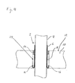
- FIG. 4 shows a further simplified sectional view of a tube 4, which is protected by means of a fire protection sleeve 6 and is guided by an existing in a ceiling 10 opening 2.
- the tabs 14 of the fire sleeve 6 have splayed in the opening 2 and form a pocket 16.
- a backfill material 24 is filled into the annular gap 8, in the exemplary embodiment shown it is mineral wool.
- a Sealant 26 sealed In the area of the surface 12 of the ceiling 10 of the opening 2 is also with a Sealant 26 sealed. This may preferably be a self-leveling sealant such as flowable mortar or gypsum.
- the fire protection collar 6 may be provided on at least one of its two flat sides with an additional compressible layer, e.g. made of sponge rubber, be provided.
- an additional compressible layer e.g. made of sponge rubber
- the fire protection sleeve 6 allows easy installation from the top 12 of the ceiling 10 ago. This allows a quick and inexpensive installation.
- the combination of lost formwork and fire protection sleeve 6 can be dispensed with an additional formwork, which allows a very economical installation. Due to the concentrated positioning of the fire protection cuff contained in the fire protection 6 a reliable and secure foreclosure can be ensured in particular at the bottom of the opening 2.
- the fire protection sleeve 6 according to the features mentioned can be provided as an endless roll material and therefore be used flexibly for different tubes 4 of different diameters. In addition, the insulation of the side facing away from the fire is possible with sufficient roll width S of the fire sleeve 6 for metal pipes or pipe cables in one operation.
Landscapes
- Engineering & Computer Science (AREA)
- Architecture (AREA)
- Structural Engineering (AREA)
- Civil Engineering (AREA)
- General Engineering & Computer Science (AREA)
- Physics & Mathematics (AREA)
- Electromagnetism (AREA)
- Mechanical Engineering (AREA)
- Health & Medical Sciences (AREA)
- Public Health (AREA)
- Business, Economics & Management (AREA)
- Emergency Management (AREA)
- Building Environments (AREA)
Applications Claiming Priority (1)
| Application Number | Priority Date | Filing Date | Title |
|---|---|---|---|
| DE102011082833 | 2011-09-16 |
Publications (2)
| Publication Number | Publication Date |
|---|---|
| EP2570708A2 true EP2570708A2 (fr) | 2013-03-20 |
| EP2570708A3 EP2570708A3 (fr) | 2013-10-09 |
Family
ID=46963416
Family Applications (1)
| Application Number | Title | Priority Date | Filing Date |
|---|---|---|---|
| EP12181471.9A Withdrawn EP2570708A3 (fr) | 2011-09-16 | 2012-08-23 | Manchette pare-feu, utilisation de cette manchette, procédé d'installation d'une manchette pare-feu et traversée de plafond |
Country Status (4)
| Country | Link |
|---|---|
| US (1) | US9151042B2 (fr) |
| EP (1) | EP2570708A3 (fr) |
| AU (1) | AU2012216337A1 (fr) |
| CA (1) | CA2786194C (fr) |
Cited By (3)
| Publication number | Priority date | Publication date | Assignee | Title |
|---|---|---|---|---|
| EP3032667A1 (fr) * | 2014-12-11 | 2016-06-15 | Roxtec AB | Prise pour câble unique |
| EP3051194A1 (fr) * | 2015-01-28 | 2016-08-03 | Svt Brandschutz Vertriebsgesellschaft mbH | Systeme pare-feu de passage d'elements d'installation allonges tels que tubes, conduites et similaires a travers un mur ou un plafond |
| EP3670986A1 (fr) * | 2018-12-17 | 2020-06-24 | Hauff-Technik GmbH & Co. KG | Montage d'une conduite dans une ouverture d'un élément mural ou au sol |
Families Citing this family (25)
| Publication number | Priority date | Publication date | Assignee | Title |
|---|---|---|---|---|
| US10563399B2 (en) | 2007-08-06 | 2020-02-18 | California Expanded Metal Products Company | Two-piece track system |
| US8555566B2 (en) | 2007-08-06 | 2013-10-15 | California Expanded Metal Products Company | Two-piece track system |
| US8087205B2 (en) | 2007-08-22 | 2012-01-03 | California Expanded Metal Products Company | Fire-rated wall construction product |
| US10619347B2 (en) | 2007-08-22 | 2020-04-14 | California Expanded Metal Products Company | Fire-rated wall and ceiling system |
| US8671632B2 (en) | 2009-09-21 | 2014-03-18 | California Expanded Metal Products Company | Wall gap fire block device, system and method |
| US10184246B2 (en) | 2010-04-08 | 2019-01-22 | California Expanded Metal Products Company | Fire-rated wall construction product |
| US10077550B2 (en) * | 2012-01-20 | 2018-09-18 | California Expanded Metal Products Company | Fire-rated joint system |
| DE102013200546A1 (de) * | 2013-01-16 | 2014-07-17 | Hilti Aktiengesellschaft | Akkumulator für eine Handwerkzeugmaschine und Verfahren zum Herstellen eines Akkumulators für eine Handwerkzeugmaschine |
| JP6153781B2 (ja) * | 2013-06-20 | 2017-06-28 | 積水化学工業株式会社 | 排水竪管の接続構造 |
| US10000923B2 (en) * | 2015-01-16 | 2018-06-19 | California Expanded Metal Products Company | Fire blocking reveal |
| CN107466243B (zh) * | 2015-04-17 | 2021-06-04 | 3M创新有限公司 | 穿透阻火系统 |
| US10323856B2 (en) | 2015-05-22 | 2019-06-18 | Superposed Associates Llc | Passive ductwork intumescent fire damper |
| EP3144438A1 (fr) * | 2015-09-17 | 2017-03-22 | HILTI Aktiengesellschaft | Composant de façade, construction et procede de montage du bloc façade |
| US10363443B2 (en) | 2016-06-30 | 2019-07-30 | Superposed Associates Llc | Passive ductwork intumescent fire damper |
| US10700502B2 (en) * | 2016-11-02 | 2020-06-30 | RPH Intellectual Holdings, LLC | Wall penetration panel |
| US10082450B2 (en) | 2017-01-05 | 2018-09-25 | Hilti Aktiengesellschaft | System, method, and apparatus for monitoring characteristics of a fire, smoke, thermal or water barrier device |
| US10753084B2 (en) | 2018-03-15 | 2020-08-25 | California Expanded Metal Products Company | Fire-rated joint component and wall assembly |
| US10689842B2 (en) | 2018-03-15 | 2020-06-23 | California Expanded Metal Products Company | Multi-layer fire-rated joint component |
| CA3041494C (fr) | 2018-04-30 | 2022-07-05 | California Expanded Metal Products Company | Bouchon a cannelures coupe-feu fixe mecaniquement |
| CA3052184C (fr) | 2018-08-16 | 2022-11-29 | California Expanded Metal Products Company | Composants de blocage d`incendie ou de bruit et systemes muraux munis de composants de blocage d`incendie ou de bruit |
| US11524194B2 (en) | 2018-11-20 | 2022-12-13 | Alvin Crosson | Method and apparatus for fire prevention in openings in demising wall |
| US10914065B2 (en) | 2019-01-24 | 2021-02-09 | California Expanded Metal Products Company | Wall joint or sound block component and wall assemblies |
| US11268274B2 (en) | 2019-03-04 | 2022-03-08 | California Expanded Metal Products Company | Two-piece deflection drift angle |
| JP7402625B2 (ja) * | 2019-07-12 | 2023-12-21 | ダイダン株式会社 | 穴埋め材支持具及び穴埋め材充填方法 |
| US11920343B2 (en) | 2019-12-02 | 2024-03-05 | Cemco, Llc | Fire-rated wall joint component and related assemblies |
Citations (7)
| Publication number | Priority date | Publication date | Assignee | Title |
|---|---|---|---|---|
| GB755551A (en) | 1953-05-13 | 1956-08-22 | Dow Chemical Co | Fire retardant coating composition |
| US3562197A (en) | 1963-08-13 | 1971-02-09 | Monsanto Co | Water-insoluble ammonium polyphosphates as fire-retardant additives |
| US3969291A (en) | 1974-03-06 | 1976-07-13 | Sumitomo Chemical Company, Limited | Intumescent fire-retardant coating compositions containing amide-polyphosphates |
| GB2007689A (en) | 1977-10-10 | 1979-05-23 | Montedison Spa | Intumescent paints |
| US4442157A (en) | 1978-02-23 | 1984-04-10 | Basf Aktiengesellschaft | Fireproofing composition and door rabbet coated therewith |
| EP0138546A2 (fr) | 1983-10-07 | 1985-04-24 | Dixon International Limited | Composition intumescente |
| EP0139401A1 (fr) | 1983-08-23 | 1985-05-02 | Dixon International Limited | Matériau intumescent |
Family Cites Families (47)
| Publication number | Priority date | Publication date | Assignee | Title |
|---|---|---|---|---|
| US2342458A (en) * | 1941-01-21 | 1944-02-22 | Davies Wayne | Packing spacer |
| US2434484A (en) * | 1945-02-09 | 1948-01-13 | Garlock Packing Co | Oil seal |
| US3476411A (en) * | 1968-05-29 | 1969-11-04 | Heil Quaker Corp | Panel coupling having means for preventing axial and rotational movement |
| US3995102A (en) * | 1974-01-25 | 1976-11-30 | Raceway Components, Inc. | Insert device for cables |
| US4199157A (en) * | 1978-06-08 | 1980-04-22 | Press-Seal Gasket Corporation | Two part sleeve gasket |
| US4215868A (en) * | 1978-08-23 | 1980-08-05 | Press Seal Gasket Corporation | Gasket apparatus and method |
| US4323724A (en) * | 1980-05-01 | 1982-04-06 | Shine William P | Unitary insertable self-anchoring poke-thru wiring device |
| US4364210A (en) * | 1980-05-29 | 1982-12-21 | Minnesota Mining And Manufacturing Company | Fire barrier device |
| IE822972L (en) * | 1982-12-23 | 1984-06-23 | Attwell Ronald Leslie | Fire stop flue collar |
| US4559745A (en) * | 1983-12-22 | 1985-12-24 | Fire Research Pty. Limited | Devices for the fire stopping of plastics pipes |
| US4888925A (en) * | 1987-11-03 | 1989-12-26 | Harbeke Gerold J | Fire-retardant fluid coupling assembly and method |
| US4848043A (en) * | 1988-09-14 | 1989-07-18 | Harbeke Gerold J | Under floor fire stop coupling and method |
| US4991858A (en) * | 1989-03-07 | 1991-02-12 | Hamilton Kent Manufacturing, Inc. | Connector seal |
| US4951442A (en) * | 1989-08-31 | 1990-08-28 | Msp Products, Inc. | Method for constructing fire-stop collar assembly |
| US5058341A (en) * | 1989-08-31 | 1991-10-22 | Msp Products, Inc. | Method for constructing fire-stop collar assembly and apparatus thereof |
| US5103609A (en) * | 1990-11-15 | 1992-04-14 | Minnesota Mining & Manufacturing Company | Intumescable fire stop device |
| US5155957A (en) * | 1991-01-14 | 1992-10-20 | National Improvement Company, Inc. | Fire safety device |
| US5326609A (en) * | 1992-06-25 | 1994-07-05 | Metalines | Expansion joint fire barrier |
| US5498466A (en) * | 1993-03-12 | 1996-03-12 | International Protective Coatings Corp. | Intumescent composite |
| DE4325757A1 (de) * | 1993-07-31 | 1995-02-02 | Gruenau Gmbh Chem Fab | Rohrschott mit einem um ein Rohr biegbaren Blechmantel |
| US5953872A (en) * | 1993-08-13 | 1999-09-21 | Macmillian; George S. | Fire barrier assembly |
| CA2111545C (fr) * | 1993-12-15 | 2007-04-03 | Michael P. Sakno | Conduit coupe-feu non rigide impermeable et intumescent |
| DE4411220A1 (de) * | 1994-03-31 | 1995-10-05 | Hilti Ag | Rohrmanschette |
| US5765332A (en) * | 1995-02-21 | 1998-06-16 | Minnesota Mining And Manufacturing Company | Fire barrier protected dynamic joint |
| US5806139A (en) * | 1996-04-24 | 1998-09-15 | Hi-Lex Corporation | Grommet assembly |
| JPH1089545A (ja) * | 1996-09-18 | 1998-04-10 | Toosetsu Kk | 防火区画貫通部材 |
| US6029412A (en) * | 1997-02-12 | 2000-02-29 | Rectorseal Corp. | Intumescent interlocking collar |
| US5887395A (en) * | 1997-09-19 | 1999-03-30 | International Protective Coatings Corp. | Firestop sleeve |
| US5885912A (en) * | 1997-10-08 | 1999-03-23 | Bumbarger; Thomas H. | Protective multi-layered liquid retaining composite |
| US5887396A (en) * | 1998-05-13 | 1999-03-30 | Minnesota Mining And Manufacturing Company | Intumescable fire stop device having quick fasteners |
| DE19852120C2 (de) * | 1998-08-19 | 2002-12-12 | Friatec Ag | Intumeszierende Brandschutzvorrichtung zum Abschotten von durch Wände oder Decken durchgeführten Rohren |
| EP1124890A1 (fr) * | 1998-10-22 | 2001-08-22 | Parker-Hannifin Corporation | Composition auto-adhesive retardatrice de flammes et intumescente pour applications de blindage electromagnetique |
| AUPQ024099A0 (en) * | 1999-05-07 | 1999-06-03 | Promat Fyreguard Pty Ltd | Service shut off device |
| US6176052B1 (en) * | 1999-05-21 | 2001-01-23 | Tosetz Co., Ltd. | Fire retarding division penetrating member |
| NL1012759C2 (nl) * | 1999-08-02 | 2001-02-05 | Beele Eng Bv | Afdichtsamenstel en afdichtmanchet hiervoor. |
| DE19960485A1 (de) * | 1999-12-15 | 2001-06-21 | Hilti Ag | Brandschutzmanschette für Rohre, Kabel u. dgl. |
| US6405502B1 (en) * | 2000-05-18 | 2002-06-18 | Kenneth R. Cornwall | Firestop assembly comprising intumescent material within a metal extension mounted on the inner surface of a plastic coupling |
| US20030167712A1 (en) * | 2000-08-23 | 2003-09-11 | Paul Robertson | Fire barrie devices |
| EP1362961B1 (fr) * | 2002-04-29 | 2005-11-09 | Dallmer GmbH & Co. KG | Elément de construction pour la protection coupe-feu d' un dispositif d' écoulement et dispositif d'écoulement comprenant un tel élement |
| EP1396675A1 (fr) * | 2002-09-05 | 2004-03-10 | Tosetz Co. Ltd. | Appareil de protection contre le feu |
| US7568314B2 (en) * | 2004-08-05 | 2009-08-04 | Pacc Systems I.P., Llc | Flashing kit for wall penetrations |
| DE102004043970B4 (de) * | 2004-09-11 | 2007-12-13 | Hilti Ag | Durchführungsvorrichtung |
| GB0800765D0 (en) * | 2008-01-16 | 2008-02-27 | Beele Eng Bv | Fire-stop system for placement in a conduit through which a thermally weakenable pipe extends, method for placing the system and conduit provided |
| US8024900B2 (en) * | 2008-07-30 | 2011-09-27 | 3M Innovative Properties Company | Pass-through firestop apparatus and methods |
| AU2009245873A1 (en) * | 2008-12-10 | 2010-07-01 | Ig6 Pty Ltd | Fire containment devices and components therefor |
| NL2004318C2 (en) * | 2010-03-01 | 2011-09-05 | Walraven Holding Bv J Van | FIRESTOP COLLAR. |
| DE102011004575A1 (de) * | 2011-02-23 | 2012-08-23 | Hilti Aktiengesellschaft | Leitungselementdurchführung |
-
2012
- 2012-08-16 CA CA2786194A patent/CA2786194C/fr active Active
- 2012-08-21 AU AU2012216337A patent/AU2012216337A1/en not_active Abandoned
- 2012-08-23 EP EP12181471.9A patent/EP2570708A3/fr not_active Withdrawn
- 2012-09-14 US US13/618,386 patent/US9151042B2/en active Active
Patent Citations (7)
| Publication number | Priority date | Publication date | Assignee | Title |
|---|---|---|---|---|
| GB755551A (en) | 1953-05-13 | 1956-08-22 | Dow Chemical Co | Fire retardant coating composition |
| US3562197A (en) | 1963-08-13 | 1971-02-09 | Monsanto Co | Water-insoluble ammonium polyphosphates as fire-retardant additives |
| US3969291A (en) | 1974-03-06 | 1976-07-13 | Sumitomo Chemical Company, Limited | Intumescent fire-retardant coating compositions containing amide-polyphosphates |
| GB2007689A (en) | 1977-10-10 | 1979-05-23 | Montedison Spa | Intumescent paints |
| US4442157A (en) | 1978-02-23 | 1984-04-10 | Basf Aktiengesellschaft | Fireproofing composition and door rabbet coated therewith |
| EP0139401A1 (fr) | 1983-08-23 | 1985-05-02 | Dixon International Limited | Matériau intumescent |
| EP0138546A2 (fr) | 1983-10-07 | 1985-04-24 | Dixon International Limited | Composition intumescente |
Cited By (3)
| Publication number | Priority date | Publication date | Assignee | Title |
|---|---|---|---|---|
| EP3032667A1 (fr) * | 2014-12-11 | 2016-06-15 | Roxtec AB | Prise pour câble unique |
| EP3051194A1 (fr) * | 2015-01-28 | 2016-08-03 | Svt Brandschutz Vertriebsgesellschaft mbH | Systeme pare-feu de passage d'elements d'installation allonges tels que tubes, conduites et similaires a travers un mur ou un plafond |
| EP3670986A1 (fr) * | 2018-12-17 | 2020-06-24 | Hauff-Technik GmbH & Co. KG | Montage d'une conduite dans une ouverture d'un élément mural ou au sol |
Also Published As
| Publication number | Publication date |
|---|---|
| CA2786194A1 (fr) | 2013-03-16 |
| US9151042B2 (en) | 2015-10-06 |
| EP2570708A3 (fr) | 2013-10-09 |
| US20130091789A1 (en) | 2013-04-18 |
| AU2012216337A1 (en) | 2013-04-04 |
| CA2786194C (fr) | 2019-01-15 |
Similar Documents
| Publication | Publication Date | Title |
|---|---|---|
| EP2570708A2 (fr) | Manchette pare-feu, utilisation de cette manchette, procédé d'installation d'une manchette pare-feu et traversée de plafond | |
| EP2570157B1 (fr) | Elément ignifuge | |
| EP3289265B1 (fr) | Manchette coupe-feu | |
| DE102005054375A1 (de) | Schwer brennbares oder nicht brennbares Schaumstoffprofil zur brandschützenden Abdichtung von Bauöffnungen | |
| EP3060612A1 (fr) | Corps élastomère pour amortissement de vibrations | |
| EP3132002B1 (fr) | Composition ignifuge et son utilisation | |
| DE102011089531A1 (de) | Brandschutzmanschette | |
| EP3643365A1 (fr) | Élement ignifuge destiné à l'étanchéité des ouvertures de passage dans des composants | |
| WO2018153662A1 (fr) | Élément coupe-feu | |
| EP2061126B1 (fr) | Passage de câble ignifuge | |
| DE19725301C2 (de) | Brandschutzmaterial für Bauzwecke sowie dessen Herstellung und Verwendung | |
| EP3289266B1 (fr) | Manchette coupe-feu | |
| EP3289267B1 (fr) | Manchette coupe-feu | |
| EP3870315A1 (fr) | Élément coupe-feu pour rendre étanches des ouvertures de passage dans des éléments de construction | |
| EP3184709A1 (fr) | Procédé de fabrication d'un élément isolant ignifugé, élément isolant et utilisation d'un élément isolant | |
| DE3602118C2 (de) | Anordnung zur im Brandfall wirksamen Abdichtung von Öffnungen in Bauteilen | |
| EP3272965B1 (fr) | Dispositif coupe-feu pour structures de faux-planchers | |
| EP2514488B1 (fr) | Cloison souple comprimable, son procédé de fabrication et d'utilisation | |
| EP3680096A1 (fr) | Élément de surface résistant au feu | |
| DE202024104007U1 (de) | Brandschutzaufbau zum Schutz eines in einem Brandabschnitt freihängenden Kabels, einer Leitung oder eines Rohres und entsprechende Verwendungen |
Legal Events
| Date | Code | Title | Description |
|---|---|---|---|
| PUAI | Public reference made under article 153(3) epc to a published international application that has entered the european phase |
Free format text: ORIGINAL CODE: 0009012 |
|
| AK | Designated contracting states |
Kind code of ref document: A2 Designated state(s): AL AT BE BG CH CY CZ DE DK EE ES FI FR GB GR HR HU IE IS IT LI LT LU LV MC MK MT NL NO PL PT RO RS SE SI SK SM TR |
|
| AX | Request for extension of the european patent |
Extension state: BA ME |
|
| PUAL | Search report despatched |
Free format text: ORIGINAL CODE: 0009013 |
|
| AK | Designated contracting states |
Kind code of ref document: A3 Designated state(s): AL AT BE BG CH CY CZ DE DK EE ES FI FR GB GR HR HU IE IS IT LI LT LU LV MC MK MT NL NO PL PT RO RS SE SI SK SM TR |
|
| AX | Request for extension of the european patent |
Extension state: BA ME |
|
| RIC1 | Information provided on ipc code assigned before grant |
Ipc: E04B 1/94 20060101ALI20130830BHEP Ipc: E04B 9/00 20060101ALI20130830BHEP Ipc: F16L 5/04 20060101AFI20130830BHEP |
|
| 17P | Request for examination filed |
Effective date: 20140409 |
|
| RBV | Designated contracting states (corrected) |
Designated state(s): AL AT BE BG CH CY CZ DE DK EE ES FI FR GB GR HR HU IE IS IT LI LT LU LV MC MK MT NL NO PL PT RO RS SE SI SK SM TR |
|
| 17Q | First examination report despatched |
Effective date: 20151201 |
|
| STAA | Information on the status of an ep patent application or granted ep patent |
Free format text: STATUS: THE APPLICATION IS DEEMED TO BE WITHDRAWN |
|
| 18D | Application deemed to be withdrawn |
Effective date: 20180605 |