EP2570638A2 - Coordinated emissions control system of a diesel engine with selective catalytic reduction - Google Patents
Coordinated emissions control system of a diesel engine with selective catalytic reduction Download PDFInfo
- Publication number
- EP2570638A2 EP2570638A2 EP12184343A EP12184343A EP2570638A2 EP 2570638 A2 EP2570638 A2 EP 2570638A2 EP 12184343 A EP12184343 A EP 12184343A EP 12184343 A EP12184343 A EP 12184343A EP 2570638 A2 EP2570638 A2 EP 2570638A2
- Authority
- EP
- European Patent Office
- Prior art keywords
- exhaust
- engine
- selective catalytic
- controller
- catalytic reduction
- Prior art date
- Legal status (The legal status is an assumption and is not a legal conclusion. Google has not performed a legal analysis and makes no representation as to the accuracy of the status listed.)
- Pending
Links
Images


Classifications
-
- F—MECHANICAL ENGINEERING; LIGHTING; HEATING; WEAPONS; BLASTING
- F01—MACHINES OR ENGINES IN GENERAL; ENGINE PLANTS IN GENERAL; STEAM ENGINES
- F01N—GAS-FLOW SILENCERS OR EXHAUST APPARATUS FOR MACHINES OR ENGINES IN GENERAL; GAS-FLOW SILENCERS OR EXHAUST APPARATUS FOR INTERNAL COMBUSTION ENGINES
- F01N3/00—Exhaust or silencing apparatus having means for purifying, rendering innocuous, or otherwise treating exhaust
- F01N3/08—Exhaust or silencing apparatus having means for purifying, rendering innocuous, or otherwise treating exhaust for rendering innocuous
- F01N3/10—Exhaust or silencing apparatus having means for purifying, rendering innocuous, or otherwise treating exhaust for rendering innocuous by thermal or catalytic conversion of noxious components of exhaust
- F01N3/18—Exhaust or silencing apparatus having means for purifying, rendering innocuous, or otherwise treating exhaust for rendering innocuous by thermal or catalytic conversion of noxious components of exhaust characterised by methods of operation; Control
- F01N3/20—Exhaust or silencing apparatus having means for purifying, rendering innocuous, or otherwise treating exhaust for rendering innocuous by thermal or catalytic conversion of noxious components of exhaust characterised by methods of operation; Control specially adapted for catalytic conversion ; Methods of operation or control of catalytic converters
- F01N3/2066—Selective catalytic reduction [SCR]
- F01N3/208—Control of selective catalytic reduction [SCR], e.g. dosing of reducing agent
-
- F—MECHANICAL ENGINEERING; LIGHTING; HEATING; WEAPONS; BLASTING
- F01—MACHINES OR ENGINES IN GENERAL; ENGINE PLANTS IN GENERAL; STEAM ENGINES
- F01N—GAS-FLOW SILENCERS OR EXHAUST APPARATUS FOR MACHINES OR ENGINES IN GENERAL; GAS-FLOW SILENCERS OR EXHAUST APPARATUS FOR INTERNAL COMBUSTION ENGINES
- F01N9/00—Electrical control of exhaust gas treating apparatus
- F01N9/005—Electrical control of exhaust gas treating apparatus using models instead of sensors to determine operating characteristics of exhaust systems, e.g. calculating catalyst temperature instead of measuring it directly
-
- F—MECHANICAL ENGINEERING; LIGHTING; HEATING; WEAPONS; BLASTING
- F02—COMBUSTION ENGINES; HOT-GAS OR COMBUSTION-PRODUCT ENGINE PLANTS
- F02D—CONTROLLING COMBUSTION ENGINES
- F02D41/00—Electrical control of supply of combustible mixture or its constituents
- F02D41/02—Circuit arrangements for generating control signals
- F02D41/021—Introducing corrections for particular conditions exterior to the engine
- F02D41/0235—Introducing corrections for particular conditions exterior to the engine in relation with the state of the exhaust gas treating apparatus
-
- F—MECHANICAL ENGINEERING; LIGHTING; HEATING; WEAPONS; BLASTING
- F02—COMBUSTION ENGINES; HOT-GAS OR COMBUSTION-PRODUCT ENGINE PLANTS
- F02D—CONTROLLING COMBUSTION ENGINES
- F02D41/00—Electrical control of supply of combustible mixture or its constituents
- F02D41/02—Circuit arrangements for generating control signals
- F02D41/14—Introducing closed-loop corrections
- F02D41/1401—Introducing closed-loop corrections characterised by the control or regulation method
-
- F—MECHANICAL ENGINEERING; LIGHTING; HEATING; WEAPONS; BLASTING
- F02—COMBUSTION ENGINES; HOT-GAS OR COMBUSTION-PRODUCT ENGINE PLANTS
- F02D—CONTROLLING COMBUSTION ENGINES
- F02D41/00—Electrical control of supply of combustible mixture or its constituents
- F02D41/24—Electrical control of supply of combustible mixture or its constituents characterised by the use of digital means
- F02D41/26—Electrical control of supply of combustible mixture or its constituents characterised by the use of digital means using computer, e.g. microprocessor
- F02D41/266—Electrical control of supply of combustible mixture or its constituents characterised by the use of digital means using computer, e.g. microprocessor the computer being backed-up or assisted by another circuit, e.g. analogue
-
- F—MECHANICAL ENGINEERING; LIGHTING; HEATING; WEAPONS; BLASTING
- F01—MACHINES OR ENGINES IN GENERAL; ENGINE PLANTS IN GENERAL; STEAM ENGINES
- F01N—GAS-FLOW SILENCERS OR EXHAUST APPARATUS FOR MACHINES OR ENGINES IN GENERAL; GAS-FLOW SILENCERS OR EXHAUST APPARATUS FOR INTERNAL COMBUSTION ENGINES
- F01N2610/00—Adding substances to exhaust gases
- F01N2610/02—Adding substances to exhaust gases the substance being ammonia or urea
-
- F—MECHANICAL ENGINEERING; LIGHTING; HEATING; WEAPONS; BLASTING
- F01—MACHINES OR ENGINES IN GENERAL; ENGINE PLANTS IN GENERAL; STEAM ENGINES
- F01N—GAS-FLOW SILENCERS OR EXHAUST APPARATUS FOR MACHINES OR ENGINES IN GENERAL; GAS-FLOW SILENCERS OR EXHAUST APPARATUS FOR INTERNAL COMBUSTION ENGINES
- F01N2900/00—Details of electrical control or of the monitoring of the exhaust gas treating apparatus
- F01N2900/04—Methods of control or diagnosing
-
- F—MECHANICAL ENGINEERING; LIGHTING; HEATING; WEAPONS; BLASTING
- F01—MACHINES OR ENGINES IN GENERAL; ENGINE PLANTS IN GENERAL; STEAM ENGINES
- F01N—GAS-FLOW SILENCERS OR EXHAUST APPARATUS FOR MACHINES OR ENGINES IN GENERAL; GAS-FLOW SILENCERS OR EXHAUST APPARATUS FOR INTERNAL COMBUSTION ENGINES
- F01N2900/00—Details of electrical control or of the monitoring of the exhaust gas treating apparatus
- F01N2900/06—Parameters used for exhaust control or diagnosing
- F01N2900/14—Parameters used for exhaust control or diagnosing said parameters being related to the exhaust gas
- F01N2900/1402—Exhaust gas composition
-
- F—MECHANICAL ENGINEERING; LIGHTING; HEATING; WEAPONS; BLASTING
- F02—COMBUSTION ENGINES; HOT-GAS OR COMBUSTION-PRODUCT ENGINE PLANTS
- F02D—CONTROLLING COMBUSTION ENGINES
- F02D41/00—Electrical control of supply of combustible mixture or its constituents
- F02D41/02—Circuit arrangements for generating control signals
- F02D41/14—Introducing closed-loop corrections
- F02D41/1401—Introducing closed-loop corrections characterised by the control or regulation method
- F02D2041/1412—Introducing closed-loop corrections characterised by the control or regulation method using a predictive controller
-
- F—MECHANICAL ENGINEERING; LIGHTING; HEATING; WEAPONS; BLASTING
- F02—COMBUSTION ENGINES; HOT-GAS OR COMBUSTION-PRODUCT ENGINE PLANTS
- F02D—CONTROLLING COMBUSTION ENGINES
- F02D41/00—Electrical control of supply of combustible mixture or its constituents
- F02D41/02—Circuit arrangements for generating control signals
- F02D41/14—Introducing closed-loop corrections
- F02D41/1401—Introducing closed-loop corrections characterised by the control or regulation method
- F02D2041/1433—Introducing closed-loop corrections characterised by the control or regulation method using a model or simulation of the system
-
- F—MECHANICAL ENGINEERING; LIGHTING; HEATING; WEAPONS; BLASTING
- F02—COMBUSTION ENGINES; HOT-GAS OR COMBUSTION-PRODUCT ENGINE PLANTS
- F02D—CONTROLLING COMBUSTION ENGINES
- F02D2250/00—Engine control related to specific problems or objectives
- F02D2250/36—Control for minimising NOx emissions
-
- Y—GENERAL TAGGING OF NEW TECHNOLOGICAL DEVELOPMENTS; GENERAL TAGGING OF CROSS-SECTIONAL TECHNOLOGIES SPANNING OVER SEVERAL SECTIONS OF THE IPC; TECHNICAL SUBJECTS COVERED BY FORMER USPC CROSS-REFERENCE ART COLLECTIONS [XRACs] AND DIGESTS
- Y02—TECHNOLOGIES OR APPLICATIONS FOR MITIGATION OR ADAPTATION AGAINST CLIMATE CHANGE
- Y02T—CLIMATE CHANGE MITIGATION TECHNOLOGIES RELATED TO TRANSPORTATION
- Y02T10/00—Road transport of goods or passengers
- Y02T10/10—Internal combustion engine [ICE] based vehicles
- Y02T10/12—Improving ICE efficiencies
-
- Y—GENERAL TAGGING OF NEW TECHNOLOGICAL DEVELOPMENTS; GENERAL TAGGING OF CROSS-SECTIONAL TECHNOLOGIES SPANNING OVER SEVERAL SECTIONS OF THE IPC; TECHNICAL SUBJECTS COVERED BY FORMER USPC CROSS-REFERENCE ART COLLECTIONS [XRACs] AND DIGESTS
- Y02—TECHNOLOGIES OR APPLICATIONS FOR MITIGATION OR ADAPTATION AGAINST CLIMATE CHANGE
- Y02T—CLIMATE CHANGE MITIGATION TECHNOLOGIES RELATED TO TRANSPORTATION
- Y02T10/00—Road transport of goods or passengers
- Y02T10/10—Internal combustion engine [ICE] based vehicles
- Y02T10/40—Engine management systems
Definitions
- the present disclosure pertains to environmentally harmful emissions and particularly to an approach to reduce such emissions from internal combustion engines.
- the disclosure reveals a system for reducing environmentally harmful emissions from an internal combustion engine.
- the system may incorporate an exhaust after-treatment device.
- the exhaust after-treatment device may use selective catalytic reduction to remove certain emissions from the exhaust of the engine.
- Urea solution may be inserted into the exhaust emissions, which is decomposed to ammonia to become a reduction agent for reduction of NOx in the emissions.
- the engine may be managed by a controller and the exhaust after-treatment device may be managed by another controller. These controllers may be cascaded, or be managed by a third controller that provides hierarchical or central coordinated control of engine performance and emissions reduction.
- the engine and the exhaust after-treatment device may be modeled to aid in designing and building a system for coordinated control of an actual engine and a selective catalytic reduction after-treatment device.
- the controllers may be predictive model controllers.
- SCR selective catalytic reduction
- control strategies need to be coordinated in order to achieve the maximum achievable performance -- in terms of NOx emissions and vehicle fuel economy.
- the present approach may coordinate the control of the engine and SCR device. Coordinated control of these two subcomponents may lead to very much reduced NOx emissions to meet strict clean air regulations and also improved vehicle fuel efficiency.
- an engine control system may simply and generally always try to reduce the engine-out NOx as much as possible. This may often be done by a massive exhaust gas recirculation which is not necessarily optimal for soot emissions and fuel efficiency. It may often be thought, from an overall optimality point of view, that the engine control system rely on the aftertreatment mechanism to reduce NOx emissions. Instead, the engine control system should control the aftertreatment temperature to maximize its efficiency. This may be achieved virtually only by coordinated control.
- the present approach may utilize modeling and control technology.
- models of the engine and after-treatment subsystems may be created.
- the models of the engine and exhaust after-treatment subsystems may track actual engine and exhaust after-treatment subsystems. From these models one or more multivariable controllers may be synthesized.
- a multi-variable controller may address the inherent interactions of an overall coordinated engine-SCR control system.
- the present description may treat the models of the engine and exhaust after-treatment subsystems as actual subsystems.
- FIG. 1 is a diagram of a basic engine plant model system 10.
- Input 12 (w eng ) may incorporate detected engine speed, fueling rate, ambient conditions, such as temperature and air pressure, and so on.
- Input 13 (u eng ) may incorporate signals to actuators on the engine (e.g., variable geometry turbine (VGT), exhaust gas recirculation (EGR), throttles, fuel injection specifications, variable valve actuation (VVA), and so on).
- VVT variable geometry turbine
- EGR exhaust gas recirculation
- VVA variable valve actuation
- VVA variable valve actuation
- G eng representing an engine plant model, such as a diesel engine with a turbocharger.
- An output 14 may be based on SFC (specific fuel consumption, for instance, in grams per kilowatt hour) of the engine.
- An output 15 may indicate a PM (particulate matter) output of the engine and output 17 may indicate a NOx eng (i.e., nitrogen oxides) output of the engine. NOx may be measured in parts per million.
- FIG. 2 is a diagram of a basic engine arrangement 18 with control but no SCR.
- a feedback 19 (y eng ) (engine sensors) from G eng 11 to a K eng block 21 which may represent an embedded computer.
- y eng 19 may incorporate signals from sensors for MAP, EGR flow, temperatures, NOx emissions, and so on.
- K eng controller 21 may incorporate one or more control algorithms.
- a signal 19 may represent the on-engine measurements.
- "y eng " may be regarded as engine sensors.
- a control goal may be to control the various actuators to achieve engine specific goals such as tracking desired boost pressures, fresh and/or mass air flow, EGR flow, and so forth, and indirectly be responsible for providing trade offs among SFC, PM and NOx, and other items. Often a control goal may be to minimize SFC such that legal constraints on PM and NOx are satisfied.
- U eng 13 (engine actuators) may incorporate actuator signals from K eng controller 21 to G eng block 11.
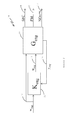
- FIG. 3 is a diagram of a combined engine and SCR plant system 23.
- an SCR after-treatment device 24 may change the NOx component of the engine outputs by adding an ammonia component (NH3).
- NH3 ammonia component
- the performance may in part be defined by SFC 14 and PM 15 from the G eng block 11.
- a signal 17 representing or indicating Nox eng , T exh (exhaust temperature) and m exh (exhaust mass) may proceed from the G eng block 11 to an SCR after-treatment (G scr ) device 24.
- the T exh may be determined before an entry of the exhaust to device 24.
- System 23 may provide a u urea input signal 25 to G scr device block 24.
- "u uera” may be regarded as a urea solution dosing actuator.
- Block 24 may have an output 26 of NOx scr and an output 27 of NH3 scr .
- Outputs 26 and 27 are the items of the system that may need to meet legal requirements relating to exhaust NOx emissions.
- a time constant may be associated with the engine in block 11 and with the SCR device in block 24.
- the time constant of block 11 may be an amount of time (e.g., about 1-2 seconds) that is needed for changed inputs to block 11 to result in a certain amount (e.g., 63 percent) of stabilization of the response of the system to the inputs.
- the time constant of block 24 may be an amount of time (e.g., about 20-30 seconds) that the after-treatment device needs because of a temperature change caused by a change of inputs resulting in a change of exhaust.
- a catalyst may be a part of the device (usually contained in a wash coat). What is injected to the exhaust gas may be a urea solution which is decomposed to ammonia and the ammonia is used as reduction agent for various chemical reactions (e.g., NOx reduction). Ammonia is adsorbed on the catalyst (e.g., a catalyst of a platinum-zeolite type)
- FIG 4 is a diagram of an uncoordinated engine and SCR control system 28, having portions of system 18 of Figure 2 and system 24 of Figure 3 , and additionally a K scr block 31 in a feedback loop of G scr block 24 with a y scr signal 29 (SCR sensors) from G scr block 24 or after-treatment mechanism 24 to a K scr or controller block 31 and a u urea signal 25 input from controller block 31 to the G scr block 24 for controlling an amount of urea solution injected into the engine exhaust 17 in the after-treatment mechanism 24.
- y scr may be regarded as SCR sensors. Such SCR sensors may be for upstream NOx (engine-out NOx), downstream NOx (tailpipe-out NOx), downstream NH3, upstream/downstream temperatures, exhaust flow, and the like.
- Techniques for SCR control may have the K scr 31 act on information y scr 29 of the state of the exhaust 17 entering the G scr 24 or SCR device 24.
- the state of the exhaust entering device 24 may be some combination of NOx, T exh and/or m exh .
- a state of the exhaust that is leaving the SCR device 24 may be some combination of NOx and/or NH3.
- the SCR device 24 may decrease the engine out NOx, which could mean that there is extra capability in the engine controller K eng 21 to optimize the other items.
- one may have a tradeoff where there is a making NOx eng higher to achieve a better SFC or vice versa.
- the performance of the SCR device 24 may be governed by the urea solution dosing and also the properties of NOx eng (NOx concentration of exhaust gas), T exh (temperature of exhaust gas), and m exh (mass flow of exhaust gas) which influence the SCR device's states (temperature and NH3 coverage).
- the engine variables in turn may vary as a function of engine speed and fuel, ambient conditions, and engine actuators, which change much faster than a 20-30 second time constant of the G scr or SCR 24.
- the actuators relative to u eng may be responsible for governing engine functions in order to manipulate engine performance factors such as SFC and PM in addition to managing the SCR relevant variables of NOx eng , T exh , and m exh .
- NOx eng , T exh , m exh might be coordinated with a urea solution dosing to enhance the overall performance of the engine-SCR system 28, but one may need to carefully consider what aspects of the control to focus on. That is, one cannot necessarily expect to be able to hold NOx eng , T exh , and m exh at a desired setpoint for a very long time considering the dynamic needs of SCR 24 and the fact that the engine actuators of G eng 11 or engine plant model 11 also have to deliver engine performance.
- FIG. 5 is a diagram of a system 34 with cascaded coordinated control which may be considered.
- Cascading controllers 31 and 21 may be a part of the system's control strategy. Implicit in controller 31 may be a supervisory controller.
- a w eng signal 12 may enter a K scr controller block 31 and a G eng engine block 11.
- a r eng signal 36 may go from the K scr block 31 to the K eng block 21.
- a u eng signal 13 for engine actuators may go from the K eng block 21 to the G eng block 11.
- a signal y eng 19 from engine sensors may have information fed back from the G eng block 11 to the K eng block 21.
- An output SFC signal 14 and a PM signal 15 may be output from the G eng block 11.
- a directly or indirectly measured NOx eng , T exh , m exh signal 17 may go from the G eng block 11 to a G scr block 24.
- the K scr block 31 may provide an output signal u urea 25 signal (actuator) for indicating an amount of urea solution to be injected into the SCR device G scr block 24.
- the G scr block 24 may feed back a y scr signal 29 with SCR sensor information about G scr 24 to the K scr block 31 for modification of setpoints, input parameters, speed, fuel, and so on, of the engine as indicated by w eng 12.
- the SCR device (G scr block 24) may output a NOx scr signal 26 and an NH3 scr signal 27.
- the r eng signal 36 may refer to the setpoints and input parameters for the engine controller (K eng ) 21.
- the SCR controller (K scr ) 31 may use the r eng signal 36 for actuation to assist in the SCR 24 control via the NOx eng , T exh and m exh signal 17.
- K eng block 21 and/or K scr block 31 may each represent a model predictive control (MPC) controller. If one assumes that K scr block 31 represents an MPC controller, then one may put constraints on the r eng signal 36 so that engine control goals, such as, for example, requirements on PM, SFC and NOx eng , are respected.
- the present structure 34 may permit a use of the r eng signal 36 to enhance a slow transient response of the K scr block 31.
- FIG. 6 is a diagram of a hierarchical coordinated control system 38.
- a w eng signal 12 may enter a K block 39 and a G eng block 11.
- a r eng signal 36 may go from the K block 39 to a K eng block 21.
- a u eng signal 13 may go from the K eng block 21 to the G eng block 11.
- a y eng signal 19 may be fed back from the G eng block 11 to the K eng block 21.
- An output of the engine may include SFC 14 and a PM signal 15 as output from the G eng block 11.
- a NOx eng , T exh and m exh signal 17 may go from the G eng block 11 to a G scr block 24.
- An r scr signal 41 may go from the K block 39 to a K scr block 31.
- a u urea signal 25 may go from the K scr block 31 to the G scr block 24.
- Outputs from the SCR device G scr block 24 may include a NOx scr signal 26
- the control strategy for system 38 of Figure 6 may have a hierarchical structure with the controller K scr 31 dedicated to the G scr 24.
- the K block 39 may be a supervisor controller or coordinator which manipulates the setpoints w eng , r eng , r scr and so on for the local controllers K eng 21 and K scr 31, so that the prescribed goals are achieved, i.e., namely, the requirements for NOx scr , NH3 scr , PM, SFC, and so forth.
- K block 39, K eng block 21 and/or K scr block 31 may each represent an MPC controller.
- Model predictive control is a control approach that appears to have been successfully applied in many industrial control applications. MPC appears suitable for applications where it may be necessary dynamically coordinate several actuators to drive several controlled variables. Such systems may be known as multivariable. MPC appears able to include constraints on various signals in a control loop systematically. The ability to handle the constrained multivariable dynamical system in a systematic way may be the key factor which increases popularity of MPC.
- MPC may use a dynamical model of the controlled system to predict future behavior of a controlled technology or process. Based on this prediction and based on defined optimality criteria, MPC may compute an optimal control signal by solving a constrained optimization problem. This optimization problem should be solved at each sampling period to reject the disturbances and to ensure certain degree of robustness.
- An example of such optimization problem is expression (1).
- Uopt arg min J U ⁇ x ⁇ p s . t .
- Uopt is the optimal control signal trajectory
- J(U,x,p) is MPC cost function
- g(U,x,p) represents MPC constraints
- U is the optimization variable
- x may be the internal state of the controlled system
- p may represent various parameters.
- the cost function J(U,x,p) may be a weighted sum of various penalties, for example, a sum of squared 2nd norms of tracking error over the prediction horizon, sum of squared 2nd norms of actuator movements, and so on.
- Constraints g(U,x,p) may include limits for actuators and for various controlled variables over the prediction horizon.
- solvers for a fast MPC may enable an application of MPC technology for relatively fast automotive systems, for example, an engine air path or emissions control as it is briefly described herein.
- Suitable solvers for fast MPC may be based on an on-line solution or explicit solution of a parametric optimization problem (1).
- the solvers for MPC may be standard, directly tailored for MPC or directly tailored for a particular MPC application.
- the on-line solvers may be based on active set (standard formulation, gradient projection, and so forth), interior point, and so on.
- the explicit solution may be based on multi-parametric approach, primal-dual feasibility approach, and so on.
- An uncoordinated MPC control may be illustrated by the control structure shown in Figure 4 (block or system 28).
- One or both controllers 21 and 31 may be implemented as an MPC.
- the objective of engine air path controller K eng 21 is to ensure that the selected controlled variables will follow their setpoints while all given constraints will be satisfied.
- the controlled variables 19 (engine sensors) may be, for example, any combination from the following set: boost pressure, exhaust gas recirculation flow, lambda sensor, exhaust manifold pressure, total engine air flow, turbocharger speed, and so on.
- the engine actuators 13 may be exhaust gas recirculation valve, turbocharger actuator, wastegate valve, throttle valve, start of injection, and so forth.
- the considered constraints may be, for example, upper and lower limits of actuator positions, a limit for lambda sensor, a limit for turbocharger speed, and so on.
- An objective for the controller K scr 31 is to control tailpipe emissions.
- a manipulated variable for K scr 31 may be an amount of injected urea solution 25 to the engine exhaust gas stream.
- Controlled variables 29 (SCR sensors) may be tailpipe emissions, namely NOx concentration 26, and PM and ammonia slip 27.
- a cascaded coordinated MPC control may be illustrated structure or system 34 shown by Figure 5 .
- the structure may reflect the fact that the SCR system 24 is much slower that the engine air path. Therefore, it may be beneficial to configure two MPC controllers 21 and 31 in the cascade structure 34.
- the engine controller (K eng ) 21 may be configured to ensure basic stability of the engine air path. The additional degrees of freedom of controller 21 may be then used to influence engine exhaust gas properties so that the downstream SCR device 24 can work effectively.
- Controlled variables (y eng ) 19 (engine sensors) of K eng controller 21 may be the same as those in the uncoordinated case but it may be beneficial to add other controlled variables 17 (after-treatment sensors) which are directly related to SCR device operation and can be influenced by the engine actuators, i.e., NOx concentration and exhaust gas temperature.
- the SCR controller (K scr ) 31 may be configured as a coordinator of K eng controller 21. K scr controller 31 may be slower than K eng controller 21 and may provide setpoints 36 for K eng controller 21 to ensure efficient operation (NOx conversion) of SCR device 24.
- the controlled variables (y scr ) 29 (SCR sensors) of K scr controller 31 may be the same as those in the uncoordinated case, i.e., NOx concentration 26 and ammonia slip 27.
- the manipulated variable may be an amount of injected urea solution 25 but also a selected subset of setpoints 36 for K eng controller 21, e.g., engine exhaust NOx concentration 17 setpoint and engine exhaust gas temperature 17 setpoint.
- Control structure 38 may combine uncoordinated MPC control and cascade coordinated control. There may be two local controllers K eng 21 and K scr 31. Controllers K eng 21 and K scr 31 may be coordinated by a central coordinator or controller K 39. One, two or three of the controllers 21, 31 and 39 may be MPC controllers.
- the control or actuators (u eng ) 13 and controlled variables (y eng ) 19 (engine sensors) of K eng controller 21 may be the same as those in cascaded coordinated MPC control.
- the r eng setpoints 36 for the controlled y eng signals 19 (engine sensors) may be computed by controller or coordinator K 39.
- a manipulated variable of controller K scr 31 may be an amount of injected urea solution (u urea ) 25.
- the controlled variables (y scr ) 29 (SCR sensors) of K scr controller 31 may be NOx emissions 26 and NH3 slip 27.
- Setpoints (r scr ) 41 for the controlled variables 29 may be computed by coordinator K 39.
- Coordinator K 39 may be configured so that the overall efficiency of both engine and SCR device are maximized while minimizing the operation costs.
- a selective catalytic reduction control system may incorporate a diesel engine or a model of the engine, a selective catalytic reduction exhaust after-treatment mechanism for connection to the engine, an engine controller, and a selective catalytic reduction controller connected to the selective catalytic reduction exhaust after-treatment mechanism and to the engine controller.
- the engine controller and the selective catalytic reduction controller may provide coordinated control of the engine and selective catalytic reduction selective catalytic reduction exhaust after-treatment mechanism to control an amount of pollutants in an exhaust emission from the engine.
- the items noted herein may be modeled.
- the engine controller and the selective catalytic reduction controller may provide coordinated control of the engine and selective catalytic reduction exhaust after-treatment mechanism to optimize selective catalytic reduction of pollutants in the exhaust emission so as to reduce specific fuel consumption and/or particulate matter emission.
- the engine controller and the selective catalytic reduction controller may be model predictive controllers.
- the selective catalytic reduction exhaust after-treatment mechanism may provide a catalyst into the exhaust emission for selective catalytic reduction of the pollutants in the exhaust emission.
- the pollutants may have NOx.
- the selective catalytic reduction may incorporate reducing NOx in the exhaust emission.
- An amount of urea solution which may be decomposed to ammonia injected into the exhaust emission, may be determined by a signal from the selective catalytic reduction controller.
- the signal may determine the amount of urea solution according to information about the pollutants in the exhaust emission.
- Information about the pollutants may have an indication of magnitude of NOx in the exhaust emission.
- An output signal may be provided by the selective catalytic reduction controller to the engine controller.
- the output signal may be for indicating the information about the exhaust.
- the information about the exhaust may incorporate indicating an amount of NOx in the exhaust emission, exhaust mass and/or a temperature of the exhaust.
- An approach for selective catalytic reduction may incorporate providing a first model of a diesel engine and associated components, a second model of an exhaust after-treatment device coupled to an exhaust of the first model of the diesel engine, an engine controller connected to the first model of the diesel engine, and a selective catalytic reduction controller connected to the second model of the exhaust after-treatment device.
- the approach may also incorporate simulating a treating an exhaust of the first model with selective catalytic reduction as provided by the second model to reduce pollutants in the exhaust, simulating an operation of the first model to increase fuel efficiency, and coordinating the first and second models in conjunction with the first and second controllers, respectively, to allow for a reduction of pollutants and an increase the fuel efficiency.
- the controllers may be model predictive controllers.
- a selective catalytic reduction of pollutants may incorporate injecting a prescribed amount of urea solution into the exhaust.
- the prescribed amount of urea solution may be determined by coordinated control of the first and second models and the selective catalytic reduction to allow for the reduction of pollutants such as NOx, and increased fuel efficiency of the engine.
- the approach may further incorporate obtaining information about a reduction of the amount of NOx with ammonia decomposed from the urea solution.
- the amount of urea solution provided to the exhaust may be prescribed according to the information about the reduction of NOx with ammonia decomposed from the urea solution.
- An engine emissions reduction system may incorporate an exhaust after-treatment device, and a system controller connected to the exhaust after-treatment device.
- the exhaust after-treatment device may incorporate a coupling for connection to an exhaust of a diesel engine.
- the system controller may be connected to the engine and to the exhaust after-treatment device.
- the system controller may coordinate control of the engine and the exhaust after-treatment device to provide selective catalytic reduction of polluting emissions from the engine.
- the system controller may incorporate a supervisory controller, an engine controller connected to the supervisory controller and the engine, and a selective catalytic reduction controller connected to the supervisory controller and the exhaust after-treatment device.
- the system controller may coordinate control of the engine and the exhaust after-treatment device to further provide increased fuel efficiency of the engine.
- the polluting emissions may have NOx.
- the selective catalytic reduction may neutralize the NOx with an addition of urea solution to the emissions.
- the controllers may be model predictive controllers.
- the selective catalytic reduction controller may provide a signal indicating an amount of urea solution to be provided to the polluting emissions.
- the signal may be conveyed to the exhaust after-treatment device for releasing the amount of urea solution into the polluting emissions exhaust of the engine.
- the amount of urea solution released into the exhaust may be determined by the signal from the selective catalyst reduction controller that indicates the amounts of NOx and NH3 in the exhaust and amounts of NOx and NH3 permitted in the exhaust by applicable regulations on emissions.
Abstract
Description
- The present disclosure pertains to environmentally harmful emissions and particularly to an approach to reduce such emissions from internal combustion engines.
- The disclosure reveals a system for reducing environmentally harmful emissions from an internal combustion engine. The system may incorporate an exhaust after-treatment device. The exhaust after-treatment device may use selective catalytic reduction to remove certain emissions from the exhaust of the engine. Urea solution may be inserted into the exhaust emissions, which is decomposed to ammonia to become a reduction agent for reduction of NOx in the emissions. The engine may be managed by a controller and the exhaust after-treatment device may be managed by another controller. These controllers may be cascaded, or be managed by a third controller that provides hierarchical or central coordinated control of engine performance and emissions reduction. The engine and the exhaust after-treatment device may be modeled to aid in designing and building a system for coordinated control of an actual engine and a selective catalytic reduction after-treatment device. The controllers may be predictive model controllers.
-
-
Figure 1 is a diagram of a basic engine plant system; -
Figure 2 is a diagram of a basic engine arrangement with control but no selective catalyst reduction; -
Figure 3 is a diagram of a combined engine and selective catalyst reduction system; -
Figure 4 is a diagram of an uncoordinated engine and selective catalyst reduction control system; -
Figure 5 is a diagram of a system having cascaded coordinated control; and -
Figure 6 is a diagram of a hierarchical coordinated control system. - Due to ongoing emissions legislation in many geographical regions, and for many applications, many diesel engines need to significantly limit the NOx emissions from the tailpipe. Selective catalytic reduction (SCR) may involve a NOx after-treatment device that actively injects urea solution into the exhaust stream which may decompose to ammonia for a catalyzed chemical reaction. However, control strategies need to be coordinated in order to achieve the maximum achievable performance -- in terms of NOx emissions and vehicle fuel economy.
- The present approach may coordinate the control of the engine and SCR device. Coordinated control of these two subcomponents may lead to very much reduced NOx emissions to meet strict clean air regulations and also improved vehicle fuel efficiency.
- When two devices, an engine and an aftertreatment mechanism, are controlled independently, an engine control system may simply and generally always try to reduce the engine-out NOx as much as possible. This may often be done by a massive exhaust gas recirculation which is not necessarily optimal for soot emissions and fuel efficiency. It may often be thought, from an overall optimality point of view, that the engine control system rely on the aftertreatment mechanism to reduce NOx emissions. Instead, the engine control system should control the aftertreatment temperature to maximize its efficiency. This may be achieved virtually only by coordinated control.
- The present approach may utilize modeling and control technology. First, models of the engine and after-treatment subsystems may be created. The models of the engine and exhaust after-treatment subsystems may track actual engine and exhaust after-treatment subsystems. From these models one or more multivariable controllers may be synthesized. A multi-variable controller may address the inherent interactions of an overall coordinated engine-SCR control system.
- The present description may treat the models of the engine and exhaust after-treatment subsystems as actual subsystems.
- A series of
Figures 1-4 indicate some basic elements of an engine and emission control approaches which lead up toFigures 5 and6 which show examples of the present system.Figure 1 is a diagram of a basic engineplant model system 10. Input 12 (weng) may incorporate detected engine speed, fueling rate, ambient conditions, such as temperature and air pressure, and so on. Input 13 (ueng) may incorporate signals to actuators on the engine (e.g., variable geometry turbine (VGT), exhaust gas recirculation (EGR), throttles, fuel injection specifications, variable valve actuation (VVA), and so on). "ueng" may be regarded as one or more engine actuators. There may be a block (Geng) 11 representing an engine plant model, such as a diesel engine with a turbocharger. Anoutput 14 may be based on SFC (specific fuel consumption, for instance, in grams per kilowatt hour) of the engine. Anoutput 15 may indicate a PM (particulate matter) output of the engine andoutput 17 may indicate a NOxeng (i.e., nitrogen oxides) output of the engine. NOx may be measured in parts per million. -
Figure 2 is a diagram of abasic engine arrangement 18 with control but no SCR. There may be a feedback 19 (yeng) (engine sensors) fromG eng 11 to a Keng block 21 which may represent an embedded computer.y eng 19 may incorporate signals from sensors for MAP, EGR flow, temperatures, NOx emissions, and so on. Keng controller 21 may incorporate one or more control algorithms. Asignal 19 may represent the on-engine measurements. "yeng" may be regarded as engine sensors. A control goal may be to control the various actuators to achieve engine specific goals such as tracking desired boost pressures, fresh and/or mass air flow, EGR flow, and so forth, and indirectly be responsible for providing trade offs among SFC, PM and NOx, and other items. Often a control goal may be to minimize SFC such that legal constraints on PM and NOx are satisfied. Ueng 13 (engine actuators) may incorporate actuator signals from Keng controller 21 to Geng block 11. -
Figure 3 is a diagram of a combined engine andSCR plant system 23. With an addition of an SCR after-treatment device 24 to the basicengine plant model 11, one may change the NOx component of the engine outputs by adding an ammonia component (NH3). There may be a weng input 12 and a ueng input 13 to engine (Geng)block 11. The performance may in part be defined by SFC 14 and PM 15 from the Geng block 11. Asignal 17 representing or indicating Noxeng, Texh (exhaust temperature) and mexh (exhaust mass) may proceed from the Geng block 11 to an SCR after-treatment (Gscr)device 24. The Texh may be determined before an entry of the exhaust todevice 24.System 23 may provide a uurea input signal 25 to Gscr device block 24. "uuera" may be regarded as a urea solution dosing actuator.Block 24 may have anoutput 26 of NOxscr and anoutput 27 of NH3scr.Outputs - A time constant may be associated with the engine in
block 11 and with the SCR device inblock 24. The time constant ofblock 11 may be an amount of time (e.g., about 1-2 seconds) that is needed for changed inputs to block 11 to result in a certain amount (e.g., 63 percent) of stabilization of the response of the system to the inputs. The time constant ofblock 24 may be an amount of time (e.g., about 20-30 seconds) that the after-treatment device needs because of a temperature change caused by a change of inputs resulting in a change of exhaust. - Relative to the SCR device, a catalyst may be a part of the device (usually contained in a wash coat). What is injected to the exhaust gas may be a urea solution which is decomposed to ammonia and the ammonia is used as reduction agent for various chemical reactions (e.g., NOx reduction). Ammonia is adsorbed on the catalyst (e.g., a catalyst of a platinum-zeolite type)
-
Figure 4 is a diagram of an uncoordinated engine andSCR control system 28, having portions ofsystem 18 ofFigure 2 andsystem 24 ofFigure 3 , and additionally a Kscr block 31 in a feedback loop of Gscr block 24 with a yscr signal 29 (SCR sensors) from Gscr block 24 or after-treatment mechanism 24 to a Kscr orcontroller block 31 and a uurea signal 25 input fromcontroller block 31 to the Gscr block 24 for controlling an amount of urea solution injected into theengine exhaust 17 in the after-treatment mechanism 24. "yscr" may be regarded as SCR sensors. Such SCR sensors may be for upstream NOx (engine-out NOx), downstream NOx (tailpipe-out NOx), downstream NH3, upstream/downstream temperatures, exhaust flow, and the like. Techniques for SCR control may have theK scr 31 act oninformation y scr 29 of the state of theexhaust 17 entering theG scr 24 orSCR device 24. The state of theexhaust entering device 24 may be some combination of NOx, Texh and/or mexh. A state of the exhaust that is leaving theSCR device 24 may be some combination of NOx and/or NH3. - Looking at the "combined engine-SCR plant", a centralized MIMO controller appears to be a possible option. However, a dramatic difference in bandwidths (i.e., time constants of Geng block 11 and Gscr block 24) may be a challenge, which suggests that a separated structure might be more practical. Generally, the
SCR device 24 may decrease the engine out NOx, which could mean that there is extra capability in theengine controller K eng 21 to optimize the other items. Here, one may have a tradeoff where there is a making NOxeng higher to achieve a better SFC or vice versa. - The performance of the
SCR device 24 may be governed by the urea solution dosing and also the properties of NOxeng (NOx concentration of exhaust gas), Texh (temperature of exhaust gas), and mexh (mass flow of exhaust gas) which influence the SCR device's states (temperature and NH3 coverage). The engine variables in turn may vary as a function of engine speed and fuel, ambient conditions, and engine actuators, which change much faster than a 20-30 second time constant of the Gscr orSCR 24. The actuators relative to ueng may be responsible for governing engine functions in order to manipulate engine performance factors such as SFC and PM in addition to managing the SCR relevant variables of NOxeng, Texh, and mexh. - So it seems that the NOxeng, Texh, mexh might be coordinated with a urea solution dosing to enhance the overall performance of the engine-
SCR system 28, but one may need to carefully consider what aspects of the control to focus on. That is, one cannot necessarily expect to be able to hold NOxeng, Texh, and mexh at a desired setpoint for a very long time considering the dynamic needs ofSCR 24 and the fact that the engine actuators ofG eng 11 orengine plant model 11 also have to deliver engine performance. -
Figure 5 is a diagram of asystem 34 with cascaded coordinated control which may be considered. Cascadingcontrollers controller 31 may be a supervisory controller. A weng signal 12 may enter a Kscr controller block 31 and a Geng engine block 11. A reng signal 36 may go from the Kscr block 31 to the Keng block 21. A ueng signal 13 for engine actuators may go from the Keng block 21 to the Geng block 11. Asignal y eng 19 from engine sensors may have information fed back from the Geng block 11 to the Keng block 21. Anoutput SFC signal 14 and aPM signal 15 may be output from the Geng block 11. A directly or indirectly measured NOxeng, Texh, mexh signal 17 may go from the Geng block 11 to a Gscr block 24. The Kscr block 31 may provide anoutput signal u urea 25 signal (actuator) for indicating an amount of urea solution to be injected into the SCR device Gscr block 24. The Gscr block 24 may feed back a yscr signal 29 with SCR sensor information aboutG scr 24 to the Kscr block 31 for modification of setpoints, input parameters, speed, fuel, and so on, of the engine as indicated byw eng 12. The SCR device (Gscr block 24) may output a NOxscr signal 26 and an NH3scr signal 27. - The reng signal 36 may refer to the setpoints and input parameters for the engine controller (Keng) 21. The SCR controller (Kscr) 31 may use the reng signal 36 for actuation to assist in the
SCR 24 control via the NOxeng, Texh and mexh signal 17. - Keng block 21 and/or Kscr block 31 may each represent a model predictive control (MPC) controller. If one assumes that Kscr block 31 represents an MPC controller, then one may put constraints on the reng signal 36 so that engine control goals, such as, for example, requirements on PM, SFC and NOxeng, are respected. The
present structure 34 may permit a use of the reng signal 36 to enhance a slow transient response of the Kscr block 31. -
Figure 6 is a diagram of a hierarchical coordinatedcontrol system 38. A weng signal 12 may enter aK block 39 and a Geng block 11. A reng signal 36 may go from theK block 39 to a Keng block 21. A ueng signal 13 may go from the Keng block 21 to the Geng block 11. A yeng signal 19 may be fed back from the Geng block 11 to the Keng block 21. An output of the engine may includeSFC 14 and aPM signal 15 as output from the Geng block 11. A NOxeng, Texh and mexh signal 17 may go from the Geng block 11 to a Gscr block 24. An rscr signal 41 may go from theK block 39 to a Kscr block 31. A uurea signal 25 may go from the Kscr block 31 to the Gscr block 24. Outputs from the SCR device Gscr block 24 may include a NOxscr signal 26 and an NH3scr signal 27. - The control strategy for
system 38 ofFigure 6 may have a hierarchical structure with thecontroller K scr 31 dedicated to theG scr 24. Here, theK block 39 may be a supervisor controller or coordinator which manipulates the setpoints weng, reng, rscr and so on for thelocal controllers K eng 21 andK scr 31, so that the prescribed goals are achieved, i.e., namely, the requirements for NOxscr, NH3scr, PM, SFC, and so forth.K block 39, Keng block 21 and/or Kscr block 31 may each represent an MPC controller. - Model predictive control (MPC) is a control approach that appears to have been successfully applied in many industrial control applications. MPC appears suitable for applications where it may be necessary dynamically coordinate several actuators to drive several controlled variables. Such systems may be known as multivariable. MPC appears able to include constraints on various signals in a control loop systematically. The ability to handle the constrained multivariable dynamical system in a systematic way may be the key factor which increases popularity of MPC.
- MPC may use a dynamical model of the controlled system to predict future behavior of a controlled technology or process. Based on this prediction and based on defined optimality criteria, MPC may compute an optimal control signal by solving a constrained optimization problem. This optimization problem should be solved at each sampling period to reject the disturbances and to ensure certain degree of robustness. An example of such optimization problem is expression (1).

In expression (1), Uopt is the optimal control signal trajectory, J(U,x,p) is MPC cost function, g(U,x,p) represents MPC constraints, U is the optimization variable, x may be the internal state of the controlled system and p may represent various parameters. The cost function J(U,x,p) may be a weighted sum of various penalties, for example, a sum of squared 2nd norms of tracking error over the prediction horizon, sum of squared 2nd norms of actuator movements, and so on. Constraints g(U,x,p) may include limits for actuators and for various controlled variables over the prediction horizon. - The efficiency of the solver appears as a key factor limiting range of applications with fast sampling periods (in combination with performance of computation environment), e.g., automotive applications. Recent development of solvers for a fast MPC may enable an application of MPC technology for relatively fast automotive systems, for example, an engine air path or emissions control as it is briefly described herein. Suitable solvers for fast MPC may be based on an on-line solution or explicit solution of a parametric optimization problem (1). To achieve the best efficiency, the solvers for MPC may be standard, directly tailored for MPC or directly tailored for a particular MPC application. The on-line solvers may be based on active set (standard formulation, gradient projection, and so forth), interior point, and so on. The explicit solution may be based on multi-parametric approach, primal-dual feasibility approach, and so on.
- An uncoordinated MPC control may be illustrated by the control structure shown in
Figure 4 (block or system 28). One or bothcontrollers path controller K eng 21 is to ensure that the selected controlled variables will follow their setpoints while all given constraints will be satisfied. The controlled variables 19 (engine sensors) may be, for example, any combination from the following set: boost pressure, exhaust gas recirculation flow, lambda sensor, exhaust manifold pressure, total engine air flow, turbocharger speed, and so on. The engine actuators 13 may be exhaust gas recirculation valve, turbocharger actuator, wastegate valve, throttle valve, start of injection, and so forth. The considered constraints may be, for example, upper and lower limits of actuator positions, a limit for lambda sensor, a limit for turbocharger speed, and so on. An objective for thecontroller K scr 31 is to control tailpipe emissions. A manipulated variable forK scr 31 may be an amount of injectedurea solution 25 to the engine exhaust gas stream. Controlled variables 29 (SCR sensors) may be tailpipe emissions, namelyNOx concentration 26, and PM andammonia slip 27. - A cascaded coordinated MPC control may be illustrated structure or
system 34 shown byFigure 5 . The structure may reflect the fact that theSCR system 24 is much slower that the engine air path. Therefore, it may be beneficial to configure twoMPC controllers cascade structure 34. The engine controller (Keng) 21 may be configured to ensure basic stability of the engine air path. The additional degrees of freedom ofcontroller 21 may be then used to influence engine exhaust gas properties so that thedownstream SCR device 24 can work effectively. Controlled variables (yeng) 19 (engine sensors) of Keng controller 21 may be the same as those in the uncoordinated case but it may be beneficial to add other controlled variables 17 (after-treatment sensors) which are directly related to SCR device operation and can be influenced by the engine actuators, i.e., NOx concentration and exhaust gas temperature. The SCR controller (Kscr) 31 may be configured as a coordinator of Keng controller 21. Kscr controller 31 may be slower than Keng controller 21 and may providesetpoints 36 for Keng controller 21 to ensure efficient operation (NOx conversion) ofSCR device 24. The controlled variables (yscr) 29 (SCR sensors) of Kscr controller 31 may be the same as those in the uncoordinated case, i.e.,NOx concentration 26 andammonia slip 27. The manipulated variable may be an amount of injectedurea solution 25 but also a selected subset ofsetpoints 36 for Keng controller 21, e.g., engineexhaust NOx concentration 17 setpoint and engineexhaust gas temperature 17 setpoint. - The configuration, structure or
system 38 is shown inFigure 6 .Control structure 38 may combine uncoordinated MPC control and cascade coordinated control. There may be twolocal controllers K eng 21 andK scr 31.Controllers K eng 21 andK scr 31 may be coordinated by a central coordinator orcontroller K 39. One, two or three of thecontrollers coordinator K 39. A manipulated variable ofcontroller K scr 31 may be an amount of injected urea solution (uurea) 25. The controlled variables (yscr) 29 (SCR sensors) of Kscr controller 31 may beNOx emissions 26 andNH3 slip 27. Setpoints (rscr) 41 for the controlledvariables 29 may be computed bycoordinator K 39.Coordinator K 39 may be configured so that the overall efficiency of both engine and SCR device are maximized while minimizing the operation costs. - A recap in view of
Figures 1-6 may be noted. A selective catalytic reduction control system may incorporate a diesel engine or a model of the engine, a selective catalytic reduction exhaust after-treatment mechanism for connection to the engine, an engine controller, and a selective catalytic reduction controller connected to the selective catalytic reduction exhaust after-treatment mechanism and to the engine controller. The engine controller and the selective catalytic reduction controller may provide coordinated control of the engine and selective catalytic reduction selective catalytic reduction exhaust after-treatment mechanism to control an amount of pollutants in an exhaust emission from the engine. The items noted herein may be modeled. - The engine controller and the selective catalytic reduction controller may provide coordinated control of the engine and selective catalytic reduction exhaust after-treatment mechanism to optimize selective catalytic reduction of pollutants in the exhaust emission so as to reduce specific fuel consumption and/or particulate matter emission. The engine controller and the selective catalytic reduction controller may be model predictive controllers.
- The selective catalytic reduction exhaust after-treatment mechanism may provide a catalyst into the exhaust emission for selective catalytic reduction of the pollutants in the exhaust emission. The pollutants may have NOx. The selective catalytic reduction may incorporate reducing NOx in the exhaust emission.
- An amount of urea solution, which may be decomposed to ammonia injected into the exhaust emission, may be determined by a signal from the selective catalytic reduction controller. The signal may determine the amount of urea solution according to information about the pollutants in the exhaust emission. Information about the pollutants may have an indication of magnitude of NOx in the exhaust emission.
- An output signal may be provided by the selective catalytic reduction controller to the engine controller. The output signal may be for indicating the information about the exhaust. The information about the exhaust may incorporate indicating an amount of NOx in the exhaust emission, exhaust mass and/or a temperature of the exhaust.
- An approach for selective catalytic reduction, may incorporate providing a first model of a diesel engine and associated components, a second model of an exhaust after-treatment device coupled to an exhaust of the first model of the diesel engine, an engine controller connected to the first model of the diesel engine, and a selective catalytic reduction controller connected to the second model of the exhaust after-treatment device. The approach may also incorporate simulating a treating an exhaust of the first model with selective catalytic reduction as provided by the second model to reduce pollutants in the exhaust, simulating an operation of the first model to increase fuel efficiency, and coordinating the first and second models in conjunction with the first and second controllers, respectively, to allow for a reduction of pollutants and an increase the fuel efficiency. The controllers may be model predictive controllers.
- A selective catalytic reduction of pollutants may incorporate injecting a prescribed amount of urea solution into the exhaust. The prescribed amount of urea solution may be determined by coordinated control of the first and second models and the selective catalytic reduction to allow for the reduction of pollutants such as NOx, and increased fuel efficiency of the engine.
- The approach may further incorporate obtaining information about a reduction of the amount of NOx with ammonia decomposed from the urea solution. The amount of urea solution provided to the exhaust may be prescribed according to the information about the reduction of NOx with ammonia decomposed from the urea solution.
- An engine emissions reduction system may incorporate an exhaust after-treatment device, and a system controller connected to the exhaust after-treatment device. The exhaust after-treatment device may incorporate a coupling for connection to an exhaust of a diesel engine. The system controller may be connected to the engine and to the exhaust after-treatment device. The system controller may coordinate control of the engine and the exhaust after-treatment device to provide selective catalytic reduction of polluting emissions from the engine.
- The system controller may incorporate a supervisory controller, an engine controller connected to the supervisory controller and the engine, and a selective catalytic reduction controller connected to the supervisory controller and the exhaust after-treatment device. The system controller may coordinate control of the engine and the exhaust after-treatment device to further provide increased fuel efficiency of the engine. The polluting emissions may have NOx. The selective catalytic reduction may neutralize the NOx with an addition of urea solution to the emissions.
- The controllers may be model predictive controllers. The selective catalytic reduction controller may provide a signal indicating an amount of urea solution to be provided to the polluting emissions. The signal may be conveyed to the exhaust after-treatment device for releasing the amount of urea solution into the polluting emissions exhaust of the engine. At an exhaust output downstream from the exhaust after-treatment device, the amount of urea solution released into the exhaust may be determined by the signal from the selective catalyst reduction controller that indicates the amounts of NOx and NH3 in the exhaust and amounts of NOx and NH3 permitted in the exhaust by applicable regulations on emissions.
- In the present specification, some of the matter may be of a hypothetical or prophetic nature although stated in another manner or tense.
- Although the present system and/or approach has been described with respect to at least one illustrative example, many variations and modifications will become apparent to those skilled in the art upon reading the specification. It is therefore the intention that the appended claims be interpreted as broadly as possible in view of the related art to include all such variations and modifications.
Claims (15)
- A selective catalytic reduction control system comprising:a diesel engine;a selective catalytic reduction exhaust after-treatment mechanism for connection to the engine;an engine controller; anda selective catalytic reduction controller connected to the selective catalytic reduction exhaust after-treatment mechanism and to the engine controller; andwherein the engine controller and the selective catalytic reduction controller provide coordinated control of the engine and selective catalytic reduction selective catalytic reduction exhaust after-treatment mechanism to control an amount of pollutants in an exhaust emission from the engine.
- The system of claim 1, wherein the engine controller and the selective catalytic reduction controller provide coordinated control of the engine and selective catalytic reduction exhaust after-treatment mechanism to optimize selective catalytic reduction of pollutants in the exhaust emission so as to reduce specific fuel consumption and/or particulate matter emission.
- The system of claim 1, wherein:the engine controller is a model predictive controller; andthe selective catalytic reduction controller is a model predictive controller.
- The system of claim 2, wherein:the selective catalytic reduction exhaust after-treatment mechanism provides a catalyst into the exhaust emission for selective catalytic reduction of the pollutants in the exhaust emission;the pollutants comprise NOx; andthe selective catalytic reduction comprises reducing NOx in the exhaust emission.
- The system of claim 2, wherein:the selective catalytic reduction exhaust after-treatment mechanism provides a catalyst into the exhaust emission for selective catalytic reduction of the pollutants in the exhaust emission;an amount of urea solution, which is decomposed to ammonia, injected into the exhaust emission is determined by a signal from the selective catalytic reduction controller;the signal determines the amount of urea solution according to information about the pollutants in the exhaust emission; andthe information about the pollutants comprises an indication of magnitude of NOx in the exhaust emission.
- The system of claim 2, wherein:the selective catalytic reduction exhaust after-treatment mechanism provides a catalyst into the exhaust emission for selective catalytic reduction of the pollutants in the exhaust emission;an output signal is provided by the selective catalytic reduction controller to the engine controller;the output signal is for indicating the information about the exhaust; andthe information about the exhaust comprises indicating an amount of NOx in the exhaust emission, exhaust mass and/or a temperature of the exhaust.
- A method for selective catalytic reduction, comprising:providing a first model of a diesel engine and associated components;providing a second model of an exhaust after-treatment device coupled to an exhaust of the first model of the diesel engine;providing an engine controller connected to the first model of the diesel engine;providing a selective catalytic reduction controller connected to the second model of the exhaust after-treatment device;simulating a treating an exhaust of the first model with selective catalytic reduction as provided by the second model to reduce pollutants in the exhaust;simulating an operation of the first model to increase fuel efficiency; andcoordinating the first and second models in conjunction with the first and second controllers, respectively, to allow for a reduction of pollutants and an increase the fuel efficiency.
- The method of claim 7, wherein:a selective catalytic reduction of pollutants comprises injecting a prescribed amount of urea solution into the exhaust;the prescribed amount of urea solution is determined by coordinated control of the first and second models and the selective catalytic reduction to allow for the reduction of pollutants such as NOx, and increased fuel efficiency of the engine.
- The method of claim 8, further comprising:obtaining information about a reduction of the amount of NOx with ammonia decomposed from the urea solution; andwherein the amount of urea solution provided to the exhaust is prescribed according to the information about the reduction of NOx with ammonia decomposed from the urea solution.
- An engine emissions reduction system comprising:an exhaust after-treatment device; anda system controller connected to the exhaust after-treatment device; andwherein:the exhaust after-treatment device comprises a coupling for connection to an exhaust of a diesel engine;the system controller is connected to the engine and to the exhaust after-treatment device; andthe system controller coordinates control of the engine and the exhaust after-treatment device to provide selective catalytic reduction of polluting emissions from the engine.
- The system of claim 10, wherein the system controller comprises:a supervisory controller;an engine controller connected to the supervisory controller and the engine; anda selective catalytic reduction controller connected to the supervisory controller and the exhaust after-treatment device; andwherein the controllers are model predictive controllers.
- The system of claim 10, wherein the system controller coordinates control of the engine and the exhaust after-treatment device to further provide increased fuel efficiency of the engine.
- The system of claim 12, wherein:the polluting emissions comprise NOx; andthe selective catalytic reduction neutralizes the NOx with an addition of urea solution to the emissions.
- The system of claim 13, wherein:the selective catalytic reduction controller provides a signal indicating an amount of urea solution to be provided to the polluting emissions; andthe signal is conveyed to the exhaust after-treatment device for releasing the amount of urea solution into the polluting emissions exhaust of the engine.
- The system of claim 14, wherein at an exhaust output downstream from the exhaust after-treatment device, the amount of urea solution released into the exhaust is determined by the signal from the selective catalyst reduction controller that indicates the amounts of NOx and NH3 in the exhaust and amounts of NOx and NH3 permitted in the exhaust by applicable regulations on emissions.
Applications Claiming Priority (1)
| Application Number | Priority Date | Filing Date | Title |
|---|---|---|---|
| US13/236,217 US9677493B2 (en) | 2011-09-19 | 2011-09-19 | Coordinated engine and emissions control system |
Publications (2)
| Publication Number | Publication Date |
|---|---|
| EP2570638A2 true EP2570638A2 (en) | 2013-03-20 |
| EP2570638A3 EP2570638A3 (en) | 2018-06-20 |
Family
ID=47080192
Family Applications (1)
| Application Number | Title | Priority Date | Filing Date |
|---|---|---|---|
| EP12184343.7A Pending EP2570638A3 (en) | 2011-09-19 | 2012-09-13 | Coordinated emissions control system of a diesel engine with selective catalytic reduction |
Country Status (3)
| Country | Link |
|---|---|
| US (2) | US9677493B2 (en) |
| EP (1) | EP2570638A3 (en) |
| JP (2) | JP2013064403A (en) |
Cited By (2)
| Publication number | Priority date | Publication date | Assignee | Title |
|---|---|---|---|---|
| WO2017190760A1 (en) * | 2016-05-02 | 2017-11-09 | Volvo Truck Corporation | A method for determining a position of at least one actuator |
| WO2023139169A1 (en) * | 2022-01-20 | 2023-07-27 | Rolls-Royce Solutions GmbH | Control device and method for operating an internal combustion engine, operator device for operating a power delivery system, internal combustion engine arrangement, and power delivery system having such an internal combustion engine arrangement |
Families Citing this family (36)
| Publication number | Priority date | Publication date | Assignee | Title |
|---|---|---|---|---|
| US8359829B1 (en) * | 2009-06-25 | 2013-01-29 | Ramberg Charles E | Powertrain controls |
| US8620461B2 (en) | 2009-09-24 | 2013-12-31 | Honeywell International, Inc. | Method and system for updating tuning parameters of a controller |
| US9677493B2 (en) | 2011-09-19 | 2017-06-13 | Honeywell Spol, S.R.O. | Coordinated engine and emissions control system |
| US9650934B2 (en) | 2011-11-04 | 2017-05-16 | Honeywell spol.s.r.o. | Engine and aftertreatment optimization system |
| US9797318B2 (en) | 2013-08-02 | 2017-10-24 | GM Global Technology Operations LLC | Calibration systems and methods for model predictive controllers |
| US10141930B2 (en) | 2013-06-04 | 2018-11-27 | Nvidia Corporation | Three state latch |
| US9546612B2 (en) | 2014-06-04 | 2017-01-17 | Caterpillar Inc. | Control method for an engine with exhaust gas recirculation and intake valve actuation |
| US20160146134A1 (en) * | 2014-11-20 | 2016-05-26 | GM Global Technology Operations LLC | Method of model-based multivariable control of egr, fresh mass air flow, and boost pressure for downsize boosted engines |
| EP3051367B1 (en) | 2015-01-28 | 2020-11-25 | Honeywell spol s.r.o. | An approach and system for handling constraints for measured disturbances with uncertain preview |
| EP3056706A1 (en) | 2015-02-16 | 2016-08-17 | Honeywell International Inc. | An approach for aftertreatment system modeling and model identification |
| JP6135695B2 (en) * | 2015-02-26 | 2017-05-31 | トヨタ自動車株式会社 | Combustion state estimation method |
| DE102015104985A1 (en) * | 2015-03-31 | 2016-10-06 | Fev Gmbh | Method for the control of at least one control parameter of an internal combustion engine |
| EP3091212A1 (en) | 2015-05-06 | 2016-11-09 | Honeywell International Inc. | An identification approach for internal combustion engine mean value models |
| EP3734375B1 (en) | 2015-07-31 | 2023-04-05 | Garrett Transportation I Inc. | Quadratic program solver for mpc using variable ordering |
| US10272779B2 (en) | 2015-08-05 | 2019-04-30 | Garrett Transportation I Inc. | System and approach for dynamic vehicle speed optimization |
| GB2541229A (en) * | 2015-08-13 | 2017-02-15 | Gm Global Tech Operations Llc | Method of operating an automotive system |
| EP3362663A4 (en) | 2015-10-14 | 2019-06-26 | Cummins, Inc. | Reference value engine control systems and methods |
| WO2017065753A1 (en) | 2015-10-14 | 2017-04-20 | Cummins Inc. | Reference value engine control systems and methods |
| US10947914B2 (en) | 2015-10-14 | 2021-03-16 | Cummins Inc. | Reference value engine control systems and methods |
| CN108779729B (en) | 2015-10-14 | 2021-11-30 | 康明斯公司 | System for controlling internal combustion engine and controller |
| DE102015225279B4 (en) | 2015-12-15 | 2019-09-12 | Mtu Friedrichshafen Gmbh | Method and device for the predictive control and / or regulation of an internal combustion engine and internal combustion engine with the device for carrying out the method |
| US10082060B2 (en) * | 2015-12-17 | 2018-09-25 | General Electric Company | Enhanced performance of a gas turbine |
| US10415492B2 (en) | 2016-01-29 | 2019-09-17 | Garrett Transportation I Inc. | Engine system with inferential sensor |
| US10036338B2 (en) | 2016-04-26 | 2018-07-31 | Honeywell International Inc. | Condition-based powertrain control system |
| US10124750B2 (en) | 2016-04-26 | 2018-11-13 | Honeywell International Inc. | Vehicle security module system |
| US11199120B2 (en) | 2016-11-29 | 2021-12-14 | Garrett Transportation I, Inc. | Inferential flow sensor |
| US10767584B2 (en) | 2017-03-13 | 2020-09-08 | Cummins Inc. | Systems and methods for controlling an engine based on aftertreatment system characteristics |
| US11057213B2 (en) | 2017-10-13 | 2021-07-06 | Garrett Transportation I, Inc. | Authentication system for electronic control unit on a bus |
| US10422290B1 (en) | 2018-04-13 | 2019-09-24 | Toyota Motor Engineering & Manufacturing North America, Inc. | Supervisory model predictive controller for diesel engine emissions control |
| DE102018007647B4 (en) | 2018-09-27 | 2021-06-02 | Mtu Friedrichshafen Gmbh | Method for the model-based control and regulation of an internal combustion engine with an SCR catalytic converter |
| FR3095270B1 (en) * | 2019-04-18 | 2021-04-16 | Psa Automobiles Sa | PROCESS FOR CALIBRATION OF RICHNESS COMPENSATIONS IN THE LOAD TRANSITION PHASE IN A THERMAL ENGINE POWERTRAINER |
| US11624332B2 (en) * | 2020-08-31 | 2023-04-11 | Garrett Transportation I Inc. | Control system with diagnostics monitoring for engine control |
| US11408332B2 (en) * | 2020-10-23 | 2022-08-09 | Garrett Transportation I, Inc. | Engine and emissions control system |
| US11447124B2 (en) | 2021-01-08 | 2022-09-20 | Cummins Inc. | Systems and methods for adjusting engine operating points based on emissions sensor feedback |
| US11920521B2 (en) | 2022-02-07 | 2024-03-05 | General Electric Company | Turboshaft load control using feedforward and feedback control |
| GB2618995A (en) * | 2022-04-20 | 2023-11-29 | Univ Coventry | Improvements in or relating to engine control |
Family Cites Families (478)
| Publication number | Priority date | Publication date | Assignee | Title |
|---|---|---|---|---|
| GB1356565A (en) | 1970-09-04 | 1974-06-12 | Ricardo & Co Engineers | Limitting exhaust smoke emission from i c engines |
| US4055158A (en) | 1974-04-08 | 1977-10-25 | Ethyl Corporation | Exhaust recirculation |
| US4005578A (en) | 1975-03-31 | 1977-02-01 | The Garrett Corporation | Method and apparatus for turbocharger control |
| JPS5920865B2 (en) | 1977-07-01 | 1984-05-16 | 株式会社日立製作所 | EGR mechanism of engine with turbo gear |
| DE2803750A1 (en) | 1978-01-28 | 1979-08-02 | Bosch Gmbh Robert | PROCEDURE AND EQUIPMENT FOR FUEL MEASUREMENT IN COMBUSTION ENGINE |
| US4252098A (en) | 1978-08-10 | 1981-02-24 | Chrysler Corporation | Air/fuel ratio control for an internal combustion engine using an exhaust gas sensor |
| US4426982A (en) | 1980-10-08 | 1984-01-24 | Friedmann & Maier Aktiengesellschaft | Process for controlling the beginning of delivery of a fuel injection pump and device for performing said process |
| US4383441A (en) | 1981-07-20 | 1983-05-17 | Ford Motor Company | Method for generating a table of engine calibration control values |
| US4438497A (en) | 1981-07-20 | 1984-03-20 | Ford Motor Company | Adaptive strategy to control internal combustion engine |
| JPS5835255A (en) | 1981-08-27 | 1983-03-01 | Toyota Motor Corp | Exhaust gas recycling device for diesel engine |
| US4485794A (en) | 1982-10-04 | 1984-12-04 | United Technologies Diesel Systems, Inc. | Method and apparatus for controlling diesel engine exhaust gas recirculation partly as a function of exhaust particulate level |
| US4456883A (en) | 1982-10-04 | 1984-06-26 | Ambac Industries, Incorporated | Method and apparatus for indicating an operating characteristic of an internal combustion engine |
| JPS59190443A (en) | 1983-04-12 | 1984-10-29 | Isuzu Motors Ltd | Fuel feeder for internal-combustion engine having turbo- charger |
| US4616308A (en) | 1983-11-15 | 1986-10-07 | Shell Oil Company | Dynamic process control |
| US4601270A (en) | 1983-12-27 | 1986-07-22 | United Technologies Diesel Systems, Inc. | Method and apparatus for torque control of an internal combustion engine as a function of exhaust smoke level |
| NL8400271A (en) | 1984-01-30 | 1985-08-16 | Philips Nv | CONTROL DEVICE FOR A COMBUSTION ENGINE. |
| JPH0737771B2 (en) | 1984-02-07 | 1995-04-26 | 日産自動車株式会社 | Slot control device |
| JPS60163731A (en) | 1984-02-07 | 1985-08-26 | Nissan Motor Co Ltd | Car speed controlling device |
| JPH0697003B2 (en) | 1984-12-19 | 1994-11-30 | 日本電装株式会社 | Internal combustion engine operating condition control device |
| JPH0672563B2 (en) | 1986-04-28 | 1994-09-14 | マツダ株式会社 | Engine throttle control device |
| JPS647935A (en) | 1987-06-30 | 1989-01-11 | Nissan Motor | Catalytic converter device |
| US4831549A (en) | 1987-07-28 | 1989-05-16 | Brigham Young University | Device and method for correction of robot inaccuracy |
| GB8807676D0 (en) | 1988-03-31 | 1988-05-05 | Westland Helicopters | Helicopter control systems |
| US5123397A (en) | 1988-07-29 | 1992-06-23 | North American Philips Corporation | Vehicle management computer |
| GB8825213D0 (en) | 1988-10-27 | 1988-11-30 | Lucas Ind Plc | Control system for i c engine |
| DE3930396C2 (en) | 1989-09-12 | 1993-11-04 | Bosch Gmbh Robert | METHOD FOR ADJUSTING AIR AND FUEL AMOUNTS FOR A MULTI-CYLINDRICAL INTERNAL COMBUSTION ENGINE |
| US5076237A (en) | 1990-01-11 | 1991-12-31 | Barrack Technology Limited | Means and method for measuring and controlling smoke from an internal combustion engine |
| US5089236A (en) | 1990-01-19 | 1992-02-18 | Cummmins Engine Company, Inc. | Variable geometry catalytic converter |
| US5394322A (en) | 1990-07-16 | 1995-02-28 | The Foxboro Company | Self-tuning controller that extracts process model characteristics |
| US5150289A (en) | 1990-07-30 | 1992-09-22 | The Foxboro Company | Method and apparatus for process control |
| US5293553A (en) | 1991-02-12 | 1994-03-08 | General Motors Corporation | Software air-flow meter for an internal combustion engine |
| US5273019A (en) | 1990-11-26 | 1993-12-28 | General Motors Corporation | Apparatus with dynamic prediction of EGR in the intake manifold |
| US5270935A (en) | 1990-11-26 | 1993-12-14 | General Motors Corporation | Engine with prediction/estimation air flow determination |
| US5094213A (en) | 1991-02-12 | 1992-03-10 | General Motors Corporation | Method for predicting R-step ahead engine state measurements |
| JPH0565845A (en) | 1991-03-06 | 1993-03-19 | Hitachi Ltd | Engine control method and system |
| US5186081A (en) | 1991-06-07 | 1993-02-16 | General Motors Corporation | Method of regulating supercharger boost pressure |
| JP3076417B2 (en) | 1991-07-23 | 2000-08-14 | マツダ株式会社 | Engine exhaust purification device |
| ZA928107B (en) | 1991-10-23 | 1993-05-07 | Transcom Gas Tech | Boost pressure control. |
| DE69304562T2 (en) | 1992-02-20 | 1997-04-30 | Mitsubishi Motors Corp | Exhaust emission control device |
| EP0562805B1 (en) | 1992-03-25 | 1995-10-18 | Toyota Jidosha Kabushiki Kaisha | NOx purification apparatus for an internal combustion engine |
| GB2267310B (en) | 1992-05-27 | 1996-04-24 | Fuji Heavy Ind Ltd | System for controlling a valve mechanism for an internal combustion engine |
| US5740033A (en) | 1992-10-13 | 1998-04-14 | The Dow Chemical Company | Model predictive controller |
| KR950704598A (en) | 1992-11-19 | 1995-11-20 | 스티븐 아이. 밀러 | Method and Apparatus for Treating an Engine Exhaust Gas Stream |
| ZA939334B (en) | 1992-12-14 | 1994-10-03 | Transcom Gas Tecnologies Pty L | Engine control unit |
| US5539638A (en) | 1993-08-05 | 1996-07-23 | Pavilion Technologies, Inc. | Virtual emissions monitor for automobile |
| US5408406A (en) | 1993-10-07 | 1995-04-18 | Honeywell Inc. | Neural net based disturbance predictor for model predictive control |
| JP3577728B2 (en) | 1993-12-03 | 2004-10-13 | 株式会社デンソー | Air-fuel ratio control device for internal combustion engine |
| US5431139A (en) | 1993-12-23 | 1995-07-11 | Ford Motor Company | Air induction control system for variable displacement internal combustion engine |
| JPH07259621A (en) | 1994-03-18 | 1995-10-09 | Mitsubishi Motors Corp | Fuel supply controller for internal combustion engine |
| US5452576A (en) | 1994-08-09 | 1995-09-26 | Ford Motor Company | Air/fuel control with on-board emission measurement |
| US5611198A (en) | 1994-08-16 | 1997-03-18 | Caterpillar Inc. | Series combination catalytic converter |
| US5704011A (en) | 1994-11-01 | 1997-12-30 | The Foxboro Company | Method and apparatus for providing multivariable nonlinear control |
| US5642502A (en) | 1994-12-06 | 1997-06-24 | University Of Central Florida | Method and system for searching for relevant documents from a text database collection, using statistical ranking, relevancy feedback and small pieces of text |
| DE19505431B4 (en) | 1995-02-17 | 2010-04-29 | Bayerische Motoren Werke Aktiengesellschaft | Power control system for motor vehicles with a plurality of power converting components |
| US5702754A (en) | 1995-02-22 | 1997-12-30 | Meadox Medicals, Inc. | Method of providing a substrate with a hydrophilic coating and substrates, particularly medical devices, provided with such coatings |
| US5560208A (en) | 1995-07-28 | 1996-10-01 | Halimi; Edward M. | Motor-assisted variable geometry turbocharging system |
| US5690086A (en) | 1995-09-11 | 1997-11-25 | Nissan Motor Co., Ltd. | Air/fuel ratio control apparatus |
| US6236956B1 (en) | 1996-02-16 | 2001-05-22 | Avant! Corporation | Component-based analog and mixed-signal simulation model development including newton step manager |
| DE19607862C2 (en) | 1996-03-01 | 1998-10-29 | Volkswagen Ag | Processes and devices for exhaust gas purification |
| US5765533A (en) | 1996-04-18 | 1998-06-16 | Nissan Motor Co., Ltd. | Engine air-fuel ratio controller |
| US7149590B2 (en) | 1996-05-06 | 2006-12-12 | Pavilion Technologies, Inc. | Kiln control and upset recovery using a model predictive control in series with forward chaining |
| US5692478A (en) | 1996-05-07 | 1997-12-02 | Hitachi America, Ltd., Research And Development Division | Fuel control system for a gaseous fuel internal combustion engine with improved fuel metering and mixing means |
| IT1286101B1 (en) | 1996-06-17 | 1998-07-07 | Same Spa Ora Same Deutz Fahr S | ELECTRONIC DEVICE FOR REGULATING THE ROTATION SPEED OF THE MOTOR OF AN AGRICULTURAL TRACTOR |
| JPH1071325A (en) | 1996-06-21 | 1998-03-17 | Ngk Insulators Ltd | Method for controlling engine exhaust gas system and method for detecting deterioration in catalyst/ adsorption means |
| DE19628796C1 (en) | 1996-07-17 | 1997-10-23 | Daimler Benz Ag | System for removal of nitrogen oxide(s), carbon mon:oxide, etc. from engine exhaust gases |
| JP3465490B2 (en) * | 1996-09-09 | 2003-11-10 | トヨタ自動車株式会社 | Exhaust gas purification device for internal combustion engine |
| US5846157A (en) | 1996-10-25 | 1998-12-08 | General Motors Corporation | Integrated control of a lean burn engine and a continuously variable transmission |
| US6208914B1 (en) | 1996-11-21 | 2001-03-27 | Barron Associates, Inc. | System for improved receding-horizon adaptive and reconfigurable control |
| US5785030A (en) | 1996-12-17 | 1998-07-28 | Dry Systems Technologies | Exhaust gas recirculation in internal combustion engines |
| JPH10184417A (en) | 1996-12-25 | 1998-07-14 | Hitachi Ltd | Controller of cylinder injection type internal combustion engine |
| EP0857526B1 (en) | 1997-02-08 | 1999-10-27 | Volkswagen Aktiengesellschaft | Blank for plastic deformation, at least part of which is double-skinned |
| US5842340A (en) | 1997-02-26 | 1998-12-01 | Motorola Inc. | Method for controlling the level of oxygen stored by a catalyst within a catalytic converter |
| EP0878709B1 (en) | 1997-03-21 | 2004-08-25 | NGK Spark Plug Co. Ltd. | Method and apparatus for measuring NOx gas concentration |
| US5924280A (en) * | 1997-04-04 | 1999-07-20 | Clean Diesel Technologies, Inc. | Reducing NOx emissions from an engine while maximizing fuel economy |
| US6105365A (en) | 1997-04-08 | 2000-08-22 | Engelhard Corporation | Apparatus, method, and system for concentrating adsorbable pollutants and abatement thereof |
| DE19716916A1 (en) | 1997-04-23 | 1998-10-29 | Porsche Ag | ULEV concept for high-performance engines |
| US6122555A (en) | 1997-05-05 | 2000-09-19 | Honeywell International Inc. | System and methods for globally optimizing a process facility |
| US6236908B1 (en) | 1997-05-07 | 2001-05-22 | Ford Global Technologies, Inc. | Virtual vehicle sensors based on neural networks trained using data generated by simulation models |
| JP3237607B2 (en) | 1997-05-26 | 2001-12-10 | トヨタ自動車株式会社 | Catalyst poisoning regeneration equipment for internal combustion engines |
| US5970075A (en) | 1997-06-18 | 1999-10-19 | Uniden San Diego Research And Development Center Inc. | Method and apparatus for generating an error location polynomial table |
| US5746183A (en) | 1997-07-02 | 1998-05-05 | Ford Global Technologies, Inc. | Method and system for controlling fuel delivery during transient engine conditions |
| US5771867A (en) | 1997-07-03 | 1998-06-30 | Caterpillar Inc. | Control system for exhaust gas recovery system in an internal combustion engine |
| US5995895A (en) | 1997-07-15 | 1999-11-30 | Case Corporation | Control of vehicular systems in response to anticipated conditions predicted using predetermined geo-referenced maps |
| SE511791C2 (en) | 1997-07-16 | 1999-11-29 | Foersvarets Forskningsanstalt | New chemical compound suitable for use as an explosive and intermediate product and preparation method for the compound |
| JP3799758B2 (en) | 1997-08-05 | 2006-07-19 | トヨタ自動車株式会社 | Catalyst regeneration device for internal combustion engine |
| GB9717034D0 (en) | 1997-08-13 | 1997-10-15 | Johnson Matthey Plc | Improvements in emissions control |
| US5974788A (en) | 1997-08-29 | 1999-11-02 | Ford Global Technologies, Inc. | Method and apparatus for desulfating a nox trap |
| US6804618B2 (en) | 1997-09-29 | 2004-10-12 | Fisher Controls International, Llc | Detection and discrimination of instabilities in process control loops |
| US6466893B1 (en) | 1997-09-29 | 2002-10-15 | Fisher Controls International, Inc. | Statistical determination of estimates of process control loop parameters |
| US6453308B1 (en) | 1997-10-01 | 2002-09-17 | Aspen Technology, Inc. | Non-linear dynamic predictive device |
| DE19848564C2 (en) | 1997-10-29 | 2000-11-16 | Mitsubishi Motors Corp | Cooling device for recirculated exhaust gas |
| DE19747670C1 (en) | 1997-10-29 | 1998-12-10 | Daimler Benz Ag | Exhaust gas cleaning system for internal combustion engine |
| US5942195A (en) | 1998-02-23 | 1999-08-24 | General Motors Corporation | Catalytic plasma exhaust converter |
| US6237330B1 (en) | 1998-04-15 | 2001-05-29 | Nissan Motor Co., Ltd. | Exhaust purification device for internal combustion engine |
| US6436005B1 (en) | 1998-06-18 | 2002-08-20 | Cummins, Inc. | System for controlling drivetrain components to achieve fuel efficiency goals |
| US6327361B1 (en) | 1998-07-13 | 2001-12-04 | Lucent Technologies Inc. | Multivariate rate-based overload control for multiple-class communications traffic |
| US6055810A (en) | 1998-08-14 | 2000-05-02 | Chrysler Corporation | Feedback control of direct injected engines by use of a smoke sensor |
| US6725208B1 (en) | 1998-10-06 | 2004-04-20 | Pavilion Technologies, Inc. | Bayesian neural networks for optimization and control |
| US6216083B1 (en) | 1998-10-22 | 2001-04-10 | Yamaha Motor Co., Ltd. | System for intelligent control of an engine based on soft computing |
| US6571191B1 (en) | 1998-10-27 | 2003-05-27 | Cummins, Inc. | Method and system for recalibration of an electronic control module |
| US6560958B1 (en) | 1998-10-29 | 2003-05-13 | Massachusetts Institute Of Technology | Emission abatement system |
| SE519922C2 (en) | 1998-12-07 | 2003-04-29 | Stt Emtec Ab | Device and process for exhaust purification and use of the device |
| DE19856367C1 (en) | 1998-12-07 | 2000-06-21 | Siemens Ag | Process for cleaning the exhaust gas with lambda control |
| US6089019A (en) | 1999-01-15 | 2000-07-18 | Borgwarner Inc. | Turbocharger and EGR system |
| DE19902209A1 (en) | 1999-01-21 | 2000-07-27 | Bosch Gmbh Robert | Combustion knock prevention device for operation of internal combustion, uses dynamic phase based correction |
| JP3680650B2 (en) | 1999-01-25 | 2005-08-10 | トヨタ自動車株式会社 | Exhaust gas purification device for internal combustion engine |
| US6067800A (en) | 1999-01-26 | 2000-05-30 | Ford Global Technologies, Inc. | Control method for a variable geometry turbocharger in a diesel engine having exhaust gas recirculation |
| US6035640A (en) | 1999-01-26 | 2000-03-14 | Ford Global Technologies, Inc. | Control method for turbocharged diesel engines having exhaust gas recirculation |
| US6076353A (en) | 1999-01-26 | 2000-06-20 | Ford Global Technologies, Inc. | Coordinated control method for turbocharged diesel engines having exhaust gas recirculation |
| US6178749B1 (en) | 1999-01-26 | 2001-01-30 | Ford Motor Company | Method of reducing turbo lag in diesel engines having exhaust gas recirculation |
| US6510351B1 (en) | 1999-03-15 | 2003-01-21 | Fisher-Rosemount Systems, Inc. | Modifier function blocks in a process control system |
| JP4158268B2 (en) | 1999-03-17 | 2008-10-01 | 日産自動車株式会社 | Engine exhaust purification system |
| US6470886B1 (en) | 1999-03-23 | 2002-10-29 | Creations By B J H, Llc | Continuous positive airway pressure headgear |
| JP2000282848A (en) | 1999-03-30 | 2000-10-10 | Nissan Motor Co Ltd | Exhaust emission control device for internal combustion engine |
| US6279551B1 (en) | 1999-04-05 | 2001-08-28 | Nissan Motor Co., Ltd. | Apparatus for controlling internal combustion engine with supercharging device |
| US6178349B1 (en) | 1999-04-15 | 2001-01-23 | Medtronic, Inc. | Drug delivery neural stimulation device for treatment of cardiovascular disorders |
| US6314324B1 (en) | 1999-05-05 | 2001-11-06 | Respironics, Inc. | Vestibular stimulation system and method |
| US6205786B1 (en) | 1999-06-16 | 2001-03-27 | Caterpillar Inc. | Engine having increased boost at low engine speeds |
| US6662058B1 (en) | 1999-06-28 | 2003-12-09 | Sanchez Juan Martin | Adaptive predictive expert control system |
| US6301888B1 (en) | 1999-07-22 | 2001-10-16 | The United States Of America As Represented By The Administrator Of The Environmental Protection Agency | Low emission, diesel-cycle engine |
| JP3684934B2 (en) | 1999-08-30 | 2005-08-17 | 三菱自動車工業株式会社 | Exhaust gas purification device for internal combustion engine |
| JP3549779B2 (en) | 1999-09-17 | 2004-08-04 | 日野自動車株式会社 | Internal combustion engine |
| US6445963B1 (en) | 1999-10-04 | 2002-09-03 | Fisher Rosemount Systems, Inc. | Integrated advanced control blocks in process control systems |
| JP2001107779A (en) | 1999-10-07 | 2001-04-17 | Toyota Motor Corp | Air-fuel ratio control device for internal combustion engine |
| EP1092856B1 (en) | 1999-10-12 | 2004-03-17 | Honda Giken Kogyo Kabushiki Kaisha | Exhaust emission control system for internal combustion engine |
| JP3817991B2 (en) | 1999-10-15 | 2006-09-06 | 日産自動車株式会社 | Control device for internal combustion engine |
| US6233922B1 (en) | 1999-11-23 | 2001-05-22 | Delphi Technologies, Inc. | Engine fuel control with mixed time and event based A/F ratio error estimator and controller |
| JP2001152928A (en) | 1999-11-30 | 2001-06-05 | Nissan Motor Co Ltd | Air-fuel ratio control device for internal combustion engine |
| JP3743607B2 (en) | 1999-12-02 | 2006-02-08 | 株式会社デンソー | Control device for internal combustion engine |
| EP1238193B1 (en) | 1999-12-14 | 2007-05-23 | Cooper-Standard Automotive Inc. | Integrated egr valve and cooler |
| DE19960166A1 (en) | 1999-12-14 | 2001-06-21 | Fev Motorentech Gmbh | Method for regulating the boost pressure on a piston internal combustion engine with a turbocharger |
| US6273060B1 (en) | 2000-01-11 | 2001-08-14 | Ford Global Technologies, Inc. | Method for improved air-fuel ratio control |
| US6242873B1 (en) | 2000-01-31 | 2001-06-05 | Azure Dynamics Inc. | Method and apparatus for adaptive hybrid vehicle control |
| JP3706785B2 (en) | 2000-02-02 | 2005-10-19 | 本田技研工業株式会社 | Evaporative fuel processing equipment |
| US6539299B2 (en) | 2000-02-18 | 2003-03-25 | Optimum Power Technology | Apparatus and method for calibrating an engine management system |
| US6311484B1 (en) | 2000-02-22 | 2001-11-06 | Engelhard Corporation | System for reducing NOx transient emission |
| EP1128045B1 (en) | 2000-02-23 | 2005-12-28 | Nissan Motor Co., Ltd. | Engine air-fuel ratio controller |
| US6360541B2 (en) | 2000-03-03 | 2002-03-26 | Honeywell International, Inc. | Intelligent electric actuator for control of a turbocharger with an integrated exhaust gas recirculation valve |
| US6860100B1 (en) | 2000-03-17 | 2005-03-01 | Ford Global Technologies, Llc | Degradation detection method for an engine having a NOx sensor |
| US6499293B1 (en) | 2000-03-17 | 2002-12-31 | Ford Global Technologies, Inc. | Method and system for reducing NOx tailpipe emissions of a lean-burn internal combustion engine |
| DE10014687C1 (en) | 2000-03-24 | 2001-07-26 | Heckler & Koch Gmbh | Hand gun with clamping-piece safety lock, includes lock independent of trigger mechanism for selective operation of clamping piece |
| US6560528B1 (en) | 2000-03-24 | 2003-05-06 | Internal Combustion Technologies, Inc. | Programmable internal combustion engine controller |
| US6347619B1 (en) | 2000-03-29 | 2002-02-19 | Deere & Company | Exhaust gas recirculation system for a turbocharged engine |
| EP1323059A2 (en) | 2000-04-05 | 2003-07-02 | Pavilion Technologies, Inc. | System and method for enterprise modelling, optimization and control |
| EP1143411A3 (en) | 2000-04-06 | 2004-11-03 | Siemens VDO Automotive Inc. | Active noise cancellation stability solution |
| US6363715B1 (en) | 2000-05-02 | 2002-04-02 | Ford Global Technologies, Inc. | Air/fuel ratio control responsive to catalyst window locator |
| SE519192C2 (en) | 2000-05-17 | 2003-01-28 | Mecel Ab | Engine control method |
| US6360159B1 (en) | 2000-06-07 | 2002-03-19 | Cummins, Inc. | Emission control in an automotive engine |
| DE10028539A1 (en) | 2000-06-08 | 2001-12-20 | Bosch Gmbh Robert | Internal combustion engine operating process involves running at specific intended fuel rate of fuel air mixture via tank venting valve, determined by control device |
| DE60102242T2 (en) | 2000-06-29 | 2005-01-27 | Aspen Technology, Inc., Cambridge | COMPUTER PROCESS AND DEVICE FOR RESTRICTING A NON-LINEAR APPROACH APPROACH OF AN EMPIRICAL PROCESS |
| US6389803B1 (en) | 2000-08-02 | 2002-05-21 | Ford Global Technologies, Inc. | Emission control for improved vehicle performance |
| US6360732B1 (en) | 2000-08-10 | 2002-03-26 | Caterpillar Inc. | Exhaust gas recirculation cooling system |
| DE10040516A1 (en) | 2000-08-18 | 2002-02-28 | Bayerische Motoren Werke Ag | Multi-cylinder internal combustion engine with a device for catalyst heating |
| US6379281B1 (en) | 2000-09-08 | 2002-04-30 | Visteon Global Technologies, Inc. | Engine output controller |
| KR100824443B1 (en) | 2000-09-15 | 2008-04-23 | 어드밴스드 마이크로 디바이시즈, 인코포레이티드 | Adaptive sampling method for improved control in semiconductor manufacturing |
| JP4389372B2 (en) | 2000-09-29 | 2009-12-24 | マツダ株式会社 | Engine fuel control device |
| DE10048238B4 (en) | 2000-09-29 | 2014-09-18 | Daimler Ag | Method for operating a diesel internal combustion engine |
| US6760631B1 (en) | 2000-10-04 | 2004-07-06 | General Electric Company | Multivariable control method and system without detailed prediction model |
| US6415602B1 (en) | 2000-10-16 | 2002-07-09 | Engelhard Corporation | Control system for mobile NOx SCR applications |
| DE10142804A1 (en) | 2000-10-17 | 2002-08-08 | Bosch Gmbh Robert | Emission control system and method for emission control |
| DE50001415D1 (en) | 2000-11-03 | 2003-04-10 | Ford Global Tech Inc | Process for the regeneration of the particle filter of a diesel engine |
| JP4564645B2 (en) | 2000-11-27 | 2010-10-20 | 株式会社キャタラー | Exhaust gas purification catalyst |
| JP3753936B2 (en) | 2000-12-05 | 2006-03-08 | 本田技研工業株式会社 | Exhaust gas purification device for internal combustion engine |
| JP3902399B2 (en) | 2000-12-08 | 2007-04-04 | 株式会社日立製作所 | Air-fuel ratio control device for internal combustion engine |
| JP2002195071A (en) | 2000-12-25 | 2002-07-10 | Mitsubishi Electric Corp | Internal combustion engine control device |
| US6671596B2 (en) | 2000-12-27 | 2003-12-30 | Honda Giken Kogyo Kabushiki Kaisha | Control method for suspension |
| US6505105B2 (en) | 2001-01-05 | 2003-01-07 | Delphi Technologies, Inc. | Electronic control unit calibration |
| US6612292B2 (en) | 2001-01-09 | 2003-09-02 | Nissan Motor Co., Ltd. | Fuel injection control for diesel engine |
| GB0107774D0 (en) | 2001-03-28 | 2001-05-16 | Ford Global Tech Inc | Fuel metering method for an engine operating with controlled auto-ignition |
| DE10117050C1 (en) | 2001-04-05 | 2002-09-12 | Siemens Ag | Process for purifying I.C. engine exhaust gas comprises using a measuring signal depending on the lambda value of the exhaust gas downstream of the catalyst |
| US6532433B2 (en) | 2001-04-17 | 2003-03-11 | General Electric Company | Method and apparatus for continuous prediction, monitoring and control of compressor health via detection of precursors to rotating stall and surge |
| JP4400003B2 (en) | 2001-04-23 | 2010-01-20 | トヨタ自動車株式会社 | Engine air-fuel ratio control method |
| JP4101475B2 (en) | 2001-05-18 | 2008-06-18 | 本田技研工業株式会社 | Exhaust gas purification device for internal combustion engine |
| ATE377209T1 (en) | 2001-05-25 | 2007-11-15 | Parametric Optimization Soluti | IMPROVED PROCESS CONTROL |
| JP2002364415A (en) | 2001-06-07 | 2002-12-18 | Mazda Motor Corp | Exhaust emission control device for engine |
| US6591605B2 (en) | 2001-06-11 | 2003-07-15 | Ford Global Technologies, Llc | System and method for controlling the air / fuel ratio in an internal combustion engine |
| GB0114311D0 (en) | 2001-06-12 | 2001-08-01 | Ricardo Consulting Eng | Improvements in particulate filters |
| JP3805648B2 (en) | 2001-06-14 | 2006-08-02 | 三菱電機株式会社 | Engine intake air amount control device |
| US6553754B2 (en) | 2001-06-19 | 2003-04-29 | Ford Global Technologies, Inc. | Method and system for controlling an emission control device based on depletion of device storage capacity |
| US6463733B1 (en) | 2001-06-19 | 2002-10-15 | Ford Global Technologies, Inc. | Method and system for optimizing open-loop fill and purge times for an emission control device |
| US6694244B2 (en) | 2001-06-19 | 2004-02-17 | Ford Global Technologies, Llc | Method for quantifying oxygen stored in a vehicle emission control device |
| LU90795B1 (en) | 2001-06-27 | 2002-12-30 | Delphi Tech Inc | Nox release index |
| US6705084B2 (en) | 2001-07-03 | 2004-03-16 | Honeywell International Inc. | Control system for electric assisted turbocharger |
| JP2003027930A (en) | 2001-07-11 | 2003-01-29 | Komatsu Ltd | Exhaust emission control device for internal combustion engine |
| JP3965947B2 (en) | 2001-07-25 | 2007-08-29 | 日産自動車株式会社 | Engine air-fuel ratio control device |
| AT5579U1 (en) | 2001-07-23 | 2002-08-26 | Avl List Gmbh | Exhaust gas recirculation cooler |
| JP3922980B2 (en) | 2001-07-25 | 2007-05-30 | 本田技研工業株式会社 | Control device |
| US6579206B2 (en) | 2001-07-26 | 2003-06-17 | General Motors Corporation | Coordinated control for a powertrain with a continuously variable transmission |
| US6953024B2 (en) | 2001-08-17 | 2005-10-11 | Tiax Llc | Method of controlling combustion in a homogeneous charge compression ignition engine |
| JP2003065109A (en) | 2001-08-28 | 2003-03-05 | Honda Motor Co Ltd | Air-fuel ratio feedback controller for internal combustion engine |
| KR100504422B1 (en) | 2001-09-07 | 2005-07-29 | 미쓰비시 지도샤 고교(주) | Exhaust emission control device for engine |
| US6688283B2 (en) | 2001-09-12 | 2004-02-10 | Daimlerchrysler Corporation | Engine start strategy |
| US6757579B1 (en) | 2001-09-13 | 2004-06-29 | Advanced Micro Devices, Inc. | Kalman filter state estimation for a manufacturing system |
| US6738682B1 (en) | 2001-09-13 | 2004-05-18 | Advances Micro Devices, Inc. | Method and apparatus for scheduling based on state estimation uncertainties |
| JP3927395B2 (en) | 2001-09-28 | 2007-06-06 | 株式会社日立製作所 | Control device for compression ignition engine |
| US6666410B2 (en) | 2001-10-05 | 2003-12-23 | The Charles Stark Draper Laboratory, Inc. | Load relief system for a launch vehicle |
| US7184992B1 (en) | 2001-11-01 | 2007-02-27 | George Mason Intellectual Properties, Inc. | Constrained optimization tool |
| JP2003148198A (en) | 2001-11-13 | 2003-05-21 | Toyota Motor Corp | Exhaust emission control device of internal combustion engine |
| FR2832182B1 (en) | 2001-11-13 | 2004-11-26 | Peugeot Citroen Automobiles Sa | ASSISTANCE SYSTEM FOR THE REGENERATION OF EMISSION CONTROL MEASURES INTEGRATED IN AN EXHAUST SYSTEM OF A MOTOR VEHICLE |
| US20040006973A1 (en) | 2001-11-21 | 2004-01-15 | Makki Imad Hassan | System and method for controlling an engine |
| WO2003048533A1 (en) | 2001-11-30 | 2003-06-12 | Delphi Technologies, Inc. | Engine cylinder deactivation to improve the performance of exhaust emission control systems |
| US7082753B2 (en) | 2001-12-03 | 2006-08-01 | Catalytica Energy Systems, Inc. | System and methods for improved emission control of internal combustion engines using pulsed fuel flow |
| JP4427782B2 (en) | 2001-12-03 | 2010-03-10 | イートン コーポレーション | System for improved exhaust control of internal combustion engines |
| US6601387B2 (en) | 2001-12-05 | 2003-08-05 | Detroit Diesel Corporation | System and method for determination of EGR flow rate |
| US6671603B2 (en) | 2001-12-21 | 2003-12-30 | Daimlerchrysler Corporation | Efficiency-based engine, powertrain and vehicle control |
| KR100482059B1 (en) | 2001-12-24 | 2005-04-13 | 현대자동차주식회사 | Air flux variable charge motion device of engine in vehicle |
| US6920865B2 (en) | 2002-01-29 | 2005-07-26 | Daimlerchrysler Corporation | Mechatronic vehicle powertrain control system |
| GB2388922B (en) | 2002-01-31 | 2005-06-08 | Cambridge Consultants | Control system |
| DE10205380A1 (en) | 2002-02-09 | 2003-08-21 | Daimler Chrysler Ag | Method and device for treating diesel exhaust |
| JP3973922B2 (en) | 2002-02-15 | 2007-09-12 | 本田技研工業株式会社 | Control device |
| JP4061467B2 (en) | 2002-03-15 | 2008-03-19 | 三菱自動車工業株式会社 | Exhaust gas purification device for internal combustion engine |
| DE10211781B4 (en) | 2002-03-16 | 2004-08-12 | Innecken Elektrotechnik Gmbh & Co. Kg | Method and device for monitoring and regulating the operation of an internal combustion engine with reduced NOx emissions |
| US6687597B2 (en) | 2002-03-28 | 2004-02-03 | Saskatchewan Research Council | Neural control system and method for alternatively fueled engines |
| DE10215406B4 (en) | 2002-04-08 | 2015-06-11 | Robert Bosch Gmbh | Method and device for controlling a motor |
| JP4075440B2 (en) * | 2002-04-10 | 2008-04-16 | 三菱ふそうトラック・バス株式会社 | NOx purification device for internal combustion engine |
| EP1355209A1 (en) | 2002-04-18 | 2003-10-22 | Ford Global Technologies, LLC | Vehicle control system |
| DE10219832B4 (en) | 2002-05-03 | 2005-12-01 | Daimlerchrysler Ag | Method for coding control devices in means of transport |
| JP4144251B2 (en) | 2002-05-09 | 2008-09-03 | トヨタ自動車株式会社 | Control of exhaust gas recirculation in internal combustion engines. |
| US6882929B2 (en) | 2002-05-15 | 2005-04-19 | Caterpillar Inc | NOx emission-control system using a virtual sensor |
| JP2003336549A (en) | 2002-05-20 | 2003-11-28 | Denso Corp | Egr device for internal combustion engine |
| US7111450B2 (en) | 2002-06-04 | 2006-09-26 | Ford Global Technologies, Llc | Method for controlling the temperature of an emission control device |
| US6736120B2 (en) | 2002-06-04 | 2004-05-18 | Ford Global Technologies, Llc | Method and system of adaptive learning for engine exhaust gas sensors |
| US6769398B2 (en) | 2002-06-04 | 2004-08-03 | Ford Global Technologies, Llc | Idle speed control for lean burn engine with variable-displacement-like characteristic |
| US7168239B2 (en) | 2002-06-04 | 2007-01-30 | Ford Global Technologies, Llc | Method and system for rapid heating of an emission control device |
| US7505879B2 (en) | 2002-06-05 | 2009-03-17 | Tokyo Electron Limited | Method for generating multivariate analysis model expression for processing apparatus, method for executing multivariate analysis of processing apparatus, control device of processing apparatus and control system for processing apparatus |
| SE522691C3 (en) | 2002-06-12 | 2004-04-07 | Abb Ab | Dynamic on-line optimization of production processes |
| US6928817B2 (en) | 2002-06-28 | 2005-08-16 | Honeywell International, Inc. | Control system for improved transient response in a variable-geometry turbocharger |
| JP4144272B2 (en) | 2002-07-10 | 2008-09-03 | トヨタ自動車株式会社 | Fuel injection amount control device for internal combustion engine |
| US6752131B2 (en) | 2002-07-11 | 2004-06-22 | General Motors Corporation | Electronically-controlled late cycle air injection to achieve simultaneous reduction of NOx and particulates emissions from a diesel engine |
| AU2003259171A1 (en) | 2002-07-19 | 2004-02-09 | Board Of Regents, The University Of Texas System | Time-resolved exhaust emissions sensor |
| JP3931853B2 (en) | 2002-07-25 | 2007-06-20 | トヨタ自動車株式会社 | Control device for internal combustion engine |
| US6672060B1 (en) | 2002-07-30 | 2004-01-06 | Ford Global Technologies, Llc | Coordinated control of electronic throttle and variable geometry turbocharger in boosted stoichiometric spark ignition engines |
| JP4135428B2 (en) | 2002-08-01 | 2008-08-20 | 日産自動車株式会社 | Apparatus and method for exhaust gas purification of internal combustion engine |
| US6874467B2 (en) | 2002-08-07 | 2005-04-05 | Hitachi, Ltd. | Fuel delivery system for an internal combustion engine |
| US20040034460A1 (en) | 2002-08-13 | 2004-02-19 | Folkerts Charles Henry | Powertrain control system |
| JP4017945B2 (en) | 2002-08-30 | 2007-12-05 | ジヤトコ株式会社 | Belt type continuously variable transmission |
| US7055311B2 (en) | 2002-08-31 | 2006-06-06 | Engelhard Corporation | Emission control system for vehicles powered by diesel engines |
| JP3824983B2 (en) | 2002-09-04 | 2006-09-20 | 本田技研工業株式会社 | An air-fuel ratio control device for an internal combustion engine that stops the operation of the identifier during lean operation |
| US6637382B1 (en) | 2002-09-11 | 2003-10-28 | Ford Global Technologies, Llc | Turbocharger system for diesel engine |
| US7050863B2 (en) | 2002-09-11 | 2006-05-23 | Fisher-Rosemount Systems, Inc. | Integrated model predictive control and optimization within a process control system |
| US7376472B2 (en) | 2002-09-11 | 2008-05-20 | Fisher-Rosemount Systems, Inc. | Integrated model predictive control and optimization within a process control system |
| JP2004162694A (en) | 2002-09-20 | 2004-06-10 | Mazda Motor Corp | Exhaust emission control device for engine |
| GB0221920D0 (en) | 2002-09-20 | 2002-10-30 | Ricardo Consulting Eng | Emission reduction apparatus |
| US6948310B2 (en) | 2002-10-01 | 2005-09-27 | Southwest Res Inst | Use of a variable valve actuation system to control the exhaust gas temperature and space velocity of aftertreatment system feedgas |
| JP4110910B2 (en) | 2002-10-03 | 2008-07-02 | トヨタ自動車株式会社 | Throttle opening control device for internal combustion engine |
| US6775623B2 (en) | 2002-10-11 | 2004-08-10 | General Motors Corporation | Real-time nitrogen oxides (NOx) estimation process |
| JP3744483B2 (en) | 2002-10-21 | 2006-02-08 | トヨタ自動車株式会社 | Exhaust gas purification device for internal combustion engine |
| US20040086185A1 (en) | 2002-10-31 | 2004-05-06 | Eastman Kodak Company | Method and system for multiple cue integration |
| US20040083721A1 (en) * | 2002-11-06 | 2004-05-06 | Ford Global Technologies, Inc. | Diesel aftertreatment systems |
| US6752135B2 (en) | 2002-11-12 | 2004-06-22 | Woodward Governor Company | Apparatus for air/fuel ratio control |
| US6823675B2 (en) | 2002-11-13 | 2004-11-30 | General Electric Company | Adaptive model-based control systems and methods for controlling a gas turbine |
| DE10256107A1 (en) | 2002-11-29 | 2004-08-12 | Audi Ag | Method and device for estimating the combustion chamber pressure |
| US20050187643A1 (en) | 2004-02-19 | 2005-08-25 | Pavilion Technologies, Inc. | Parametric universal nonlinear dynamics approximator and use |
| WO2004099899A2 (en) | 2002-12-09 | 2004-11-18 | Pavilion Technologies, Inc. | A system and method of adaptive control of processes with varying dynamics |
| CN100514230C (en) | 2002-12-09 | 2009-07-15 | 搭篷技术公司 | A system and method of adaptive control of processes with varying dynamics |
| US6770009B2 (en) | 2002-12-16 | 2004-08-03 | Ford Global Technologies, Llc | Engine speed control in a vehicle during a transition of such vehicle from rest to a moving condition |
| US6857264B2 (en) | 2002-12-19 | 2005-02-22 | General Motors Corporation | Exhaust emission aftertreatment |
| US6779344B2 (en) | 2002-12-20 | 2004-08-24 | Deere & Company | Control system and method for turbocharged throttled engine |
| US6965826B2 (en) | 2002-12-30 | 2005-11-15 | Caterpillar Inc | Engine control strategies |
| JP3933052B2 (en) | 2003-01-09 | 2007-06-20 | トヨタ自動車株式会社 | Internal combustion engine operated while switching between compression ratio, air-fuel ratio and supercharging state |
| US6788072B2 (en) | 2003-01-13 | 2004-09-07 | Delphi Technologies, Inc. | Apparatus and method for sensing particle accumulation in a medium |
| US6817171B2 (en) | 2003-01-17 | 2004-11-16 | Daimlerchrysler Corporation | System and method for predicting concentration of undesirable exhaust emissions from an engine |
| US20040144082A1 (en) | 2003-01-29 | 2004-07-29 | Visteon Global Technologies, Inc. | Controller for controlling oxides of nitrogen (NOx) emissions from a combustion engine |
| US7152023B2 (en) | 2003-02-14 | 2006-12-19 | United Technologies Corporation | System and method of accelerated active set search for quadratic programming in real-time model predictive control |
| WO2004074670A2 (en) | 2003-02-18 | 2004-09-02 | Cleaire Advanced Emission Controls, Llc. | Automated regeneration apparatus and method for a particulate filter |
| US7164800B2 (en) | 2003-02-19 | 2007-01-16 | Eastman Kodak Company | Method and system for constraint-consistent motion estimation |
| US6931840B2 (en) | 2003-02-26 | 2005-08-23 | Ford Global Technologies, Llc | Cylinder event based fuel control |
| US7904280B2 (en) | 2003-04-16 | 2011-03-08 | The Mathworks, Inc. | Simulation of constrained systems |
| WO2004099890A1 (en) | 2003-05-01 | 2004-11-18 | Aspen Technology, Inc. | Methods, systems, and articles for controlling a fluid blending system |
| US7000379B2 (en) | 2003-06-04 | 2006-02-21 | Ford Global Technologies, Llc | Fuel/air ratio feedback control with catalyst gain estimation for an internal combustion engine |
| US6904751B2 (en) | 2003-06-04 | 2005-06-14 | Ford Global Technologies, Llc | Engine control and catalyst monitoring with downstream exhaust gas sensors |
| US6879906B2 (en) | 2003-06-04 | 2005-04-12 | Ford Global Technologies, Llc | Engine control and catalyst monitoring based on estimated catalyst gain |
| US6928362B2 (en) | 2003-06-06 | 2005-08-09 | John Meaney | System and method for real time programmability of an engine control unit |
| JP4373135B2 (en) | 2003-06-09 | 2009-11-25 | 川崎重工業株式会社 | Air scavenging type 2-cycle engine |
| US6915779B2 (en) | 2003-06-23 | 2005-07-12 | General Motors Corporation | Pedal position rate-based electronic throttle progression |
| US6945033B2 (en) | 2003-06-26 | 2005-09-20 | Ford Global Technologies, Llc | Catalyst preconditioning method and system |
| US7197485B2 (en) | 2003-07-16 | 2007-03-27 | United Technologies Corporation | Square root method for computationally efficient model predictive control |
| JP4209736B2 (en) | 2003-07-16 | 2009-01-14 | 三菱電機株式会社 | Engine control device |
| JP4120524B2 (en) | 2003-08-04 | 2008-07-16 | 日産自動車株式会社 | Engine control device |
| US7413583B2 (en) | 2003-08-22 | 2008-08-19 | The Lubrizol Corporation | Emulsified fuels and engine oil synergy |
| CA2441686C (en) | 2003-09-23 | 2004-12-21 | Westport Research Inc. | Method for controlling combustion in an internal combustion engine and predicting performance and emissions |
| JP3718209B2 (en) * | 2003-10-03 | 2005-11-24 | 日産ディーゼル工業株式会社 | Engine exhaust purification system |
| JP3925485B2 (en) | 2003-11-06 | 2007-06-06 | トヨタ自動車株式会社 | NOx emission estimation method for internal combustion engine |
| JP3861869B2 (en) | 2003-11-06 | 2006-12-27 | トヨタ自動車株式会社 | NOx generation amount estimation method for internal combustion engine |
| US6925796B2 (en) | 2003-11-19 | 2005-08-09 | Ford Global Technologies, Llc | Diagnosis of a urea SCR catalytic system |
| JP4321411B2 (en) | 2003-12-04 | 2009-08-26 | 株式会社デンソー | Cylinder-by-cylinder air-fuel ratio control apparatus for internal combustion engine |
| US6971258B2 (en) | 2003-12-31 | 2005-12-06 | Honeywell International Inc. | Particulate matter sensor |
| US7275415B2 (en) | 2003-12-31 | 2007-10-02 | Honeywell International Inc. | Particulate-based flow sensor |
| US7047938B2 (en) | 2004-02-03 | 2006-05-23 | General Electric Company | Diesel engine control system with optimized fuel delivery |
| JP2005219573A (en) | 2004-02-04 | 2005-08-18 | Denso Corp | Electric power steering control device of vehicle |
| US7400933B2 (en) | 2004-02-06 | 2008-07-15 | Wisconsin Alumni Research Foundation | SISO model predictive controller |
| US8001767B2 (en) | 2004-02-09 | 2011-08-23 | Hitachi, Ltd. | Engine controller |
| US20050193739A1 (en) | 2004-03-02 | 2005-09-08 | General Electric Company | Model-based control systems and methods for gas turbine engines |
| US6973382B2 (en) | 2004-03-25 | 2005-12-06 | International Engine Intellectual Property Company, Llc | Controlling an engine operating parameter during transients in a control data input by selection of the time interval for calculating the derivative of the control data input |
| JP2005273613A (en) | 2004-03-26 | 2005-10-06 | Hino Motors Ltd | Sensing method for obd of exhaust gas |
| JP4301070B2 (en) | 2004-04-30 | 2009-07-22 | 株式会社デンソー | Exhaust gas purification device for internal combustion engine |
| US7907769B2 (en) | 2004-05-13 | 2011-03-15 | The Charles Stark Draper Laboratory, Inc. | Image-based methods for measuring global nuclear patterns as epigenetic markers of cell differentiation |
| JP2005339241A (en) | 2004-05-27 | 2005-12-08 | Nissan Motor Co Ltd | Model prediction controller, and vehicular recommended manipulated variable generating device |
| US7067319B2 (en) * | 2004-06-24 | 2006-06-27 | Cummins, Inc. | System for diagnosing reagent solution quality and emissions catalyst degradation |
| US6996975B2 (en) | 2004-06-25 | 2006-02-14 | Eaton Corporation | Multistage reductant injection strategy for slipless, high efficiency selective catalytic reduction |
| FR2873404B1 (en) | 2004-07-20 | 2006-11-17 | Peugeot Citroen Automobiles Sa | DEVICE FOR DETERMINING THE NOx MASS STOCKETED IN A NOx TRAP AND SYSTEM FOR SUPERVISING THE REGENERATION OF A NOx TRAP COMPRISING SUCH A DEVICE |
| DE102004060425B3 (en) | 2004-08-24 | 2006-04-27 | Betriebsforschungsinstitut VDEh - Institut für angewandte Forschung GmbH | Process for coil coating |
| US7634417B2 (en) | 2004-08-27 | 2009-12-15 | Alstom Technology Ltd. | Cost based control of air pollution control |
| US7113835B2 (en) | 2004-08-27 | 2006-09-26 | Alstom Technology Ltd. | Control of rolling or moving average values of air pollution control emissions to a desired value |
| US20060047607A1 (en) | 2004-08-27 | 2006-03-02 | Boyden Scott A | Maximizing profit and minimizing losses in controlling air pollution |
| US7522963B2 (en) | 2004-08-27 | 2009-04-21 | Alstom Technology Ltd | Optimized air pollution control |
| US7536232B2 (en) | 2004-08-27 | 2009-05-19 | Alstom Technology Ltd | Model predictive control of air pollution control processes |
| US7117046B2 (en) | 2004-08-27 | 2006-10-03 | Alstom Technology Ltd. | Cascaded control of an average value of a process parameter to a desired value |
| US7323036B2 (en) | 2004-08-27 | 2008-01-29 | Alstom Technology Ltd | Maximizing regulatory credits in controlling air pollution |
| JP4126560B2 (en) | 2004-09-15 | 2008-07-30 | トヨタ自動車株式会社 | Control device for internal combustion engine |
| JP4314636B2 (en) | 2004-09-17 | 2009-08-19 | 株式会社デンソー | Air-fuel ratio control device for internal combustion engine |
| TW200632719A (en) | 2004-09-17 | 2006-09-16 | Mks Instr Inc | Multivariate control of semiconductor processes |
| US7905103B2 (en) | 2004-09-30 | 2011-03-15 | Danfoss A/S | Model prediction controlled refrigeration system |
| US7743606B2 (en) | 2004-11-18 | 2010-06-29 | Honeywell International Inc. | Exhaust catalyst system |
| US20060111881A1 (en) | 2004-11-23 | 2006-05-25 | Warren Jackson | Specialized processor for solving optimization problems |
| DE112005002682B4 (en) | 2004-11-25 | 2018-05-30 | Avl List Gmbh | Method for determining the particle emissions in the exhaust gas stream of an internal combustion engine |
| FR2878569B1 (en) | 2004-11-26 | 2007-03-02 | Peugeot Citroen Automobiles Sa | DEVICE AND METHOD FOR DETERMINING THE NOX QUANTITY EMITTED BY A MOTOR VEHICLE DIESEL ENGINE AND DIAGNOSTIC AND OPERATING CONTROL SYSTEMS COMPRISING SUCH A DEVICE |
| US7182075B2 (en) | 2004-12-07 | 2007-02-27 | Honeywell International Inc. | EGR system |
| US7275374B2 (en) | 2004-12-29 | 2007-10-02 | Honeywell International Inc. | Coordinated multivariable control of fuel and air in engines |
| US7591135B2 (en) | 2004-12-29 | 2009-09-22 | Honeywell International Inc. | Method and system for using a measure of fueling rate in the air side control of an engine |
| US7328577B2 (en) | 2004-12-29 | 2008-02-12 | Honeywell International Inc. | Multivariable control for an engine |
| US7467614B2 (en) | 2004-12-29 | 2008-12-23 | Honeywell International Inc. | Pedal position and/or pedal change rate for use in control of an engine |
| US7165399B2 (en) | 2004-12-29 | 2007-01-23 | Honeywell International Inc. | Method and system for using a measure of fueling rate in the air side control of an engine |
| US20060168945A1 (en) | 2005-02-02 | 2006-08-03 | Honeywell International Inc. | Aftertreatment for combustion engines |
| US7725199B2 (en) | 2005-03-02 | 2010-05-25 | Cummins Inc. | Framework for generating model-based system control parameters |
| CN101657824B (en) | 2005-03-15 | 2012-04-04 | 切夫里昂美国公司 | Stable method and apparatus for solving S-shaped non -linear functions utilizing modified Newton-Raphson algorithms |
| US7627843B2 (en) | 2005-03-23 | 2009-12-01 | International Business Machines Corporation | Dynamically interleaving randomly generated test-cases for functional verification |
| US7752840B2 (en) | 2005-03-24 | 2010-07-13 | Honeywell International Inc. | Engine exhaust heat exchanger |
| US7877239B2 (en) | 2005-04-08 | 2011-01-25 | Caterpillar Inc | Symmetric random scatter process for probabilistic modeling system for product design |
| US7302937B2 (en) | 2005-04-29 | 2007-12-04 | Gm Global Technology Operations, Inc. | Calibration of model-based fuel control for engine start and crank to run transition |
| US7793489B2 (en) | 2005-06-03 | 2010-09-14 | Gm Global Technology Operations, Inc. | Fuel control for robust detection of catalytic converter oxygen storage capacity |
| US20060282178A1 (en) | 2005-06-13 | 2006-12-14 | United Technologies Corporation | System and method for solving equality-constrained quadratic program while honoring degenerate constraints |
| US7444193B2 (en) | 2005-06-15 | 2008-10-28 | Cutler Technology Corporation San Antonio Texas (Us) | On-line dynamic advisor from MPC models |
| US7469177B2 (en) | 2005-06-17 | 2008-12-23 | Honeywell International Inc. | Distributed control architecture for powertrains |
| US7321834B2 (en) | 2005-07-15 | 2008-01-22 | Chang Gung University | Method for calculating power flow solution of a power transmission network that includes interline power flow controller (IPFC) |
| US7570246B2 (en) * | 2005-08-01 | 2009-08-04 | Avago Technologies Ecbu Ip (Singapore) Pte. Ltd. | Method and apparatus for communication using pulse-width-modulated visible light |
| US7389773B2 (en) | 2005-08-18 | 2008-06-24 | Honeywell International Inc. | Emissions sensors for fuel control in engines |
| US7447554B2 (en) | 2005-08-26 | 2008-11-04 | Cutler Technology Corporation | Adaptive multivariable MPC controller |
| US7265386B2 (en) | 2005-08-29 | 2007-09-04 | Chunghwa Picture Tubes, Ltd. | Thin film transistor array substrate and method for repairing the same |
| US7212908B2 (en) | 2005-09-13 | 2007-05-01 | Detroit Diesel Corporation | System and method for reducing compression ignition engine emissions |
| JP2007113563A (en) | 2005-09-26 | 2007-05-10 | Honda Motor Co Ltd | Control system for internal combustion engine |
| US7155334B1 (en) | 2005-09-29 | 2006-12-26 | Honeywell International Inc. | Use of sensors in a state observer for a diesel engine |
| US7738975B2 (en) | 2005-10-04 | 2010-06-15 | Fisher-Rosemount Systems, Inc. | Analytical server integrated in a process control network |
| US7444191B2 (en) | 2005-10-04 | 2008-10-28 | Fisher-Rosemount Systems, Inc. | Process model identification in a process control system |
| US7765792B2 (en) | 2005-10-21 | 2010-08-03 | Honeywell International Inc. | System for particulate matter sensor signal processing |
| US7357125B2 (en) | 2005-10-26 | 2008-04-15 | Honeywell International Inc. | Exhaust gas recirculation system |
| JP4200999B2 (en) | 2005-10-26 | 2008-12-24 | トヨタ自動車株式会社 | Control device for vehicle drive device |
| JP4069941B2 (en) | 2005-10-26 | 2008-04-02 | トヨタ自動車株式会社 | Control device for vehicle drive device |
| US7515975B2 (en) | 2005-12-15 | 2009-04-07 | Honeywell Asca Inc. | Technique for switching between controllers |
| US7599750B2 (en) | 2005-12-21 | 2009-10-06 | Pegasus Technologies, Inc. | Model based sequential optimization of a single or multiple power generating units |
| US20070144149A1 (en) | 2005-12-28 | 2007-06-28 | Honeywell International Inc. | Controlled regeneration system |
| US7415389B2 (en) | 2005-12-29 | 2008-08-19 | Honeywell International Inc. | Calibration of engine control systems |
| US7958730B2 (en) | 2005-12-30 | 2011-06-14 | Honeywell International Inc. | Control of dual stage turbocharging |
| US20070156259A1 (en) | 2005-12-30 | 2007-07-05 | Lubomir Baramov | System generating output ranges for model predictive control having input-driven switched dynamics |
| US7861518B2 (en) * | 2006-01-19 | 2011-01-04 | Cummins Inc. | System and method for NOx reduction optimization |
| JP4339321B2 (en) | 2006-01-20 | 2009-10-07 | 本田技研工業株式会社 | Control device for internal combustion engine |
| US7668704B2 (en) | 2006-01-27 | 2010-02-23 | Ricardo, Inc. | Apparatus and method for compressor and turbine performance simulation |
| US7376471B2 (en) | 2006-02-21 | 2008-05-20 | United Technologies Corporation | System and method for exploiting a good starting guess for binding constraints in quadratic programming with an infeasible and inconsistent starting guess for the solution |
| US7840287B2 (en) | 2006-04-13 | 2010-11-23 | Fisher-Rosemount Systems, Inc. | Robust process model identification in model based control techniques |
| WO2007120126A2 (en) * | 2006-04-13 | 2007-10-25 | Mack Trucks, Inc. | Method and apparatus of controlling engine emissions |
| US7577483B2 (en) | 2006-05-25 | 2009-08-18 | Honeywell Asca Inc. | Automatic tuning method for multivariable model predictive controllers |
| US10260329B2 (en) | 2006-05-25 | 2019-04-16 | Honeywell International Inc. | System and method for multivariable control in three-phase separation oil and gas production |
| AU2007271741B2 (en) | 2006-07-06 | 2013-01-31 | Biorics Nv | Real-time monitoring and control of physical and arousal status of individual organisms |
| GB0614445D0 (en) * | 2006-07-20 | 2006-08-30 | Ricardo Uk Ltd | Control of selective catalytic reduction |
| US7587253B2 (en) | 2006-08-01 | 2009-09-08 | Warf (Wisconsin Alumni Research Foundation) | Partial enumeration model predictive controller |
| US7603226B2 (en) | 2006-08-14 | 2009-10-13 | Henein Naeim A | Using ion current for in-cylinder NOx detection in diesel engines and their control |
| US20080071395A1 (en) | 2006-08-18 | 2008-03-20 | Honeywell International Inc. | Model predictive control with stochastic output limit handling |
| US7930044B2 (en) | 2006-09-07 | 2011-04-19 | Fakhruddin T Attarwala | Use of dynamic variance correction in optimization |
| US7603185B2 (en) | 2006-09-14 | 2009-10-13 | Honeywell International Inc. | System for gain scheduling control |
| US20080132178A1 (en) | 2006-09-22 | 2008-06-05 | Shouri Chatterjee | Performing automatic frequency control |
| US8478506B2 (en) | 2006-09-29 | 2013-07-02 | Caterpillar Inc. | Virtual sensor based engine control system and method |
| US7844352B2 (en) | 2006-10-20 | 2010-11-30 | Lehigh University | Iterative matrix processor based implementation of real-time model predictive control |
| US7831318B2 (en) | 2006-10-31 | 2010-11-09 | Rockwell Automation Technologies, Inc. | Model predictive control of fermentation temperature in biofuel production |
| US7933849B2 (en) | 2006-10-31 | 2011-04-26 | Rockwell Automation Technologies, Inc. | Integrated model predictive control of batch and continuous processes in a biofuel production process |
| US8571689B2 (en) | 2006-10-31 | 2013-10-29 | Rockwell Automation Technologies, Inc. | Model predictive control of fermentation in biofuel production |
| US8521310B2 (en) | 2006-10-31 | 2013-08-27 | Rockwell Automation Technologies, Inc. | Integrated model predictive control of distillation and dehydration sub-processes in a biofuel production process |
| US20080103747A1 (en) | 2006-10-31 | 2008-05-01 | Macharia Maina A | Model predictive control of a stillage sub-process in a biofuel production process |
| US8634940B2 (en) | 2006-10-31 | 2014-01-21 | Rockwell Automation Technologies, Inc. | Model predictive control of a fermentation feed in biofuel production |
| US7380547B1 (en) | 2006-11-17 | 2008-06-03 | Gm Global Technology Operations, Inc. | Adaptive NOx emissions control for engines with variable cam phasers |
| US7826909B2 (en) | 2006-12-11 | 2010-11-02 | Fakhruddin T Attarwala | Dynamic model predictive control |
| US7676318B2 (en) | 2006-12-22 | 2010-03-09 | Detroit Diesel Corporation | Real-time, table-based estimation of diesel engine emissions |
| US8046090B2 (en) | 2007-01-31 | 2011-10-25 | Honeywell International Inc. | Apparatus and method for automated closed-loop identification of an industrial process in a process control system |
| ES2428163T3 (en) | 2007-02-21 | 2013-11-06 | Volvo Lastvagnar Ab | Control procedure, to control an exhaust gas post-treatment system and exhaust gas post-treatment system |
| US7634323B2 (en) | 2007-02-23 | 2009-12-15 | Toyota Motor Engineering & Manufacturing North America, Inc. | Optimization-based modular control system |
| US7850104B2 (en) | 2007-03-21 | 2010-12-14 | Honeywell International Inc. | Inferential pulverized fuel flow sensing and manipulation within a coal mill |
| US8108790B2 (en) | 2007-03-26 | 2012-01-31 | Honeywell International Inc. | Apparatus and method for visualization of control techniques in a process control system |
| DE102007017865A1 (en) | 2007-04-13 | 2008-11-13 | Dspace Digital Signal Processing And Control Engineering Gmbh | Adaptation element and test arrangement and method for operating the same |
| US20080264036A1 (en) | 2007-04-24 | 2008-10-30 | Bellovary Nicholas J | Advanced engine control |
| US20100300069A1 (en) | 2007-04-26 | 2010-12-02 | Fev Motorentechnik Gmbh | Control of a motor vehicle internal combustion engine |
| WO2008131789A1 (en) | 2007-04-26 | 2008-11-06 | Fev Motorentechnik Gmbh | System for controlling the exhaust gas return rate by means of virtual nox sensors with adaptation via a nox sensor |
| US7846299B2 (en) | 2007-04-30 | 2010-12-07 | Honeywell Asca Inc. | Apparatus and method for controlling product grade changes in a paper machine or other machine |
| DE102007039408A1 (en) | 2007-05-16 | 2008-11-20 | Liebherr-Werk Nenzing Gmbh | Crane control system for crane with cable for load lifting by controlling signal tower of crane, has sensor unit for determining cable angle relative to gravitational force |
| US7891669B2 (en) | 2007-06-16 | 2011-02-22 | Mahle International Gmbh | Piston ring with chromium nitride coating for internal combustion engines |
| US8032235B2 (en) | 2007-06-28 | 2011-10-04 | Rockwell Automation Technologies, Inc. | Model predictive control system and method for reduction of steady state error |
| US7970482B2 (en) | 2007-08-09 | 2011-06-28 | Honeywell International Inc. | Method and system for process control |
| US7493236B1 (en) | 2007-08-16 | 2009-02-17 | International Business Machines Corporation | Method for reporting the status of a control application in an automated manufacturing environment |
| US8229163B2 (en) | 2007-08-22 | 2012-07-24 | American Gnc Corporation | 4D GIS based virtual reality for moving target prediction |
| US8892221B2 (en) | 2007-09-18 | 2014-11-18 | Groundswell Technologies, Inc. | Integrated resource monitoring system with interactive logic control for well water extraction |
| US7748217B2 (en) | 2007-10-04 | 2010-07-06 | Delphi Technologies, Inc. | System and method for modeling of turbo-charged engines and indirect measurement of turbine and waste-gate flow and turbine efficiency |
| US8295951B2 (en) | 2007-12-21 | 2012-10-23 | The University Of Florida Research Foundation, Inc. | Systems and methods for offset-free model predictive control |
| US7813884B2 (en) | 2008-01-14 | 2010-10-12 | Chang Gung University | Method of calculating power flow solution of a power grid that includes generalized power flow controllers |
| JP2009167853A (en) | 2008-01-15 | 2009-07-30 | Denso Corp | Controller for internal combustion engine |
| CN101925866B (en) | 2008-01-31 | 2016-06-01 | 费希尔-罗斯蒙特系统公司 | There is the adaptive model predictive controller of the robust of adjustment for compensation model mismatch |
| US8311653B2 (en) | 2008-02-08 | 2012-11-13 | Honeywell International Inc. | Apparatus and method for system identification and loop-shaping controller design in a process control system |
| JP5258085B2 (en) * | 2008-02-08 | 2013-08-07 | ボッシュ株式会社 | NOX sensor rationality diagnostic device, rationality diagnostic method, and exhaust purification device for internal combustion engine |
| KR101232932B1 (en) | 2008-02-29 | 2013-02-13 | 쿨리케 앤드 소파 인더스트리즈, 인코포레이티드 | Methods of teaching bonding locations and inspecting wire loops on a wire bonding machine, and apparatuses for performing the same |
| JP5475243B2 (en) * | 2008-03-07 | 2014-04-16 | ボッシュ株式会社 | Control device for reducing agent supply device, recovery method for reducing agent, and exhaust purification device |
| US7987145B2 (en) | 2008-03-19 | 2011-07-26 | Honeywell Internationa | Target trajectory generator for predictive control of nonlinear systems using extended Kalman filter |
| US8078291B2 (en) | 2008-04-04 | 2011-12-13 | Honeywell International Inc. | Methods and systems for the design and implementation of optimal multivariable model predictive controllers for fast-sampling constrained dynamic systems |
| JP5155718B2 (en) * | 2008-04-08 | 2013-03-06 | 日野自動車株式会社 | Exhaust purification device |
| US8281572B2 (en) * | 2008-04-30 | 2012-10-09 | Cummins Ip, Inc. | Apparatus, system, and method for reducing NOx emissions from an engine system |
| US8505278B2 (en) | 2009-04-30 | 2013-08-13 | Cummins Ip, Inc. | Engine system properties controller |
| CN102084108B (en) | 2008-05-02 | 2013-12-25 | 通用汽车环球科技运作公司 | Method and device for improvements of light load and idle HCCI combustion control |
| US7779680B2 (en) | 2008-05-12 | 2010-08-24 | Southwest Research Institute | Estimation of engine-out NOx for real time input to exhaust aftertreatment controller |
| US20090287320A1 (en) | 2008-05-13 | 2009-11-19 | Macgregor John | System and Method for the Model Predictive Control of Batch Processes using Latent Variable Dynamic Models |
| US8209963B2 (en) * | 2008-05-20 | 2012-07-03 | Caterpillar Inc. | Integrated engine and exhaust after treatment system and method of operating same |
| US8046089B2 (en) | 2008-06-20 | 2011-10-25 | Honeywell International Inc. | Apparatus and method for model predictive control (MPC) of a nonlinear process |
| US8060290B2 (en) | 2008-07-17 | 2011-11-15 | Honeywell International Inc. | Configurable automotive controller |
| US20110167025A1 (en) | 2008-07-24 | 2011-07-07 | Kourosh Danai | Systems and methods for parameter adaptation |
| US8157035B2 (en) | 2008-08-15 | 2012-04-17 | GM Global Technology Operations LLC | Hybrid vehicle auto start systems and methods |
| US8245501B2 (en) | 2008-08-27 | 2012-08-21 | Corning Incorporated | System and method for controlling exhaust stream temperature |
| US8942912B2 (en) | 2008-10-06 | 2015-01-27 | GM Global Technology Operations LLC | Engine-out NOx virtual sensor using cylinder pressure sensor |
| EP2181756B1 (en) * | 2008-10-30 | 2014-12-17 | Delphi International Operations Luxembourg S.à r.l. | Method for controlling a SCR catalyst |
| US8121818B2 (en) | 2008-11-10 | 2012-02-21 | Mitek Analytics Llc | Method and system for diagnostics of apparatus |
| US20100122523A1 (en) | 2008-11-14 | 2010-05-20 | Gm Global Technology Operations, Inc. | Cold-start engine loading for accelerated warming of exhaust aftertreatment system |
| US20100126481A1 (en) | 2008-11-26 | 2010-05-27 | Caterpillar Inc. | Engine control system having emissions-based adjustment |
| GB2479315B (en) | 2009-02-02 | 2014-12-10 | Fisher Rosemount Systems Inc | Model predictive controller with tunable integral component to compensate for model mismatch |
| US8555613B2 (en) | 2009-03-02 | 2013-10-15 | GM Global Technology Operations LLC | Model-based diagnostics of NOx sensor malfunction for selective catalyst reduction system |
| DE102009016509A1 (en) | 2009-04-08 | 2010-10-14 | Fev Motorentechnik Gmbh | Method for adjusting mass flow in exhaust gas recirculation process in diesel engine in passenger car, involves utilizing model-assisted predictive automatic controller for regulating virtually determined nitrogen oxide value |
| JP4848024B2 (en) | 2009-04-21 | 2011-12-28 | 本田技研工業株式会社 | Control device for internal combustion engine |
| US8474248B2 (en) * | 2009-05-06 | 2013-07-02 | Detroit Diesel Corporation | Model based method for selective catalyst reducer urea dosing strategy |
| US8418441B2 (en) | 2009-05-29 | 2013-04-16 | Corning Incorporated | Systems and methods for controlling temperature and total hydrocarbon slip |
| US8145329B2 (en) | 2009-06-02 | 2012-03-27 | Honeywell International Inc. | Method and system for combining feedback and feedforward in model predictive control |
| US8904760B2 (en) | 2009-06-17 | 2014-12-09 | GM Global Technology Operations LLC | Exhaust gas treatment system including an HC-SCR and two-way catalyst and method of using the same |
| DE102009032267A1 (en) | 2009-07-08 | 2011-01-13 | Liebherr-Werk Nenzing Gmbh, Nenzing | Crane for handling a load suspended on a load rope |
| EP2280241A3 (en) | 2009-07-30 | 2017-08-23 | QinetiQ Limited | Vehicle control |
| DE102009029257B3 (en) | 2009-09-08 | 2010-10-28 | Ford Global Technologies, LLC, Dearborn | Method for identification of deviations of fuel or airflow rate in internal combustion engine, involves determining nitrogen oxide extremes based on measured exhaust gas lambda value |
| US9760067B2 (en) | 2009-09-10 | 2017-09-12 | Honeywell International Inc. | System and method for predicting future disturbances in model predictive control applications |
| US8825243B2 (en) | 2009-09-16 | 2014-09-02 | GM Global Technology Operations LLC | Predictive energy management control scheme for a vehicle including a hybrid powertrain system |
| US8620461B2 (en) | 2009-09-24 | 2013-12-31 | Honeywell International, Inc. | Method and system for updating tuning parameters of a controller |
| WO2011053905A1 (en) | 2009-10-30 | 2011-05-05 | Cummins Inc. | Engine control techniques to account for fuel effects |
| US8250857B2 (en) * | 2009-11-03 | 2012-08-28 | Caterpillar Inc. | Exhaust aftertreatment system |
| DE102009046806A1 (en) | 2009-11-18 | 2011-06-01 | Codewrights Gmbh | Method for providing device-specific information of a field device of automation technology |
| US8473079B2 (en) | 2009-11-25 | 2013-06-25 | Honeywell International Inc. | Fast algorithm for model predictive control |
| US9606531B2 (en) | 2009-12-01 | 2017-03-28 | Emerson Process Management Power & Water Solutions, Inc. | Decentralized industrial process simulation system |
| US8379267B2 (en) | 2009-12-03 | 2013-02-19 | Xerox Corporation | Method to retrieve a gamut mapping strategy |
| ES2427763T3 (en) | 2009-12-23 | 2013-10-31 | Fpt Motorenforschung Ag | Method and device to control an RGE system in a combustion engine |
| US8453431B2 (en) | 2010-03-02 | 2013-06-04 | GM Global Technology Operations LLC | Engine-out NOx virtual sensor for an internal combustion engine |
| US20110270505A1 (en) | 2010-03-18 | 2011-11-03 | Nalin Chaturvedi | Prediction and estimation of the states related to misfire in an HCCI engine |
| US9223301B2 (en) | 2010-04-19 | 2015-12-29 | Honeywell International Inc. | Active cloud point controller for refining applications and related method |
| US20110264353A1 (en) * | 2010-04-22 | 2011-10-27 | Atkinson Christopher M | Model-based optimized engine control |
| US8504175B2 (en) | 2010-06-02 | 2013-08-06 | Honeywell International Inc. | Using model predictive control to optimize variable trajectories and system control |
| US8543362B2 (en) | 2010-07-15 | 2013-09-24 | Honeywell International Inc. | System and method for configuring a simulation model utilizing a tool for automatic input/output assignment |
| US8762026B2 (en) | 2010-08-24 | 2014-06-24 | GM Global Technology Operations LLC | System and method for determining engine exhaust composition |
| DE102010038175A1 (en) | 2010-10-14 | 2012-04-19 | Ford Global Technologies, Llc. | A method of adjusting a lean NOx trap in an exhaust system of a motor vehicle |
| US20120109620A1 (en) | 2010-11-01 | 2012-05-03 | Honeywell International Inc. | Apparatus and method for model predictive control (mpc) using approximate window-based estimators |
| GB201020748D0 (en) | 2010-12-07 | 2011-01-19 | Imp Innovations Ltd | Hardware quadratic programming solver and method of use |
| CN102063561B (en) | 2010-12-10 | 2012-08-29 | 东风康明斯发动机有限公司 | Method for balancing discharging and oil consumption of diesel engine based on nitrogen oxides discharging design value models |
| US9567890B2 (en) * | 2011-01-07 | 2017-02-14 | Delphi International Operations Luxembourg S.A.R.L. | Internal combustion engine with exhaust aftertreatment and its method of operation |
| DE102011103346B4 (en) | 2011-02-16 | 2014-06-26 | Mtu Friedrichshafen Gmbh | Method for the model-based determination of the temperature distribution of an exhaust aftertreatment unit |
| US8694197B2 (en) | 2011-05-26 | 2014-04-08 | GM Global Technology Operations LLC | Gain/amplitude diagnostics of NOx sensors |
| US8649884B2 (en) | 2011-07-27 | 2014-02-11 | Honeywell International Inc. | Integrated linear/non-linear hybrid process controller |
| CN102331350B (en) | 2011-08-19 | 2013-09-11 | 东风康明斯发动机有限公司 | Method for calibrating electrically controlled diesel engine |
| US9677493B2 (en) | 2011-09-19 | 2017-06-13 | Honeywell Spol, S.R.O. | Coordinated engine and emissions control system |
| US8649961B2 (en) | 2011-09-20 | 2014-02-11 | Detroit Diesel Corporation | Method of diagnosing several systems and components by cycling the EGR valve |
| US20130111905A1 (en) | 2011-11-04 | 2013-05-09 | Honeywell Spol. S.R.O. | Integrated optimization and control of an engine and aftertreatment system |
| US9650934B2 (en) | 2011-11-04 | 2017-05-16 | Honeywell spol.s.r.o. | Engine and aftertreatment optimization system |
| FR2982824B1 (en) | 2011-11-17 | 2013-11-22 | IFP Energies Nouvelles | METHOD FOR TRANSIENTLY CONTROLLING A HYBRID PROPULSION SYSTEM OF A VEHICLE |
| KR101317413B1 (en) | 2011-11-22 | 2013-10-10 | 서울대학교산학협력단 | System and method for controlling nox |
| EP2788827B1 (en) | 2012-02-08 | 2018-09-19 | Aspen Technology, Inc. | Apparatus and methods for non-invasive closed loop step testing using a tunable trade-off factor |
| US9528462B2 (en) | 2012-06-15 | 2016-12-27 | GM Global Technology Operations LLC | NOx sensor plausibility monitor |
| US9733638B2 (en) | 2013-04-05 | 2017-08-15 | Symbotic, LLC | Automated storage and retrieval system and control system thereof |
| US9921131B2 (en) | 2013-04-25 | 2018-03-20 | International Engine Intellectual Property Company, Llc. | NOx model |
| US9557724B2 (en) | 2013-05-31 | 2017-01-31 | Honeywell Limited | Technique for converting a model predictive control (MPC) system into an explicit two-degrees of freedom (2DOF) control system |
| EP2919079A3 (en) | 2014-03-14 | 2016-07-06 | Trillary S.r.l. | Optimization and control method for a distributed micro-generation energy plant |
| US9625196B2 (en) | 2014-06-09 | 2017-04-18 | Mitsubishi Electric Research Laboratories, Inc. | System and method for controlling of vapor compression system |
| SG10201406357QA (en) | 2014-10-03 | 2016-05-30 | Infinium Robotics Pte Ltd | System for performing tasks in an operating region and method of controlling autonomous agents for performing tasks in the operating region |
| EP3051367B1 (en) | 2015-01-28 | 2020-11-25 | Honeywell spol s.r.o. | An approach and system for handling constraints for measured disturbances with uncertain preview |
-
2011
- 2011-09-19 US US13/236,217 patent/US9677493B2/en active Active
-
2012
- 2012-09-13 EP EP12184343.7A patent/EP2570638A3/en active Pending
- 2012-09-18 JP JP2012204520A patent/JP2013064403A/en active Pending
-
2017
- 2017-04-19 US US15/491,799 patent/US10309281B2/en active Active
- 2017-08-25 JP JP2017162051A patent/JP2017207072A/en active Pending
Non-Patent Citations (1)
| Title |
|---|
| None |
Cited By (3)
| Publication number | Priority date | Publication date | Assignee | Title |
|---|---|---|---|---|
| WO2017190760A1 (en) * | 2016-05-02 | 2017-11-09 | Volvo Truck Corporation | A method for determining a position of at least one actuator |
| US11008966B2 (en) | 2016-05-02 | 2021-05-18 | Volvo Truck Corporation | Method for determining a position of at least one actuator |
| WO2023139169A1 (en) * | 2022-01-20 | 2023-07-27 | Rolls-Royce Solutions GmbH | Control device and method for operating an internal combustion engine, operator device for operating a power delivery system, internal combustion engine arrangement, and power delivery system having such an internal combustion engine arrangement |
Also Published As
| Publication number | Publication date |
|---|---|
| JP2017207072A (en) | 2017-11-24 |
| US20130067894A1 (en) | 2013-03-21 |
| US10309281B2 (en) | 2019-06-04 |
| EP2570638A3 (en) | 2018-06-20 |
| US9677493B2 (en) | 2017-06-13 |
| JP2013064403A (en) | 2013-04-11 |
| US20170218815A1 (en) | 2017-08-03 |
Similar Documents
| Publication | Publication Date | Title |
|---|---|---|
| US10309281B2 (en) | Coordinated engine and emissions control system | |
| Stewart et al. | A model predictive control framework for industrial turbodiesel engine control | |
| Hsieh et al. | A two-cell backstepping-based control strategy for diesel engine selective catalytic reduction systems | |
| US9650934B2 (en) | Engine and aftertreatment optimization system | |
| Song et al. | Model-based closed-loop control of urea SCR exhaust aftertreatment system for diesel engine | |
| Cloudt et al. | Integrated Emission Management strategy for cost-optimal engine-aftertreatment operation | |
| CN102844533A (en) | Engine and exhaust aftertreatment control | |
| CN108779729B (en) | System for controlling internal combustion engine and controller | |
| Khaled et al. | Multivariable control of dual loop EGR diesel engine with a variable geometry turbo | |
| US11680518B2 (en) | Engine and emissions control system | |
| Zhao et al. | Urea-scr process control for diesel engine using feedforward-feedback nonlinear method | |
| Gelso et al. | Diesel engine control with exhaust aftertreatment constraints | |
| Kim et al. | Model predictive control of DOC temperature during DPF regeneration | |
| Wassén et al. | Holistic diesel engine and exhaust after-treatment model predictive control | |
| CN103590876B (en) | Diesel motor exhaust purification method | |
| WO2017065757A1 (en) | Hierarchical engine control systems and methods | |
| US20220049637A1 (en) | Method and device for controlling at least one scr catalytic converter of a vehicle | |
| Kekik et al. | Model predictive control of diesel engine air path with actuator delays | |
| Atkinson et al. | Model-based control of diesel engines for fuel efficiency optimization | |
| Tayamon et al. | Control of selective catalytic reduction systems using feedback linearisation | |
| Petit | Model-based control of automotive engines and after-treatment devices | |
| Xiao et al. | Investigation on the control strategy for marine selective catalytic reduction system | |
| Krejza et al. | Cascade mpc approach to automotive scr multi-brick systems | |
| CN110382832B (en) | System and method for optimizing operation of an engine aftertreatment system | |
| Ning et al. | Compound control strategy based on active disturbance rejection for selected catalytic reduction systems |
Legal Events
| Date | Code | Title | Description |
|---|---|---|---|
| PUAI | Public reference made under article 153(3) epc to a published international application that has entered the european phase |
Free format text: ORIGINAL CODE: 0009012 |
|
| 17P | Request for examination filed |
Effective date: 20120913 |
|
| AK | Designated contracting states |
Kind code of ref document: A2 Designated state(s): AL AT BE BG CH CY CZ DE DK EE ES FI FR GB GR HR HU IE IS IT LI LT LU LV MC MK MT NL NO PL PT RO RS SE SI SK SM TR |
|
| AX | Request for extension of the european patent |
Extension state: BA ME |
|
| PUAL | Search report despatched |
Free format text: ORIGINAL CODE: 0009013 |
|
| STAA | Information on the status of an ep patent application or granted ep patent |
Free format text: STATUS: EXAMINATION IS IN PROGRESS |
|
| AK | Designated contracting states |
Kind code of ref document: A3 Designated state(s): AL AT BE BG CH CY CZ DE DK EE ES FI FR GB GR HR HU IE IS IT LI LT LU LV MC MK MT NL NO PL PT RO RS SE SI SK SM TR |
|
| AX | Request for extension of the european patent |
Extension state: BA ME |
|
| RIC1 | Information provided on ipc code assigned before grant |
Ipc: F02D 41/14 20060101ALN20180511BHEP Ipc: F01N 9/00 20060101ALI20180511BHEP Ipc: F02D 41/02 20060101ALI20180511BHEP Ipc: F02D 41/26 20060101ALI20180511BHEP Ipc: F01N 3/20 20060101AFI20180511BHEP |
|
| 17Q | First examination report despatched |
Effective date: 20180618 |
|
| STAA | Information on the status of an ep patent application or granted ep patent |
Free format text: STATUS: EXAMINATION IS IN PROGRESS |
|
| STAA | Information on the status of an ep patent application or granted ep patent |
Free format text: STATUS: EXAMINATION IS IN PROGRESS |
|
| P01 | Opt-out of the competence of the unified patent court (upc) registered |
Effective date: 20230424 |