EP2570376A2 - Wiege, Wickeleinheit und Garnwickelmaschine - Google Patents
Wiege, Wickeleinheit und Garnwickelmaschine Download PDFInfo
- Publication number
- EP2570376A2 EP2570376A2 EP12167612A EP12167612A EP2570376A2 EP 2570376 A2 EP2570376 A2 EP 2570376A2 EP 12167612 A EP12167612 A EP 12167612A EP 12167612 A EP12167612 A EP 12167612A EP 2570376 A2 EP2570376 A2 EP 2570376A2
- Authority
- EP
- European Patent Office
- Prior art keywords
- winding
- yarn
- contact member
- base member
- cradle
- Prior art date
- Legal status (The legal status is an assumption and is not a legal conclusion. Google has not performed a legal analysis and makes no representation as to the accuracy of the status listed.)
- Granted
Links
- 238000004804 winding Methods 0.000 title claims abstract description 138
- JOYRKODLDBILNP-UHFFFAOYSA-N Ethyl urethane Chemical compound CCOC(N)=O JOYRKODLDBILNP-UHFFFAOYSA-N 0.000 claims description 6
- 230000001105 regulatory effect Effects 0.000 description 9
- 230000002093 peripheral effect Effects 0.000 description 8
- 238000000034 method Methods 0.000 description 6
- 238000011144 upstream manufacturing Methods 0.000 description 5
- 238000005299 abrasion Methods 0.000 description 3
- 230000007547 defect Effects 0.000 description 3
- 238000004519 manufacturing process Methods 0.000 description 3
- 230000008878 coupling Effects 0.000 description 2
- 238000010168 coupling process Methods 0.000 description 2
- 238000005859 coupling reaction Methods 0.000 description 2
- 238000009434 installation Methods 0.000 description 2
- 239000002184 metal Substances 0.000 description 2
- 238000010042 air jet spinning Methods 0.000 description 1
- 230000033228 biological regulation Effects 0.000 description 1
- 230000001276 controlling effect Effects 0.000 description 1
- 238000010586 diagram Methods 0.000 description 1
- 229910003460 diamond Inorganic materials 0.000 description 1
- 239000010432 diamond Substances 0.000 description 1
- 230000000694 effects Effects 0.000 description 1
- 230000006698 induction Effects 0.000 description 1
- 239000000463 material Substances 0.000 description 1
- 238000012544 monitoring process Methods 0.000 description 1
- 238000007383 open-end spinning Methods 0.000 description 1
- 239000002994 raw material Substances 0.000 description 1
- 238000007790 scraping Methods 0.000 description 1
- 238000009987 spinning Methods 0.000 description 1
Images


Classifications
-
- B—PERFORMING OPERATIONS; TRANSPORTING
- B65—CONVEYING; PACKING; STORING; HANDLING THIN OR FILAMENTARY MATERIAL
- B65H—HANDLING THIN OR FILAMENTARY MATERIAL, e.g. SHEETS, WEBS, CABLES
- B65H54/00—Winding, coiling, or depositing filamentary material
- B65H54/02—Winding and traversing material on to reels, bobbins, tubes, or like package cores or formers
- B65H54/40—Arrangements for rotating packages
- B65H54/54—Arrangements for supporting cores or formers at winding stations; Securing cores or formers to driving members
- B65H54/553—Both-ends supporting arrangements
-
- B—PERFORMING OPERATIONS; TRANSPORTING
- B65—CONVEYING; PACKING; STORING; HANDLING THIN OR FILAMENTARY MATERIAL
- B65H—HANDLING THIN OR FILAMENTARY MATERIAL, e.g. SHEETS, WEBS, CABLES
- B65H54/00—Winding, coiling, or depositing filamentary material
- B65H54/02—Winding and traversing material on to reels, bobbins, tubes, or like package cores or formers
- B65H54/40—Arrangements for rotating packages
- B65H54/54—Arrangements for supporting cores or formers at winding stations; Securing cores or formers to driving members
- B65H54/543—Securing cores or holders to supporting or driving members, e.g. collapsible mandrels
-
- B—PERFORMING OPERATIONS; TRANSPORTING
- B65—CONVEYING; PACKING; STORING; HANDLING THIN OR FILAMENTARY MATERIAL
- B65H—HANDLING THIN OR FILAMENTARY MATERIAL, e.g. SHEETS, WEBS, CABLES
- B65H54/00—Winding, coiling, or depositing filamentary material
- B65H54/70—Other constructional features of yarn-winding machines
- B65H54/74—Driving arrangements
-
- B—PERFORMING OPERATIONS; TRANSPORTING
- B65—CONVEYING; PACKING; STORING; HANDLING THIN OR FILAMENTARY MATERIAL
- B65H—HANDLING THIN OR FILAMENTARY MATERIAL, e.g. SHEETS, WEBS, CABLES
- B65H2701/00—Handled material; Storage means
- B65H2701/30—Handled filamentary material
- B65H2701/31—Textiles threads or artificial strands of filaments
Definitions
- the present invention relates to a cradle adapted to hold a winding tube.
- Patent Document 1 discloses a yarn winding machine including this type of cradle.
- the yarn winding machine of Patent Document 1 includes a motor in proximity to one of the bobbin holding sections (bobbin holders) for driving the winding tube.
- the bobbin holding section is mounted to a driving shaft of the motor so as to integrally rotate with the driving shaft.
- the yarn winding machine of Patent Document 1 realizes a method of directly driving the winding tube (direct drive method).
- the bobbin holding section is configured by a member adapted to be mounted to the driving shaft of the motor (a base member), and a member adapted to make contact with the inner surface of the winding tube (a contact member) .
- the base member is usually made from metal.
- the contact member is made from a material having a high friction coefficient (urethane, rubber, or the like) to prevent slipping between the contact member and the winding tube. The contact member is abraded when scraped against the winding tube, for example.
- the detailed structure of the bobbin holding section is not disclosed in Patent Document 1, but conventionally, a bobbin holding section having a structure in which the base member and the contact member are securely attached so as not to be detachable is known.
- this type of bobbin holding section when the contact member is abraded, the entire bobbin holding section is required to be replaced even if replacement of the base member is not necessary. A cost in replacing the contact member thus becomes high.
- An obj ect of the present invention is to provide a cradle having a structure in which a cost and work load in replacing the bobbin holding section are reduced.
- a cradle includes a cradle main body, a winding tube holding section, and a rotation preventing section.
- the winding tube holding section is rotatably mounted on the cradle main body and adapted to hold a winding tube around which a yarn is wound.
- the winding tube holding section includes a base member and a contact member.
- the base member is rotatably mounted on the cradle main body.
- the contact member is detachably mounted to the base member by at least a portion of the contact member being elastically deformed, and adapted to hold the winding tube by making contact with the winding tube.
- the rotation preventing section is adapted to prevent relative rotation of the contact member with respect to the base member.
- the base member and the contact member are detachable, when the contact member is scraped with the winding tube, or the like and abraded, only the contact member can be replaced instead of the entire winding tube holding section.
- an operator can detach the relevant contact member by merely elastically deforming the contact member (e.g., without detaching a bolt or the like). Therefore, a work load in replacing the contact member can be reduced.
- the rotation preventing section includes a protrusion and a receiving section.
- the protrusion is formed on at least one of the base member and the contact member.
- the receiving section is formed on at least one of the base member and the contact member and adapted to receive the protrusion.
- the protrusion is provided on the base member and is a portion of a mounting tool adapted to mount the base member to the cradle main body.
- the receiving section is formed on the contact member.
- the mounting tool adapted to mount the base member to the cradle main body also serves as the protrusion, a special protrusion may not be formed on the base member. Therefore, a manufacturing cost of the base member can be reduced. Since the mounting tool is not required to be detached when replacing the contact member, the work load in replacing the contact member can be reduced.
- an area of a side of the contact member, the side being adapted to make contact with the base member is preferably smaller than an area of a side of the base member, the side being adapted to make contact with the contact member. Accordingly, by elastically deforming the contact member and mounting the contact member to the base member, the base member can reliably hold the contact member.
- the contact member is preferably urethane. Accordingly, the cradle can have an abrasion resistance property to a certain extent while suppressing slipping between the contact member and the winding tube.
- the above cradle preferably includes a winding tube driving section adapted to rotationally drive the winding tube by rotating the base member.
- a winding tube driving section adapted to rotationally drive the winding tube by rotating the base member.
- a winding unit includes a yarn supplying section and a winding section.
- the yarn supplying section is adapted to supply a yarn.
- the winding section includes the cradle, and is adapted to form a package by winding the yarn supplied by the yarn supplying section..
- the winding unit having a configuration in which the work load in replacing the contact member is reduced can be realized. Therefore, since the contact member can be easily replaced according to the abrasion of the contact member, the slip between the winding tube and the contact member can be suppressed by the winding unit while appropriately replacing the contact member to form a high quality package.
- a yarn winding machine includes a plurality of winding units. Therefore, in the yarn winding machine, the work load in replacing the contact member can be reduced. In the yarn winding machine including the plurality of winding units, if the work load in replacing the contact member can be reduced, a time during which the winding unit is not winding the yarn due to the replacement of the contact member can be reduced. As a result, winding efficiency of the yarn for the entire yarn winding machine can be improved.
- Embodiments of the invention will be hereinafter described.
- Upstream and downstream respectively refer to upstream and downstream in a travelling direction of a yarn at the time of yarn winding.
- the yarn supplying section 16 side is the upstream and the winding section 17 side is the downstream.
- the automatic winder (yarn winding machine) 1 includes a plurality of winder units (winding units) 10 arranged in line, an automatic doffing device 8, and a machine control device 90.
- Each winder unit 10 winds the yarn 20 unwound from the yarn supplying bobbin 21 around a winding bobbin 22 while traversing the yarn 20 to form a package 30.
- the automatic doffing device 8 travels to a position of the relevant winder unit 10 to collect the fully wound package 30 and supply a winding bobbin (empty winding bobbin) 22 around which the yarn 20 is not wound.
- the automatic doffing device 8 may only collect the fully wound package 30 and not supply the empty winding bobbin 22.
- the automatic doffing device 8 may not collect the fully wound package 30 but only supply the empty winding bobbin 22.
- the machine control device 90 includes an operation section 91 and a display section 92.
- An operator may input a predetermined set value or select an appropriate control method by operating the operation section 91. Accordingly, setting can be made for each winder unit 10.
- the display section 92 may display winding status of the yarn 20 in each winder unit 10, content of trouble that occurred, and the like.
- Each winder unit 10 includes a winding unit main body 11, and a unit control section 50.
- the unit control section 50 includes, for example, a Central Processing Unit (CPU), and a Read Only Memory (ROM).
- the ROM stores a program for controlling each component of the winding unit main body 11.
- the CPU executes the program stored in the ROM.
- the winding unit main body 11 includes a yarn supplying section 16, a yarn-unwinding assisting device 12, a tension applying device 13, a splicer device 14, a clearer (yarn quality measuring device) 15, and the winding section 17, arranged in this order from the yarn supplying bobbin 21 along a yarn travelling path between the yarn supplying bobbin 21 and the winding bobbin (winding tube, paper tube, core tube) 22.
- the yarn supplying section 16 is arranged at a lower part of the winding unit main body 11.
- the yarn supplying section 16 can hold the yarn supplying bobbin 21 supplied by a bobbin transportation system or a magazine type bobbin supplying device (not illustrated) at a predetermined position.
- the yarn-unwinding assisting device 12 causes a regulation member 40 to make contact with a balloon formed at an upper part of the yarn supplying bobbin 21 when the yarn 20 unwound from the yarn supplying bobbin 21 is swung around, and controls the balloon to an appropriate size to assist the unwinding of the yarn 20.
- the tension applying device 13 applies a predetermined tension on the travelling yarn 20.
- the splicer device 14 joins a lower yarn from the yarn supplying bobbin 21 and an upper yarn from the package 30 after a yarn cut when the clearer 15 detects a yarn defect and cuts the yarn 20 with a cutter 39, or after a yarn breakage while unwinding the yarn 20 from the yarn supplying bobbin 21.
- the clearer 15 includes a clearer head 49 provided with a sensor (not illustrated) for detecting a thickness of the yarn 20, and an analyzer 53 for processing a yarn thickness signal from the sensor.
- the clearer 15 detects a yarn defect such as slub by monitoring the yarn thickness signal from the sensor.
- the cutter 39 is provided in proximity to the clearer head 49, and immediately cuts the yarn 20 when the clearer 15 detects the yarn defect.
- the analyzer 53 may be arranged in the unit control section 50.
- a lower yarn guiding pipe 25 for catching the lower yarn from the yarn supplying bobbin 21 and guiding the lower yarn to the splicer device 14 is arranged below the splicer device 14.
- An upper yarn guiding pipe 26 for catching the upper yarn from the package 30 and guiding the upper yarn to the splicer device 14 is arranged above the splicer device 14.
- the lower yarn guiding pipe 25 and the upper yarn guiding pipe 26 can respectively swing with shafts 33 and 35 as a center.
- a suction port 32 is formed at a distal end of the lower yarn guiding pipe 25.
- a suction mouth 34 is arranged at a distal end of the upper yarn guiding pipe 26.
- An appropriate negative pressure source (not illustrated) is connected to the lower yarn guiding pipe 25 and the upper yarn guiding pipe 26.
- a suction flow is generated at the suction port 32 and the suction mouth 34 to suck and catch yarn ends of the upper yarn and the lower yarn.
- the winding section 17 includes a cradle 23, a traverse device 27, and a contact roller 29.
- the cradle 23 removably holds the winding bobbin 22.
- the cradle 23 can swing towards a front side and a back side of the winder unit 10.
- An increase in a yarn layer diameter of the package 30 accompanying the winding of the yarn 20 around the winding bobbin 22 can be absorbed by the swinging of the cradle 23. Even if the yarn layer diameter of the package 30 changes accompanying winding of the yarn 20, a surface of the package 30 can be appropriately made to contact with the contact roller 29.
- the cradle 23 and the traverse device 27 can form the conical package 30 as illustrated in FIG. 2 .
- a package driving motor (winding tube driving section) 41 such as a servo motor is provided on the cradle 23.
- the winding section 17 rotatably drives the winding bobbin 22 with the package driving motor 41 to wind the yarn 20 around a surface of the winding bobbin 22 (or the surface of package 30) .
- a driving shaft 41a of the package driving motor 41 is coupled to the winding bobbin 22 so as to be relatively non-rotatable via a larger-diameter side bobbin holding section 43 and the like (so-called direct drive method).
- An operation of the package driving motor 41 is controlled by the unit control section 50.
- the unit control section 50 can perform control of changing a rotation speed of the package driving motor 41, and the like in accordance with advancement of the winding of the package 30.
- the detailed structure of the cradle 23 will be described later.
- the contact roller 29 is arranged to make contact with a peripheral surface of the winding bobbin 22 or a peripheral surface of the package 30.
- the contact roller 29 rotates accompanying the rotation of the winding bobbin 22 or the package 30.
- the traverse device 27 is an arm-type traverse device and traverses the yarn 20 on a surface of the package 30.
- the winding section 17 winds the yarn 20 into the package 30 while traversing the yarn 20 by the traverse device 27.
- the traverse device 27 includes a traverse guide 28, a traverse guide driving motor 45, and a guide plate 52.
- the traverse guide 28 is an elongate member adapted to swing about a supporting axis.
- a first end (side close to the yarn 20, distal end side) of the traverse guide 28 is hook-shaped and capable of engaging the yarn 20.
- a second end (basal end side) of the traverse guide 28 is reinforced by a boss portion 46 and is fixed to a driving shaft 45a of the traverse guide driving motor 45.
- the traverse guide driving motor 45 is provided to drive the traverse guide 28, and is configured by a servo motor, for example.
- the traverse guide driving motor 45 may be configured by other appropriate motors such as a brushless DC motor, a stepping motor, a voice coil motor, or the like.
- the traverse guide driving motor 45 is driven to reciprocate the traverse guide 28 with the yarn 20 engaged at the distal end of the traverse guide 28. Accordingly, the traverse device 27 reciprocates the distal end of the traverse guide 28 in a winding width direction of the package 30 to traverse the yarn 20 on the surface of the package 30. Accordingly, the winder unit 10 winds the yarn 20 around the winding bobbin 22 while traversing the yarn 20 at a predetermined speed and to a predetermined winding width, and forms a yarn layer on an outer peripheral surface of the winding bobbin 22 at a desired density.
- An operation of the traverse guide driving motor 45 is controlled by the unit control section 50.
- a dedicated traverse control section may be provided, and the traverse guide driving motor 45 may be controlled by this traverse control section.
- the guide plate 52 is arranged upstream of the traverse guide 28. The guide plate 52 bends the yarn path of the yarn 20 located upstream of the guide plate 52 towards the contact roller 29 to guide the yarn 20 so as to be caught by the traverse guide 28.
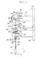
- the cradle 23 includes a cradle main body 60, the larger-diameter side bobbin holding section (winding tube holding section) 43, and a smaller-diameter side bobbin holding section 44.
- the cradle main body 60 includes an arm 61 formed in a substantially U-shape.
- the arm 61 is configured by a first arm 61a, a second arm 61b, and a third arm 61c.
- the larger-diameter side bobbin holding section 43, the package driving motor 41, and the like are mounted on the first arm 61a by an appropriate member.
- the smaller-diameter side bobbin holding section 44 is mounted on the third arm 61c by an appropriate member.
- the second arm 61b connects the first arm 61a and the third arm 61c.
- the larger-diameter side bobbin holding section 43 makes contact with an inner surface of the winding bobbin 22 on a larger-diameter side to hold the winding bobbin 22.
- the smaller-diameter side bobbin holding section 44 makes contact with an inner surface of the winding bobbin 22 on a smaller-diameter side to hold the winding bobbin 22.
- the cradle 23 can slide the larger-diameter side bobbin holding section 43 parallel to the axis of the winding bobbin 22. By sliding the larger-diameter side bobbin holding section 43, the winding bobbin 22 can be held between the larger-diameter side bobbin holding section 43 and the smaller-diameter side bobbin holding section 44, or such holding of the winding bobbin 22 can be released.
- the cradle main body 60 includes, in addition to the arm 61, a casing 62, a supporting flange 63, a regulating flange 64, cylinders 65, and a slide lever 100.
- the cylinders 65 are tubular members. An outer circumferential surface of each of the cylinders 65 is fixed to the first arm 61a.
- Each of the cylinders 65 interiorly includes a slide rod 66 and an urging spring 67.
- One side (the winding bobbin 22 side) of the slide rod 66 is fixed to the supporting flange 63.
- the urging spring 67 is mounted on the other side of the slide rod 66.
- the urging spring 67 urges the slide rod 66 towards the supporting flange 63.
- the casing 62 is a cylindrical member.
- the package driving motor 41 is accommodated inside the casing 62. A driving force generated by the package driving motor 41 is transmitted to the larger-diameter side bobbin holding section 43 via the driving shaft 41a.
- the package driving motor 41 can rotationally drive the winding bobbin 22 (the package 30).
- the supporting flange 63 is fixed to one side (the winding bobbin 22 side) of the casing 62.
- the regulating flange 64 is fixed to the other side of the casing 62.
- the supporting flange 63 is a plate-like member having a substantially diamond shape or a substantially elliptical shape.
- the supporting flange 63 is provided with an inserting hole (not illustrated) to which the driving shaft 41a is inserted.
- the regulating flange 64 is a member having a shape similar to the supporting flange 63.
- the regulating flange 64 is provided with inserting holes to which the cylinders 65 are inserted.
- the supporting flange 63 When the supporting flange 63 receives an urging force of the urging spring 67, the casing 62, the supporting flange 63, and the regulating flange 64 can integrally slide in a direction to approach the winding bobbin 22. Sliding of a prescribed amount or more in the direction to approach the winding bobbin 22 is regulated when the regulating flange 64 makes contact with the first arm 61a.
- the slide lever 100 includes a lever operating section 101, a transmitting arm 102, and a swing shaft 103.
- the lever operating section 101 is a knob provided for the operator to grip and operate.
- the transmitting arm 102 is connected to the lever operating section 101 and the swing shaft 103 to transmit an operation of the lever operating section 101 made by the operator.
- the swing shaft 103 is a center of swing when swinging the slide lever 100.
- An intermediate portion of the transmitting arm 102 is coupled to the casing 62 (specifically, the package driving motor 41) by a coupling member 110.
- the slide lever 100 When the operator grips the lever operating section 101 and applies a force in a direction of moving away from the winding bobbin 22 (clockwise direction in FIG. 4 ), the slide lever 100 can swing in the clockwise direction in FIG. 4 with the swing shaft 103 as the center of swing.
- the coupling member 110 pulls the casing 62 in the direction of moving away from the winding bobbin 22.
- the casing 62, the supporting flange 63, and the regulating flange 64 thus can be integrally slid in the direction of moving away from the winding bobbin 22.
- the sliding of a prescribed amount or more in the direction of moving away from the winding bobbin 22 is regulated when the supporting flange 63 makes contact with the first arm 61a.
- the larger-diameter side bobbin holding section 43 includes a base member 70 and a contact member 80.
- the base member 70 is first mounted on the cradle main body 60, and then the contact member 80 is mounted on the base member 70.
- the base member 70 is made of metal, and is formed by performing drawing processing on the plate-like member, for example.
- the base member 70 is a cylindrical member in which one side (side on which the contact member 80 is mounted, left side in FIG. 5 ) is closed by a circular plate portion 71.
- the circular plate portion 71 is provided with a bolt inserting hole 72, and a driving shaft inserting hole 73.
- a flange-shaped rotation output member (not illustrated), which integrally rotates with the driving shaft 41a, is mounted to the driving shaft 41a of the package driving motor 41.
- the rotation output member is located closer to the winding bobbin 22 than the supporting flange 63.
- the base member 70 is mounted to the rotation output member in a relatively non-rotatable manner. When mounting the base member 70 to the rotation output member, the operator first inserts the driving shaft 41a to the driving shaft inserting hole 73. The operator then aligns a hole formed in the rotation output member and the bolt inserting hole 72, and inserts and tightens a bolt 68 to fix the base member 70 (see FIG. 5 ).
- the contact member 80 is made of a raw material having elasticity (specifically urethane).
- the contact member 80 is a cylindrical member in which one side (side adapted to make contact with the winding bobbin 22, left side in FIG. 6 ) is closed by a circular plate portion 81.
- a circumferential wall 84 formed on a side surface of the contact member 80 surface formed substantially perpendicular to the circular plate portion 81 to contact with the inner surface of the winding bobbin 22, the contact member 80 holds the winding bobbin 22.
- the circular plate portion 81 is provided with a rotation preventing hole (receiving section) 82 and a driving shaft inserting hole 83.
- An inner peripheral surface of the contact member 80 (surface on the side adapted to make contact with the base member 70) is slightly smaller than an outer peripheral surface of the base member 70 (surface on the side adapted to make contact with the contact member 80).
- the operator can mount the contact member 80 to the base member 70 by elastically deforming the contact member 80.
- a head 68a of the bolt 68 (protrusion) and the driving shaft 41a project from the circular plate portion 71.
- the operator mounts the contact member 80 to the base member 70 such that the head 68a is fitted in the rotation preventing hole 82 and the driving shaft 41a is inserted in the driving shaft inserting hole 83 (see FIG. 7 ).
- the head 68a of the bolt 68 pushes the inner peripheral surface of the rotation preventing hole 82, and the contact member 80 integrally rotates with the base member 70.
- the head 68a and the rotation preventing hole 82 function as a rotation preventing section adapted to prevent the relative rotation of the contact member 80 with respect to the base member 70.
- the larger-diameter side bobbin holding section 43 integrally rotates with the driving shaft 41a and can hold the winding bobbin 22. Since the contact member 80 is abraded by the scraping with the winding bobbin 22, or the like, the contact member 80 is required to be replaced at a certain frequency. If the contact member 80 is not replaced, slip easily occurs between the contact member 80 and the winding bobbin 22. When slip occurs, the rotation speed of the driving shaft 41a and the rotation speed of the winding bobbin 22 do not match, and the yarn 20 cannot be wound as controlled by the unit control section 50.
- a bobbin holding section having a configuration in which the base member and the contact member are non--detachably provided. Since this type of bobbin holding section requires the entire bobbin holding section to be replaced when the contact member is abraded, the cost at the time of replacement is increased. In the present embodiment, since the contact member 80 can be detached from the base member 70, only the contact member 80 can be replaced. Therefore, the cost in replacing the contact member 80 can be reduced.
- the base member and the contact member are detachably mounted, for example, if the base member and the contact member are detachably mounted by attaching and detaching the bolt or the like, a work load is caused in replacing the contact member.
- the contact member 80 With a one-touch operation of merely having the operator grip and pull the end of the contact member 80, the contact member 80 can be elastically deformed and detached from the base member 70. As a result, the work load in replacing the contact member 80 can be reduced.
- the cradle 23 of the present embodiment includes the cradle main body 60, the larger-diameter side bobbin holding section 43, and the rotation preventing section.
- the larger-diameter side bobbin holding section 43 is rotatably mounted to the cradle main body 60 and adapted to hold the winding bobbin 22 around which the yarn 20 is wound.
- the larger-diameter bobbin holding section 43 includes the base member 70 and the contact member 80.
- the base member 70 is rotatably mounted to the cradle main body 60.
- the contact member 80 is detachably mounted to the base member 70 by at least a portion of the contact member 80 being elastically deformed, and adapted to hold the winding bobbin 22 by making contact with the winding bobbin 22.
- the rotation preventing section is adapted to prevent relative rotation of the contact member 80 with respect to the base member 70.
- the rotation preventing section includes the head 68a provided on the base member 70 and the rotation preventing hole 82 formed in the contact member 80.
- the head 68a is fitted into the rotation preventing hole 82. Accordingly, the relative rotation of the base member 70 and the contact member 80 can be prevented using the bolt 68, and a protrusion is not required to be specially formed on the base member 70. Therefore, the manufacturing cost of the base member 70 can be reduced.
- an area of a side of the contact member 80 (area of the inner peripheral surface of the contact member 80), the side being adapted to make contact with the base member 70, is smaller than an area of a side of the base member 70 (area of the outer peripheral surface of the base member 70), the side being adapted to make contact with the contact member 80. Accordingly, the contact member 80 is elastically deformed to be mounted on the base member 70, and the base member 70 can reliably hold the contact member 80.
- the contact member 80 is urethane. Therefore, an abrasion resistance property to a certain extent is provided to the cradle 23 while suppressing the slip between the contact member 80 and the winding bobbin 22.
- the cradle 23 of the present embodiment includes the package driving motor 41.
- the package driving motor 41 rotationally drives the winding bobbin 22 by rotating the base member 70.
- the contact member 80 which is easy to replace, is preferably replaced at a certain frequency.
- the rotation preventing section is not limited to the structure described above.
- a protrusion may be formed on the base member 70 in place of the head 68a.
- a receiving section may be formed on the base member 70, and a protrusion may be formed on the contact member 80.
- a protrusion and a receiving section may be formed on the base member 70, and a receiving section and a protrusion corresponding to such protrusion and receiving section may be formed on the contact member 80.
- the receiving section may be a through type (a hole) like the rotation preventing hole 82, or may be a non-through type (a recess).
- the contact member 80 is not limited to urethane as long as the contact member 80 can hold the winding bobbin 22 without slipping, and may be rubber.
- the winder unit 10 winds a general cone winding package.
- the winder unit 10 may wind a package of which an end surface is tapered, or a cheese-shaped package, for example.
- the traverse device 27 may be a belt-type traverse device adapted to reciprocate the traverse guide in a winding width direction of the package by belt drive, a rotary-type traverse device using a rotary blade, or a rod-type traverse device adapted to reciprocate a rod to which the traverse guide is attached.
- the traverse device 27 is not limited to a configuration of reciprocating the traverse guide 28 within a substantially horizontal plane with respect to an installation surface of the winder unit 10.
- a longitudinal direction of the traverse arm may be substantially perpendicular to the installation surface of the winder unit 10.
- the package driving motor 41 is not limited to a servo motor, and may be various types of motors such as a step motor or an induction motor.
- the contact roller 29 may be driven with an appropriate driving device and the package 30 may be rotated accompanying the rotation of the contact roller 29.
- the unit control section 50 controls the package driving motor 41, but a control section dedicated to control the package driving motor 41 may be arranged in the winder unit 10.
- the present invention is not limited to the automatic winder, and can be applied to other yarn winding machines such as a rewinding machine, a fine spinning machine (e.g., an air-jet spinning machine, an open--end spinning machine), and the like.
- a rewinding machine e.g., a rewinding machine, a fine spinning machine (e.g., an air-jet spinning machine, an open--end spinning machine), and the like.
Landscapes
- Engineering & Computer Science (AREA)
- Textile Engineering (AREA)
- Winding Filamentary Materials (AREA)
Applications Claiming Priority (1)
| Application Number | Priority Date | Filing Date | Title |
|---|---|---|---|
| JP2011201972A JP2013063808A (ja) | 2011-09-15 | 2011-09-15 | クレードル、巻取ユニット、及び糸巻取機 |
Publications (3)
| Publication Number | Publication Date |
|---|---|
| EP2570376A2 true EP2570376A2 (de) | 2013-03-20 |
| EP2570376A3 EP2570376A3 (de) | 2015-11-25 |
| EP2570376B1 EP2570376B1 (de) | 2017-07-05 |
Family
ID=46062126
Family Applications (1)
| Application Number | Title | Priority Date | Filing Date |
|---|---|---|---|
| EP12167612.6A Active EP2570376B1 (de) | 2011-09-15 | 2012-05-11 | Wiege, Wickeleinheit und Garnwickelmaschine |
Country Status (3)
| Country | Link |
|---|---|
| EP (1) | EP2570376B1 (de) |
| JP (1) | JP2013063808A (de) |
| CN (1) | CN102992100B (de) |
Cited By (3)
| Publication number | Priority date | Publication date | Assignee | Title |
|---|---|---|---|---|
| CN105668321A (zh) * | 2016-03-24 | 2016-06-15 | 如皋市丁堰纺织有限公司 | 一种纺包芯纱用长丝圆柱丝饼专用装置 |
| CN107399642A (zh) * | 2017-08-30 | 2017-11-28 | 天津市通福金属制品有限公司 | 一种包塑铁丝无架打轴机 |
| LU504192B1 (de) * | 2023-05-11 | 2024-11-11 | Saurer Spinning Solutions Gmbh & Co Kg | Hülsenteller |
Families Citing this family (3)
| Publication number | Priority date | Publication date | Assignee | Title |
|---|---|---|---|---|
| WO2015047893A1 (en) * | 2013-09-27 | 2015-04-02 | Corning Optical Communications LLC | Spool apparatus and methods of winding a length of cable |
| CN105293165B (zh) * | 2015-11-03 | 2018-03-30 | 国网山东济南市历城区供电公司 | 简易放线架 |
| DE102016117612A1 (de) * | 2016-09-19 | 2018-03-22 | Saurer Germany Gmbh & Co. Kg | Rahmenöffnungseinrichtung für einen Spulenrahmen |
Citations (1)
| Publication number | Priority date | Publication date | Assignee | Title |
|---|---|---|---|---|
| JP2006321615A (ja) | 2005-05-19 | 2006-11-30 | Murata Mach Ltd | 糸の巻取装置、及びそれを備える繊維機械 |
Family Cites Families (4)
| Publication number | Priority date | Publication date | Assignee | Title |
|---|---|---|---|---|
| US1870202A (en) * | 1931-08-31 | 1932-08-02 | American Glanzstoff Corp | Twisting cap |
| US2755027A (en) * | 1951-04-25 | 1956-07-17 | Du Pont | Textile bobbin drive |
| US3596847A (en) * | 1969-12-17 | 1971-08-03 | Stevens & Co Inc J P | Air mandrel |
| JP2011162351A (ja) * | 2010-01-15 | 2011-08-25 | Murata Machinery Ltd | 玉揚げ装置 |
-
2011
- 2011-09-15 JP JP2011201972A patent/JP2013063808A/ja not_active Withdrawn
-
2012
- 2012-05-11 EP EP12167612.6A patent/EP2570376B1/de active Active
- 2012-06-04 CN CN201210180466.5A patent/CN102992100B/zh active Active
Patent Citations (1)
| Publication number | Priority date | Publication date | Assignee | Title |
|---|---|---|---|---|
| JP2006321615A (ja) | 2005-05-19 | 2006-11-30 | Murata Mach Ltd | 糸の巻取装置、及びそれを備える繊維機械 |
Cited By (4)
| Publication number | Priority date | Publication date | Assignee | Title |
|---|---|---|---|---|
| CN105668321A (zh) * | 2016-03-24 | 2016-06-15 | 如皋市丁堰纺织有限公司 | 一种纺包芯纱用长丝圆柱丝饼专用装置 |
| CN107399642A (zh) * | 2017-08-30 | 2017-11-28 | 天津市通福金属制品有限公司 | 一种包塑铁丝无架打轴机 |
| LU504192B1 (de) * | 2023-05-11 | 2024-11-11 | Saurer Spinning Solutions Gmbh & Co Kg | Hülsenteller |
| EP4461683A1 (de) * | 2023-05-11 | 2024-11-13 | Saurer Spinning Solutions GmbH & Co. KG | Hülsenteller |
Also Published As
| Publication number | Publication date |
|---|---|
| CN102992100A (zh) | 2013-03-27 |
| EP2570376A3 (de) | 2015-11-25 |
| EP2570376B1 (de) | 2017-07-05 |
| JP2013063808A (ja) | 2013-04-11 |
| CN102992100B (zh) | 2016-12-14 |
Similar Documents
| Publication | Publication Date | Title |
|---|---|---|
| EP2570376B1 (de) | Wiege, Wickeleinheit und Garnwickelmaschine | |
| EP2169096B1 (de) | Spinnmaschine | |
| EP2284300B1 (de) | Spinnmaschine und Garnentfernungsverfahren zum Entfernen von verbleibendem Garn auf der Garnzusammentragungsrolle | |
| EP2479129B1 (de) | Garnwicklungsmaschine | |
| EP2075359B1 (de) | Vorrichtung zur Beseitigung von Fadenlockerungen und Spinnmaschine | |
| CN1333122C (zh) | 用于纺纱机的纱线松弛消除装置 | |
| EP2105398A2 (de) | Garnwicklungsvorrichtung | |
| EP2511214A1 (de) | Garnwickelvorrichtung und automatischer Wickler | |
| EP2570377B1 (de) | Changierführungselement, Wickeleinheit und Wickelmaschine | |
| EP2567922B1 (de) | Wachsvorrichtung, Spinneinheit und Spinnmaschine | |
| JP2012218922A (ja) | 糸巻取機及び糸引き出し方法 | |
| US20080283655A1 (en) | Method and device for operating a winding device of a textile machine producing cross-wound bobbins | |
| JP6080428B2 (ja) | 綾巻きパッケージを製造する繊維機械のための糸スプライシング装置 | |
| EP2159180A2 (de) | Garnwickelvorrichtung und automatischer Wickler | |
| EP2962973A1 (de) | Garnwicklungsvorrichtung | |
| EP2530039B1 (de) | Garnwicklungsvorrichtung | |
| EP2366649A2 (de) | Garnwicklungsmaschine | |
| EP2990367A1 (de) | Garnwickelvorrichtung | |
| EP2977493B1 (de) | Spinnmaschine und spinnverfahren | |
| EP2028149B1 (de) | Vorrichtung zur Wicklungsspannungssteuerung | |
| EP2749516B1 (de) | Garnhinausführungsvorrichtung und Garnwickelmaschine | |
| EP2700601A2 (de) | Garnwickeleinheit und Garnwickelmaschine | |
| JP2014094786A (ja) | 綾振装置およびこれを備えた巻取装置 | |
| JP2013063838A (ja) | 糸巻取機 | |
| CN111132918B (zh) | 纱线卷取机 |
Legal Events
| Date | Code | Title | Description |
|---|---|---|---|
| PUAI | Public reference made under article 153(3) epc to a published international application that has entered the european phase |
Free format text: ORIGINAL CODE: 0009012 |
|
| AK | Designated contracting states |
Kind code of ref document: A2 Designated state(s): AL AT BE BG CH CY CZ DE DK EE ES FI FR GB GR HR HU IE IS IT LI LT LU LV MC MK MT NL NO PL PT RO RS SE SI SK SM TR |
|
| AX | Request for extension of the european patent |
Extension state: BA ME |
|
| PUAL | Search report despatched |
Free format text: ORIGINAL CODE: 0009013 |
|
| AK | Designated contracting states |
Kind code of ref document: A3 Designated state(s): AL AT BE BG CH CY CZ DE DK EE ES FI FR GB GR HR HU IE IS IT LI LT LU LV MC MK MT NL NO PL PT RO RS SE SI SK SM TR |
|
| AX | Request for extension of the european patent |
Extension state: BA ME |
|
| RIC1 | Information provided on ipc code assigned before grant |
Ipc: B65H 54/74 20060101ALI20151016BHEP Ipc: B65H 54/54 20060101ALI20151016BHEP Ipc: B65H 54/553 20060101AFI20151016BHEP |
|
| 17P | Request for examination filed |
Effective date: 20160302 |
|
| RBV | Designated contracting states (corrected) |
Designated state(s): AL AT BE BG CH CY CZ DE DK EE ES FI FR GB GR HR HU IE IS IT LI LT LU LV MC MK MT NL NO PL PT RO RS SE SI SK SM TR |
|
| GRAP | Despatch of communication of intention to grant a patent |
Free format text: ORIGINAL CODE: EPIDOSNIGR1 |
|
| INTG | Intention to grant announced |
Effective date: 20170126 |
|
| RIN1 | Information on inventor provided before grant (corrected) |
Inventor name: TANIGAWA, YASUNOBU |
|
| GRAS | Grant fee paid |
Free format text: ORIGINAL CODE: EPIDOSNIGR3 |
|
| GRAA | (expected) grant |
Free format text: ORIGINAL CODE: 0009210 |
|
| AK | Designated contracting states |
Kind code of ref document: B1 Designated state(s): AL AT BE BG CH CY CZ DE DK EE ES FI FR GB GR HR HU IE IS IT LI LT LU LV MC MK MT NL NO PL PT RO RS SE SI SK SM TR |
|
| REG | Reference to a national code |
Ref country code: GB Ref legal event code: FG4D |
|
| REG | Reference to a national code |
Ref country code: CH Ref legal event code: EP |
|
| REG | Reference to a national code |
Ref country code: AT Ref legal event code: REF Ref document number: 906450 Country of ref document: AT Kind code of ref document: T Effective date: 20170715 |
|
| REG | Reference to a national code |
Ref country code: IE Ref legal event code: FG4D |
|
| REG | Reference to a national code |
Ref country code: DE Ref legal event code: R096 Ref document number: 602012034127 Country of ref document: DE |
|
| REG | Reference to a national code |
Ref country code: NL Ref legal event code: MP Effective date: 20170705 |
|
| REG | Reference to a national code |
Ref country code: AT Ref legal event code: MK05 Ref document number: 906450 Country of ref document: AT Kind code of ref document: T Effective date: 20170705 |
|
| REG | Reference to a national code |
Ref country code: LT Ref legal event code: MG4D |
|
| PG25 | Lapsed in a contracting state [announced via postgrant information from national office to epo] |
Ref country code: NO Free format text: LAPSE BECAUSE OF FAILURE TO SUBMIT A TRANSLATION OF THE DESCRIPTION OR TO PAY THE FEE WITHIN THE PRESCRIBED TIME-LIMIT Effective date: 20171005 Ref country code: LT Free format text: LAPSE BECAUSE OF FAILURE TO SUBMIT A TRANSLATION OF THE DESCRIPTION OR TO PAY THE FEE WITHIN THE PRESCRIBED TIME-LIMIT Effective date: 20170705 Ref country code: HR Free format text: LAPSE BECAUSE OF FAILURE TO SUBMIT A TRANSLATION OF THE DESCRIPTION OR TO PAY THE FEE WITHIN THE PRESCRIBED TIME-LIMIT Effective date: 20170705 Ref country code: AT Free format text: LAPSE BECAUSE OF FAILURE TO SUBMIT A TRANSLATION OF THE DESCRIPTION OR TO PAY THE FEE WITHIN THE PRESCRIBED TIME-LIMIT Effective date: 20170705 Ref country code: FI Free format text: LAPSE BECAUSE OF FAILURE TO SUBMIT A TRANSLATION OF THE DESCRIPTION OR TO PAY THE FEE WITHIN THE PRESCRIBED TIME-LIMIT Effective date: 20170705 Ref country code: NL Free format text: LAPSE BECAUSE OF FAILURE TO SUBMIT A TRANSLATION OF THE DESCRIPTION OR TO PAY THE FEE WITHIN THE PRESCRIBED TIME-LIMIT Effective date: 20170705 Ref country code: SE Free format text: LAPSE BECAUSE OF FAILURE TO SUBMIT A TRANSLATION OF THE DESCRIPTION OR TO PAY THE FEE WITHIN THE PRESCRIBED TIME-LIMIT Effective date: 20170705 |
|
| PG25 | Lapsed in a contracting state [announced via postgrant information from national office to epo] |
Ref country code: LV Free format text: LAPSE BECAUSE OF FAILURE TO SUBMIT A TRANSLATION OF THE DESCRIPTION OR TO PAY THE FEE WITHIN THE PRESCRIBED TIME-LIMIT Effective date: 20170705 Ref country code: ES Free format text: LAPSE BECAUSE OF FAILURE TO SUBMIT A TRANSLATION OF THE DESCRIPTION OR TO PAY THE FEE WITHIN THE PRESCRIBED TIME-LIMIT Effective date: 20170705 Ref country code: IS Free format text: LAPSE BECAUSE OF FAILURE TO SUBMIT A TRANSLATION OF THE DESCRIPTION OR TO PAY THE FEE WITHIN THE PRESCRIBED TIME-LIMIT Effective date: 20171105 Ref country code: RS Free format text: LAPSE BECAUSE OF FAILURE TO SUBMIT A TRANSLATION OF THE DESCRIPTION OR TO PAY THE FEE WITHIN THE PRESCRIBED TIME-LIMIT Effective date: 20170705 Ref country code: GR Free format text: LAPSE BECAUSE OF FAILURE TO SUBMIT A TRANSLATION OF THE DESCRIPTION OR TO PAY THE FEE WITHIN THE PRESCRIBED TIME-LIMIT Effective date: 20171006 Ref country code: BG Free format text: LAPSE BECAUSE OF FAILURE TO SUBMIT A TRANSLATION OF THE DESCRIPTION OR TO PAY THE FEE WITHIN THE PRESCRIBED TIME-LIMIT Effective date: 20171005 Ref country code: PL Free format text: LAPSE BECAUSE OF FAILURE TO SUBMIT A TRANSLATION OF THE DESCRIPTION OR TO PAY THE FEE WITHIN THE PRESCRIBED TIME-LIMIT Effective date: 20170705 |
|
| REG | Reference to a national code |
Ref country code: DE Ref legal event code: R097 Ref document number: 602012034127 Country of ref document: DE |
|
| PG25 | Lapsed in a contracting state [announced via postgrant information from national office to epo] |
Ref country code: RO Free format text: LAPSE BECAUSE OF FAILURE TO SUBMIT A TRANSLATION OF THE DESCRIPTION OR TO PAY THE FEE WITHIN THE PRESCRIBED TIME-LIMIT Effective date: 20170705 Ref country code: DK Free format text: LAPSE BECAUSE OF FAILURE TO SUBMIT A TRANSLATION OF THE DESCRIPTION OR TO PAY THE FEE WITHIN THE PRESCRIBED TIME-LIMIT Effective date: 20170705 Ref country code: CZ Free format text: LAPSE BECAUSE OF FAILURE TO SUBMIT A TRANSLATION OF THE DESCRIPTION OR TO PAY THE FEE WITHIN THE PRESCRIBED TIME-LIMIT Effective date: 20170705 |
|
| PLBE | No opposition filed within time limit |
Free format text: ORIGINAL CODE: 0009261 |
|
| STAA | Information on the status of an ep patent application or granted ep patent |
Free format text: STATUS: NO OPPOSITION FILED WITHIN TIME LIMIT |
|
| PG25 | Lapsed in a contracting state [announced via postgrant information from national office to epo] |
Ref country code: SM Free format text: LAPSE BECAUSE OF FAILURE TO SUBMIT A TRANSLATION OF THE DESCRIPTION OR TO PAY THE FEE WITHIN THE PRESCRIBED TIME-LIMIT Effective date: 20170705 Ref country code: EE Free format text: LAPSE BECAUSE OF FAILURE TO SUBMIT A TRANSLATION OF THE DESCRIPTION OR TO PAY THE FEE WITHIN THE PRESCRIBED TIME-LIMIT Effective date: 20170705 Ref country code: SK Free format text: LAPSE BECAUSE OF FAILURE TO SUBMIT A TRANSLATION OF THE DESCRIPTION OR TO PAY THE FEE WITHIN THE PRESCRIBED TIME-LIMIT Effective date: 20170705 |
|
| 26N | No opposition filed |
Effective date: 20180406 |
|
| PGFP | Annual fee paid to national office [announced via postgrant information from national office to epo] |
Ref country code: DE Payment date: 20180522 Year of fee payment: 7 |
|
| PG25 | Lapsed in a contracting state [announced via postgrant information from national office to epo] |
Ref country code: SI Free format text: LAPSE BECAUSE OF FAILURE TO SUBMIT A TRANSLATION OF THE DESCRIPTION OR TO PAY THE FEE WITHIN THE PRESCRIBED TIME-LIMIT Effective date: 20170705 |
|
| REG | Reference to a national code |
Ref country code: CH Ref legal event code: PL |
|
| GBPC | Gb: european patent ceased through non-payment of renewal fee |
Effective date: 20180511 |
|
| REG | Reference to a national code |
Ref country code: BE Ref legal event code: MM Effective date: 20180531 |
|
| PG25 | Lapsed in a contracting state [announced via postgrant information from national office to epo] |
Ref country code: MC Free format text: LAPSE BECAUSE OF FAILURE TO SUBMIT A TRANSLATION OF THE DESCRIPTION OR TO PAY THE FEE WITHIN THE PRESCRIBED TIME-LIMIT Effective date: 20170705 |
|
| REG | Reference to a national code |
Ref country code: IE Ref legal event code: MM4A |
|
| PG25 | Lapsed in a contracting state [announced via postgrant information from national office to epo] |
Ref country code: LI Free format text: LAPSE BECAUSE OF NON-PAYMENT OF DUE FEES Effective date: 20180531 Ref country code: CH Free format text: LAPSE BECAUSE OF NON-PAYMENT OF DUE FEES Effective date: 20180531 |
|
| PG25 | Lapsed in a contracting state [announced via postgrant information from national office to epo] |
Ref country code: LU Free format text: LAPSE BECAUSE OF NON-PAYMENT OF DUE FEES Effective date: 20180511 |
|
| PG25 | Lapsed in a contracting state [announced via postgrant information from national office to epo] |
Ref country code: GB Free format text: LAPSE BECAUSE OF NON-PAYMENT OF DUE FEES Effective date: 20180511 Ref country code: FR Free format text: LAPSE BECAUSE OF NON-PAYMENT OF DUE FEES Effective date: 20180531 Ref country code: IE Free format text: LAPSE BECAUSE OF NON-PAYMENT OF DUE FEES Effective date: 20180511 |
|
| PG25 | Lapsed in a contracting state [announced via postgrant information from national office to epo] |
Ref country code: BE Free format text: LAPSE BECAUSE OF NON-PAYMENT OF DUE FEES Effective date: 20180531 |
|
| REG | Reference to a national code |
Ref country code: DE Ref legal event code: R119 Ref document number: 602012034127 Country of ref document: DE |
|
| PG25 | Lapsed in a contracting state [announced via postgrant information from national office to epo] |
Ref country code: MT Free format text: LAPSE BECAUSE OF NON-PAYMENT OF DUE FEES Effective date: 20180511 |
|
| PG25 | Lapsed in a contracting state [announced via postgrant information from national office to epo] |
Ref country code: TR Free format text: LAPSE BECAUSE OF FAILURE TO SUBMIT A TRANSLATION OF THE DESCRIPTION OR TO PAY THE FEE WITHIN THE PRESCRIBED TIME-LIMIT Effective date: 20170705 |
|
| PG25 | Lapsed in a contracting state [announced via postgrant information from national office to epo] |
Ref country code: DE Free format text: LAPSE BECAUSE OF NON-PAYMENT OF DUE FEES Effective date: 20191203 |
|
| PG25 | Lapsed in a contracting state [announced via postgrant information from national office to epo] |
Ref country code: PT Free format text: LAPSE BECAUSE OF FAILURE TO SUBMIT A TRANSLATION OF THE DESCRIPTION OR TO PAY THE FEE WITHIN THE PRESCRIBED TIME-LIMIT Effective date: 20170705 Ref country code: HU Free format text: LAPSE BECAUSE OF FAILURE TO SUBMIT A TRANSLATION OF THE DESCRIPTION OR TO PAY THE FEE WITHIN THE PRESCRIBED TIME-LIMIT; INVALID AB INITIO Effective date: 20120511 |
|
| PG25 | Lapsed in a contracting state [announced via postgrant information from national office to epo] |
Ref country code: MK Free format text: LAPSE BECAUSE OF NON-PAYMENT OF DUE FEES Effective date: 20170705 Ref country code: CY Free format text: LAPSE BECAUSE OF FAILURE TO SUBMIT A TRANSLATION OF THE DESCRIPTION OR TO PAY THE FEE WITHIN THE PRESCRIBED TIME-LIMIT Effective date: 20170705 |
|
| PG25 | Lapsed in a contracting state [announced via postgrant information from national office to epo] |
Ref country code: AL Free format text: LAPSE BECAUSE OF FAILURE TO SUBMIT A TRANSLATION OF THE DESCRIPTION OR TO PAY THE FEE WITHIN THE PRESCRIBED TIME-LIMIT Effective date: 20170705 |
|
| PGFP | Annual fee paid to national office [announced via postgrant information from national office to epo] |
Ref country code: IT Payment date: 20240418 Year of fee payment: 13 |