EP2570152B1 - Strukturierte Sonden für neurale Anwendungen - Google Patents
Strukturierte Sonden für neurale Anwendungen Download PDFInfo
- Publication number
- EP2570152B1 EP2570152B1 EP11181696.3A EP11181696A EP2570152B1 EP 2570152 B1 EP2570152 B1 EP 2570152B1 EP 11181696 A EP11181696 A EP 11181696A EP 2570152 B1 EP2570152 B1 EP 2570152B1
- Authority
- EP
- European Patent Office
- Prior art keywords
- probe
- shanks
- shank
- mask pattern
- etch mask
- Prior art date
- Legal status (The legal status is an assumption and is not a legal conclusion. Google has not performed a legal analysis and makes no representation as to the accuracy of the status listed.)
- Active
Links
- 239000000523 sample Substances 0.000 title claims description 235
- 230000001537 neural effect Effects 0.000 title description 9
- 238000000034 method Methods 0.000 claims description 99
- 239000000758 substrate Substances 0.000 claims description 72
- 230000004936 stimulating effect Effects 0.000 claims description 45
- 210000004556 brain Anatomy 0.000 claims description 44
- 230000008569 process Effects 0.000 claims description 36
- 230000000638 stimulation Effects 0.000 claims description 29
- 230000000873 masking effect Effects 0.000 claims description 25
- 238000001312 dry etching Methods 0.000 claims description 20
- 238000004519 manufacturing process Methods 0.000 claims description 19
- 238000005530 etching Methods 0.000 description 44
- 238000000227 grinding Methods 0.000 description 44
- 239000000463 material Substances 0.000 description 18
- 238000005452 bending Methods 0.000 description 13
- 238000005520 cutting process Methods 0.000 description 13
- 238000001020 plasma etching Methods 0.000 description 12
- 238000005498 polishing Methods 0.000 description 11
- VYPSYNLAJGMNEJ-UHFFFAOYSA-N Silicium dioxide Chemical compound O=[Si]=O VYPSYNLAJGMNEJ-UHFFFAOYSA-N 0.000 description 10
- XUIMIQQOPSSXEZ-UHFFFAOYSA-N Silicon Chemical compound [Si] XUIMIQQOPSSXEZ-UHFFFAOYSA-N 0.000 description 10
- 239000002184 metal Substances 0.000 description 10
- 229910052751 metal Inorganic materials 0.000 description 10
- 229910052710 silicon Inorganic materials 0.000 description 10
- 239000010703 silicon Substances 0.000 description 10
- 238000000059 patterning Methods 0.000 description 9
- 230000036961 partial effect Effects 0.000 description 8
- BASFCYQUMIYNBI-UHFFFAOYSA-N platinum Substances [Pt] BASFCYQUMIYNBI-UHFFFAOYSA-N 0.000 description 8
- 235000012431 wafers Nutrition 0.000 description 8
- 230000008901 benefit Effects 0.000 description 7
- 238000000708 deep reactive-ion etching Methods 0.000 description 7
- 210000001951 dura mater Anatomy 0.000 description 7
- 238000002161 passivation Methods 0.000 description 7
- 239000010936 titanium Substances 0.000 description 6
- 238000001039 wet etching Methods 0.000 description 6
- 210000005013 brain tissue Anatomy 0.000 description 5
- 238000000151 deposition Methods 0.000 description 5
- 238000005516 engineering process Methods 0.000 description 5
- 238000003780 insertion Methods 0.000 description 5
- 230000037431 insertion Effects 0.000 description 5
- 229920002120 photoresistant polymer Polymers 0.000 description 5
- XPDWGBQVDMORPB-UHFFFAOYSA-N Fluoroform Chemical compound FC(F)F XPDWGBQVDMORPB-UHFFFAOYSA-N 0.000 description 4
- 230000000694 effects Effects 0.000 description 4
- 238000002513 implantation Methods 0.000 description 4
- 238000002955 isolation Methods 0.000 description 4
- 230000035515 penetration Effects 0.000 description 4
- 230000002829 reductive effect Effects 0.000 description 4
- 229910052814 silicon oxide Inorganic materials 0.000 description 4
- 239000010409 thin film Substances 0.000 description 4
- 241001269524 Dura Species 0.000 description 3
- KRHYYFGTRYWZRS-UHFFFAOYSA-N Fluorane Chemical compound F KRHYYFGTRYWZRS-UHFFFAOYSA-N 0.000 description 3
- 229910020776 SixNy Inorganic materials 0.000 description 3
- 238000005229 chemical vapour deposition Methods 0.000 description 3
- 239000002131 composite material Substances 0.000 description 3
- 230000008021 deposition Effects 0.000 description 3
- 230000008020 evaporation Effects 0.000 description 3
- 238000001704 evaporation Methods 0.000 description 3
- 239000003292 glue Substances 0.000 description 3
- 239000010931 gold Substances 0.000 description 3
- 230000000670 limiting effect Effects 0.000 description 3
- 238000004518 low pressure chemical vapour deposition Methods 0.000 description 3
- 239000000377 silicon dioxide Substances 0.000 description 3
- TXEYQDLBPFQVAA-UHFFFAOYSA-N tetrafluoromethane Chemical compound FC(F)(F)F TXEYQDLBPFQVAA-UHFFFAOYSA-N 0.000 description 3
- BLIQUJLAJXRXSG-UHFFFAOYSA-N 1-benzyl-3-(trifluoromethyl)pyrrolidin-1-ium-3-carboxylate Chemical compound C1C(C(=O)O)(C(F)(F)F)CCN1CC1=CC=CC=C1 BLIQUJLAJXRXSG-UHFFFAOYSA-N 0.000 description 2
- XKRFYHLGVUSROY-UHFFFAOYSA-N Argon Chemical compound [Ar] XKRFYHLGVUSROY-UHFFFAOYSA-N 0.000 description 2
- ZOXJGFHDIHLPTG-UHFFFAOYSA-N Boron Chemical compound [B] ZOXJGFHDIHLPTG-UHFFFAOYSA-N 0.000 description 2
- 238000009623 Bosch process Methods 0.000 description 2
- 229910052581 Si3N4 Inorganic materials 0.000 description 2
- RTAQQCXQSZGOHL-UHFFFAOYSA-N Titanium Chemical compound [Ti] RTAQQCXQSZGOHL-UHFFFAOYSA-N 0.000 description 2
- 239000000853 adhesive Substances 0.000 description 2
- 230000001070 adhesive effect Effects 0.000 description 2
- 229910052782 aluminium Inorganic materials 0.000 description 2
- XAGFODPZIPBFFR-UHFFFAOYSA-N aluminium Chemical compound [Al] XAGFODPZIPBFFR-UHFFFAOYSA-N 0.000 description 2
- 229910052796 boron Inorganic materials 0.000 description 2
- 239000012876 carrier material Substances 0.000 description 2
- 230000001419 dependent effect Effects 0.000 description 2
- 238000013461 design Methods 0.000 description 2
- 239000002019 doping agent Substances 0.000 description 2
- 238000001017 electron-beam sputter deposition Methods 0.000 description 2
- 238000009713 electroplating Methods 0.000 description 2
- PCHJSUWPFVWCPO-UHFFFAOYSA-N gold Chemical compound [Au] PCHJSUWPFVWCPO-UHFFFAOYSA-N 0.000 description 2
- 229910052737 gold Inorganic materials 0.000 description 2
- 239000012528 membrane Substances 0.000 description 2
- 210000002569 neuron Anatomy 0.000 description 2
- 229910052697 platinum Inorganic materials 0.000 description 2
- 229920000642 polymer Polymers 0.000 description 2
- 230000002787 reinforcement Effects 0.000 description 2
- 239000004065 semiconductor Substances 0.000 description 2
- HQVNEWCFYHHQES-UHFFFAOYSA-N silicon nitride Chemical compound N12[Si]34N5[Si]62N3[Si]51N64 HQVNEWCFYHHQES-UHFFFAOYSA-N 0.000 description 2
- 239000007787 solid Substances 0.000 description 2
- 238000004544 sputter deposition Methods 0.000 description 2
- 238000007736 thin film deposition technique Methods 0.000 description 2
- 229910052719 titanium Inorganic materials 0.000 description 2
- 229920000049 Carbon (fiber) Polymers 0.000 description 1
- 241000282560 Macaca mulatta Species 0.000 description 1
- 229910052786 argon Inorganic materials 0.000 description 1
- QVGXLLKOCUKJST-UHFFFAOYSA-N atomic oxygen Chemical compound [O] QVGXLLKOCUKJST-UHFFFAOYSA-N 0.000 description 1
- 239000000227 bioadhesive Substances 0.000 description 1
- 230000015572 biosynthetic process Effects 0.000 description 1
- 230000000903 blocking effect Effects 0.000 description 1
- 239000004917 carbon fiber Substances 0.000 description 1
- 230000008859 change Effects 0.000 description 1
- 230000006835 compression Effects 0.000 description 1
- 238000007906 compression Methods 0.000 description 1
- 238000006073 displacement reaction Methods 0.000 description 1
- 239000007772 electrode material Substances 0.000 description 1
- 238000005566 electron beam evaporation Methods 0.000 description 1
- 238000005328 electron beam physical vapour deposition Methods 0.000 description 1
- 238000000313 electron-beam-induced deposition Methods 0.000 description 1
- 239000007789 gas Substances 0.000 description 1
- 239000007943 implant Substances 0.000 description 1
- 230000006872 improvement Effects 0.000 description 1
- 230000001939 inductive effect Effects 0.000 description 1
- 208000015181 infectious disease Diseases 0.000 description 1
- 230000010354 integration Effects 0.000 description 1
- 238000011068 loading method Methods 0.000 description 1
- 238000001465 metallisation Methods 0.000 description 1
- 150000002739 metals Chemical class 0.000 description 1
- VNWKTOKETHGBQD-UHFFFAOYSA-N methane Chemical compound C VNWKTOKETHGBQD-UHFFFAOYSA-N 0.000 description 1
- 238000012986 modification Methods 0.000 description 1
- 230000004048 modification Effects 0.000 description 1
- QPJSUIGXIBEQAC-UHFFFAOYSA-N n-(2,4-dichloro-5-propan-2-yloxyphenyl)acetamide Chemical compound CC(C)OC1=CC(NC(C)=O)=C(Cl)C=C1Cl QPJSUIGXIBEQAC-UHFFFAOYSA-N 0.000 description 1
- 239000001301 oxygen Substances 0.000 description 1
- 229910052760 oxygen Inorganic materials 0.000 description 1
- 230000000149 penetrating effect Effects 0.000 description 1
- 238000000206 photolithography Methods 0.000 description 1
- 238000005240 physical vapour deposition Methods 0.000 description 1
- 238000000623 plasma-assisted chemical vapour deposition Methods 0.000 description 1
- 238000003825 pressing Methods 0.000 description 1
- 238000012545 processing Methods 0.000 description 1
- 239000011347 resin Substances 0.000 description 1
- 229920005989 resin Polymers 0.000 description 1
- 235000012239 silicon dioxide Nutrition 0.000 description 1
- 230000003068 static effect Effects 0.000 description 1
- 239000000126 substance Substances 0.000 description 1
- 238000001356 surgical procedure Methods 0.000 description 1
- 230000008719 thickening Effects 0.000 description 1
- 238000012546 transfer Methods 0.000 description 1
Images


Classifications
-
- A—HUMAN NECESSITIES
- A61—MEDICAL OR VETERINARY SCIENCE; HYGIENE
- A61N—ELECTROTHERAPY; MAGNETOTHERAPY; RADIATION THERAPY; ULTRASOUND THERAPY
- A61N1/00—Electrotherapy; Circuits therefor
- A61N1/02—Details
- A61N1/04—Electrodes
- A61N1/05—Electrodes for implantation or insertion into the body, e.g. heart electrode
- A61N1/0526—Head electrodes
- A61N1/0529—Electrodes for brain stimulation
- A61N1/0531—Brain cortex electrodes
-
- A—HUMAN NECESSITIES
- A61—MEDICAL OR VETERINARY SCIENCE; HYGIENE
- A61N—ELECTROTHERAPY; MAGNETOTHERAPY; RADIATION THERAPY; ULTRASOUND THERAPY
- A61N1/00—Electrotherapy; Circuits therefor
- A61N1/02—Details
- A61N1/04—Electrodes
- A61N1/05—Electrodes for implantation or insertion into the body, e.g. heart electrode
- A61N1/0526—Head electrodes
- A61N1/0529—Electrodes for brain stimulation
- A61N1/0534—Electrodes for deep brain stimulation
Definitions
- the present invention relates to a probe for brain recording or stimulation and a method for fabricating the same.
- a neural microelectrode also called neural probe
- a neural probe can be inserted into a brain until the tip reaches the region of the brain to be stimulated/recorded.
- a major criterion for the neural microelectrode design is to have as minimal a footprint as possible to minimize damage to the brain tissue and neuron network.
- a shank thickness of less than 50 ⁇ m for silicon-based probes is preferred.
- the design and fabrication of the microelectrodes is further complicated.
- the electrodes should have the ability to withstand the different types of forces during the insertion phase of the surgical implantation of the probe.
- the main forces that act upon the electrode probe during handling and insertion into the brain tissue are: the bending force which is a result of the out-of-plane loading causing parallel displacement to the tissue plane, the buckling force which occurs under axial compression as a result of the force that counteracts the normal force exerted on the brain tissue by the probe, and the shear force that prevents the tip of the probe from slipping on the surface of the brain tissue.
- the fragility of the probe also increases, particularly when relatively brittle materials such as silicon are used.
- US2009012593 discloses a multiple-electrode probe for deep brain stimulation whereby reinforcements are used.
- the neural probe comprises longitudinal beam structures made of a biocompatible metal or carbon fiber.
- U.S. Pat. N°5,855,801 discloses a micro needle fabricated by using heavy boron doping to define the shape of the probe cross-section. The probe is sequentially reinforced by thickening the probe by leaving undoped silicon on the probe. Such a heavy boron doping is typically incompatible with the integration of electronics on the shaft itself.
- US2010/0331935 discloses a thin film spine-reinforced microelectrode array probe for analyzing neuronal activity, has elongated rigid spine fixedly connected with probe body using bio-adhesive material to structurally reinforce probe body.
- the present invention relates to a method for manufacturing a probe for brain recording and/or stimulation, said probe comprising one or more shanks having a same orientation, wherein each of said shanks has a first side and a second side opposed to said first side and comprises at least one recording and/or stimulating site on said first side and a fin (or fins) protruding perpendicularly from said second side and running on at least a part of the length of said shank along said same orientation, wherein each of said shanks has a sharp pointed tip at its distal end, said tip lying in the plane defined by said first side.
- the method according to the invention comprises the steps of:
- etching encompass both dry-etching and wet-etching but dry-etching is advantageous due to its anisotropic character.
- Wet-etching can be made anisotropic e.g. by using a (110) Si substrate.
- the method according to the invention is advantageous as it permits the production of thin shanks having a rigidity in the direction perpendicular to the surface of their first or second side which is similar to the rigidity of thicker shanks.
- This rigidity is about the same as the rigidity of a shank not having said fin but having a thickness equal to the sum of the thickness of the shank and the height of the fin.
- the shanks of the present invention are therefore rigid enough to penetrate the brain without bending while being thin enough to minimize damage to the brain.
- the method provides said shank(s) with a T-shaped cross-section.
- the present invention relates to a method for manufacturing a probe for brain recording and/or stimulation, said probe comprising a connector part from which one or more shanks protrude along a same orientation, wherein each of said shanks has a first side and a second side opposed to said first side and comprises at least one recording and/or stimulating site on said first side and a fin (or fins) protruding perpendicularly from said second side and running on at least a part of the length of said shank along said same orientation, thereby preferably providing said shank with a T-shaped cross-section, the method comprising the steps of:
- the present invention relates to a probe for brain recording and/or stimulation, said probe comprising one or more shanks having a same orientation, wherein each of said shanks has a first side and a second side opposed to said first side and comprises at least one recording and/or stimulating site on said first side and a fin (or fins) protruding perpendicularly from said second side and running on at least a part of the length of said shank along said same orientation, wherein each of said shanks has a sharp pointed tip at its distal end, said tip lying in the plane defined by said first side.
- said fins are thereby providing said shank with a T-shaped cross-section.
- said probe may comprise shanks having a T-shaped profile, said T-shape being defined by a horizontal part and a vertical part, wherein said horizontal part has a first side and a second side, wherein said vertical part is attached to said second side, and wherein said first surface comprises one or more stimulating and/or recording sites (e.g. electrodes).
- said first surface comprises one or more stimulating and/or recording sites (e.g. electrodes).
- An advantage of embodiments of the present invention is that the second moment of inertia of the shanks of the probe is increased while maintaining a total cross-sectional area as small as possible.
- a probe for brain recording and/or stimulation comprises one or more shanks having a same orientation, wherein each of said shanks has a first side and a second side opposed to said first side and comprises at least one recording and/or stimulating site on said first side and a fin protruding perpendicularly from said second side and running on at least a part of the length of said shank along said same orientation, each of said shanks having a sharp pointed tip at its distal end, said tip lying in the plane defined by said first side.
- the probe may comprise at least one shank being a first shank according to any embodiment of the second aspect, which fin is further attached to either:
- Such an H-shaped profile further rigidifies the shank and provides (in cases (a) and (b) two surfaces for recording and/or stimulating.
- Such an H-shaped shank is easier to insert in a brain than a flat shank of total thickness lower than the total thickness of the H-shaped profile. The reason is that in the H-shaped profile, each of the two shanks composing the H-shape can be thinner than the flat shank, even if the total structure is thicker. The fin being relatively thin, it does not interfere much with the penetration of the H-shaped shank.
- the distance between two adjacent shanks in the first set is equal to the distance between two adjacent shanks in the second set.
- the present disclosure relates to a method of fabricating a probe for brain recording or stimulation, said probe having two parallel sets of shanks (e.g. comprising shanks having a H-shaped cross-section), the method comprising the step of attaching the free extremity of the fin of a shank of a probe according to any embodiment of the second aspect to either:
- the fin of said second shank may belong to a second probe for brain recording and/or stimulation, comprising one or more shanks having said same orientation.
- the present disclosure relates to a probe comprising one or more shanks having a same orientation, wherein each of said shanks has a first side and a second side opposed to said first side and comprises at least one recording and/or stimulating site on said first side which second side is attached to the second side of a second shank having a first side and a second side opposed to said first side and comprising at least one recording and/or stimulating site on said first side, thereby providing a probe having two parallel sets of shanks, wherein each shank in the first set is linked to a shank in the second set.
- the distance between two adjacent shanks in the first set is equal to the distance between two adjacent shanks in the second set.
- the present invention relates to a method for manufacturing a probe for brain recording and/or stimulation, said probe comprising one or more shanks having a same orientation, wherein each of said shanks has a first side and a second side opposed to said first side and comprises at least one recording and/or stimulating site on said first side and a fin protruding perpendicularly from said second side and running on at least a part of the length of said shank along said same orientation, preferably thereby providing said shank with a T-shaped cross-section.
- the method may comprise the steps of:
- the method may further comprise the step (a3) of cutting out at least partially said probe from said substrate and the step (b) of sharpening the distal end of said shanks in such a way as to provide said shanks with a sharp pointed tip at their distal end, said tip lying in the plane defined by said first side.
- the method may comprise the steps of:
- said sharpening may comprise the steps of
- the shanks may be attached via their fins or via other means.
- a major portion of the shanks may be attached (e.g. via a major portion of the fins) to said second surface.
- a major portion may mean more than 50% of the length, preferably more than 90% of the length.
- step (a2) may comprise the steps of
- the method may comprise the steps of:
- This rigidity is about the same as the rigidity of a shank not having said fin but having a thickness equal to the sum of the thickness of the shank according to the present embodiment and the height of the fin.
- the shanks of the present invention are therefore rigid enough to penetrate the brain without bending while being thin enough to minimize damage to the brain.
- Step (a1) may involve providing a naked substrate, optionally providing a mask layer on this substrate, providing a (patterned) metal layer on said mask and passivating said metal layer, thereby defining said stimulating/recording sites and the corresponding leads.
- the metal layer can for instance be deposited by physical vapour deposition, electron beam physical vapour deposition, thermoevaporation, sputtering or electroplating amongst others. If the electrodes/sites are in IrO, electroplating can be used to grow IrO on Pt or sputtering can be used in an oxygen containing atmosphere.
- said probe may further comprise a connector part from which said one or more shanks protrude along said same orientation.
- said first etch mask pattern may further mask the area corresponding to said connector part of the probe to be manufactured. This is advantageous because it prevents the connector to be thinned when the shanks are thinned and the height of the fins is defined.
- the first etch mask pattern may further be delimiting the shape of the shanks of the probe to be fabricated. This permits to thin the part of the substrate corresponding to the shanks to be manufactured, thereby defining said shanks.
- step (a2(i)) may comprise providing on said second surface, a layer covering the orthogonal projection on said second surface of the shape of the probe to be fabricated, said layer being resistant to said etching process, and patterning said layer.
- the layer deposited in step (a2(i)) may for instance be deposited by chemical vapour deposition.
- said fin may be running in the middle of said second surface of said shank so as to divide longitudinally said second surface in two equal parts. This geometry maximizes the rigidity of the shanks.
- said fin may be running on at least 50%, preferably at least 75%, more preferably at least 85% of the length of said shank along said same orientation
- Said first etch mask pattern is preferably masking exactly the area corresponding to the fin of each of said one or more shanks of the probe to be manufactured. This permits the definition of the fins during step (a2(ii)).
- Step (a2(ii)) is preferably performed by an anisotropic etching method such as but not limited to reactive ion etching, chemistry enhanced reactive ion etching, magnetron enhanced reactive ion etching, plasma etching and the likes.
- the method according to the first aspect may further comprises a step (s) after step (a1) and before step (a2(ii)), of providing on said second surface, a second etch mask pattern delimiting the shape of the shanks of the probe to be fabricated, said second etch mask pattern being resistant to an etching process. This permits to thin the part of the substrate corresponding to the shanks to be manufactured, thereby defining said shanks.
- step (s) is performed before step (a2(i)). This permits the first etch mask pattern to be closer to the substrate in the area delimiting the shape of the shanks than the second etch mask pattern
- said second etch mask pattern may further mask the area corresponding to said connector part of the probe to be manufactured. This permits to prevent the connector part to be thinned when the first etch mask pattern is removed to enable the total thickness (including the fin) of the shanks to be reduced while keeping the height of the fin substantially constant.
- said first etch mask pattern in addition to masking said area corresponding to the fin, may further mask the area corresponding to said connector part of the probe to be manufactured by covering said second etch mask pattern.
- said first etch mask pattern covers exactly said second etch mask pattern.
- step (a2(i)) may comprise providing a first etch mask pattern on said second surface, said first etch mask pattern masking exactly the area corresponding to the fin of each of said one or more shanks, masking the area corresponding to said connector part and delimiting the shape of the shank of the probe to be manufactured by (preferably exactly) covering said second etch mask pattern, said first etch mask pattern being resistant to an etching process.
- said first etch mask pattern and said second etch mask pattern have a different chemical nature in order to permit the selective removal of the first etch mask pattern.
- the first etch mask pattern can be made of any photoresist (either positive or negative).
- the first etch mask pattern can be made of any polymer.
- the first etch mask pattern can be made of a metal (e.g. aluminum) that is compatible with the etching process.
- the second etch mask pattern is preferably made of silicon oxide deposited using chemical vapor deposition. In another embodiment, it can be made of metal if compatible with the process.
- the method may further comprise after step (a2(ii)), a step of:
- step (a2(iv)) reduces the thickness of the shank without reducing the height of the fin.
- step (s) may comprise providing on said second surface, a layer covering the orthogonal projection on said second surface of the shape of the probe to be fabricated, said layer being resistant to said etching process, and patterning said layer by creating an opening in said layer, said opening comprising the orthogonal projection of the shanks of the probe to be fabricated.
- the layer deposited in step (s) may for instance be deposited by chemical vapour deposition.
- a masking layer may be present on said first surface of said substrate below said at least one recording and/or stimulating site and wherein step (a3) is performed by patterning said masking layer so as to form openings in said masking layer around the shape of the probe to be fabricated and subsequently etching said first surface. This has the effect of etching through the first surface of the substrate wherever openings are present. If these openings are defining the complete contour of the probe to be fabricated, this etching sets the probe free from the rest of the substrate
- the present invention relates to a method for manufacturing a probe for brain recording and/or stimulation, said probe comprising a connector part from which one or more shanks protrude along a same orientation, wherein each of said shanks has a first side and a second side opposed to said first side and comprises at least one recording and/or stimulating site on said first side and a fin protruding perpendicularly from said second side and running on at least a part of the length of said shank along said same orientation, thereby preferably providing said shank with a T-shaped cross-section, the method comprising the steps of:
- the patterning of said masking layer may be such that at least one attachment point between said probe and the substrate outside of said probe is maintained upon performing step (a2(iv)) and whereby said attachment point permits the detachment by hand of the probe from the rest of the substrate.
- the openings are defining only part of the contour of the probe to be fabricated (i.e. portions of the contour are without opening in the masking layer).
- the etching only partly frees the probe from the rest of the substrate, i.e. attachment points remain between the probe and the rest of the substrate.
- These portions of the contour without opening in the masking layer are preferably present around the connecting part of the probe.
- the connecting part of the probe being less fragile than the shanks, there is less risk of breaking the probe upon manually detaching the probe from its substrate.
- the method may further comprise a step (b) of sharpening the distal end of said shanks.
- Shanks which are not sharpened at their distal end have difficulties in piercing through the brain membrane (also known as "Dura mater"). Sharpening the distal end of the shanks permits to avoid harmful dimpling of the dura mater upon implantation of the probe through the Dura mater.
- Said sharpening is preferably performed by grinding the second side of said shanks.
- This technique may be performed by temporary fixing the unsharpened probe on a carrier (or jig) in such a way that the distal ends of the shanks are leading over the carrier.
- the carrier may be placed against a rotating disk and have thereby the second side of the shanks distal ends grinded under the same angle as the carrier.
- Shanks sharpen by grinding of their second side are easy to implant through the Dura mater of a rhesus monkey. Since the Dura does not need to be opened, the risk of infection during surgery is lowered.
- a probe comprising a connector part, and parallel shanks extending outward from said connector part, said shanks having an essentially constant thickness extending between a first and second side of the shank, and the fin protruding perpendicularly from said second side of said shank being attached to said second surface of the carrier, with the connector part and the majority of each shaft portion facing the second surface (e.g. attached via the fin or via other means), and the distal end (e.g. a triangular chisel shaped tip portions) being in close proximity to the edge, and wherein material is removed from the distal end of all of said shanks.
- At least part of said distal end(s) is (are) extending outward from said edge, so that said part of the distal end(s) extend(s) below the first surface of the carrier when said first surface is held horizontally, and wherein substantially no material of the carrier is removed during said grinding step.
- the shank(s) do(es) not extend outward from the edge, and wherein the carrier material and the shank tip material are removed simultaneously during said grinding step.
- Said edge may be shaped as a straight line.
- Said shank(s) may be placed perpendicularly to said edge.
- the location on the carrier block onto which the shank(s) is (are) attached may be provided with an alignment structure.
- Said alignment structure may comprise one or more grooves into which said shank or shanks may be placed.
- Said alignment structure may be a negative imprint of the probe.
- said alignment structure may comprise on or more groves in which said fins may be placed.
- the grinding step is done by placing the carrier on a rotating grinding disc and applying pressure on the carrier.
- the grinding step may be followed by a polishing step.
- the grinding step is continued so as to obtain a sharp pointed tip, lying in the plane defined by the first side of the shank or probe.
- the grinding step is followed by the steps of:
- the present invention relates to a probe for brain recording and/or stimulation, said probe comprising one or more shanks having a same orientation, wherein each of said shanks has a first side and a second side opposed to said first side and comprises at least one recording and/or stimulating site on said first side and a fin protruding perpendicularly from said second side and running on at least a part of the length of said shank along said same orientation.
- Each shank comprises an elongate shaft portion and a tip portion.
- the tip portion is at the distal end of the shanks.
- the tip portion may have a triangular chisel-shape.
- the shafts have an essentially constant thickness extending between said first side and said second side.
- the shanks may have a T-shaped cross-section provided by said fin protruding perpendicularly from said second side.
- the second aspect of the present invention may relate to a probe for brain recording or stimulation, said probe comprising shanks having a T-shaped profile, said T-shape being defined by a horizontal part and a vertical part, wherein said horizontal part has a first side and a second side, wherein said vertical part is attached to said second side, and wherein said first side comprises one or more recording and/or stimulating sites (e.g. electrodes).
- a probe for brain recording or stimulation said probe comprising shanks having a T-shaped profile, said T-shape being defined by a horizontal part and a vertical part, wherein said horizontal part has a first side and a second side, wherein said vertical part is attached to said second side, and wherein said first side comprises one or more recording and/or stimulating sites (e.g. electrodes).
- the probe may further comprise a connector part from which said one or more shanks protrude along said same orientation.
- said first and said second surface of said shanks are not parallel at the distal end of said shanks. This sharpens the distal end of the shanks.
- said first and said second surface of said shanks may intersect in a line at the distal end of said shanks, said line producing an edge. This edge is thereby made sharp which permits it to cut through the dura mater without dimpling effect.
- said first side may have a same orientation at the distal end of the shank and away from said distal end while said second side at said distal end makes an angle with said second side away from said distal end.
- a sharp pointed tip may be present at the distal end of the shank, said pointed tip lying in the plane defined by the first side of the shank or probe.
- the present invention may relate to a probe for brain recording and/or stimulation, said probe comprising one or more shanks having a same orientation, wherein each of said shanks has a first side and a second side opposed to said first side and comprises at least one recording and/or stimulating site on said first side and a fin protruding perpendicularly from said second side and running on at least a part of the length of said shank along said same orientation, each of said shanks having a sharp pointed tip at its distal end, said tip lying in the plane defined by said first side.
- said shanks may have a triangular and/or chisel shaped tip at their distal end.
- each of said shanks may have a total length of 0.5 to 10 mm.
- said fin may have a rectangular parallelepiped shape.
- said shank may have a thickness (fin included) of from 15 to 100 ⁇ m, preferably from 15 to 50 ⁇ m, even more preferably from 15 to 30 ⁇ m and most preferably from 20 to 30 ⁇ m. In other words, this corresponds to the total height of the T-shape. This total height is preferably higher than 15 ⁇ m and more preferably higher than 20 ⁇ m in order to assure enough rigidity to the shanks. Below 15 ⁇ m, the bending tends to be too high.
- said shanks may have a thickness away from said fin (and from their distal end if the shanks are sharpened by reducing their thickness at their distal end) of from 1 to 20 ⁇ m, preferably 1 to 15 ⁇ m.
- this thickness is 20 ⁇ m or lower, the rigidity of the shank (without fin) might be too low to assure proper penetration in the brain. In such a case, the presence of the fin is particularly advantageous.
- said fin may have a height of from 1 to 35 ⁇ m.
- said fin may have a width of from 1 to 30 ⁇ m, preferably from 5 to 20 ⁇ m.
- the width of said shanks away from their distal end may be from 40 ⁇ m to 200 ⁇ m, preferably from 40 ⁇ m to 140 ⁇ m, more preferably from 40 ⁇ m to 120 ⁇ m and even more preferably from 40 ⁇ m to 100 ⁇ m.
- the width of the shanks preferably is reduced (preferably to a point) at their distal end. This eases the penetration of the shanks in the brain.
- the width of said fin may be from 2 to 30 ⁇ m, preferably from 5 to 20 ⁇ m.
- the area of a shanks's cross-section is preferably smaller than 6000 ⁇ m 2 , more preferably smaller than 2500 ⁇ m 2 and still more preferably smaller than 1250 ⁇ m 2 in order to minimize harm to the tissues.
- this area can be from 500 to 1250 ⁇ m 2 .
- the ratio between (i) the width of the shank away from its distal end and (ii) the thickness (fin included) of the shank can be from 1 to 3.5. Above 3.5, the bending of the shank tends to be too high.
- the probe may comprise at least one shank being a first shank according to any embodiment of the second aspect, which fin is further attached to either:
- the fin of said second shank may belong to a second probe for brain recording and/or stimulation, comprising one or more shanks having said same orientation.
- Such an H-shaped profile further rigidifies the shank and provides in cases (a) and (b) two surfaces for recording and/or stimulating.
- Such an H-shaped shank is easier to insert in a brain than a flat shank of total thickness lower than the total thickness of the H-shaped profile. The reason is that in the H-shaped profile, each of the two shanks composing the H-shape can be thinner than the flat shank, even if the total structure is thicker. The fin being relatively thin, it does not interfere much with the penetration of the H-shaped shank.
- the present invention relates to a method of fabricating a probe for brain recording or stimulation, said probe comprising a shank having a H-shaped cross-section, the method comprising the step of attaching the free extremity of the fin of a shank of a probe according to any embodiment of the second aspect to either:
- the fin of said second shank may belong to a second probe for brain recording and/or stimulation, comprising one or more shanks having said same orientation.
- the present invention relates to a probe comprising one or more shanks having a same orientation, wherein each of said shanks has a first side and a second side opposed to said first side and comprises at least one recording and/or stimulating site on said first side which second side is attached to the second side of a second shank having a first side and a second side opposed to said first side and comprising at least one recording and/or stimulating site on said first side, thereby providing a probe having two parallel sets of shanks, wherein each shank in the first set is linked to a shank in the second set.
- the distance between two adjacent shanks in the first set is equal to the distance between two adjacent shanks in the second set.
- the probe comprises one or more composite shanks, each of said composite shank being formed of two component shanks attached back to back (second side to second side).
- Such a probe has the advantage to have recording and/or stimulating sites on both its sides.
- Such a probe has the further advantage that the two component shanks have a tendency to bend in opposite directions of one another (due to the internal stress of the various thin film layers used in the probe fabrication), attaching them back to back cancels this tendency and gives rise to a surprisingly rigid probe. This is especially advantageous when said probe has integrated CMOS.
- Each component shank may have a thickness of from 8 to 50 ⁇ m, preferably 8 to 25 ⁇ m and most preferably 8 to 15 ⁇ m. Therefore, the composite shanks may have a thickness of from 16 to 100 ⁇ m, preferably 16 to 50 ⁇ m and most preferably 16 to 30 ⁇ m.
- the length and the width away from the distal end can be as described for the second aspect of the present invention.
- An intermediate layer of a dissimilar material (for instance a metal or a polymer) can also be attached in between the two component shanks to modify the probe resistance to bending and/or breakage.
- the present invention relates to a method of fabricating a probe for brain recording or stimulation comprising shanks having a T-shaped cross-section defined by a vertical part 30 and a horizontal part 31 (illustrated orthogonal to the probe through one electrode in Fig. 2 ).
- the method comprises a step (a1) of providing a substrate 1 having a first 2 and a second 3 surface, whereby the first surface 2 comprises at least one electrode 4.
- a first etch mask pattern 10 is provided on the second surface 3.
- an isolation layer 14 is positioned directly under the electrode 4. The surface created by orthogonal projection of the electrode onto the second surface overlaps the first etch mask pattern 10.
- step (a2(ii)) dry-etching of the second surface 3 is performed in a direction 9 perpendicular to the second surface 3 in such a way as thinning, but not eliminating, at least part of said substrate 1 away from the first etch mask pattern 10, thereby defining the height 12 of the vertical part 30 in said T-shaped cross-section.
- the method may further comprise a step (s) after step (a1) and before step (a2(ii)) of providing a second etch mask pattern 8 on the second surface 3, surrounding but not overlapping the area corresponding to the area of the orthogonal projection of the electrode 4, and whereby the second etch mask pattern 8 is resistant to a dry etching process.
- step (s) is performed before step (a2(i)).
- passivation can be applied on said first surfaces of the substrate.
- the substrate material used is preferably a semiconductor and more specifically silicon.
- the electrode can be deposited using several deposition techniques known in the art, such as for example electron beam evaporation, sputter deposition or plasma vapour deposition or any other conventional thin film deposition technique.
- a layer 11 may be provided on the second surface 3, said layer 11 covering the second surface 3 and whereby the layer 11 is resistant to a dry etching process.
- the first and second etch mask patterns can comprise any material capable of blocking the dry-etching, in selected areas of the substrate; typically photoresist can be used as an etch mask pattern.
- Photoresist can be any photo-sensitive material used in photolithography that can transfer a pattern from the mask onto the substrate.
- dry-etching techniques can be applied for fabricating the probe according to any embodiments of the invention, for instance Xenon difluoride etching, reactive ion etching or deep reactive ion etching.
- Preferably deep reactive ion etching is used to etch away parts of the substrate 1.
- etch depths of hundreds of micrometers are achieved with almost vertical sidewalls.
- the primary technology is based on the so-called patented "Bosch process" ( FR 2948495 ). The process can easily be used to etch completely through a silicon substrate, and etch rates are 3-6 times higher than wet etching.
- the method may further comprise after step (a2(ii)), a step (a2(iii)) whereby the first etch mask pattern 10 is removed without removing the second etch mask pattern 8, and then in step (a2(iv)) dry-etching of the second surface 3 is performed perpendicularly (arrow 9 in Fig. 2 ) to the second surface 3.
- step (a3) the portion of the substrate lying within the second mask 8 is at least partially cut out from the substrate 1, thereby providing said probe (if entirely cut out) or provide said probe still attached via attachment points to the rest of the substrate 1 (if partially cut out).
- the partial cutting of the probe can be achieved by dry-etching the first surface 2 of the substrate 1 after patterning of an isolation layer 14 and passivation layer 5 on the first surface 2 of the substrate 1.
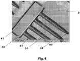
- the partial cutting is illustrated in a clear way in steps (a2(iv)) where the connector part 42 is attached to the substrate 1 via an attachment point 40. Step (a3) is performed either everywhere or not everywhere (via appropriate masking of the first surface) in order to maintain attachment points 40.
- the partial cutting of the probe is illustrated as seen from the second surface of the substrate.
- at least one attachment point 40 between the connector part 42 and the substrate 1 remains after the partial etching and thus cutting of the first surface.
- the attachment point 40 is easily released from the rest of the substrate.
- using tweezers to release the probe from the substrate can be easily performed.
- no additional dicing is required to separate the probes fro the fabrication wafer.
- An advantage of a method in accordance with embodiments of the present invention is that it offers a solution for drastically reducing the cross-sectional area of a probe without compromising the resistance of the probe to bending, buckling or flexing. As a result of this drastically reduced cross-section the amount of damage the probe inflicts to the biological tissue is as low as possible. However, when making the probes too thin other problems such as increased fragility, flexing or buckling can occur during the insertion phase of the probe.
- the T-shaped cross-section additionally provides reinforcement of the probe in order to overcome these problems.
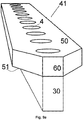
- a probe 32 for brain recording or stimulation comprises a T-shaped profile and the T-shape is defined by a horizontal part 31 and a vertical part 30, wherein the horizontal part has a first surface 50 and a second surface 51, wherein said vertical part 30 is attached to said second surface 51, and wherein said first surface 50 comprises one or more electrodes (recording/ stimulating sites) 4.
- the probe according to any embodiments has a sharp distal end and has a stiffness that is sufficient for allowing insertion of the probe into a brain. More specifically the probe can be inserted in the brain without deflection.
- Another embodiment of the present invention relates to a method of fabricating a probe for brain recording or stimulation, whereby the probe has shanks having a H-shaped cross-section defined by a vertical part and two horizontal parts.
- the method comprises the steps of attaching the free extremity of the vertical part of a shank according to anyone of the previous embodiments with either a further horizontal part or the free extremity of a vertical part of a second shaft according to anyone of the previous embodiments.
- An advantage of using a probe with H-shaped cross-section shanks is that it doubles the amount of electrodes that can be used: the electrodes on the first surface of the first and second horizontal parts of the H-shaped cross-sectioned shanks.
- the attaching of the free extremities of the vertical part of both shanks can be enabled by glue or anodic bonding. Any glue suitable for attaching electronic components can be used. Before applying the glue the free extremities are preferably cleaned.
- FIG. 1 schematically illustrates a probe 32 for brain recording and/or stimulation according to an embodiment of the present invention. It comprises four shanks 41 and a connector part 42. From the connector part 42, each shank 41 protrudes along a same orientation.
- the shank 41 comprises a first side 50 and a second side 51 opposite to the first side.
- the first side 50 of the shank 41 comprises a number of recording and/or stimulating sites 4 that are connected to a signal processing circuitry.
- the second side 51 of the shank comprises a fin 30, protruding perpendicularly from the second side 51 and running on a major part of the shank 41 along the same orientation as the shank.
- the thickness of the elongate shaft portions and the triangular chisel-shaped tip portion is essentially constant.
- the probe has a first and second flat surface, the thickness of the probes extending between said surfaces.
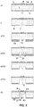
- Figure 2 is a schematic representation of a manufacturing method viewed orthogonally to the probe shank 41 through one recording and/or stimulating site 4, according to an embodiment of the present invention.
- the method comprises a step (a1) of providing a substrate 1 having a first 2 and a second 3 surface, whereby the first surface 2 comprises at least one recording and/or stimulating site 4.
- a first etch mask pattern 10 is provided on the second surface 3, and the first etch mask pattern 10 masks the area corresponding to the fin 30 of the shank 41.
- step (a2(ii)) dry-etching of the second surface 3 is performed in a direction 9 perpendicular to the second surface 3 in such a way as thinning, but not eliminating, at least part of said substrate 1 away from the first etch mask pattern 10, thereby defining the height 12 of the fin 30 of the shank 41.
- the first etch mask pattern 10 is resistant to the dry-etching process performed in step (a2(iii)).
- a passivation layer 5 is provided before performing the first step (a1).
- an etch mask layer 11 and an isolation layer 14 on respectively the second surface 3 and the first surface 2 of the substrate 1 can be applied.
- the substrate material used is preferably a semiconductor and more specifically silicon.
- the recording and/or stimulating sites 4 can be deposited using several deposition techniques known in the prior art, such as for example electron beam deposition, sputtering or plasma vapour deposition or any other conventional thin film deposition technique.
- the method may further comprise a step (s) after step (a1) and before step (a2(ii)), whereby a second etch mask pattern 8 is provided on the second surface 3, delimiting the shape of the shanks 41 of the probe 32 to be fabricated.
- the second etch mask pattern 8 can be created by patterning the etch mask layer 11 covering the second surface 3 in such a way as to create an opening 7 in the layer, whereby the opening 7 preferably comprises the masking area corresponding to the fin 30 of the probe 32.
- step (s) is performed before step (a2(i)).
- at least part of the masking area 8 corresponds to the connector part 42 of the probe 32.
- the second etch mask pattern 8 is resistant to a dry-etching process.
- dry-etching techniques can be applied for fabricating the probe according to any embodiments of the invention, for instance Xenon difluoride etching, reactive ion etching or deep reactive ion etching.
- Preferably deep reactive ion etching is used to etch away parts of the substrate 1.
- etch depths of hundreds of micrometers are achieved with almost vertical sidewalls.
- the primary technology is based on the so-called patented "Bosch process" ( FR 2948495 ). The process can easily be used to etch completely through a silicon substrate, and etch rates are 3-6 times higher than wet etching.
- the method further can comprise after step (a2(ii)), a step (a2(iii)) whereby the first etch mask pattern 10 is removed without removing the second etch mask pattern 8, and then in step ((a2(iv)) dry-etching of the second surface 3 is performed in a direction perpendicular 9 to the second surface 3.
- step (a2(iv)) dry-etching of the second surface 3 is performed in a direction perpendicular 9 to the second surface 3.
- the substrate is thinned but not eliminated, thereby defining the thickness 13 of the horizontal part 31 of the shank 41 having T-shaped cross-section, and thus also defining the thickness of the shank 41.
- the probe 32 is partially cut out the substrate 1, thereby providing said probe 32.
- the partial cutting of the probe 32 can be achieved by dry-etching the first surface 2 of the substrate 1 after patterning of an isolation layer 14 and the passivation layer 5 on the first surface 2 of the substrate 1.
- the partial cutting is illustrated in a clear way in steps (a2(iv)) and (a3).
- step (a2(iv)) the connector part 42 is attached to the substrate and the shanks 41 are fabricated.
- the cutting is performed in step (a3) and looking along the probe shank 41 the probe is completely cut out.
- the partial cutting of the probe is illustrated as seen from the second surface 3 of the substrate 1.
- at least one attachment point 40 between the connector part 42 and the substrate 1 remains after the partial etching and thus cutting of the first surface.
- the attachment point 40 is easily released from its coupled state. For instance, using tweezers to release the probe from the substrate can be easily performed.
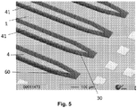
- Figure 5 illustrates the shanks 41 have a T-shaped cross-section, whereby the fin 30 defines the vertical part of the T-shaped cross-section.
- the distal end 60 of the shanks 41 are preferably sharpen as an additional step (b) after step (a3) according to some embodiments of the invention.
- Fig. 6 shows an enlarged picture of the fin 30 of a shank 41 seen on second side 51 of the shank.
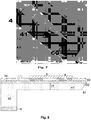
- Fig. 7 shows an enlarged picture of the distal end 60 of a shank 41 comprising recording and/or stimulating sites 4.
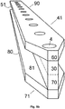
- Fig. 9a is a schematic representation of a T-shaped probe shank 41 and Fig. 9b offers a schematic representation of an H-shaped probe shank 90.
- the H-shaped probe shank 90 is constructed by attaching the free extremity of the fin 30 of a shank 41 of a first probe to the fin 70 of a shank 71 of a second probe having a first side 80 and second side 81 that is opposed to the first side.
- the first side 80 of the second shank 71 comprises at least one recording and/or stimulating sites (not shown).
- an H-shaped probe shank 90 can be constructed by attaching the free extremity of the fin 30 of a shank 41 directly to the second side 81 of a second shank 71 comprising no fin 70, whereby the first side of this second shank 71 may comprise recording and/or stimulating sites 4.
- the sharpening of the distal end 60 can be performed by grinding the second side 51 of the shank.
- the height of the horizontal part 13 of the T-shaped cross-section is not uniform throughout the shank length L.
- the thickness D2 of the horizontal part of the T-shaped cross-section 31 at the distal end 60 is smaller than the thickness D1 of the horizontal part of the T-shaped cross-section at a point on the shank 41 away from the distal end 60.
- the second side 51 of the shank 41 comprising the distal end 60 makes an angle 61 with the second side of the shank 41 away from the distal end 60. This angle is smaller than 90° and is preferably smaller than 65°.
- the tip present at the distal end 60 lies in the plane defined by the probe's first side.
- the grinding of the distal end 60 can be performed by temporary fixing the unsharpened probe 32 on a carrier 110 (see Fig. 11 ), which is sloped under an angle, in such a way that the second side 51 of the shank 41 comprising the distal end of the probe 32 is leading over the carrier 110.
- the carrier 110 then can be positioned on a rotating polishing disk 120 (see Fig. 13 ) which grinds the second side 51 of the shank 41 comprising the distal end 60.
- the carrier 110 with probe 32 can be positioned on a polishing table e.g. for several minutes resulting in a sharp pointy tip.
- the above mentioned angle 61 is determined by the angle of the sloped carrier 110 used for grinding.
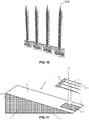
- FIG 10 shows a neural probe obtainable by the method of the invention.
- Each shank has a sharp pointed tip 101, able to pierce through the Dura without the dimpling effect.
- the fin is not represented but is present.
- a probe 32 is provided having an essentially constant thickness of the elongate shank 41 and the triangular chisel-shaped tip portions at the distal end, i.e. the probe has a first and second flat side 50/51, the thickness of the shanks extending between said sides.
- the probe is temporarily attached (e.g. by its fin(s)) at said second side 51, to a carrier 110, which is preferably a solid carrier block, e.g. made of aluminum.
- the carrier block shown in figure 11 is wedge-shaped, with a flat base surface 111 and a slanted top surface 112, forming a sharp angle with respect to the base surface, so that a straight edge 113 is formed between the base and top surfaces 111 and 112.
- the carrier 110 further comprises parallel side walls 114 and a back wall 115 perpendicular to the base surface.
- Other outer shapes of the carrier are possible, as long as the carrier comprises a first and second surface 111/112 forming a wedge, i.e. being oriented at a sharp angle with respect to each other, and joined by an edge 113 of the carrier.
- the probe 32 is releasably attached to a contact location 116 of the carrier's slanted top surface 112, with at least part of the triangular tip portions at the distal end 60 extending over the edge 113, all triangular tip portions being placed at the same distance from the edge 113.
- a portion of the shanks extends downward from the base surface 111 when said base surface is placed horizontally (see figure 12 ).
- the connector part 42 and shanks 41 of the probe 32 are removably attached to the top surface 112 of the carrier block 110 with a suitable temporary adhesive, e.g. a resin or a wax.
- the contact location 116 on the slanted surface 112 of the block may be provided with an alignment structure, preferably comprising a set of grooves oriented perpendicularly to the edge 113, and at a mutual distance corresponding to the mutual distance of the probes in the array, so that the probes fit into said grooves. More preferably, the alignment structure is a negative imprint of the entire probe array, including the connector part 42, so that the entire probe 32 can be fitted into the carrier block's top surface 112.
- the above named adhesive is preferably used in addition to the alignment structure. Extending outward from the carrier edge 113 is the straight edge 100 of the chisel-shaped triangular probe tips at the distal end 60.
- the straight edge 100 is essentially perpendicular to the surface 112 of the carrier.
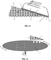
- the carrier block/probe combination is subjected to a grinding step as illustrated in figure 13 .
- a known grinding/polishing tool is used, having a rotating grinding disc 120 onto which the carrier block 110 can be placed with a suitable pressure.
- the carrier block can be fixed onto a micro-drive which lowers the carrier onto the rotating grinding/polishing disk.
- Suitable grinding/polishing tools that can be used are the Saphir 320/330 series from ATM.
- the carrier material, the material of the grinding surface, the applied pressure and grinding time are chosen so that substantially no or very little material is removed from the carrier block's base surface 111 during said grinding step, while all the material of the probe tips extending below the base surface 111 is removed during said step.
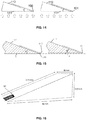
- the result of the grinding step is shown in figure 14 .
- the portion of the probes extending below the base surface 111 is removed, and a sharp tip 101 is formed at the distal end of the probes.
- the angle ⁇ of the carrier block 110 is thereby substantially transferred to the probe tips.
- FIG. 15 Another embodiment is illustrated in figure 15 .
- the material of the carrier 110, the material of the grinding surface, the grinding pressure and time are chosen so that the carrier block's base surface 111 is thinned during the grinding step, together with the shank tip.
- the shanks are attached to the carrier block without the triangular tip portions at the distal end 60 extending over the edge 113, preferably with the lower end 121 of the tip placed on the edge 113, as shown in figure 15 .
- a thickness 'a' of the carrier block and of the tip material is simultaneously removed, leading also to a sharp tip 101 at the end of the grinding step, with the angle ⁇ of the carrier block transferred to the shank tip.
- the tip 101 lies in the plane defined by the probe's first side 50.
- the edge 113 may be curved instead of straight. This allows the formation of shank tips of different shape and size in one grinding step. Likewise, instead of placing the shanks of a probe at the same distance to a straight edge 113, it is possible to place the probe at an angle to the edge. Instead of an array of shanks, a single shank may be sharpened by the method of the invention.
- the angle ⁇ is a sharp angle, i.e. lower than 90°, but preferably lower than 45°.
- the carrier 110 is preferably but not necessarily a solid block.
- the grinding step can be followed by a polishing step, which may release the stresses induced by the grinding process.
- the polishing step can be performed in the same tool as the grinding step, e.g. by applying another polishing disk onto the rotating table of a rotatable grinding tool.
- the probe is attached by its fin 30 (not shown) to the carrier block 110 as described above and a portion of the tip is removed by grinding and possibly polishing, preferably until at least about half of the straight edge 100 is removed.
- the probe is removed, reversed and re-attached by its first side 50, and a second grinding and possibly polishing step is done until a sharp tip is obtained, said tip lying in between the first and second side 50/51 of the probe. Both steps can be done by the method of the invention according to the embodiment of figure 14 or 15 .
- the sharpness of the carrier's edge 113 is not a crucial parameter. It is possible to grind the tip of the probe while the carrier contains a blunt edge 113. Since the angle of the carrier 110 and the thickness of the tip is known, one can calculate how far the chisel shaped tip at the distal end should extend from the edge 113.
- an insulating layer (14, 11) is deposited on both wafer sides (2, 3).
- the layer (14, 11) is a stress compensated stack of a thermal silicon dioxide (SiO 2 ) grown at 950 °C, a silicon nitride (Si 3 N 4 ) produced by low-pressure chemical vapor deposition (LPCVD) at 770 °C and a LPCVD low temperature oxide (LTO) deposited at 425 °C.
- the corresponding thicknesses are 200 nm, 100 nm and 200 nm.
- the stress compensation of the different layer stacks is based on residual stress values.
- the electrode metallization 4 consists of 30 nm titanium (Ti), 200 nm gold (Au), 100 nm platinum (Pt) and 30 nm Ti. These layers are deposited by evaporation and patterned using a lift-off process. The evaporation of the metals was performed in a static deposition mode with the wafer position fixed above the evaporation source. By this choice frayed metal edges are avoided. In contrast, in the alternative dynamic mode, where up to six wafers are rotated above crucibles, negatively tapered resist sidewalls are partly covered due to an increased angle of incidence. While titanium serves as the adhesion layer to the dielectric thin films, gold is used to minimize the interconnection resistance and platinum is the electrode material of choice.
- the metal stack is covered by a 1.5 ⁇ m thick passivation multilayer 5.
- This is again a stress compensated layer stack of alternating PECVD SiO x (210 nm) and SixNy (160 nm) thin films.
- the passivation is patterned by reactive ion etching (RIE) using the STS RIE Multiplex etcher of Surface Technology Systems, UK, thus opening electrodes and contact pads, as indicated in figure 2 and 3 , step a1.
- RIE reactive ion etching
- CF 4 tetrafluoromethane
- CHF 3 fluoroform
- argon argon
- the rear SiOx/SixNy etch masks 11 are patterned using RIE, as shown in figure 2 and 3 (s).
- a photoresist layer 10 is spin coated on the rear of the wafer to define the step of the T-shape, as shown in figure 2 a2(i).
- the first DRIE step using an STS ICP Multiplexetcher from Surface Technology Systems, UK etches the T-shape step, as shown in figure 2 a2(ii).
- the photoresist 10 is removed, as shown in figure 2 and 3 a2(iii) and the second DRIE 9 is applied, which defines the overall geometry of the shaft thickness (also using an STS ICP Multiplexetcher from Surface Technology Systems, UK), see figure a2 (iv).
- the final DRIE step 9 is performed from the wafer front prior front side patterning of the SiOx/SixNy passivation layer 5 (using RIE) to complete the release of the probes, as shown in figure 2 and 3 (a3).
- the fabrication wafer with probes suspended by a pair of thin struts is finally separated from the support wafer.
Landscapes
- Health & Medical Sciences (AREA)
- Neurology (AREA)
- Neurosurgery (AREA)
- Psychology (AREA)
- Cardiology (AREA)
- Heart & Thoracic Surgery (AREA)
- Engineering & Computer Science (AREA)
- Biomedical Technology (AREA)
- Nuclear Medicine, Radiotherapy & Molecular Imaging (AREA)
- Radiology & Medical Imaging (AREA)
- Life Sciences & Earth Sciences (AREA)
- Animal Behavior & Ethology (AREA)
- General Health & Medical Sciences (AREA)
- Public Health (AREA)
- Veterinary Medicine (AREA)
- Electrotherapy Devices (AREA)
Claims (12)
- Sonde (32) zur Hirnaufzeichnung und/oder -stimulation, wobei die Sonde (32) einen oder mehrere Schenkel (41) umfasst, welche die gleiche Ausrichtung aufweisen, wobei jeder der Schenkel (41) eine erste Seite (50) und eine zweite, der ersten Seite (50) entgegengesetzte Seite (51) aufweist und an der ersten Seite (50) mindestens eine Aufzeichnungs- und/oder Stimulationsstelle (4) umfasst,
wobei jeder der Schenkel (41) ferner eine Rippe (30) umfasst, die senkrecht von der zweiten Seite (51) hervorsteht und auf mindestens einem Teil der Länge des Schenkels (41) in der gleichen Ausrichtung verläuft, wobei jeder der Schenkel (41) an seinem distalen Ende (60) eine scharf zulaufende Spitze aufweist,
dadurch gekennzeichnet, dass die Spitze in der Ebene liegt, die durch die erste Seite (50) definiert ist. - Sonde (32) nach Anspruch 1, wobei die Schenkel einen T-förmigen Querschnitt aufweisen, der durch die Rippe (30) bereitgestellt wird, die senkrecht von der zweiten Seite (51) hervorsteht.
- Sonde (32) nach Anspruch 1 oder 2, wobei die erste Seite (50) an dem distalen Ende (60) des Schenkels (41) und weg von dem distalen Ende (60) eine gleiche Ausrichtung aufweist, wohingegen die zweite Seite (51) an dem distalen Ende (60) weg von dem distalen Ende (60) einen Winkel (61) zur zweiten Seite (51) beschreibt.
- Sonde (32) nach einem der vorhergehenden Ansprüche, wobei die Spitze eine Dreieckform aufweist.
- Sonde (32) nach einem der vorhergehenden Ansprüche, wobei die Spitze eine Meißelform aufweist.
- Sonde (32) nach einem der vorhergehenden Ansprüche, ferner mindestens einen zweiten Schenkel (71) umfassend, wobei die Rippe (30) angebracht ist an entweder:a) einer Rippe (70) des zweiten Schenkels (71), wobei der zweite Schenkel (71) eine erste Seite (80) und eine zweite, der ersten Seite (80) entgegengesetzte Seite (81) aufweist und an der ersten Seite (80) mindestens eine Aufzeichnungs- und/oder Stimulationsstelle umfasst und die Rippe (70) senkrecht von der zweiten Seite (81) hervorsteht und auf mindestens einem Teil der Länge des zweiten Schenkels (71) in der gleichen Ausrichtung verläuft, oderb) der zweiten Seite (81) des zweiten Schenkels (71), der eine erste Seite (80) und eine zweite, der ersten Seite (80) entgegengesetzte Seite (81) aufweist und an der ersten Seite (80) mindestens eine Aufzeichnungs- und/oder Stimulationsstelle (4) umfasst, oderc) der zweiten Seite (81) des zweiten Schenkels (71), der eine erste Seite (80) und eine zweite, der ersten Seite (80) entgegengesetzte Seite (81) aufweist.
- Verfahren zur Herstellung einer Sonde (32) zur Hirnaufzeichnung und/oder -stimulation, wobei die Sonde (32) nach einem der Ansprüche 1 bis 6 einen oder mehrere Schenkel (41) umfasst, welche die gleiche Ausrichtung aufweisen, wobei das Verfahren folgende Schritte umfasst: Bereitstellen einer Sonde (32) zur Hirnaufzeichnung und/oder -stimulation, wobei die Sonde (32) einen oder mehrere Schenkel (41) umfasst, welche die gleiche Ausrichtung aufweisen, wobei jeder der Schenkel (41) eine erste Seite (50) und eine zweite, der ersten Seite (50) entgegengesetzte Seite (51) aufweist und an der ersten Seite (50) mindestens eine Aufzeichnungs- und/oder Stimulationsstelle (4) umfasst, und eine Rippe (30), die senkrecht von der zweiten Seite (51) hervorsteht und auf mindestens einem Teil der Länge des Schenkels (41) in der gleichen Richtung verläuft; und
wobei das Bereitstellen der Sonde folgende Schritte umfasst:a1) Bereitstellen eines Substrats (1) mit einer ersten Oberfläche (2) und einer zweiten, der ersten Oberfläche (2) entgegengesetzten Oberfläche (3), wobei die erste Oberfläche (2) mindestens eine Aufzeichnungs- und/oder Stimulationsstelle (4) jedes des einen oder der mehreren Schenkel (41) der herzustellenden Sonde (32) umfasst,a2) (i) Bereitstellen einer ersten Ätzmaskenstruktur (10) auf der zweiten Oberfläche (3), wobei die erste Ätzmaskenstruktur (10) den Bereich maskiert, welcher der Rippe (30) jedes des einen oder der mehreren Schenkel (41) der herzustellenden Sonde (32) entspricht, wobei die erste Ätzmaskenstruktur (10) beständig gegen einen Trockenätzprozess ist, und
(ii) Trockenätzen der zweiten Oberfläche (3) in einem Trockenätzprozess, gegen den die erste Ätzmaskenstruktur (10) beständig ist, in einer Richtung (9) senkrecht zur zweiten Oberfläche (3) derart, dass zumindest ein Teil des Substrats (1) weg von der ersten Ätzmaskenstruktur (10) ausgedünnt, aber nicht beseitigt wird, wodurch die Höhe der Rippen (30) definiert wird,b) Schärfen eines distalen Endes (60) der Schenkel (41) derart, dass die Schenkel mit einer scharf zulaufenden Spitze an ihrem distalen Ende (60) bereitgestellt werden,dadurch gekennzeichnet, dass die Spitze in der Ebene liegt, die durch die erste Seite (50) definiert wird. - Verfahren nach Anspruch 7, wobei die erzielte Sonde (32) (einen) Schenkel (41) mit T-förmigem Querschnitt aufweist.
- Verfahren nach Anspruch 7 oder 8, wobei die Sonde (32) ferner einen Anschlussteil (42) umfasst, von dem aus der eine oder die mehreren Schenkel (41) in dergleichen Richtung hervorstehen und wobei in Schritt (a2 (i)) die erste Ätzmaskenstruktur (10) ferner den Bereich maskiert, der dem Anschlussteil (42) der herzustellenden Sonde (32) entspricht.
- Verfahren nach einem der Ansprüche 7 bis 9, wobei die erste Ätzmaskenstruktur (10) genau den Bereich maskiert, welcher der Rippe (30) jedes des einen oder der mehreren Schenkel (41) der herzustellenden Sonde (32) entspricht.
- Verfahren nach einem der Ansprüche 7 bis 10, nach Schritt (a1) und vor Schritt (a2 (ii)) ferner einen Schritt (s) des Bereitstellens einer zweiten Ätzmaskenstruktur (8) auf der zweiten Oberfläche (3) umfassend, welche die Form der Schenkel (41) der zu fertigenden Sonde (32) begrenzt, wobei die zweite Ätzmaskenstruktur (8) beständig gegen einen Trockenätzprozess ist.
- Verfahren nach Anspruch 11, wobei der Schritt (s) vor Schritt (a2 (i)) ausgeführt wird.
Priority Applications (1)
| Application Number | Priority Date | Filing Date | Title |
|---|---|---|---|
| EP11181696.3A EP2570152B1 (de) | 2011-09-16 | 2011-09-16 | Strukturierte Sonden für neurale Anwendungen |
Applications Claiming Priority (1)
| Application Number | Priority Date | Filing Date | Title |
|---|---|---|---|
| EP11181696.3A EP2570152B1 (de) | 2011-09-16 | 2011-09-16 | Strukturierte Sonden für neurale Anwendungen |
Publications (2)
| Publication Number | Publication Date |
|---|---|
| EP2570152A1 EP2570152A1 (de) | 2013-03-20 |
| EP2570152B1 true EP2570152B1 (de) | 2018-08-22 |
Family
ID=44773998
Family Applications (1)
| Application Number | Title | Priority Date | Filing Date |
|---|---|---|---|
| EP11181696.3A Active EP2570152B1 (de) | 2011-09-16 | 2011-09-16 | Strukturierte Sonden für neurale Anwendungen |
Country Status (1)
| Country | Link |
|---|---|
| EP (1) | EP2570152B1 (de) |
Citations (1)
| Publication number | Priority date | Publication date | Assignee | Title |
|---|---|---|---|---|
| US20100331935A1 (en) * | 2009-05-01 | 2010-12-30 | Phillipe Tabada | Rigid Spine Reinforced Polymer Microelectrode Array Probe and Method of Fabrication |
Family Cites Families (5)
| Publication number | Priority date | Publication date | Assignee | Title |
|---|---|---|---|---|
| US5591139A (en) | 1994-06-06 | 1997-01-07 | The Regents Of The University Of California | IC-processed microneedles |
| FR2918285A1 (fr) | 2007-07-03 | 2009-01-09 | Commissariat Energie Atomique | Sonde a electrodes multiples et systeme pour neurostimulation electrique profonde comportant une telle sonde |
| DE102009028037A1 (de) | 2009-07-27 | 2011-02-03 | Robert Bosch Gmbh | Bauelement mit einer elektrischen Durchkontaktierung, Verfahren zur Herstellung eines Bauelementes und Bauelementsystem |
| CA2782710C (en) * | 2009-12-01 | 2019-01-22 | Ecole Polytechnique Federale De Lausanne | Microfabricated neurostimulation device and methods of making and using the same |
| DE102010000565A1 (de) * | 2010-02-26 | 2011-09-01 | Technische Universität Ilmenau | Hybrides dreidimensionales Sensorarray, insbesondere zur Vermessung elektrogener Zellanordnungen, sowie Messanordnung |
-
2011
- 2011-09-16 EP EP11181696.3A patent/EP2570152B1/de active Active
Patent Citations (1)
| Publication number | Priority date | Publication date | Assignee | Title |
|---|---|---|---|---|
| US20100331935A1 (en) * | 2009-05-01 | 2010-12-30 | Phillipe Tabada | Rigid Spine Reinforced Polymer Microelectrode Array Probe and Method of Fabrication |
Also Published As
| Publication number | Publication date |
|---|---|
| EP2570152A1 (de) | 2013-03-20 |
Similar Documents
| Publication | Publication Date | Title |
|---|---|---|
| US20130072808A1 (en) | Structured probes for neural applications | |
| US8499673B2 (en) | Microsurgical cutting instruments | |
| US6187210B1 (en) | Epidermal abrasion device with isotropically etched tips, and method of fabricating such a device | |
| US5842387A (en) | Knife blades having ultra-sharp cutting edges and methods of fabrication | |
| US7992309B2 (en) | Micromachined cutting blade formed from {211}-oriented silicon | |
| US20090093776A1 (en) | 3d solid or hollow silicon microneedle and microknife with "-" shape structure | |
| US7963042B2 (en) | Micro surgical cutting instruments | |
| US7124511B2 (en) | Razor blade | |
| EP3895861A1 (de) | Rasiervorrichtung | |
| US6610235B1 (en) | Method of fabricating epidermal abrasion device | |
| US20020078576A1 (en) | Micromachined surgical scalpel | |
| EP2570152B1 (de) | Strukturierte Sonden für neurale Anwendungen | |
| FI3900064T3 (en) | METHOD FOR TRANSFERRING SURFACE LAYER OVER CAVITIES | |
| US20070128875A1 (en) | Dry etch release method for micro-electro-mechanical systems (MEMS) | |
| JP2003115536A (ja) | ウェーハアセンブリ内の半導体構成要素およびその製造方法 | |
| US20190366068A1 (en) | Microneedle for biosensing and method of fabrication | |
| RU2346800C2 (ru) | Способ изготовления микрохирургических лезвий | |
| EP3210935A1 (de) | Verfahren zur herstellung einer vielzahl von durchgangslöchern in einer materialschicht | |
| US20230174372A1 (en) | Method for manufacturing implantable electrodes and electrodes made by such methods | |
| NL2026676B1 (en) | A method of manufacturing a micro-fluidic probe | |
| JP2022528781A (ja) | ピラミッド状突起を含むmemsデバイスを提供する方法、及び型 | |
| TW202408430A (zh) | 高縱橫比微針及工具之製造方法 | |
| WO2005016151A1 (en) | Micromachined cutting blade formed from (211)-oriented silicon | |
| WO1997018912A1 (en) | Knifes blades having ultra-sharp cutting edges and methods of fabrication | |
| JPH0398234A (ja) | 単結晶シリコン電子放出銃アレイ及びその製造方法 |
Legal Events
| Date | Code | Title | Description |
|---|---|---|---|
| PUAI | Public reference made under article 153(3) epc to a published international application that has entered the european phase |
Free format text: ORIGINAL CODE: 0009012 |
|
| AK | Designated contracting states |
Kind code of ref document: A1 Designated state(s): AL AT BE BG CH CY CZ DE DK EE ES FI FR GB GR HR HU IE IS IT LI LT LU LV MC MK MT NL NO PL PT RO RS SE SI SK SM TR |
|
| AX | Request for extension of the european patent |
Extension state: BA ME |
|
| 17P | Request for examination filed |
Effective date: 20130911 |
|
| RBV | Designated contracting states (corrected) |
Designated state(s): AL AT BE BG CH CY CZ DE DK EE ES FI FR GB GR HR HU IE IS IT LI LT LU LV MC MK MT NL NO PL PT RO RS SE SI SK SM TR |
|
| RAP1 | Party data changed (applicant data changed or rights of an application transferred) |
Owner name: ALBERT-LUDWIGS-UNIVERSITAET FREIBURG Owner name: IMEC |
|
| STAA | Information on the status of an ep patent application or granted ep patent |
Free format text: STATUS: EXAMINATION IS IN PROGRESS |
|
| 17Q | First examination report despatched |
Effective date: 20170413 |
|
| RAP1 | Party data changed (applicant data changed or rights of an application transferred) |
Owner name: ALBERT-LUDWIGS-UNIVERSITAET FREIBURG Owner name: IMEC VZW |
|
| GRAP | Despatch of communication of intention to grant a patent |
Free format text: ORIGINAL CODE: EPIDOSNIGR1 |
|
| STAA | Information on the status of an ep patent application or granted ep patent |
Free format text: STATUS: GRANT OF PATENT IS INTENDED |
|
| INTG | Intention to grant announced |
Effective date: 20180425 |
|
| GRAS | Grant fee paid |
Free format text: ORIGINAL CODE: EPIDOSNIGR3 |
|
| GRAA | (expected) grant |
Free format text: ORIGINAL CODE: 0009210 |
|
| STAA | Information on the status of an ep patent application or granted ep patent |
Free format text: STATUS: THE PATENT HAS BEEN GRANTED |
|
| AK | Designated contracting states |
Kind code of ref document: B1 Designated state(s): AL AT BE BG CH CY CZ DE DK EE ES FI FR GB GR HR HU IE IS IT LI LT LU LV MC MK MT NL NO PL PT RO RS SE SI SK SM TR |
|
| REG | Reference to a national code |
Ref country code: GB Ref legal event code: FG4D |
|
| REG | Reference to a national code |
Ref country code: CH Ref legal event code: EP |
|
| REG | Reference to a national code |
Ref country code: AT Ref legal event code: REF Ref document number: 1031761 Country of ref document: AT Kind code of ref document: T Effective date: 20180915 |
|
| REG | Reference to a national code |
Ref country code: IE Ref legal event code: FG4D |
|
| REG | Reference to a national code |
Ref country code: DE Ref legal event code: R096 Ref document number: 602011051242 Country of ref document: DE |
|
| REG | Reference to a national code |
Ref country code: FR Ref legal event code: PLFP Year of fee payment: 8 |
|
| REG | Reference to a national code |
Ref country code: NL Ref legal event code: MP Effective date: 20180822 |
|
| REG | Reference to a national code |
Ref country code: LT Ref legal event code: MG4D |
|
| PG25 | Lapsed in a contracting state [announced via postgrant information from national office to epo] |
Ref country code: FI Free format text: LAPSE BECAUSE OF FAILURE TO SUBMIT A TRANSLATION OF THE DESCRIPTION OR TO PAY THE FEE WITHIN THE PRESCRIBED TIME-LIMIT Effective date: 20180822 Ref country code: SE Free format text: LAPSE BECAUSE OF FAILURE TO SUBMIT A TRANSLATION OF THE DESCRIPTION OR TO PAY THE FEE WITHIN THE PRESCRIBED TIME-LIMIT Effective date: 20180822 Ref country code: NO Free format text: LAPSE BECAUSE OF FAILURE TO SUBMIT A TRANSLATION OF THE DESCRIPTION OR TO PAY THE FEE WITHIN THE PRESCRIBED TIME-LIMIT Effective date: 20181122 Ref country code: BG Free format text: LAPSE BECAUSE OF FAILURE TO SUBMIT A TRANSLATION OF THE DESCRIPTION OR TO PAY THE FEE WITHIN THE PRESCRIBED TIME-LIMIT Effective date: 20181122 Ref country code: NL Free format text: LAPSE BECAUSE OF FAILURE TO SUBMIT A TRANSLATION OF THE DESCRIPTION OR TO PAY THE FEE WITHIN THE PRESCRIBED TIME-LIMIT Effective date: 20180822 Ref country code: GR Free format text: LAPSE BECAUSE OF FAILURE TO SUBMIT A TRANSLATION OF THE DESCRIPTION OR TO PAY THE FEE WITHIN THE PRESCRIBED TIME-LIMIT Effective date: 20181123 Ref country code: RS Free format text: LAPSE BECAUSE OF FAILURE TO SUBMIT A TRANSLATION OF THE DESCRIPTION OR TO PAY THE FEE WITHIN THE PRESCRIBED TIME-LIMIT Effective date: 20180822 Ref country code: LT Free format text: LAPSE BECAUSE OF FAILURE TO SUBMIT A TRANSLATION OF THE DESCRIPTION OR TO PAY THE FEE WITHIN THE PRESCRIBED TIME-LIMIT Effective date: 20180822 Ref country code: IS Free format text: LAPSE BECAUSE OF FAILURE TO SUBMIT A TRANSLATION OF THE DESCRIPTION OR TO PAY THE FEE WITHIN THE PRESCRIBED TIME-LIMIT Effective date: 20181222 |
|
| REG | Reference to a national code |
Ref country code: AT Ref legal event code: MK05 Ref document number: 1031761 Country of ref document: AT Kind code of ref document: T Effective date: 20180822 |
|
| PG25 | Lapsed in a contracting state [announced via postgrant information from national office to epo] |
Ref country code: HR Free format text: LAPSE BECAUSE OF FAILURE TO SUBMIT A TRANSLATION OF THE DESCRIPTION OR TO PAY THE FEE WITHIN THE PRESCRIBED TIME-LIMIT Effective date: 20180822 Ref country code: LV Free format text: LAPSE BECAUSE OF FAILURE TO SUBMIT A TRANSLATION OF THE DESCRIPTION OR TO PAY THE FEE WITHIN THE PRESCRIBED TIME-LIMIT Effective date: 20180822 Ref country code: AL Free format text: LAPSE BECAUSE OF FAILURE TO SUBMIT A TRANSLATION OF THE DESCRIPTION OR TO PAY THE FEE WITHIN THE PRESCRIBED TIME-LIMIT Effective date: 20180822 |
|
| PG25 | Lapsed in a contracting state [announced via postgrant information from national office to epo] |
Ref country code: ES Free format text: LAPSE BECAUSE OF FAILURE TO SUBMIT A TRANSLATION OF THE DESCRIPTION OR TO PAY THE FEE WITHIN THE PRESCRIBED TIME-LIMIT Effective date: 20180822 Ref country code: AT Free format text: LAPSE BECAUSE OF FAILURE TO SUBMIT A TRANSLATION OF THE DESCRIPTION OR TO PAY THE FEE WITHIN THE PRESCRIBED TIME-LIMIT Effective date: 20180822 Ref country code: CZ Free format text: LAPSE BECAUSE OF FAILURE TO SUBMIT A TRANSLATION OF THE DESCRIPTION OR TO PAY THE FEE WITHIN THE PRESCRIBED TIME-LIMIT Effective date: 20180822 Ref country code: RO Free format text: LAPSE BECAUSE OF FAILURE TO SUBMIT A TRANSLATION OF THE DESCRIPTION OR TO PAY THE FEE WITHIN THE PRESCRIBED TIME-LIMIT Effective date: 20180822 Ref country code: EE Free format text: LAPSE BECAUSE OF FAILURE TO SUBMIT A TRANSLATION OF THE DESCRIPTION OR TO PAY THE FEE WITHIN THE PRESCRIBED TIME-LIMIT Effective date: 20180822 Ref country code: PL Free format text: LAPSE BECAUSE OF FAILURE TO SUBMIT A TRANSLATION OF THE DESCRIPTION OR TO PAY THE FEE WITHIN THE PRESCRIBED TIME-LIMIT Effective date: 20180822 Ref country code: IT Free format text: LAPSE BECAUSE OF FAILURE TO SUBMIT A TRANSLATION OF THE DESCRIPTION OR TO PAY THE FEE WITHIN THE PRESCRIBED TIME-LIMIT Effective date: 20180822 |
|
| REG | Reference to a national code |
Ref country code: CH Ref legal event code: PL |
|
| REG | Reference to a national code |
Ref country code: DE Ref legal event code: R097 Ref document number: 602011051242 Country of ref document: DE |
|
| PG25 | Lapsed in a contracting state [announced via postgrant information from national office to epo] |
Ref country code: DK Free format text: LAPSE BECAUSE OF FAILURE TO SUBMIT A TRANSLATION OF THE DESCRIPTION OR TO PAY THE FEE WITHIN THE PRESCRIBED TIME-LIMIT Effective date: 20180822 Ref country code: SK Free format text: LAPSE BECAUSE OF FAILURE TO SUBMIT A TRANSLATION OF THE DESCRIPTION OR TO PAY THE FEE WITHIN THE PRESCRIBED TIME-LIMIT Effective date: 20180822 Ref country code: SM Free format text: LAPSE BECAUSE OF FAILURE TO SUBMIT A TRANSLATION OF THE DESCRIPTION OR TO PAY THE FEE WITHIN THE PRESCRIBED TIME-LIMIT Effective date: 20180822 |
|
| REG | Reference to a national code |
Ref country code: BE Ref legal event code: MM Effective date: 20180930 |
|
| REG | Reference to a national code |
Ref country code: IE Ref legal event code: MM4A |
|
| PG25 | Lapsed in a contracting state [announced via postgrant information from national office to epo] |
Ref country code: MC Free format text: LAPSE BECAUSE OF FAILURE TO SUBMIT A TRANSLATION OF THE DESCRIPTION OR TO PAY THE FEE WITHIN THE PRESCRIBED TIME-LIMIT Effective date: 20180822 Ref country code: LU Free format text: LAPSE BECAUSE OF NON-PAYMENT OF DUE FEES Effective date: 20180916 |
|
| PLBE | No opposition filed within time limit |
Free format text: ORIGINAL CODE: 0009261 |
|
| STAA | Information on the status of an ep patent application or granted ep patent |
Free format text: STATUS: NO OPPOSITION FILED WITHIN TIME LIMIT |
|
| 26N | No opposition filed |
Effective date: 20190523 |
|
| PG25 | Lapsed in a contracting state [announced via postgrant information from national office to epo] |
Ref country code: IE Free format text: LAPSE BECAUSE OF NON-PAYMENT OF DUE FEES Effective date: 20180916 |
|
| PG25 | Lapsed in a contracting state [announced via postgrant information from national office to epo] |
Ref country code: LI Free format text: LAPSE BECAUSE OF NON-PAYMENT OF DUE FEES Effective date: 20180930 Ref country code: CH Free format text: LAPSE BECAUSE OF NON-PAYMENT OF DUE FEES Effective date: 20180930 Ref country code: SI Free format text: LAPSE BECAUSE OF FAILURE TO SUBMIT A TRANSLATION OF THE DESCRIPTION OR TO PAY THE FEE WITHIN THE PRESCRIBED TIME-LIMIT Effective date: 20180822 Ref country code: BE Free format text: LAPSE BECAUSE OF NON-PAYMENT OF DUE FEES Effective date: 20180930 |
|
| PG25 | Lapsed in a contracting state [announced via postgrant information from national office to epo] |
Ref country code: MT Free format text: LAPSE BECAUSE OF NON-PAYMENT OF DUE FEES Effective date: 20180916 |
|
| PG25 | Lapsed in a contracting state [announced via postgrant information from national office to epo] |
Ref country code: TR Free format text: LAPSE BECAUSE OF FAILURE TO SUBMIT A TRANSLATION OF THE DESCRIPTION OR TO PAY THE FEE WITHIN THE PRESCRIBED TIME-LIMIT Effective date: 20180822 |
|
| PG25 | Lapsed in a contracting state [announced via postgrant information from national office to epo] |
Ref country code: HU Free format text: LAPSE BECAUSE OF FAILURE TO SUBMIT A TRANSLATION OF THE DESCRIPTION OR TO PAY THE FEE WITHIN THE PRESCRIBED TIME-LIMIT; INVALID AB INITIO Effective date: 20110916 Ref country code: PT Free format text: LAPSE BECAUSE OF FAILURE TO SUBMIT A TRANSLATION OF THE DESCRIPTION OR TO PAY THE FEE WITHIN THE PRESCRIBED TIME-LIMIT Effective date: 20180822 |
|
| PG25 | Lapsed in a contracting state [announced via postgrant information from national office to epo] |
Ref country code: CY Free format text: LAPSE BECAUSE OF FAILURE TO SUBMIT A TRANSLATION OF THE DESCRIPTION OR TO PAY THE FEE WITHIN THE PRESCRIBED TIME-LIMIT Effective date: 20180822 Ref country code: MK Free format text: LAPSE BECAUSE OF NON-PAYMENT OF DUE FEES Effective date: 20180822 |
|
| P01 | Opt-out of the competence of the unified patent court (upc) registered |
Effective date: 20230513 |
|
| PGFP | Annual fee paid to national office [announced via postgrant information from national office to epo] |
Ref country code: GB Payment date: 20230823 Year of fee payment: 13 |
|
| PGFP | Annual fee paid to national office [announced via postgrant information from national office to epo] |
Ref country code: FR Payment date: 20230822 Year of fee payment: 13 Ref country code: DE Payment date: 20230822 Year of fee payment: 13 |