EP2569092B1 - Anordnung für lackierobjekte - Google Patents
Anordnung für lackierobjekte Download PDFInfo
- Publication number
- EP2569092B1 EP2569092B1 EP11725148.8A EP11725148A EP2569092B1 EP 2569092 B1 EP2569092 B1 EP 2569092B1 EP 11725148 A EP11725148 A EP 11725148A EP 2569092 B1 EP2569092 B1 EP 2569092B1
- Authority
- EP
- European Patent Office
- Prior art keywords
- paint
- air
- gas flow
- powder paint
- hot gas
- Prior art date
- Legal status (The legal status is an assumption and is not a legal conclusion. Google has not performed a legal analysis and makes no representation as to the accuracy of the status listed.)
- Active
Links
Images


Classifications
-
- B—PERFORMING OPERATIONS; TRANSPORTING
- B05—SPRAYING OR ATOMISING IN GENERAL; APPLYING FLUENT MATERIALS TO SURFACES, IN GENERAL
- B05B—SPRAYING APPARATUS; ATOMISING APPARATUS; NOZZLES
- B05B7/00—Spraying apparatus for discharge of liquids or other fluent materials from two or more sources, e.g. of liquid and air, of powder and gas
- B05B7/16—Spraying apparatus for discharge of liquids or other fluent materials from two or more sources, e.g. of liquid and air, of powder and gas incorporating means for heating or cooling the material to be sprayed
- B05B7/1606—Spraying apparatus for discharge of liquids or other fluent materials from two or more sources, e.g. of liquid and air, of powder and gas incorporating means for heating or cooling the material to be sprayed the spraying of the material involving the use of an atomising fluid, e.g. air
- B05B7/1613—Spraying apparatus for discharge of liquids or other fluent materials from two or more sources, e.g. of liquid and air, of powder and gas incorporating means for heating or cooling the material to be sprayed the spraying of the material involving the use of an atomising fluid, e.g. air comprising means for heating the atomising fluid before mixing with the material to be sprayed
- B05B7/162—Spraying apparatus for discharge of liquids or other fluent materials from two or more sources, e.g. of liquid and air, of powder and gas incorporating means for heating or cooling the material to be sprayed the spraying of the material involving the use of an atomising fluid, e.g. air comprising means for heating the atomising fluid before mixing with the material to be sprayed and heat being transferred from the atomising fluid to the material to be sprayed
- B05B7/1626—Spraying apparatus for discharge of liquids or other fluent materials from two or more sources, e.g. of liquid and air, of powder and gas incorporating means for heating or cooling the material to be sprayed the spraying of the material involving the use of an atomising fluid, e.g. air comprising means for heating the atomising fluid before mixing with the material to be sprayed and heat being transferred from the atomising fluid to the material to be sprayed at the moment of mixing
-
- B—PERFORMING OPERATIONS; TRANSPORTING
- B05—SPRAYING OR ATOMISING IN GENERAL; APPLYING FLUENT MATERIALS TO SURFACES, IN GENERAL
- B05B—SPRAYING APPARATUS; ATOMISING APPARATUS; NOZZLES
- B05B16/00—Spray booths
- B05B16/80—Movable spray booths
-
- B—PERFORMING OPERATIONS; TRANSPORTING
- B05—SPRAYING OR ATOMISING IN GENERAL; APPLYING FLUENT MATERIALS TO SURFACES, IN GENERAL
- B05B—SPRAYING APPARATUS; ATOMISING APPARATUS; NOZZLES
- B05B7/00—Spraying apparatus for discharge of liquids or other fluent materials from two or more sources, e.g. of liquid and air, of powder and gas
- B05B7/0093—At least a part of the apparatus, e.g. a container, being provided with means, e.g. wheels or casters for allowing its displacement relative to the ground
-
- B—PERFORMING OPERATIONS; TRANSPORTING
- B05—SPRAYING OR ATOMISING IN GENERAL; APPLYING FLUENT MATERIALS TO SURFACES, IN GENERAL
- B05B—SPRAYING APPARATUS; ATOMISING APPARATUS; NOZZLES
- B05B7/00—Spraying apparatus for discharge of liquids or other fluent materials from two or more sources, e.g. of liquid and air, of powder and gas
- B05B7/14—Spraying apparatus for discharge of liquids or other fluent materials from two or more sources, e.g. of liquid and air, of powder and gas designed for spraying particulate materials
- B05B7/1404—Arrangements for supplying particulate material
- B05B7/1413—Apparatus to be carried on or by a person, e.g. by hand; Apparatus comprising a container fixed to the discharge device
-
- B—PERFORMING OPERATIONS; TRANSPORTING
- B05—SPRAYING OR ATOMISING IN GENERAL; APPLYING FLUENT MATERIALS TO SURFACES, IN GENERAL
- B05B—SPRAYING APPARATUS; ATOMISING APPARATUS; NOZZLES
- B05B7/00—Spraying apparatus for discharge of liquids or other fluent materials from two or more sources, e.g. of liquid and air, of powder and gas
- B05B7/14—Spraying apparatus for discharge of liquids or other fluent materials from two or more sources, e.g. of liquid and air, of powder and gas designed for spraying particulate materials
- B05B7/1404—Arrangements for supplying particulate material
- B05B7/1454—Arrangements for supplying particulate material comprising means for supplying collected oversprayed particulate material
-
- B—PERFORMING OPERATIONS; TRANSPORTING
- B05—SPRAYING OR ATOMISING IN GENERAL; APPLYING FLUENT MATERIALS TO SURFACES, IN GENERAL
- B05B—SPRAYING APPARATUS; ATOMISING APPARATUS; NOZZLES
- B05B7/00—Spraying apparatus for discharge of liquids or other fluent materials from two or more sources, e.g. of liquid and air, of powder and gas
- B05B7/14—Spraying apparatus for discharge of liquids or other fluent materials from two or more sources, e.g. of liquid and air, of powder and gas designed for spraying particulate materials
- B05B7/1404—Arrangements for supplying particulate material
- B05B7/1463—Arrangements for supplying particulate material the means for supplying particulate material comprising a gas inlet for pressurising or avoiding depressurisation of a powder container
-
- B—PERFORMING OPERATIONS; TRANSPORTING
- B05—SPRAYING OR ATOMISING IN GENERAL; APPLYING FLUENT MATERIALS TO SURFACES, IN GENERAL
- B05B—SPRAYING APPARATUS; ATOMISING APPARATUS; NOZZLES
- B05B7/00—Spraying apparatus for discharge of liquids or other fluent materials from two or more sources, e.g. of liquid and air, of powder and gas
- B05B7/14—Spraying apparatus for discharge of liquids or other fluent materials from two or more sources, e.g. of liquid and air, of powder and gas designed for spraying particulate materials
- B05B7/1481—Spray pistols or apparatus for discharging particulate material
-
- B—PERFORMING OPERATIONS; TRANSPORTING
- B05—SPRAYING OR ATOMISING IN GENERAL; APPLYING FLUENT MATERIALS TO SURFACES, IN GENERAL
- B05B—SPRAYING APPARATUS; ATOMISING APPARATUS; NOZZLES
- B05B7/00—Spraying apparatus for discharge of liquids or other fluent materials from two or more sources, e.g. of liquid and air, of powder and gas
- B05B7/24—Spraying apparatus for discharge of liquids or other fluent materials from two or more sources, e.g. of liquid and air, of powder and gas with means, e.g. a container, for supplying liquid or other fluent material to a discharge device
- B05B7/2489—Spraying apparatus for discharge of liquids or other fluent materials from two or more sources, e.g. of liquid and air, of powder and gas with means, e.g. a container, for supplying liquid or other fluent material to a discharge device an atomising fluid, e.g. a gas, being supplied to the discharge device
- B05B7/2491—Spraying apparatus for discharge of liquids or other fluent materials from two or more sources, e.g. of liquid and air, of powder and gas with means, e.g. a container, for supplying liquid or other fluent material to a discharge device an atomising fluid, e.g. a gas, being supplied to the discharge device characterised by the means for producing or supplying the atomising fluid, e.g. air hoses, air pumps, gas containers, compressors, fans, ventilators, their drives
Definitions
- the present invention relates generally to the field of assemblies for painting parts using powder paint.
- the invention relates to an assembly for painting parts, comprising a powder paint spraying device.
- Powder paint is used in place of paint in liquid form because it has advantages including that of not requiring a solvent.
- the powder paint is deposited on the part to be painted, then the part thus covered is baked so as to gel the paint and to allow it to stick to the part once it has cooled down.
- the present invention aims to provide an assembly for painting parts to simplify the use of powder paint.
- the invention proposes an assembly according to claim 1.
- the term “gelling” denotes the change of state of the powder paint from its state of powdery powder to a viscous liquid state, this change of state occurring for temperatures greater than or equal to the first threshold. temperature, knowing that the first temperature threshold is lower than the second temperature threshold.
- the gelled paint has the appearance of a viscous liquid, while in its powdery state it takes the form of solid grains.
- the powder paint spray is advantageous because it eliminates the need for solvents that we have in the case of liquid paints.
- the introduction of powder paint into a hot air stream makes it possible to form a paint gel during the transport of the paint by the flow of hot air.
- the paint thus gelled and driven by the flow of hot air can be projected towards the piece to be painted and settle there in its gelled state and without the obligation to cook the piece to allow adhesion on the powder paint .
- the fact of causing the gel paint in the flow of hot air makes it possible to give the paint on the one hand a speed and a kinetic energy favorable to its grip on the part to be painted and on the other hand allows a rise in temperature surface of the painted part which reduces the risk of heat shock between the gelled paint and the piece to paint and also promotes the grip of the paint.
- the gelled paint spreads over the piece to marry the surface (the gel paint spreads on the piece much more easily than when it impacts the powder paint on the piece, the catch so is better).
- the gelled paint deposited on the piece cools down and the piece is covered with a layer of paint from a powder paint without it having to be baked, or use solvents to apply it.
- said means for producing the hot gas flow comprise a chamber provided with an air inlet and an air outlet nozzle and air heating means arranged between said air flow nozzle and an air outlet nozzle. air inlet and said air outlet nozzle.
- said gas flow is a flow of hot air, which is economical to implement because the gas flow is obtained by heating the air.
- said means for introducing powder paint comprise at least one external nozzle located outside said chamber of said means for producing the hot gas stream, this external nozzle being oriented so that the powder paint introduction zone is located at the periphery of the air outlet nozzle.
- This aspect is interesting because it makes it possible to introduce powder paint into the hot air flow while keeping the external nozzle away from the flow of hot air circulating in the chamber, which limits the heating of this nozzle and reduces the risk that the paint will gel under the effect of heat before being introduced into the airflow.
- Such gelation at the nozzle is indeed undesirable because it may be the cause of a sticking of the paint on the nozzle once the paint has cooled which can lead to at least partial plugging of the outer nozzle .
- the paint catch on the outer nozzle is to be avoided because it changes the flow characteristics of the paint in this nozzle.
- this external nozzle is made to be annular and surrounds the air outlet nozzle, and this external nozzle is also made to include an annular baffle adapted to orienting the paint powder from the outer nozzle towards a central main axis of the air outlet nozzle.
- the powder is introduced concentrically into the hot gas stream which promotes its distribution over the entire section of hot gas flow.
- the outer nozzle is made to comprise a paint powder inlet pipe oriented so as to create a flow of swirling paint powder at the interior of the outer nozzle and a swirling axis of rotation parallel to a main axis of powder outlet of the outer nozzle.
- the means for producing a hot gas flow comprise a heat source disposed in said chamber, between said air inlet and said air outlet nozzle.
- This provision of the heat source is advantageous because it allows the heating of the gas flow without disturbing the flow of the paint in the gas stream since the heat source is upstream of the paint introduction zone in the gas flow.
- said heat source is an electrical resistance
- the electrical resistance is useful because it allows a control of the temperature variation by a remote control of the heat source such as an electrical current dimmer of the supply current of the resistor.
- the means for producing a hot gas stream comprise a turbine powered by a motor, so as to generate a gas stream which is in this case an air flow.
- the storage means of said powder paint comprise a powder reserve with means for forming a bed fluidized paint powder.
- This embodiment makes it possible to improve the homogeneity of the powder paint conveyed from the storage means to the introduction means into said gaseous flow of the powder paint.
- This fluidized bed also promotes the delivery of powder paint avoiding that the powder agglomerates in the storage means.
- the assembly according to the invention comprises a compressor connected to said storage means and adapted to generate a compressed gas flow to force the passage of powder paint storage means to the introduction means in said gaseous flow of the powder paint.
- the same compressor is connected to said storage means so as to force the movement of at least a portion of the powder paint stored therein and to form said fluidized bed.
- the assembly comprises polymerizable paint in powder form having a gelling temperature between said first and second temperature thresholds and a polymerization reaction initiation temperature. also between these first and second temperature thresholds.
- the heating of the piece to be painted is thus limited since lower than the second temperature threshold, this which limits the risk of degradation of this room by heating effect.
- said first temperature threshold is greater than or equal to 60 ° C and preferably greater than or equal to 70 ° C and said second threshold, which is greater than the first threshold, is less than or equal to 200 ° C and preferably lower than or equal to 130 ° C, said first and second thresholds thus being preferably between 70 ° C and 130 ° C.
- Limiting the second temperature threshold below 200 ° C. and preferentially below 130 ° C. makes it possible to limit the energy consumption necessary for heating the gas flow while allowing a temperature that is sufficient for gelling and the curing of paint while preserving the piece to paint.
- the assembly according to the invention comprises paint recycling means comprising a suction arranged to be placed at a distance from the introduction means in said gaseous flow of powder paint.
- gel paint which has not been fixed on the piece to be painted can be recovered by the suction to be optionally recycled.
- the advantage of such a suction is to create a flow of air sucking the powder and promoting its cooling and thus its solidification. Once solidified the powder has the advantage of being less adherent to the surfaces which facilitates its recycling by suction.
- the assembly according to the invention comprises means for preparing the surfaces to be painted, such as sandblasting, scrubbing or cryogenics, the advantage of which is to allow cleaning of the part to be painted before projecting on this piece of gelled paint powder.
- the assembly for painting parts Preferably for implementing the assembly for painting parts according to any one of the aforementioned embodiments it is made to include an enclosure formed of foldable walls and said means for introducing into said gaseous flow of paint powder are inside said enclosure.
- This embodiment using foldable walls makes it possible to define a paint booth that can be easily stored for example to be transported.
- the invention also relates to a vehicle comprising the assembly according to the invention so as to allow transport thereof.
- the assembly according to the invention can be easily moved to the places where it is desired to paint parts.
- this embodiment of the invention is implemented so that said foldable walls are attached to a cabin of the vehicle and the means for producing a hot gas stream and the storage means of said powder paint are carried in the vehicle cabin.
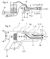
- the paint spraying device 3 has a control 34 in the form of a trigger and controlling the speed of the gas stream 5 in the chamber 9 and / or the selective delivery of the powder paint by the paint introduction means 7
- This trigger 34 may for example control the heating of the electrical resistance 20 and / or the speed of rotation of the motor 22 driving the turbine 21.
- the chamber 9 is connected to a gripping handle allowing the user to move it to orientate its exit and the hot flow comprising painting in the direction desired.
- the introduction means 7 comprise at least one flexible pipe 37 of length greater than 1 meter and connecting these introduction means 7 to the storage means 6. This separation via the flexible pipe 37 allows to leave the reserve of paint which is heavy (storage means with its fluidized bed system) while allowing the user to move the chamber 9 and the introduction means 7 to orient the nozzles relative to the piece to be painted.
- the compressor 24 which generates compressed air can be connected to the chamber 9 of the hot gas flow generating means 5 and in this case replaces the motor 22 and the turbine 4, a controlled valve for selectively controlling the opening and closing of this link.
- the air flow generated by this compressor is heated in the chamber by the electrical resistance located upstream of the zone 8 where the powder paint is introduced.
- This same compressor 24 can also be connected to the storage means 6 as seen on the figure 4 in order firstly to generate the fluidized bed of paint and secondly to create a flow for conveying this powder paint towards the flow of hot air generated in the chamber 9 of the gas flow production means 4 hot.
- This connection can also be selectively controlled by a valve.
- this compressor 24 can also be connected to the cooling circuit 18 as seen in FIG. figure 4 in order to cool the internal nozzle 16 and the paint that passes through it.
- This connection can be selectively controlled by a separate valve whose function is the regulation of the temperature of the inner nozzle 16.
- a temperature sensor can be implanted to evaluate the temperature of the internal nozzle 16 and regulate the opening of the valve according to the rated temperature.
- This regulation with panel 33 is preferably connected to each of said valve and temperature sensors above and possibly flow rate sensors or pressure so as to control the achievement of the aforementioned instructions.
Landscapes
- Nozzles (AREA)
- Electrostatic Spraying Apparatus (AREA)
Claims (6)
- Anordnung (1) zum Lackieren von Objekten (2), umfassend eine Vorrichtung zum Spritzen (3) von Pulverlack (32), die Folgendes umfasst:- Mittel zum Herstellen (4) eines Heißgasstroms (5), die geeignet sind, einen Heißluftstrom herzustellen, der eine Temperatur aufweist, die mindestens zwischen ersten und zweiten Temperaturschwellenwerten liegt;- Mittel zum Lagern (6) des Pulverlacks (32);- Mittel zum Einführen (7) von Pulverlack (32) in den Gasstrom (5), wobei diese Mittel zum Einführen (7) einerseits mit den Mitteln zum Lagern (6) verbunden sind, um daraus Pulverlack (32) zu entnehmen, und andererseits in Richtung einer Zone zur Einführung (8) von Pulverlack (32) münden, die so liegt, dass sie sich gegenüber dem Heißgasstrom (5) befindet, der von den Mitteln zum Herstellen (4) eines Heißgasstroms (5) hergestellt wird,wobei die Mittel zum Herstellen (4) des Heißgasstroms eine Kammer (9) umfassen, die mit einem Lufteinlass (10) und einer Luftauslassdüse (11) und Mitteln zum Erhitzen (12) der Luft versehen ist, die zwischen dem Lufteinlass (10) und der Luftauslassdüse (11) angeordnet sind,
wobei die Mittel zum Einführen von Pulverlack (7) mindestens eine externe Düse (13) umfassen, die außerhalb der Kammer (9) der Mittel zum Herstellen des Heißgasstroms liegt und so ausgerichtet ist, dass die Zone zum Einführen (8) von Pulverlack am Rand der Luftauslassdüse (11) liegt, wobei diese externe Düse (13) auf einem ringförmigen Umlenkelement (14) befestigt ist, um den Lack in Richtung des Heißluftstroms (5) auszurichten, wobei die externe Düse (13) in einem Winkel θ größer als 30°, bezogen auf die mittlere Hauptachse XX der Luftauslassdüse (11), ausgerichtet ist, wobei das Ablenkelement (14) und die externe Düse (13) angeordnet sind, um den Pulverlack im Innern der Düse (13) verwirbeln zu lassen, wobei die Anordnung dadurch gekennzeichnet, dass sich die Zone zum Einführen von Lack (8) in den Heißgasstrom außerhalb der Kammer befindet. - Anordnung nach Anspruch 1, dadurch gekennzeichnet, dass die Mittel zum Herstellen (4) eines Heißgasstroms (5) eine Wärmequelle (20) umfassen, die in der Kammer (9) zwischen dem Lufteinlass (10) der Kammer und der Luftauslassdüse (11) vorgesehen ist.
- Anordnung nach Anspruch 2, dadurch gekennzeichnet, dass die Wärmequelle ein elektrischer Widerstand (20) ist.
- Anordnung nach einem der Ansprüche 1 bis 3, dadurch gekennzeichnet, dass die Mittel zum Herstellen (4) eines Heißgasstroms (5) eine Turbine (21) umfassen, die von einem Elektromotor (22) drehend angetrieben wird.
- Anordnung nach einem der Ansprüche 1 bis 4, dadurch gekennzeichnet, dass die Vorrichtung zum Spritzen (3) von Pulverlack (32) Lufteinlassgitter (10) umfasst, die es ermöglichen, die in die Kammer (9) eintretende Luft zu filtern.
- Anordnung nach mindestens einem der Ansprüche 1 bis 5, dadurch gekennzeichnet, dass sie polymerisierbaren Lack in Pulverform (32) umfasst, der eine Gelatinisierungstemperatur zwischen den ersten und zweiten Temperaturschwellenwerten und eine Temperatur zum Ingangsetzen der Polymerisationsreaktion ebenfalls zwischen diesen ersten und zweiten Temperaturschwellenwerten umfasst.
Applications Claiming Priority (2)
| Application Number | Priority Date | Filing Date | Title |
|---|---|---|---|
| FR1053698A FR2959945B1 (fr) | 2010-05-11 | 2010-05-11 | Ensemble pour la peinture de pieces |
| PCT/FR2011/051049 WO2011141675A1 (fr) | 2010-05-11 | 2011-05-10 | Ensemble pour la peinture de pièces |
Publications (2)
| Publication Number | Publication Date |
|---|---|
| EP2569092A1 EP2569092A1 (de) | 2013-03-20 |
| EP2569092B1 true EP2569092B1 (de) | 2015-12-16 |
Family
ID=42790881
Family Applications (1)
| Application Number | Title | Priority Date | Filing Date |
|---|---|---|---|
| EP11725148.8A Active EP2569092B1 (de) | 2010-05-11 | 2011-05-10 | Anordnung für lackierobjekte |
Country Status (4)
| Country | Link |
|---|---|
| EP (1) | EP2569092B1 (de) |
| ES (1) | ES2564662T3 (de) |
| FR (1) | FR2959945B1 (de) |
| WO (1) | WO2011141675A1 (de) |
Family Cites Families (5)
| Publication number | Priority date | Publication date | Assignee | Title |
|---|---|---|---|---|
| US4065057A (en) * | 1976-07-01 | 1977-12-27 | Durmann George J | Apparatus for spraying heat responsive materials |
| US5503872A (en) * | 1994-03-14 | 1996-04-02 | Mackenzie; Kenneth R. | Flameless plastic coating apparatus and method therefor |
| AU4239997A (en) * | 1996-08-30 | 1998-03-19 | Thomas F. Bernecki | Polymer coating by means of hot gases |
| US20020071906A1 (en) * | 2000-12-13 | 2002-06-13 | Rusch William P. | Method and device for applying a coating |
| DE102004042945A1 (de) * | 2004-09-02 | 2006-03-30 | Eads Deutschland Gmbh | Heißgasspritzpistole, insbesondere zum thermischen Spritzen von Kunststoffen |
-
2010
- 2010-05-11 FR FR1053698A patent/FR2959945B1/fr not_active Expired - Fee Related
-
2011
- 2011-05-10 WO PCT/FR2011/051049 patent/WO2011141675A1/fr not_active Ceased
- 2011-05-10 ES ES11725148.8T patent/ES2564662T3/es active Active
- 2011-05-10 EP EP11725148.8A patent/EP2569092B1/de active Active
Also Published As
| Publication number | Publication date |
|---|---|
| FR2959945B1 (fr) | 2012-08-03 |
| WO2011141675A1 (fr) | 2011-11-17 |
| ES2564662T3 (es) | 2016-03-28 |
| EP2569092A1 (de) | 2013-03-20 |
| FR2959945A1 (fr) | 2011-11-18 |
Similar Documents
| Publication | Publication Date | Title |
|---|---|---|
| EP0521794B1 (de) | Vorrichtung zur Lagerung und Förderung von Eiskugeln, ohne Verschmelzung derselben, von ihrem Herstellungsort bis zu ihrem Verwendungsort wo sie gegen eine Zielfläche geschleudert werden | |
| US20100009093A1 (en) | Thermal spray formation of polymer coatings | |
| ES2665827T3 (es) | Sistema de revestimiento móvil para materiales elastoméricos | |
| CN103930216B (zh) | 用于喷涂弹性体材料的施加器 | |
| US5041713A (en) | Apparatus and method for applying plasma flame sprayed polymers | |
| CN101132864B (zh) | 用于涂覆小型部件的方法和装置 | |
| EP3296022A1 (de) | Vorrichtung zur inbetriebsetzung der drehbewegung einer flüssigkeit in einer düse, anordnung, die eine solche vorrichtung umfasst, und anwendungsvorrichtung | |
| JP2015505908A5 (de) | ||
| CN109554701B (zh) | 一种手机壳体表面的喷涂方法及喷涂装置 | |
| EP2471605A1 (de) | Düse zur Verwendung mit einer Sprühbeschichtungspistole | |
| US7959983B1 (en) | Thermal spray formation of polymer compositions | |
| CN107621202A (zh) | 一种冷焰火瀑布喷射设备 | |
| JP2011011177A (ja) | タンブラーコーティング装置及びタンブラーコーティング方法 | |
| WO2011141675A1 (fr) | Ensemble pour la peinture de pièces | |
| CN101462095A (zh) | 热气喷塑技术 | |
| WO1998008614A9 (en) | Polymer coating by means of hot gases | |
| WO1998008614A1 (en) | Polymer coating by means of hot gases | |
| JP6272443B2 (ja) | 管の塗装装置および塗装方法 | |
| FR3065655B1 (fr) | Pistolet pulverisateur chauffant | |
| EP3632574A1 (de) | Pulverbeschichtungssystem | |
| CN107937904B (zh) | 一种激光冷喷涂制备铝涂层的方法与装置 | |
| CN201324698Y (zh) | 线锯喷覆装置 | |
| BE649283A (fr) | procédés et appareils pour le revètement électrostatique | |
| WO2019002408A1 (fr) | Dispositif de refroidissement de fils galvanisés | |
| FR3086557A1 (fr) | Systeme de poudrage |
Legal Events
| Date | Code | Title | Description |
|---|---|---|---|
| PUAI | Public reference made under article 153(3) epc to a published international application that has entered the european phase |
Free format text: ORIGINAL CODE: 0009012 |
|
| 17P | Request for examination filed |
Effective date: 20121211 |
|
| AK | Designated contracting states |
Kind code of ref document: A1 Designated state(s): AL AT BE BG CH CY CZ DE DK EE ES FI FR GB GR HR HU IE IS IT LI LT LU LV MC MK MT NL NO PL PT RO RS SE SI SK SM TR |
|
| DAX | Request for extension of the european patent (deleted) | ||
| 111L | Licence recorded |
Designated state(s): AL AT BE BG CH CY CZ DE DK EE ES FI FR GB GR HR HU IE IS IT LT LU LV MC MK MT NL NO PL PT RO RS SE SI SK SM TR Free format text: EXCLUSIVE LICENSE Name of requester: JCD FRANCE SAS, FR Effective date: 20131025 |
|
| 17Q | First examination report despatched |
Effective date: 20140813 |
|
| RIC1 | Information provided on ipc code assigned before grant |
Ipc: B05B 7/16 20060101ALI20150507BHEP Ipc: B05B 15/12 20060101ALI20150507BHEP Ipc: B05B 7/14 20060101AFI20150507BHEP |
|
| GRAP | Despatch of communication of intention to grant a patent |
Free format text: ORIGINAL CODE: EPIDOSNIGR1 |
|
| INTG | Intention to grant announced |
Effective date: 20150625 |
|
| GRAS | Grant fee paid |
Free format text: ORIGINAL CODE: EPIDOSNIGR3 |
|
| GRAP | Despatch of communication of intention to grant a patent |
Free format text: ORIGINAL CODE: EPIDOSNIGR1 |
|
| INTG | Intention to grant announced |
Effective date: 20151015 |
|
| GRAA | (expected) grant |
Free format text: ORIGINAL CODE: 0009210 |
|
| 111L | Licence recorded |
Designated state(s): AL AT BE BG CH CY CZ DE DK EE ES FI FR GB GR HR HU IE IS IT LT LU LV MC MK MT NL NO PL PT RO RS SE SI SK SM TR Free format text: EXCLUSIVE LICENSE Name of requester: JCD FRANCE SAS, FR Effective date: 20131025 |
|
| AK | Designated contracting states |
Kind code of ref document: B1 Designated state(s): AL AT BE BG CH CY CZ DE DK EE ES FI FR GB GR HR HU IE IS IT LI LT LU LV MC MK MT NL NO PL PT RO RS SE SI SK SM TR |
|
| REG | Reference to a national code |
Ref country code: GB Ref legal event code: FG4D Free format text: NOT ENGLISH |
|
| REG | Reference to a national code |
Ref country code: CH Ref legal event code: EP Ref country code: CH Ref legal event code: PK Free format text: COMPLETEMENT D'ENREGISTREMENT DE LICENCE: LICENCE EXCLUSIVE |
|
| REG | Reference to a national code |
Ref country code: IE Ref legal event code: FG4D Free format text: LANGUAGE OF EP DOCUMENT: FRENCH |
|
| REG | Reference to a national code |
Ref country code: AT Ref legal event code: REF Ref document number: 765267 Country of ref document: AT Kind code of ref document: T Effective date: 20160115 |
|
| REG | Reference to a national code |
Ref country code: DE Ref legal event code: R096 Ref document number: 602011022036 Country of ref document: DE |
|
| REG | Reference to a national code |
Ref country code: CH Ref legal event code: NV Representative=s name: NOVAGRAAF INTERNATIONAL SA, CH |
|
| REG | Reference to a national code |
Ref country code: FR Ref legal event code: PLFP Year of fee payment: 6 |
|
| REG | Reference to a national code |
Ref country code: ES Ref legal event code: FG2A Ref document number: 2564662 Country of ref document: ES Kind code of ref document: T3 Effective date: 20160328 |
|
| REG | Reference to a national code |
Ref country code: NL Ref legal event code: MP Effective date: 20151216 |
|
| REG | Reference to a national code |
Ref country code: LT Ref legal event code: MG4D |
|
| PG25 | Lapsed in a contracting state [announced via postgrant information from national office to epo] |
Ref country code: NO Free format text: LAPSE BECAUSE OF FAILURE TO SUBMIT A TRANSLATION OF THE DESCRIPTION OR TO PAY THE FEE WITHIN THE PRESCRIBED TIME-LIMIT Effective date: 20160316 Ref country code: HR Free format text: LAPSE BECAUSE OF FAILURE TO SUBMIT A TRANSLATION OF THE DESCRIPTION OR TO PAY THE FEE WITHIN THE PRESCRIBED TIME-LIMIT Effective date: 20151216 Ref country code: LT Free format text: LAPSE BECAUSE OF FAILURE TO SUBMIT A TRANSLATION OF THE DESCRIPTION OR TO PAY THE FEE WITHIN THE PRESCRIBED TIME-LIMIT Effective date: 20151216 |
|
| REG | Reference to a national code |
Ref country code: AT Ref legal event code: MK05 Ref document number: 765267 Country of ref document: AT Kind code of ref document: T Effective date: 20151216 |
|
| PG25 | Lapsed in a contracting state [announced via postgrant information from national office to epo] |
Ref country code: GR Free format text: LAPSE BECAUSE OF FAILURE TO SUBMIT A TRANSLATION OF THE DESCRIPTION OR TO PAY THE FEE WITHIN THE PRESCRIBED TIME-LIMIT Effective date: 20160317 Ref country code: LV Free format text: LAPSE BECAUSE OF FAILURE TO SUBMIT A TRANSLATION OF THE DESCRIPTION OR TO PAY THE FEE WITHIN THE PRESCRIBED TIME-LIMIT Effective date: 20151216 Ref country code: RS Free format text: LAPSE BECAUSE OF FAILURE TO SUBMIT A TRANSLATION OF THE DESCRIPTION OR TO PAY THE FEE WITHIN THE PRESCRIBED TIME-LIMIT Effective date: 20151216 Ref country code: NL Free format text: LAPSE BECAUSE OF FAILURE TO SUBMIT A TRANSLATION OF THE DESCRIPTION OR TO PAY THE FEE WITHIN THE PRESCRIBED TIME-LIMIT Effective date: 20151216 Ref country code: FI Free format text: LAPSE BECAUSE OF FAILURE TO SUBMIT A TRANSLATION OF THE DESCRIPTION OR TO PAY THE FEE WITHIN THE PRESCRIBED TIME-LIMIT Effective date: 20151216 Ref country code: SE Free format text: LAPSE BECAUSE OF FAILURE TO SUBMIT A TRANSLATION OF THE DESCRIPTION OR TO PAY THE FEE WITHIN THE PRESCRIBED TIME-LIMIT Effective date: 20151216 |
|
| PG25 | Lapsed in a contracting state [announced via postgrant information from national office to epo] |
Ref country code: CZ Free format text: LAPSE BECAUSE OF FAILURE TO SUBMIT A TRANSLATION OF THE DESCRIPTION OR TO PAY THE FEE WITHIN THE PRESCRIBED TIME-LIMIT Effective date: 20151216 |
|
| PG25 | Lapsed in a contracting state [announced via postgrant information from national office to epo] |
Ref country code: SM Free format text: LAPSE BECAUSE OF FAILURE TO SUBMIT A TRANSLATION OF THE DESCRIPTION OR TO PAY THE FEE WITHIN THE PRESCRIBED TIME-LIMIT Effective date: 20151216 Ref country code: SK Free format text: LAPSE BECAUSE OF FAILURE TO SUBMIT A TRANSLATION OF THE DESCRIPTION OR TO PAY THE FEE WITHIN THE PRESCRIBED TIME-LIMIT Effective date: 20151216 Ref country code: RO Free format text: LAPSE BECAUSE OF FAILURE TO SUBMIT A TRANSLATION OF THE DESCRIPTION OR TO PAY THE FEE WITHIN THE PRESCRIBED TIME-LIMIT Effective date: 20151216 Ref country code: AT Free format text: LAPSE BECAUSE OF FAILURE TO SUBMIT A TRANSLATION OF THE DESCRIPTION OR TO PAY THE FEE WITHIN THE PRESCRIBED TIME-LIMIT Effective date: 20151216 Ref country code: IS Free format text: LAPSE BECAUSE OF FAILURE TO SUBMIT A TRANSLATION OF THE DESCRIPTION OR TO PAY THE FEE WITHIN THE PRESCRIBED TIME-LIMIT Effective date: 20160416 Ref country code: PT Free format text: LAPSE BECAUSE OF FAILURE TO SUBMIT A TRANSLATION OF THE DESCRIPTION OR TO PAY THE FEE WITHIN THE PRESCRIBED TIME-LIMIT Effective date: 20160418 Ref country code: EE Free format text: LAPSE BECAUSE OF FAILURE TO SUBMIT A TRANSLATION OF THE DESCRIPTION OR TO PAY THE FEE WITHIN THE PRESCRIBED TIME-LIMIT Effective date: 20151216 |
|
| REG | Reference to a national code |
Ref country code: DE Ref legal event code: R097 Ref document number: 602011022036 Country of ref document: DE |
|
| PLBE | No opposition filed within time limit |
Free format text: ORIGINAL CODE: 0009261 |
|
| STAA | Information on the status of an ep patent application or granted ep patent |
Free format text: STATUS: NO OPPOSITION FILED WITHIN TIME LIMIT |
|
| PG25 | Lapsed in a contracting state [announced via postgrant information from national office to epo] |
Ref country code: DK Free format text: LAPSE BECAUSE OF FAILURE TO SUBMIT A TRANSLATION OF THE DESCRIPTION OR TO PAY THE FEE WITHIN THE PRESCRIBED TIME-LIMIT Effective date: 20151216 Ref country code: PL Free format text: LAPSE BECAUSE OF FAILURE TO SUBMIT A TRANSLATION OF THE DESCRIPTION OR TO PAY THE FEE WITHIN THE PRESCRIBED TIME-LIMIT Effective date: 20151216 |
|
| 26N | No opposition filed |
Effective date: 20160919 |
|
| REG | Reference to a national code |
Ref country code: IE Ref legal event code: MM4A |
|
| PG25 | Lapsed in a contracting state [announced via postgrant information from national office to epo] |
Ref country code: SI Free format text: LAPSE BECAUSE OF FAILURE TO SUBMIT A TRANSLATION OF THE DESCRIPTION OR TO PAY THE FEE WITHIN THE PRESCRIBED TIME-LIMIT Effective date: 20151216 |
|
| REG | Reference to a national code |
Ref country code: FR Ref legal event code: PLFP Year of fee payment: 7 |
|
| PG25 | Lapsed in a contracting state [announced via postgrant information from national office to epo] |
Ref country code: IE Free format text: LAPSE BECAUSE OF NON-PAYMENT OF DUE FEES Effective date: 20160510 |
|
| REG | Reference to a national code |
Ref country code: FR Ref legal event code: PLFP Year of fee payment: 8 |
|
| PG25 | Lapsed in a contracting state [announced via postgrant information from national office to epo] |
Ref country code: CY Free format text: LAPSE BECAUSE OF FAILURE TO SUBMIT A TRANSLATION OF THE DESCRIPTION OR TO PAY THE FEE WITHIN THE PRESCRIBED TIME-LIMIT Effective date: 20151216 Ref country code: HU Free format text: LAPSE BECAUSE OF FAILURE TO SUBMIT A TRANSLATION OF THE DESCRIPTION OR TO PAY THE FEE WITHIN THE PRESCRIBED TIME-LIMIT; INVALID AB INITIO Effective date: 20110510 |
|
| PG25 | Lapsed in a contracting state [announced via postgrant information from national office to epo] |
Ref country code: TR Free format text: LAPSE BECAUSE OF FAILURE TO SUBMIT A TRANSLATION OF THE DESCRIPTION OR TO PAY THE FEE WITHIN THE PRESCRIBED TIME-LIMIT Effective date: 20151216 Ref country code: MT Free format text: LAPSE BECAUSE OF FAILURE TO SUBMIT A TRANSLATION OF THE DESCRIPTION OR TO PAY THE FEE WITHIN THE PRESCRIBED TIME-LIMIT Effective date: 20151216 Ref country code: MK Free format text: LAPSE BECAUSE OF FAILURE TO SUBMIT A TRANSLATION OF THE DESCRIPTION OR TO PAY THE FEE WITHIN THE PRESCRIBED TIME-LIMIT Effective date: 20151216 |
|
| PG25 | Lapsed in a contracting state [announced via postgrant information from national office to epo] |
Ref country code: BG Free format text: LAPSE BECAUSE OF FAILURE TO SUBMIT A TRANSLATION OF THE DESCRIPTION OR TO PAY THE FEE WITHIN THE PRESCRIBED TIME-LIMIT Effective date: 20151216 |
|
| PG25 | Lapsed in a contracting state [announced via postgrant information from national office to epo] |
Ref country code: AL Free format text: LAPSE BECAUSE OF FAILURE TO SUBMIT A TRANSLATION OF THE DESCRIPTION OR TO PAY THE FEE WITHIN THE PRESCRIBED TIME-LIMIT Effective date: 20151216 |
|
| PGFP | Annual fee paid to national office [announced via postgrant information from national office to epo] |
Ref country code: LU Payment date: 20200518 Year of fee payment: 10 Ref country code: CH Payment date: 20200528 Year of fee payment: 10 Ref country code: MC Payment date: 20200519 Year of fee payment: 10 Ref country code: ES Payment date: 20200618 Year of fee payment: 10 Ref country code: DE Payment date: 20200528 Year of fee payment: 10 |
|
| PGFP | Annual fee paid to national office [announced via postgrant information from national office to epo] |
Ref country code: BE Payment date: 20200529 Year of fee payment: 10 Ref country code: GB Payment date: 20200528 Year of fee payment: 10 Ref country code: IT Payment date: 20200528 Year of fee payment: 10 |
|
| REG | Reference to a national code |
Ref country code: DE Ref legal event code: R119 Ref document number: 602011022036 Country of ref document: DE |
|
| REG | Reference to a national code |
Ref country code: CH Ref legal event code: PL |
|
| GBPC | Gb: european patent ceased through non-payment of renewal fee |
Effective date: 20210510 |
|
| PG25 | Lapsed in a contracting state [announced via postgrant information from national office to epo] |
Ref country code: CH Free format text: LAPSE BECAUSE OF NON-PAYMENT OF DUE FEES Effective date: 20210531 Ref country code: MC Free format text: LAPSE BECAUSE OF NON-PAYMENT OF DUE FEES Effective date: 20210531 Ref country code: LI Free format text: LAPSE BECAUSE OF NON-PAYMENT OF DUE FEES Effective date: 20210531 Ref country code: LU Free format text: LAPSE BECAUSE OF NON-PAYMENT OF DUE FEES Effective date: 20210510 |
|
| REG | Reference to a national code |
Ref country code: BE Ref legal event code: MM Effective date: 20210531 |
|
| PG25 | Lapsed in a contracting state [announced via postgrant information from national office to epo] |
Ref country code: GB Free format text: LAPSE BECAUSE OF NON-PAYMENT OF DUE FEES Effective date: 20210510 Ref country code: DE Free format text: LAPSE BECAUSE OF NON-PAYMENT OF DUE FEES Effective date: 20211201 |
|
| PG25 | Lapsed in a contracting state [announced via postgrant information from national office to epo] |
Ref country code: BE Free format text: LAPSE BECAUSE OF NON-PAYMENT OF DUE FEES Effective date: 20210531 |
|
| REG | Reference to a national code |
Ref country code: ES Ref legal event code: FD2A Effective date: 20220801 |
|
| PG25 | Lapsed in a contracting state [announced via postgrant information from national office to epo] |
Ref country code: ES Free format text: LAPSE BECAUSE OF NON-PAYMENT OF DUE FEES Effective date: 20210511 |
|
| PG25 | Lapsed in a contracting state [announced via postgrant information from national office to epo] |
Ref country code: IT Free format text: LAPSE BECAUSE OF NON-PAYMENT OF DUE FEES Effective date: 20200510 |
|
| P01 | Opt-out of the competence of the unified patent court (upc) registered |
Effective date: 20230601 |
|
| PGFP | Annual fee paid to national office [announced via postgrant information from national office to epo] |
Ref country code: FR Payment date: 20250526 Year of fee payment: 15 |
|
| PG25 | Lapsed in a contracting state [announced via postgrant information from national office to epo] |
Ref country code: IT Free format text: LAPSE BECAUSE OF NON-PAYMENT OF DUE FEES Effective date: 20210510 |